WO2019244402A1 - 二次電池モジュール - Google Patents
二次電池モジュール Download PDFInfo
- Publication number
- WO2019244402A1 WO2019244402A1 PCT/JP2019/007086 JP2019007086W WO2019244402A1 WO 2019244402 A1 WO2019244402 A1 WO 2019244402A1 JP 2019007086 W JP2019007086 W JP 2019007086W WO 2019244402 A1 WO2019244402 A1 WO 2019244402A1
- Authority
- WO
- WIPO (PCT)
- Prior art keywords
- bus bar
- battery
- secondary battery
- module
- block
- Prior art date
- Legal status (The legal status is an assumption and is not a legal conclusion. Google has not performed a legal analysis and makes no representation as to the accuracy of the status listed.)
- Ceased
Links
Images


Classifications
-
- H—ELECTRICITY
- H01—ELECTRIC ELEMENTS
- H01M—PROCESSES OR MEANS, e.g. BATTERIES, FOR THE DIRECT CONVERSION OF CHEMICAL ENERGY INTO ELECTRICAL ENERGY
- H01M50/00—Constructional details or processes of manufacture of the non-active parts of electrochemical cells other than fuel cells, e.g. hybrid cells
- H01M50/50—Current conducting connections for cells or batteries
- H01M50/502—Interconnectors for connecting terminals of adjacent batteries; Interconnectors for connecting cells outside a battery casing
-
- H—ELECTRICITY
- H01—ELECTRIC ELEMENTS
- H01M—PROCESSES OR MEANS, e.g. BATTERIES, FOR THE DIRECT CONVERSION OF CHEMICAL ENERGY INTO ELECTRICAL ENERGY
- H01M50/00—Constructional details or processes of manufacture of the non-active parts of electrochemical cells other than fuel cells, e.g. hybrid cells
- H01M50/20—Mountings; Secondary casings or frames; Racks, modules or packs; Suspension devices; Shock absorbers; Transport or carrying devices; Holders
- H01M50/204—Racks, modules or packs for multiple batteries or multiple cells
-
- H—ELECTRICITY
- H01—ELECTRIC ELEMENTS
- H01M—PROCESSES OR MEANS, e.g. BATTERIES, FOR THE DIRECT CONVERSION OF CHEMICAL ENERGY INTO ELECTRICAL ENERGY
- H01M50/00—Constructional details or processes of manufacture of the non-active parts of electrochemical cells other than fuel cells, e.g. hybrid cells
- H01M50/20—Mountings; Secondary casings or frames; Racks, modules or packs; Suspension devices; Shock absorbers; Transport or carrying devices; Holders
- H01M50/204—Racks, modules or packs for multiple batteries or multiple cells
- H01M50/207—Racks, modules or packs for multiple batteries or multiple cells characterised by their shape
- H01M50/209—Racks, modules or packs for multiple batteries or multiple cells characterised by their shape adapted for prismatic or rectangular cells
-
- H—ELECTRICITY
- H01—ELECTRIC ELEMENTS
- H01M—PROCESSES OR MEANS, e.g. BATTERIES, FOR THE DIRECT CONVERSION OF CHEMICAL ENERGY INTO ELECTRICAL ENERGY
- H01M50/00—Constructional details or processes of manufacture of the non-active parts of electrochemical cells other than fuel cells, e.g. hybrid cells
- H01M50/20—Mountings; Secondary casings or frames; Racks, modules or packs; Suspension devices; Shock absorbers; Transport or carrying devices; Holders
- H01M50/233—Mountings; Secondary casings or frames; Racks, modules or packs; Suspension devices; Shock absorbers; Transport or carrying devices; Holders characterised by physical properties of casings or racks, e.g. dimensions
- H01M50/242—Mountings; Secondary casings or frames; Racks, modules or packs; Suspension devices; Shock absorbers; Transport or carrying devices; Holders characterised by physical properties of casings or racks, e.g. dimensions adapted for protecting batteries against vibrations, collision impact or swelling
-
- H—ELECTRICITY
- H01—ELECTRIC ELEMENTS
- H01M—PROCESSES OR MEANS, e.g. BATTERIES, FOR THE DIRECT CONVERSION OF CHEMICAL ENERGY INTO ELECTRICAL ENERGY
- H01M50/00—Constructional details or processes of manufacture of the non-active parts of electrochemical cells other than fuel cells, e.g. hybrid cells
- H01M50/20—Mountings; Secondary casings or frames; Racks, modules or packs; Suspension devices; Shock absorbers; Transport or carrying devices; Holders
- H01M50/244—Secondary casings; Racks; Suspension devices; Carrying devices; Holders characterised by their mounting method
-
- H—ELECTRICITY
- H01—ELECTRIC ELEMENTS
- H01M—PROCESSES OR MEANS, e.g. BATTERIES, FOR THE DIRECT CONVERSION OF CHEMICAL ENERGY INTO ELECTRICAL ENERGY
- H01M50/00—Constructional details or processes of manufacture of the non-active parts of electrochemical cells other than fuel cells, e.g. hybrid cells
- H01M50/20—Mountings; Secondary casings or frames; Racks, modules or packs; Suspension devices; Shock absorbers; Transport or carrying devices; Holders
- H01M50/258—Modular batteries; Casings provided with means for assembling
-
- H—ELECTRICITY
- H01—ELECTRIC ELEMENTS
- H01M—PROCESSES OR MEANS, e.g. BATTERIES, FOR THE DIRECT CONVERSION OF CHEMICAL ENERGY INTO ELECTRICAL ENERGY
- H01M50/00—Constructional details or processes of manufacture of the non-active parts of electrochemical cells other than fuel cells, e.g. hybrid cells
- H01M50/20—Mountings; Secondary casings or frames; Racks, modules or packs; Suspension devices; Shock absorbers; Transport or carrying devices; Holders
- H01M50/262—Mountings; Secondary casings or frames; Racks, modules or packs; Suspension devices; Shock absorbers; Transport or carrying devices; Holders with fastening means, e.g. locks
-
- H—ELECTRICITY
- H01—ELECTRIC ELEMENTS
- H01M—PROCESSES OR MEANS, e.g. BATTERIES, FOR THE DIRECT CONVERSION OF CHEMICAL ENERGY INTO ELECTRICAL ENERGY
- H01M50/00—Constructional details or processes of manufacture of the non-active parts of electrochemical cells other than fuel cells, e.g. hybrid cells
- H01M50/20—Mountings; Secondary casings or frames; Racks, modules or packs; Suspension devices; Shock absorbers; Transport or carrying devices; Holders
- H01M50/262—Mountings; Secondary casings or frames; Racks, modules or packs; Suspension devices; Shock absorbers; Transport or carrying devices; Holders with fastening means, e.g. locks
- H01M50/264—Mountings; Secondary casings or frames; Racks, modules or packs; Suspension devices; Shock absorbers; Transport or carrying devices; Holders with fastening means, e.g. locks for cells or batteries, e.g. straps, tie rods or peripheral frames
-
- H—ELECTRICITY
- H01—ELECTRIC ELEMENTS
- H01M—PROCESSES OR MEANS, e.g. BATTERIES, FOR THE DIRECT CONVERSION OF CHEMICAL ENERGY INTO ELECTRICAL ENERGY
- H01M50/00—Constructional details or processes of manufacture of the non-active parts of electrochemical cells other than fuel cells, e.g. hybrid cells
- H01M50/20—Mountings; Secondary casings or frames; Racks, modules or packs; Suspension devices; Shock absorbers; Transport or carrying devices; Holders
- H01M50/289—Mountings; Secondary casings or frames; Racks, modules or packs; Suspension devices; Shock absorbers; Transport or carrying devices; Holders characterised by spacing elements or positioning means within frames, racks or packs
- H01M50/291—Mountings; Secondary casings or frames; Racks, modules or packs; Suspension devices; Shock absorbers; Transport or carrying devices; Holders characterised by spacing elements or positioning means within frames, racks or packs characterised by their shape
-
- H—ELECTRICITY
- H01—ELECTRIC ELEMENTS
- H01M—PROCESSES OR MEANS, e.g. BATTERIES, FOR THE DIRECT CONVERSION OF CHEMICAL ENERGY INTO ELECTRICAL ENERGY
- H01M50/00—Constructional details or processes of manufacture of the non-active parts of electrochemical cells other than fuel cells, e.g. hybrid cells
- H01M50/20—Mountings; Secondary casings or frames; Racks, modules or packs; Suspension devices; Shock absorbers; Transport or carrying devices; Holders
- H01M50/296—Mountings; Secondary casings or frames; Racks, modules or packs; Suspension devices; Shock absorbers; Transport or carrying devices; Holders characterised by terminals of battery packs
-
- H—ELECTRICITY
- H01—ELECTRIC ELEMENTS
- H01M—PROCESSES OR MEANS, e.g. BATTERIES, FOR THE DIRECT CONVERSION OF CHEMICAL ENERGY INTO ELECTRICAL ENERGY
- H01M50/00—Constructional details or processes of manufacture of the non-active parts of electrochemical cells other than fuel cells, e.g. hybrid cells
- H01M50/20—Mountings; Secondary casings or frames; Racks, modules or packs; Suspension devices; Shock absorbers; Transport or carrying devices; Holders
- H01M50/298—Mountings; Secondary casings or frames; Racks, modules or packs; Suspension devices; Shock absorbers; Transport or carrying devices; Holders characterised by the wiring of battery packs
-
- H—ELECTRICITY
- H01—ELECTRIC ELEMENTS
- H01M—PROCESSES OR MEANS, e.g. BATTERIES, FOR THE DIRECT CONVERSION OF CHEMICAL ENERGY INTO ELECTRICAL ENERGY
- H01M50/00—Constructional details or processes of manufacture of the non-active parts of electrochemical cells other than fuel cells, e.g. hybrid cells
- H01M50/50—Current conducting connections for cells or batteries
-
- H—ELECTRICITY
- H01—ELECTRIC ELEMENTS
- H01M—PROCESSES OR MEANS, e.g. BATTERIES, FOR THE DIRECT CONVERSION OF CHEMICAL ENERGY INTO ELECTRICAL ENERGY
- H01M50/00—Constructional details or processes of manufacture of the non-active parts of electrochemical cells other than fuel cells, e.g. hybrid cells
- H01M50/50—Current conducting connections for cells or batteries
- H01M50/502—Interconnectors for connecting terminals of adjacent batteries; Interconnectors for connecting cells outside a battery casing
- H01M50/503—Interconnectors for connecting terminals of adjacent batteries; Interconnectors for connecting cells outside a battery casing characterised by the shape of the interconnectors
-
- H—ELECTRICITY
- H01—ELECTRIC ELEMENTS
- H01M—PROCESSES OR MEANS, e.g. BATTERIES, FOR THE DIRECT CONVERSION OF CHEMICAL ENERGY INTO ELECTRICAL ENERGY
- H01M50/00—Constructional details or processes of manufacture of the non-active parts of electrochemical cells other than fuel cells, e.g. hybrid cells
- H01M50/50—Current conducting connections for cells or batteries
- H01M50/502—Interconnectors for connecting terminals of adjacent batteries; Interconnectors for connecting cells outside a battery casing
- H01M50/505—Interconnectors for connecting terminals of adjacent batteries; Interconnectors for connecting cells outside a battery casing comprising a single busbar
-
- H—ELECTRICITY
- H01—ELECTRIC ELEMENTS
- H01M—PROCESSES OR MEANS, e.g. BATTERIES, FOR THE DIRECT CONVERSION OF CHEMICAL ENERGY INTO ELECTRICAL ENERGY
- H01M50/00—Constructional details or processes of manufacture of the non-active parts of electrochemical cells other than fuel cells, e.g. hybrid cells
- H01M50/50—Current conducting connections for cells or batteries
- H01M50/502—Interconnectors for connecting terminals of adjacent batteries; Interconnectors for connecting cells outside a battery casing
- H01M50/514—Methods for interconnecting adjacent batteries or cells
- H01M50/516—Methods for interconnecting adjacent batteries or cells by welding, soldering or brazing
-
- H—ELECTRICITY
- H01—ELECTRIC ELEMENTS
- H01M—PROCESSES OR MEANS, e.g. BATTERIES, FOR THE DIRECT CONVERSION OF CHEMICAL ENERGY INTO ELECTRICAL ENERGY
- H01M50/00—Constructional details or processes of manufacture of the non-active parts of electrochemical cells other than fuel cells, e.g. hybrid cells
- H01M50/50—Current conducting connections for cells or batteries
- H01M50/502—Interconnectors for connecting terminals of adjacent batteries; Interconnectors for connecting cells outside a battery casing
- H01M50/521—Interconnectors for connecting terminals of adjacent batteries; Interconnectors for connecting cells outside a battery casing characterised by the material
- H01M50/522—Inorganic material
-
- H—ELECTRICITY
- H01—ELECTRIC ELEMENTS
- H01M—PROCESSES OR MEANS, e.g. BATTERIES, FOR THE DIRECT CONVERSION OF CHEMICAL ENERGY INTO ELECTRICAL ENERGY
- H01M50/00—Constructional details or processes of manufacture of the non-active parts of electrochemical cells other than fuel cells, e.g. hybrid cells
- H01M50/50—Current conducting connections for cells or batteries
- H01M50/528—Fixed electrical connections, i.e. not intended for disconnection
-
- H—ELECTRICITY
- H01—ELECTRIC ELEMENTS
- H01M—PROCESSES OR MEANS, e.g. BATTERIES, FOR THE DIRECT CONVERSION OF CHEMICAL ENERGY INTO ELECTRICAL ENERGY
- H01M50/00—Constructional details or processes of manufacture of the non-active parts of electrochemical cells other than fuel cells, e.g. hybrid cells
- H01M50/50—Current conducting connections for cells or batteries
- H01M50/543—Terminals
-
- H—ELECTRICITY
- H01—ELECTRIC ELEMENTS
- H01M—PROCESSES OR MEANS, e.g. BATTERIES, FOR THE DIRECT CONVERSION OF CHEMICAL ENERGY INTO ELECTRICAL ENERGY
- H01M50/00—Constructional details or processes of manufacture of the non-active parts of electrochemical cells other than fuel cells, e.g. hybrid cells
- H01M50/50—Current conducting connections for cells or batteries
- H01M50/572—Means for preventing undesired use or discharge
- H01M50/574—Devices or arrangements for the interruption of current
- H01M50/583—Devices or arrangements for the interruption of current in response to current, e.g. fuses
-
- H—ELECTRICITY
- H01—ELECTRIC ELEMENTS
- H01M—PROCESSES OR MEANS, e.g. BATTERIES, FOR THE DIRECT CONVERSION OF CHEMICAL ENERGY INTO ELECTRICAL ENERGY
- H01M2200/00—Safety devices for primary or secondary batteries
- H01M2200/10—Temperature sensitive devices
- H01M2200/103—Fuse
-
- Y—GENERAL TAGGING OF NEW TECHNOLOGICAL DEVELOPMENTS; GENERAL TAGGING OF CROSS-SECTIONAL TECHNOLOGIES SPANNING OVER SEVERAL SECTIONS OF THE IPC; TECHNICAL SUBJECTS COVERED BY FORMER USPC CROSS-REFERENCE ART COLLECTIONS [XRACs] AND DIGESTS
- Y02—TECHNOLOGIES OR APPLICATIONS FOR MITIGATION OR ADAPTATION AGAINST CLIMATE CHANGE
- Y02E—REDUCTION OF GREENHOUSE GAS [GHG] EMISSIONS, RELATED TO ENERGY GENERATION, TRANSMISSION OR DISTRIBUTION
- Y02E60/00—Enabling technologies; Technologies with a potential or indirect contribution to GHG emissions mitigation
- Y02E60/10—Energy storage using batteries
Definitions
- the present invention relates to a secondary battery module.
- Priority is claimed on Japanese Patent Application No. 2018-118425 filed on June 22, 2018, the contents of which are incorporated herein by reference.
- a secondary battery module formed by stacking a plurality of battery cells is known.
- the battery cells are electrically connected to each other by a bus bar.
- a so-called bus bar with a fuse function in which a fuse portion is provided in one of the plurality of bus bars, is employed.
- a bus bar with a fuse function having a small cross-sectional area portion ie, a fuse portion
- a fuse portion having a smaller cross-sectional area than other portions
- the present invention has been made to solve such a technical problem, and an object of the present invention is to provide a secondary battery module capable of reducing stress applied to a fuse portion and suppressing breakage of the fuse portion.
- a secondary battery module is a secondary battery module having a plurality of battery blocks in which a plurality of battery cells are stacked, and sandwiches a plurality of the battery blocks and faces a pair of end plates facing each other.
- a sandwiching body having a pair of side plates and a section plate disposed between the battery blocks to partition these battery blocks, and electrically connecting the adjacent battery blocks to each other and straddling the section plate.
- an inter-block bus bar provided with a fuse section.
- the inter-block bus bar is provided with a fuse portion.
- the secondary battery module according to the present invention is a secondary battery module having at least one battery block in which a plurality of battery cells are stacked, sandwiching the battery block, a pair of end plates facing each other, A holding body having a pair of opposed side plates, one end of which is electrically connected to the battery block, and the other end of which is extended to the end plate or the side plate and a module external connection terminal; And a plurality of module end bus bars electrically connected to each other, wherein at least one of the plurality of module end bus bars is provided with a fuse portion.
- the stress applied to the fuse portion can be reduced, and the breakage of the fuse portion can be suppressed.
- FIG. 2 is a perspective view showing the secondary battery module according to the first embodiment.
- FIG. 2 is a plan view showing the secondary battery module according to the first embodiment. It is a perspective view which shows a battery cell. It is a perspective view which shows the bus bar between blocks. It is a perspective view showing a module end part bus bar. It is a schematic perspective view which shows a mode that the battery block clamped by the clamping body is accommodated in a housing
- the “stacking direction of battery cells” may be abbreviated as the “stacking direction” in order to avoid complication.
- FIG. 1 is a perspective view showing the secondary battery module according to the first embodiment
- FIG. 2 is a plan view showing the secondary battery module according to the first embodiment.
- the secondary battery module 1 according to the present embodiment mainly includes two battery blocks 10 in which a plurality of battery cells 11 are stacked in a certain direction, and two battery blocks in which battery cells 11 are arranged in series in the stacking direction. And a holding member 20 for holding the holding member 10.
- the battery block 10 is configured by stacking a plurality of (here, 17) flat rectangular battery cells 11 in a stacking direction with a cell holder (not shown) made of an insulating resin material interposed therebetween. ing.
- FIG. 3 is a perspective view showing a battery cell.
- the battery cell 11 has a battery can 12 and a battery cover 13.
- the battery can 12 has a so-called bottomed rectangular cylindrical shape, and has a rectangular can bottom portion 12a and a pair of wide ends which rise from four rounds of the can bottom portion 12a and have a relatively large area and are opposed to each other. It has a side surface portion 12b and a pair of narrow side surface portions 12c formed to have a relatively small area and opposed to each other.
- a flat electrode group and an electrolytic solution are accommodated inside the battery can 12, for example.
- the battery lid 13 has a substantially rectangular shape and is joined to the battery can 12 so as to close the opening of the battery can 12. As a joining method, laser welding or the like can be given.
- the battery cover 13 has a positive electrode terminal 14 and a negative electrode terminal 15 projecting therefrom. Each end of the positive electrode terminal 14 and the negative electrode terminal 15 is formed in a planar shape so as to be easily joined to the inter-cell bus bar 31, the inter-block bus bar 32, or the module end bus bar 33 (described later) by laser welding. I have.
- the battery cover 13 is provided with a gas discharge valve 16.
- the gas discharge valve 16 opens and gas is discharged from the inside. Thereby, the pressure inside the battery cell 11 is reduced, so that the safety of the battery cell 11 can be ensured.
- the battery lid 13 is provided with a liquid injection plug 17 for closing the liquid injection port of the electrolytic solution.
- the filling plug 17 is joined to the battery lid 13 by laser welding, for example, after filling the inside of the battery cell 11 with an electrolytic solution through a filling port.
- the plurality of battery cells 11 having such a structure are alternately inverted by 180 ° such that the positive electrode terminal 14 of one of the adjacent battery cells 11 and the negative electrode terminal 15 of the other battery cell 11 are adjacent to each other in the stacking direction. They are stacked in a state.
- the positive terminal 14 of one adjacent battery cell 11 and the negative terminal 15 of the other battery cell 11 are electrically connected by an inter-cell bus bar 31.
- the inter-cell bus bar 31 is formed in, for example, an aluminum material in a flat plate shape, and is mounted on these terminals by laser welding while being mounted on these terminals so as to cover the positive electrode terminal 14 and the negative electrode terminal 15. ing.
- the holding body 20 is formed, for example, in a box shape that opens upward, and has a rectangular bottom plate portion 24, a pair of end plates 21 and a pair of side plates 22 rising from four rounds of the bottom plate portion 24, and a bottom plate portion 24. , A section plate 23 disposed inside a space formed by the end plate 21 and the side plate 22.
- the pair of end plates 21 are arranged on both sides in the stacking direction of the battery cells 11 so as to face each other.
- the end plate 21 is formed of, for example, a metal material, extends in a direction perpendicular to the stacking direction of the battery cells 11, and has a predetermined width in the stacking direction.
- the end plate 21 is provided with two screw holes 21a separated at a predetermined interval.
- the end plate 21 is fastened to the housing 40 together with the bottom plate 24 by screws 25 (see FIG. 6) inserted into these screw holes 21a.
- the screw 25 is a fastening member for fastening the end plate 21 to the housing 40.
- the pair of side plates 22 are formed thinner than the end plates 21 and extend along the stacking direction.
- the side plate 22 is formed integrally with the bottom plate 24 by, for example, bending a single metal plate into a U-shape.
- the side plate 22 may be formed separately from the bottom plate 24, for example, and may be fixed to the bottom plate 24 by welding, screwing, or the like.
- the section plate 23 is disposed between the battery blocks 10 so as to partition the battery blocks 10 from each other, and is provided in parallel with the end plate 21.
- the section plate 23 has a rectangular shape, and a relatively narrow portion extends along the direction in which the battery cells 11 are stacked. Therefore, as shown in FIGS. 1 and 2, the upper surface of the section plate 23 is a narrow surface 23a along the laminating direction.
- the section plate 23 is provided with two screw holes 23b separated at a predetermined interval.
- the section plate 23 is fastened to the housing 40 together with the bottom plate 24 by screws 25 (see FIG. 6) inserted into these screw holes 23b.
- the screw 25 is a fastening member for fastening the section plate 23 to the housing 40.
- the secondary battery module 1 of the present embodiment includes, in addition to the inter-cell bus bar 31 described above, an inter-block bus bar 32 that electrically connects the adjacent battery blocks 10 to each other, and the positive terminal 14 of the battery cell 11 in the battery block 10 or It further includes a module end bus bar 33 for electrically connecting the negative electrode terminal 15 and a module external connection terminal 34 arranged near the end plate 21.
- the inter-block bus bar 32 is provided so as to straddle the section plate 23, and electrically connects one positive terminal 14 and the other negative terminal 15 of the adjacent battery blocks 10 to each other.
- FIG. 4 is a perspective view showing a bus bar between blocks.
- the inter-block bus bar 32 has a substantially hat shape in cross section, and has a flat plate-shaped joining portion 32 a joined to one of the positive terminal 14 and the negative terminal 15 of the adjacent battery blocks 10. It has a flat joint portion 32b to be joined to the other, and a projecting portion 32c disposed between the joint portions 32a and 32b and projecting outward from the battery cell 11.
- a fuse portion 32d formed to be narrower than other portions of the inter-block bus bar 32 is provided. That is, the inter-block bus bar 32 is a bus bar with a fuse function.
- the fuse portion 32d is arranged at the center of the protruding portion 32c so as to face the narrow surface 23a of the section plate 23.
- the inter-block bus bar 32 having such a structure is formed by, for example, processing a single aluminum plate to be narrow at a place where the fuse portion 32d is to be formed, and then bending the aluminum plate into a hat shape.
- the inter-block bus bar 32 may be formed of a clad material in which a protruding portion 32c made of aluminum and joining portions 32a and 32b made of copper are joined.
- the module end bus bar 33 has a plate shape, one end of which is electrically connected to the positive terminal 14 or the negative terminal 15 of the battery cell 11 closest to the end plate 21, and the other end of which has the end. It extends to the plate 21 side and is electrically connected to the module external connection terminal 34.
- FIG. 5 is a perspective view showing a module end bus bar.
- the module end bus bar 33 is formed by, for example, bending a single aluminum plate in a substantially Z-shape, and the positive terminal 14 or the negative terminal of the battery cell 11 closest to the end plate 21.
- a joining portion 33a joined to the terminal 15 and arranged relatively high, an extending portion 33b arranged relatively low and extending toward the end plate 21, and between the joining portion 33a and the extending portion 33b.
- a step portion 33c to be arranged.
- a screw hole 33d is provided at the tip of the extension portion 33b.
- the above-mentioned module external connection terminal 34 is screwed into the screw hole 33d and fixed to the module end bus bar 33.
- the module end bus bar 33 is fixed to the battery cell 11 by welding the joint 33 a to the positive terminal 14 or the negative terminal 15 of the battery cell 11. Although not shown, the module end bus bar 33 is fixed to the battery cell 11 such that the bottom surface of the extension portion 33 b is separated from the upper surface of the end plate 21, and the module end bus bar 33 is electrically insulated from the end plate 21. Is secured. Similarly, the bottom surface of the module external connection terminal 34 screwed into the screw hole 33 d of the module end bus bar 33 is separated from the top surface of the end plate 21, and is electrically insulated from the end plate 21.
- the module end bus bar 33 having such a structure is provided at one place on each side of the secondary battery module 1 in the stacking direction, that is, with the positive terminal 14 of the battery cell 11 located on one side in the stacking direction.
- the module external connection terminal 34 electrically connected to the positive terminal 14 of the battery cell 11 via the module end bus bar 33 functions as a positive electrode of the module external connection terminal of the secondary battery module 1.
- the module external connection terminal 34 electrically connected to the negative electrode terminal 15 of the battery cell 11 via the module end bus bar 33 functions as a negative electrode of the module external connection terminal of the secondary battery module 1.
- the inter-block bus bar 32 is provided across the section plate 23, and the inter-block bus bar 32 is provided with the fuse portion 32d.
- the section plate 23 constitutes the holding body 20 and is a relatively strong portion in the secondary battery module 1.
- the fuse portion 32d is provided in the inter-block bus bar 32 so as to face the narrow surface 23a of the section plate 23, stress applied to the fuse portion 32d can be reduced, and for example, the wide surface ( That is, the protruding portion 32c of the inter-block bus bar 32 can be shortened as compared with the case where the protruding portion 32c is provided to face the surface extending in the longitudinal direction). As a result, the material used for the inter-block bus bar 32 can be reduced, and the cost can be reduced.
- the secondary battery module 1 when there is a housing for accommodating the battery block 10 held by the holding body 20, it is preferable that a fastening member for fastening the section plate 23 to the housing is disposed near the fuse portion 32d. is there.
- the secondary battery module 1 further includes a housing 40 that houses the battery block 10 held between the holding bodies 20.
- the housing 40 has a box shape, and accommodates therein two battery blocks 10 held by the holding body 20.
- FIG. 6 shows the case 40 having no cover, the case 40 may have a cover.
- a screw hole 41a corresponding to the screw hole 21a of the end plate 21 and the screw hole 23b of the section plate 23 are provided in the bottom 41 of the housing 40, respectively.
- An inner screw is formed on the inner wall of the screw hole 21a.
- the battery block 10 held by the holding body 20 is fastened to the housing 40 by screws 25 inserted into the screw holes 21a and 23b and further screwed into the screw holes 41a.
- a screw 25 for fastening the section plate 23 to the housing 40 is arranged near the fuse portion 32d.
- the fuse portion 32d is formed narrower than the other portion of the inter-block bus bar 32 has been described.
- the fuse portion 32d has the same width as the other portion of the inter-block bus bar 32.
- the inter-block bus bar 32 may be formed to be thinner than other portions, or may be formed to be narrower and thinner than other portions of the inter-block bus bar 32. In this way, by changing the form of the fuse portion 32d as necessary, the versatility of the fuse portion 32d can be increased, and the material can be easily saved.
- FIG. 7 is a plan view showing the secondary battery module according to the second embodiment.
- the secondary battery module 1A of the present embodiment differs from the above-described first embodiment in that one of the two module end bus bars 33 is a bus bar with a fuse function.
- the other structure is the same as that of the first embodiment, and the description thereof will not be repeated.
- the inter-block bus bar 32 is not provided with the fuse portion 32d.
- one of the two module end bus bars 33 (the right module end bus bar 33A in FIG. 7) is provided with a fuse portion 33e.
- the fuse part 33e is formed between the screw hole 33d in the extension part 33b and the step part 33c, and is narrower than the other part of the module end bus bar 33A.
- the module end bus bar 33A is formed by, for example, processing a single aluminum plate to be narrow at a place where the fuse portion 33e is to be formed, processing a screw hole 33d, and then bending the aluminum plate into a Z-shape.
- the end plate 21 constitutes the holding body 20, and is a relatively strong portion in the secondary battery module 1.
- the stress applied to the fuse portion 33e can be reduced, and external force such as vibration and impact can be reduced.
- the breakage of the fuse portion 33e due to the above can be suppressed.
- a screw 25 for fastening the end plate 21 to the housing 40 is arranged near the fuse portion 33e.
- one of the two module end bus bars 33 is a bus bar with a fuse function.
- both of the two module end bus bars 33 are bus bars with a fuse function.
- the inter-block bus bar 32 may be a bus bar with a fuse function.
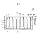
- FIG. 8 is a plan view showing the secondary battery module according to the third embodiment.
- the secondary battery module 1B of the present embodiment is different from the above-described second embodiment in having only one battery block 10.
- the other structure is the same as that of the second embodiment, and a duplicate description will be omitted.
- the secondary battery module 1B includes one battery block 10 and a holding body 20A that holds the battery block 10. For this reason, the holding body 20A does not have the section plate 23 described in the first and second embodiments.
- One of the two module end bus bars 33 (the right module end bus bar 33A in FIG. 8) is provided with a fuse portion 33e.
- the same operation and effect as those of the above-described second embodiment can be obtained.
- the present invention has been described in detail.
- the present invention is not limited to the above embodiments, and various designs may be made without departing from the spirit of the present invention described in the claims. Changes can be made.
- the module external connection terminal 34 may be fixed to an extension of the module end bus bar 33 that extends toward the side plate 22.
Landscapes
- Chemical & Material Sciences (AREA)
- Chemical Kinetics & Catalysis (AREA)
- Electrochemistry (AREA)
- General Chemical & Material Sciences (AREA)
- Inorganic Chemistry (AREA)
- Connection Of Batteries Or Terminals (AREA)
- Battery Mounting, Suspending (AREA)
Abstract
二次電池モジュール1は、複数の電池セル11が積層される電池ブロック10を複数有する。この二次電池モジュール1は、複数の電池ブロック10を挟持し、対向する一対のエンドプレート21と、対向する一対のサイドプレート22と、電池ブロック10同士の間に配置されてこれらの電池ブロック10を仕切るセクションプレート23とを有する挟持体20と、隣接する電池ブロック10同士を電気的に接続し、セクションプレート23を跨いで設けられるブロック間バスバー32とを備える。ブロック間バスバー32には、ヒューズ部32dが設けられている。
Description
本発明は、二次電池モジュールに関する。
本願は、2018年6月22日に出願された日本国特願2018-118425号に基づき優先権を主張し、その内容をここに援用する。
本願は、2018年6月22日に出願された日本国特願2018-118425号に基づき優先権を主張し、その内容をここに援用する。
従来、このような分野の技術として、電池セルを複数積層してなる二次電池モジュールが知られている。このような二次電池モジュールでは、電池セル同士がバスバーによって電気的に接続されている。そして、異常な過電流に起因する電池セルの損傷を防止するために、複数のバスバーのうちの一つにヒューズ部を設ける、いわゆるヒューズ機能付きバスバーが採用されている。
例えば、下記特許文献1に記載の二次電池モジュールでは、他の部分よりも断面積の小さい小断面積部(すなわち、ヒューズ部)を有するヒューズ機能付きバスバーが開示されている。異常な過電流が流れると、発熱により該小断面積部を溶断させることで、電池セルの保護を図っている。
しかし、上述のヒューズ機能付きバスバーは、ヒューズ部が他の部分より肉薄く或いは幅狭く形成されているので、振動や衝撃等の外力が加わった際にヒューズ部に応力集中が生じやすく、ヒューズ部が破断する問題があった。
本発明は、このような技術課題を解決するためになされたものであって、ヒューズ部にかかる応力を低減し、ヒューズ部の破断を抑制できる二次電池モジュールを提供することを目的とする。
本発明に係る二次電池モジュールは、複数の電池セルが積層される電池ブロックを複数有する二次電池モジュールであって、複数の前記電池ブロックを挟持し、対向する一対のエンドプレートと、対向する一対のサイドプレートと、前記電池ブロック同士の間に配置されてこれらの電池ブロックを仕切るセクションプレートとを有する挟持体と、隣接する前記電池ブロック同士を電気的に接続するとともに、前記セクションプレートを跨いで設けられるブロック間バスバーと、を備え、前記ブロック間バスバーには、ヒューズ部が設けられていることを特徴とする。
また、本発明に係る二次電池モジュールは、複数の電池セルが積層される電池ブロックを少なくとも一つ有する二次電池モジュールであって、前記電池ブロックを挟持し、対向する一対のエンドプレートと、対向する一対のサイドプレートとを有する挟持体と、一端部が前記電池ブロックと電気的に接続され、他端部が前記エンドプレート側又は前記サイドプレート側に延設されるとともにモジュール外部接続端子と電気的に接続される複数のモジュール端部バスバーと、を備え、前記複数のモジュール端部バスバーのうち少なくとも一つには、ヒューズ部が設けられていることを特徴とする。
本発明によれば、ヒューズ部にかかる応力を低減し、ヒューズ部の破断を抑制することができる。
以下、図面を参照して本発明に係る二次電池モジュールの実施形態について説明する。図面の説明において同一の要素には同一符号を付し、その重複説明は省略する。なお、下記の説明において、説明の煩雑を避けるために、「電池セルの積層方向」を「積層方向」と省略する場合がある。
[第1実施形態]
図1は第1実施形態に係る二次電池モジュールを示す斜視図であり、図2は第1実施形態に係る二次電池モジュールを示す平面図である。本実施形態の二次電池モジュール1は、主に、複数の電池セル11を一定の方向に積層してなる2つの電池ブロック10と、電池セル11の積層方向に直列に配列した2つの電池ブロック10を挟持する挟持体20とを備えている。
図1は第1実施形態に係る二次電池モジュールを示す斜視図であり、図2は第1実施形態に係る二次電池モジュールを示す平面図である。本実施形態の二次電池モジュール1は、主に、複数の電池セル11を一定の方向に積層してなる2つの電池ブロック10と、電池セル11の積層方向に直列に配列した2つの電池ブロック10を挟持する挟持体20とを備えている。
電池ブロック10は、複数(ここでは、17個)の扁平角形の電池セル11を、間に絶縁樹脂材料からなるセルホルダ(図示せず)を介在させた状態で積層方向に積層することにより構成されている。
図3は電池セルを示す斜視図である。図3に示すように、電池セル11は、電池缶12及び電池蓋13を有する。電池缶12は、いわゆる有底角筒状を呈しており、矩形状に形成された缶底部12aと、缶底部12aの四周から立ち上がるとともに相対的に面積が大きく形成されて互いに対向する一対の幅広側面部12bと、相対的に面積が小さく形成されて互いに対向する一対の幅狭側面部12cとを有する。電池缶12の内部には、例えば扁平状に捲回された電極群及び電解液が収容されている。
電池蓋13は、略矩形状を呈しており、電池缶12の開口部を塞ぐように電池缶12と接合されている。接合方法として、レーザ溶接等が挙げられる。電池蓋13には、正極端子14と負極端子15とが突設されている。正極端子14及び負極端子15は、レーザ溶接でセル間バスバー31、ブロック間バスバー32又はモジュール端部バスバー33(後述する)と接合し易くするために、それぞれの端部が平面状に形成されている。
また、電池蓋13には、ガス排出弁16が設けられている。電池セル11内部の圧力が上昇すると、ガス排出弁16が開いて内部からガスが排出される。これによって、電池セル11内部の圧力が低減されるので、電池セル11の安全性を確保することができる。更に、電池蓋13には、電解液の注液口を塞ぐための注液栓17が設けられている。注液栓17は、例えば注液口を介して電解液を電池セル11内部に充填した後に、レーザ溶接で電池蓋13と接合されている。
このような構造を有する複数の電池セル11は、隣接する一方の電池セル11の正極端子14と他方の電池セル11の負極端子15とが積層方向に隣り合うように交互に180°反転された状態で積層されている。そして、隣接する一方の電池セル11の正極端子14と他方の電池セル11の負極端子15とは、セル間バスバー31によって電気的に接続されている。セル間バスバー31は、例えばアルミニウム材料によって平板状に形成されており、正極端子14及び負極端子15を覆うようにこれらの端子の上に載せられた状態で、レーザ溶接でこれらの端子と接合されている。
挟持体20は、例えば上方に開口する箱状に形成されており、矩形状の底板部24と、該底板部24の四周から立ち上がる一対のエンドプレート21と一対のサイドプレート22と、底板部24、エンドプレート21及びサイドプレート22によって形成された空間の内部に配置されるセクションプレート23とを有する。
一対のエンドプレート21は、互いに対向するように電池セル11の積層方向の両側に配置されている。エンドプレート21は、例えば金属材料によって形成されており、電池セル11の積層方向に直交する方向に延びるとともに、積層方向に所定の幅を有するように構成されている。エンドプレート21には、所定の間隔で離れたネジ孔21aが2つ設けられている。そして、エンドプレート21は、これらのネジ孔21aに挿入されたネジ25(図6参照)によって、底板部24とともに筐体40と締結されている。後述するが、ネジ25はエンドプレート21を筐体40に締結するための締結部材である。
一対のサイドプレート22は、エンドプレート21よりも薄く形成され、積層方向に沿って延設されている。サイドプレート22は、底板部24とともに、例えば一枚の金属板をコ字状に折り曲げることによって一体的に形成されている。なお、サイドプレート22は、例えば底板部24と個別に形成され、溶接やネジ止め等で底板部24と固定されても良い。
一方、セクションプレート23は、電池ブロック10同士を仕切るようにこれらの電池ブロック10の間に配置され、エンドプレート21と平行に設けられている。セクションプレート23は、長方体形状を呈しており、幅の比較的に狭い部分が電池セル11の積層方向に沿うようになっている。このため、図1及び図2に示すように、セクションプレート23の上表面は積層方向に沿う幅狭面23aとなっている。
また、セクションプレート23には、所定の間隔で離れたネジ孔23bが2つ設けられている。該セクションプレート23は、これらのネジ孔23bに挿入されたネジ25(図6参照)によって、底板部24とともに筐体40と締結されている。後述するが、ネジ25はセクションプレート23を筐体40に締結するための締結部材である。
本実施形態の二次電池モジュール1は、上述したセル間バスバー31のほか、隣接する電池ブロック10同士を電気的に接続するブロック間バスバー32と、電池ブロック10における電池セル11の正極端子14又は負極端子15とエンドプレート21の近傍に配置されたモジュール外部接続端子34とを電気的に接続するモジュール端部バスバー33とを更に備えている。
ブロック間バスバー32は、セクションプレート23を跨ぐように設けられており、隣接する電池ブロック10同士の一方の正極端子14と他方の負極端子15とを電気的に接続している。
図4はブロック間バスバーを示す斜視図である。図4に示すように、ブロック間バスバー32は、断面略ハット状を呈しており、隣接する電池ブロック10同士の正極端子14及び負極端子15の一方と接合される平板状の接合部32aと、他方と接合される平板状の接合部32b、接合部32a,32bの間に配置されるとともに電池セル11の外方に突出する突出部32cとを有する。そして、突出部32cの中央には、ブロック間バスバー32の他の部分よりも幅狭く形成されたヒューズ部32dが設けられている。すなわち、ブロック間バスバー32は、ヒューズ機能付きバスバーである。なお、ヒューズ部32dは、セクションプレート23の幅狭面23aに対向するように、突出部32cの中央部分に配置されている。
このような構造を有するブロック間バスバー32は、例えば一枚のアルミニウム板をヒューズ部32dを形成する場所に幅狭く加工した後に、ハット状に折り曲げることによって形成されている。なお、該ブロック間バスバー32は、アルミニウム製の突出部32cと銅製の接合部32a,32bとが接合されたクラッド材によって形成されても良い。
一方、モジュール端部バスバー33は、板状を呈しており、その一端部がエンドプレート21に最も隣接する電池セル11の正極端子14又は負極端子15と電気的に接続され、他端部がエンドプレート21側に延設されるとともにモジュール外部接続端子34と電気的に接続されている。
図5はモジュール端部バスバーを示す斜視図である。図5に示すように、モジュール端部バスバー33は、例えば一枚のアルミニウム板を略Z字状を折り曲げることで形成されており、エンドプレート21に最も隣接する電池セル11の正極端子14又は負極端子15と接合するとともに相対的に高く配置される接合部33a、相対的に低く配置されるとともにエンドプレート21側に延設する延設部33bと、接合部33a及び延設部33bの間に配置される段差部33cとを有する。延設部33bの先端部には、ネジ孔33dが設けられている。上述のモジュール外部接続端子34は、該ネジ孔33dにねじ込まれてモジュール端部バスバー33と固定されている。
モジュール端部バスバー33は、その接合部33aが電池セル11の正極端子14又は負極端子15と溶接されることにより、電池セル11と固定されている。図示しないが、電池セル11と固定された状態において、モジュール端部バスバー33は、延設部33bの底面がエンドプレート21の上面から離れるようになっており、エンドプレート21との電気的な絶縁を確保している。同様に、モジュール端部バスバー33のネジ孔33dにねじ込まれたモジュール外部接続端子34は、その底面がエンドプレート21の上面から離れており、エンドプレート21と電気的に絶縁されている。
このような構造を有するモジュール端部バスバー33は、二次電池モジュール1の積層方向の両側に1箇所ずつ設けられており、すなわち、積層方向の一方側に位置する電池セル11の正極端子14とモジュール外部接続端子34と電気的に接続するものと、積層方向の他方側に位置する電池セル11の負極端子15とモジュール外部接続端子34と電気的に接続するものである。そして、モジュール端部バスバー33を介して電池セル11の正極端子14と電気的に接続されるモジュール外部接続端子34は、二次電池モジュール1のモジュール外部接続端子の正極として機能する。モジュール端部バスバー33を介して電池セル11の負極端子15と電気的に接続されるモジュール外部接続端子34は、二次電池モジュール1のモジュール外部接続端子の負極として機能する。
本実施形態に係る二次電池モジュール1では、ブロック間バスバー32がセクションプレート23を跨いで設けられており、該ブロック間バスバー32にヒューズ部32dが設けられている。セクションプレート23は、挟持体20を構成するものであり、二次電池モジュール1において比較的に強度が強い部分である。このような比較的に強度の強いセクションプレート23の近傍にヒューズ部32dを有するブロック間バスバー32が設けられることで、ヒューズ部32dにかかる応力を低減することができ、振動や衝撃等の外力に起因するヒューズ部32dの破断を抑制することができる。
また、ヒューズ部32dは、セクションプレート23の幅狭面23aと対向するようにブロック間バスバー32に設けられているので、ヒューズ部32dにかかる応力を低減できるとともに、例えばセクションプレート23の幅広面(すなわち、長手方向に延びる面)と対向して設けられる場合と比べて、ブロック間バスバー32の突出部32cを短くすることができる。その結果、ブロック間バスバー32に用いる材料を少なくすることができ、コスト削減を図ることができる。
ここで、挟持体20によって挟持された電池ブロック10を収容する筐体があった場合、ヒューズ部32dの近傍にセクションプレート23を筐体に締結するための締結部材が配置されることが好適である。具体的には、例えば図6に示すよう、二次電池モジュール1は、挟持体20に挟持された電池ブロック10を収容する筐体40を更に有する。筐体40は、箱状を呈しており、その内部には挟持体20に挟持された電池ブロック10が2つ収容されている。なお、図6において蓋を有さない筐体40を示すが、該筐体40は蓋を有するものであっても良い。
図6に示すように、筐体40の底部41には、上述したエンドプレート21のネジ孔21a、セクションプレート23のネジ孔23bと対応するネジ孔41aがそれぞれ設けられている。ネジ孔21aの内壁には内ねじが形成されている。そして、挟持体20に挟持された電池ブロック10は、ネジ孔21a,23bに挿入されて更にネジ孔41aに螺入されたネジ25によって筐体40に締結されている。
このとき、ヒューズ部32dの近傍には、セクションプレート23を筐体40に締結するためのネジ25が配置されている。このようにすれば、ヒューズ部32dにかかる応力を低減する効果を一層向上することができるので、振動や衝撃等の外力に起因するヒューズ部32dの破断を更に抑制することができる。
本実施形態において、ヒューズ部32dがブロック間バスバー32の他の部分よりも幅狭く形成される例を説明したが、該ヒューズ部32dは、ブロック間バスバー32の他の部分と同じ幅を有しつつ、ブロック間バスバー32の他の部分よりも肉薄く形成されても良く、あるいは、ブロック間バスバー32の他の部分よりも幅狭く且つ肉薄く形成されても良い。このようにすれば、必要に応じてヒューズ部32dの態様を変えることで、ヒューズ部32dの汎用性を高めることができるとともに、材料の節約を図り易くなる。
[第2実施形態]
図7は第2実施形態に係る二次電池モジュールを示す平面図である。本実施形態の二次電池モジュール1Aは、2つのモジュール端部バスバー33のうちの1つがヒューズ機能付きバスバーである点において、上述の第1実施形態と異なっている。その他の構造は第1実施形態と同様のため、重複説明を省略する。
図7は第2実施形態に係る二次電池モジュールを示す平面図である。本実施形態の二次電池モジュール1Aは、2つのモジュール端部バスバー33のうちの1つがヒューズ機能付きバスバーである点において、上述の第1実施形態と異なっている。その他の構造は第1実施形態と同様のため、重複説明を省略する。
図7に示すように、ブロック間バスバー32には、ヒューズ部32dが設けられていない。一方、2つのモジュール端部バスバー33のうちの1つ(図7において右側のモジュール端部バスバー33A)には、ヒューズ部33eが設けられている。ヒューズ部33eは、延設部33bにおけるネジ孔33dと段差部33cとの間に形成されており、モジュール端部バスバー33Aの他の部分よりも幅狭くなっている。このモジュール端部バスバー33Aは、例えば一枚のアルミニウム板をヒューズ部33eを形成する場所に幅狭く加工し、且つネジ孔33dを加工した後に、Z字状に折り曲げることによって形成されている。
本実施形態の二次電池モジュール1Aによれば、上述の第1実施形態と同様な作用効果を得られる。すなわち、エンドプレート21は、挟持体20を構成するものであり、二次電池モジュール1において比較的に強度が強い部分である。このような比較的に強度の強いエンドプレート21の近傍にヒューズ部33eを有するモジュール端部バスバー33Aが設けられることで、ヒューズ部33eにかかる応力を低減することができ、振動や衝撃等の外力に起因するヒューズ部33eの破断を抑制することができる。
また、本実施形態において、ヒューズ部33eの近傍にエンドプレート21を筐体40に締結するためのネジ25が配置されることが好ましい。このようにすれば、ヒューズ部33eにかかる応力を低減する効果を更に向上することができる。
なお、本実施形態において、2つのモジュール端部バスバー33のうちの1つがヒューズ機能付きバスバーである例を説明したが、必要に応じて2つのモジュール端部バスバー33ともにヒューズ機能付きバスバーであっても良く、あるいは、2つのモジュール端部バスバー33のうちの1つがヒューズ機能付きバスバーであることに加えて、ブロック間バスバー32もヒューズ機能付きバスバーであっても良い。
[第3実施形態]
図8は第3実施形態に係る二次電池モジュールを示す平面図である。本実施形態の二次電池モジュール1Bは、電池ブロック10を1つのみ有する点において、上述の第2実施形態と異なっている。その他の構造は第2実施形態と同様のため、重複説明を省略する。
図8は第3実施形態に係る二次電池モジュールを示す平面図である。本実施形態の二次電池モジュール1Bは、電池ブロック10を1つのみ有する点において、上述の第2実施形態と異なっている。その他の構造は第2実施形態と同様のため、重複説明を省略する。
図8に示すように、二次電池モジュール1Bは、1つの電池ブロック10と、該電池ブロック10を挟持する挟持体20Aとを備えている。このため、挟持体20Aは、第1及び第2実施形態で述べたセクションプレート23を有さない。そして、2つのモジュール端部バスバー33のうちの一つ(図8において右側のモジュール端部バスバー33A)には、ヒューズ部33eが設けられている。
本実施形態の二次電池モジュール1Bによれば、上述の第2実施形態と同様な作用効果を得られる。
以上、本発明の実施形態について詳述したが、本発明は、上記の実施形態に限定されるものではなく、特許請求の範囲に記載された本発明の精神を逸脱しない範囲で、種々の設計変更を行うことができるものである。例えば、上述の第2及び第3実施形態において、モジュール端部バスバー33がエンドプレート21側に延設する例を説明したが、モジュール端部バスバー33がサイドプレート22側に延設するように形成されても良い。この場合、モジュール外部接続端子34はモジュール端部バスバー33におけるサイドプレート22側に延設する延設部に固定されれば良い。
1,1A,1B 二次電池モジュール
10 電池ブロック
11 電池セル
20,20A 挟持体
21 エンドプレート
21a ネジ孔
22 サイドプレート
23 セクションプレート
23a 幅狭面
23b ネジ孔
24 底板部
25 ネジ(締結部材)
31 セル間バスバー
32 ブロック間バスバー
32a,32b,33a 接合部
32c 突出部
32d,33e ヒューズ部
33,33A モジュール端部バスバー
33b 延設部
33c 段差部
33d ネジ孔
34 モジュール外部接続端子
40 筐体
10 電池ブロック
11 電池セル
20,20A 挟持体
21 エンドプレート
21a ネジ孔
22 サイドプレート
23 セクションプレート
23a 幅狭面
23b ネジ孔
24 底板部
25 ネジ(締結部材)
31 セル間バスバー
32 ブロック間バスバー
32a,32b,33a 接合部
32c 突出部
32d,33e ヒューズ部
33,33A モジュール端部バスバー
33b 延設部
33c 段差部
33d ネジ孔
34 モジュール外部接続端子
40 筐体
Claims (7)
- 複数の電池セルが積層される電池ブロックを複数有する二次電池モジュールであって、
複数の前記電池ブロックを挟持し、対向する一対のエンドプレートと、対向する一対のサイドプレートと、前記電池ブロック同士の間に配置されてこれらの電池ブロックを仕切るセクションプレートとを有する挟持体と、
隣接する前記電池ブロック同士を電気的に接続するとともに、前記セクションプレートを跨いで設けられるブロック間バスバーと、
を備え、
前記ブロック間バスバーには、ヒューズ部が設けられていることを特徴とする二次電池モジュール。 - 前記セクションプレートは、前記電池セルの積層方向に沿う幅狭面を有し、
前記ヒューズ部は、前記セクションプレートの前記幅狭面と対向するように前記ブロック間バスバーに設けられている請求項1に記載の二次電池モジュール。 - 前記ヒューズ部は、前記ブロック間バスバーの他の部分よりも幅狭く又は/及び肉薄く形成されている請求項1又は2に記載の二次電池モジュール。
- 前記挟持体によって挟持された複数の前記電池ブロックを収容する筐体を更に備え、
前記セクションプレートは、締結部材によって前記筐体と締結されており、
前記ヒューズ部の近傍には、前記締結部材が配置されている請求項1~3のいずれか一項に記載の二次電池モジュール。 - 複数の電池セルが積層される電池ブロックを少なくとも一つ有する二次電池モジュールであって、
前記電池ブロックを挟持し、対向する一対のエンドプレートと、対向する一対のサイドプレートとを有する挟持体と、
一端部が前記電池ブロックと電気的に接続され、他端部が前記エンドプレート側又は前記サイドプレート側に延設されるとともにモジュール外部接続端子と電気的に接続される複数のモジュール端部バスバーと、
を備え、
前記複数のモジュール端部バスバーのうち少なくとも一つには、ヒューズ部が設けられていることを特徴とする二次電池モジュール。 - 前記ヒューズ部は、前記モジュール端部バスバーの他の部分よりも幅狭く又は/及び肉薄く形成されている請求項5に記載の二次電池モジュール。
- 前記挟持体によって挟持された前記電池ブロックを収容する筐体を更に備え、
前記エンドプレート又は前記サイドプレートは、締結部材によって前記筐体と締結されており、
前記ヒューズ部の近傍には、前記締結部材が配置されている請求項5又は6に記載の二次電池モジュール。
Priority Applications (7)
| Application Number | Priority Date | Filing Date | Title |
|---|---|---|---|
| JP2020525243A JP6983314B2 (ja) | 2018-06-22 | 2019-02-25 | 二次電池モジュール |
| EP19822527.8A EP3813152A4 (en) | 2018-06-22 | 2019-02-25 | SECONDARY BATTERY MODULE |
| US17/059,976 US11646474B2 (en) | 2018-06-22 | 2019-02-25 | Secondary battery module |
| CN201980035841.7A CN112243549B (zh) | 2018-06-22 | 2019-02-25 | 二次电池模块 |
| CN202410527251.9A CN118448818A (zh) | 2018-06-22 | 2019-02-25 | 二次电池模块 |
| JP2021189207A JP7191184B2 (ja) | 2018-06-22 | 2021-11-22 | 二次電池モジュール |
| US18/194,932 US12315954B2 (en) | 2018-06-22 | 2023-04-03 | Secondary battery module |
Applications Claiming Priority (2)
| Application Number | Priority Date | Filing Date | Title |
|---|---|---|---|
| JP2018-118425 | 2018-06-22 | ||
| JP2018118425 | 2018-06-22 |
Related Child Applications (2)
| Application Number | Title | Priority Date | Filing Date |
|---|---|---|---|
| US17/059,976 A-371-Of-International US11646474B2 (en) | 2018-06-22 | 2019-02-25 | Secondary battery module |
| US18/194,932 Continuation US12315954B2 (en) | 2018-06-22 | 2023-04-03 | Secondary battery module |
Publications (1)
| Publication Number | Publication Date |
|---|---|
| WO2019244402A1 true WO2019244402A1 (ja) | 2019-12-26 |
Family
ID=68983626
Family Applications (1)
| Application Number | Title | Priority Date | Filing Date |
|---|---|---|---|
| PCT/JP2019/007086 Ceased WO2019244402A1 (ja) | 2018-06-22 | 2019-02-25 | 二次電池モジュール |
Country Status (5)
| Country | Link |
|---|---|
| US (2) | US11646474B2 (ja) |
| EP (1) | EP3813152A4 (ja) |
| JP (2) | JP6983314B2 (ja) |
| CN (2) | CN112243549B (ja) |
| WO (1) | WO2019244402A1 (ja) |
Cited By (7)
| Publication number | Priority date | Publication date | Assignee | Title |
|---|---|---|---|---|
| JP2022020832A (ja) * | 2018-06-22 | 2022-02-01 | ビークルエナジージャパン株式会社 | 二次電池モジュール |
| JP2022026170A (ja) * | 2020-07-30 | 2022-02-10 | プライムプラネットエナジー&ソリューションズ株式会社 | 蓄電モジュール |
| US20220328945A1 (en) * | 2021-03-31 | 2022-10-13 | Contemporary Amperex Technology Co., Limited | Bus member, battery and power consumption device |
| CN115485928A (zh) * | 2020-10-23 | 2022-12-16 | 株式会社 Lg新能源 | 包括具有螺纹的汇流条的电池模块 |
| CN116137369A (zh) * | 2021-11-17 | 2023-05-19 | 泰星能源解决方案有限公司 | 电池模块 |
| JP2024508072A (ja) * | 2022-01-25 | 2024-02-22 | 湖北億緯動力有限公司 | バスバーアセンブリ及び円筒動力電池モジュール |
| EP4228083A4 (en) * | 2021-06-14 | 2024-10-30 | LG Energy Solution, Ltd. | BATTERY PACK WITH IMPROVED SAFETY |
Families Citing this family (7)
| Publication number | Priority date | Publication date | Assignee | Title |
|---|---|---|---|---|
| US11545706B2 (en) * | 2018-06-19 | 2023-01-03 | Sk Innovation Co., Ltd. | Battery cell having a plurality of electrodes and battery module using the same |
| DE112019006495T5 (de) * | 2018-12-27 | 2021-09-02 | Gs Yuasa International Ltd. | Energiespeichervorrichtung |
| JP7768726B2 (ja) * | 2021-10-25 | 2025-11-12 | 株式会社東芝 | 電池モジュール |
| CN115000637B (zh) * | 2022-06-22 | 2025-07-18 | 楚能新能源股份有限公司 | 电池包电芯连接件的自动安装机构 |
| KR20240024622A (ko) * | 2022-08-17 | 2024-02-26 | 주식회사 엘지에너지솔루션 | 전지 모듈 및 이를 포함하는 전지팩 |
| WO2024146856A1 (en) * | 2023-01-04 | 2024-07-11 | Volvo Car Corporation | Battery module having two sub-modules |
| EP4730542A1 (en) * | 2024-10-17 | 2026-04-22 | Samsung Sdi Co., Ltd. | Battery module and battery pack including same |
Citations (5)
| Publication number | Priority date | Publication date | Assignee | Title |
|---|---|---|---|---|
| JP2009289431A (ja) * | 2008-05-27 | 2009-12-10 | Keihin Corp | 組電池の電源制御装置 |
| JP2012181977A (ja) * | 2011-03-01 | 2012-09-20 | Mitsubishi Heavy Ind Ltd | 二次電池モジュール |
| JP2013073929A (ja) | 2011-09-29 | 2013-04-22 | Gs Yuasa Corp | 電池パック |
| JP2014229384A (ja) * | 2013-05-20 | 2014-12-08 | 三菱自動車工業株式会社 | バスバー |
| JP2018118425A (ja) | 2017-01-24 | 2018-08-02 | 藤森工業株式会社 | 積層体、ブリスター容器、プレススルーパッケージ、及び積層体の製造方法 |
Family Cites Families (17)
| Publication number | Priority date | Publication date | Assignee | Title |
|---|---|---|---|---|
| JP2003045305A (ja) * | 2001-07-30 | 2003-02-14 | Uchihashi Estec Co Ltd | 薄型ヒューズ |
| JP5105394B2 (ja) * | 2006-03-15 | 2012-12-26 | 日立ビークルエナジー株式会社 | 電池ユニット |
| JP2012138239A (ja) * | 2010-12-27 | 2012-07-19 | Panasonic Corp | 電池モジュール |
| WO2013103244A1 (ko) | 2012-01-03 | 2013-07-11 | 주식회사 엘지화학 | 배터리 팩 및 이에 적용되는 커넥팅 바 |
| US20130252052A1 (en) | 2012-03-21 | 2013-09-26 | GM Global Technology Operations LLC | Integrated Busbar, Terminal Pin And Circuit Protection For Sensing Individual Battery Cell Voltage |
| JP6045802B2 (ja) * | 2012-03-21 | 2016-12-14 | 株式会社東芝 | 二次電池装置 |
| US9912018B2 (en) | 2012-03-21 | 2018-03-06 | GM Global Technology Operations LLC | Integration of a voltage sense trace fuse into a battery interconnect board |
| JP5939007B2 (ja) | 2012-04-13 | 2016-06-22 | トヨタ自動車株式会社 | 蓄電装置 |
| JP6166356B2 (ja) * | 2013-03-28 | 2017-07-19 | 日立オートモティブシステムズ株式会社 | 電池モジュール |
| US20160126514A1 (en) * | 2013-06-19 | 2016-05-05 | Hitachi Automotive Systems, Ltd. | Battery module |
| KR101749721B1 (ko) * | 2014-04-04 | 2017-06-21 | 주식회사 엘지화학 | 퓨즈 어셈블리를 포함하는 전지모듈 어셈블리 |
| DE102015113374B4 (de) | 2014-08-18 | 2023-08-24 | GM Global Technology Operations LLC (n. d. Gesetzen des Staates Delaware) | Anordnung zum erfassen einer spannung, batteriestapel sowie verfahren zum bereitstellen einer elektrischen konnektivität zu einem batteriestapel eines kraftfahrzeugantriebssystems |
| WO2016136249A1 (ja) * | 2015-02-27 | 2016-09-01 | 三洋電機株式会社 | 二次電池及び複数の二次電池を備えた組電池 |
| JP2017123280A (ja) * | 2016-01-07 | 2017-07-13 | トヨタ自動車株式会社 | 電池モジュール |
| CN107305938A (zh) * | 2016-04-25 | 2017-10-31 | 比亚迪股份有限公司 | 电池连接片、电池模组以及动力电池包 |
| US10062977B2 (en) * | 2016-10-14 | 2018-08-28 | Inevit Llc | Module-to-module power connector between battery modules of an energy storage system and arrangement thereof |
| CN112243549B (zh) | 2018-06-22 | 2024-05-24 | 日本汽车能源株式会社 | 二次电池模块 |
-
2019
- 2019-02-25 CN CN201980035841.7A patent/CN112243549B/zh active Active
- 2019-02-25 WO PCT/JP2019/007086 patent/WO2019244402A1/ja not_active Ceased
- 2019-02-25 US US17/059,976 patent/US11646474B2/en active Active
- 2019-02-25 JP JP2020525243A patent/JP6983314B2/ja active Active
- 2019-02-25 EP EP19822527.8A patent/EP3813152A4/en active Pending
- 2019-02-25 CN CN202410527251.9A patent/CN118448818A/zh active Pending
-
2021
- 2021-11-22 JP JP2021189207A patent/JP7191184B2/ja active Active
-
2023
- 2023-04-03 US US18/194,932 patent/US12315954B2/en active Active
Patent Citations (5)
| Publication number | Priority date | Publication date | Assignee | Title |
|---|---|---|---|---|
| JP2009289431A (ja) * | 2008-05-27 | 2009-12-10 | Keihin Corp | 組電池の電源制御装置 |
| JP2012181977A (ja) * | 2011-03-01 | 2012-09-20 | Mitsubishi Heavy Ind Ltd | 二次電池モジュール |
| JP2013073929A (ja) | 2011-09-29 | 2013-04-22 | Gs Yuasa Corp | 電池パック |
| JP2014229384A (ja) * | 2013-05-20 | 2014-12-08 | 三菱自動車工業株式会社 | バスバー |
| JP2018118425A (ja) | 2017-01-24 | 2018-08-02 | 藤森工業株式会社 | 積層体、ブリスター容器、プレススルーパッケージ、及び積層体の製造方法 |
Cited By (15)
| Publication number | Priority date | Publication date | Assignee | Title |
|---|---|---|---|---|
| JP2022020832A (ja) * | 2018-06-22 | 2022-02-01 | ビークルエナジージャパン株式会社 | 二次電池モジュール |
| JP7191184B2 (ja) | 2018-06-22 | 2022-12-16 | ビークルエナジージャパン株式会社 | 二次電池モジュール |
| JP2022026170A (ja) * | 2020-07-30 | 2022-02-10 | プライムプラネットエナジー&ソリューションズ株式会社 | 蓄電モジュール |
| JP7144488B2 (ja) | 2020-07-30 | 2022-09-29 | プライムプラネットエナジー&ソリューションズ株式会社 | 蓄電モジュール |
| JP7490296B2 (ja) | 2020-10-23 | 2024-05-27 | エルジー エナジー ソリューション リミテッド | ネジ山を有するバスバーを含むバッテリーモジュール |
| CN115485928A (zh) * | 2020-10-23 | 2022-12-16 | 株式会社 Lg新能源 | 包括具有螺纹的汇流条的电池模块 |
| US12500312B2 (en) | 2020-10-23 | 2025-12-16 | Lg Energy Solutions, Ltd | Battery module including busbar having screw thread |
| JP2023523278A (ja) * | 2020-10-23 | 2023-06-02 | エルジー エナジー ソリューション リミテッド | ネジ山を有するバスバーを含むバッテリーモジュール |
| US20220328945A1 (en) * | 2021-03-31 | 2022-10-13 | Contemporary Amperex Technology Co., Limited | Bus member, battery and power consumption device |
| US12206138B2 (en) * | 2021-03-31 | 2025-01-21 | Contemporary Amperex Technology (Hong Kong) Limited | Bus member, battery and power consumption device |
| EP4228083A4 (en) * | 2021-06-14 | 2024-10-30 | LG Energy Solution, Ltd. | BATTERY PACK WITH IMPROVED SAFETY |
| CN116137369A (zh) * | 2021-11-17 | 2023-05-19 | 泰星能源解决方案有限公司 | 电池模块 |
| JP2024508072A (ja) * | 2022-01-25 | 2024-02-22 | 湖北億緯動力有限公司 | バスバーアセンブリ及び円筒動力電池モジュール |
| JP7681105B2 (ja) | 2022-01-25 | 2025-05-21 | 湖北億緯動力有限公司 | バスバーアセンブリ及び円筒動力電池モジュール |
| US12489178B2 (en) | 2022-01-25 | 2025-12-02 | Eve Power Co., Ltd. | Busbar assembly and cylindrical power battery module |
Also Published As
| Publication number | Publication date |
|---|---|
| EP3813152A1 (en) | 2021-04-28 |
| CN118448818A (zh) | 2024-08-06 |
| US12315954B2 (en) | 2025-05-27 |
| US20210218114A1 (en) | 2021-07-15 |
| JP7191184B2 (ja) | 2022-12-16 |
| EP3813152A4 (en) | 2022-04-20 |
| JPWO2019244402A1 (ja) | 2021-03-11 |
| CN112243549A (zh) | 2021-01-19 |
| JP6983314B2 (ja) | 2021-12-17 |
| JP2022020832A (ja) | 2022-02-01 |
| US20230238658A1 (en) | 2023-07-27 |
| CN112243549B (zh) | 2024-05-24 |
| US11646474B2 (en) | 2023-05-09 |
Similar Documents
| Publication | Publication Date | Title |
|---|---|---|
| JP7191184B2 (ja) | 二次電池モジュール | |
| CN102696131B (zh) | 电池模组及电池包 | |
| EP2562843B1 (en) | Battery module | |
| CN104064699B (zh) | 蓄电装置 | |
| CN101771163B (zh) | 二次电池模块 | |
| JP6257951B2 (ja) | 電池モジュール | |
| WO2017047683A1 (ja) | 蓄電装置 | |
| JP6629140B2 (ja) | 蓄電モジュール | |
| WO2013098982A1 (ja) | 電池モジュール、電池ブロック、及び、電池パック | |
| JP2014203747A (ja) | 蓄電素子モジュール | |
| JP6390721B2 (ja) | 電池パック | |
| CN111712940A (zh) | 电池模块 | |
| WO2020105502A1 (ja) | 蓄電モジュール | |
| WO2012073440A1 (ja) | 電池モジュール | |
| JPWO2019124109A1 (ja) | バスバー及び電池積層体 | |
| US11563254B2 (en) | Battery module and battery pack | |
| JPWO2018062226A1 (ja) | 電池モジュール、及び電池パック | |
| JP2017111914A (ja) | 電池パック | |
| EP2605310B1 (en) | Secondary battery module | |
| JP7023359B2 (ja) | 電池パック | |
| US12609417B2 (en) | Battery module | |
| JP2016054112A (ja) | 蓄電装置 | |
| JP6353942B2 (ja) | 蓄電装置及び蓄電装置ユニット | |
| WO2021106516A1 (ja) | 蓄電モジュール |
Legal Events
| Date | Code | Title | Description |
|---|---|---|---|
| 121 | Ep: the epo has been informed by wipo that ep was designated in this application |
Ref document number: 19822527 Country of ref document: EP Kind code of ref document: A1 |
|
| ENP | Entry into the national phase |
Ref document number: 2020525243 Country of ref document: JP Kind code of ref document: A |
|
| NENP | Non-entry into the national phase |
Ref country code: DE |
|
| WWE | Wipo information: entry into national phase |
Ref document number: 2019822527 Country of ref document: EP |