WO2019244426A1 - Système de frein - Google Patents
Système de frein Download PDFInfo
- Publication number
- WO2019244426A1 WO2019244426A1 PCT/JP2019/011082 JP2019011082W WO2019244426A1 WO 2019244426 A1 WO2019244426 A1 WO 2019244426A1 JP 2019011082 W JP2019011082 W JP 2019011082W WO 2019244426 A1 WO2019244426 A1 WO 2019244426A1
- Authority
- WO
- WIPO (PCT)
- Prior art keywords
- brake
- contact position
- sensor
- piston
- thrust
- Prior art date
- Legal status (The legal status is an assumption and is not a legal conclusion. Google has not performed a legal analysis and makes no representation as to the accuracy of the status listed.)
- Ceased
Links
Images



Classifications
-
- B—PERFORMING OPERATIONS; TRANSPORTING
- B60—VEHICLES IN GENERAL
- B60T—VEHICLE BRAKE CONTROL SYSTEMS OR PARTS THEREOF; BRAKE CONTROL SYSTEMS OR PARTS THEREOF, IN GENERAL; ARRANGEMENT OF BRAKING ELEMENTS ON VEHICLES IN GENERAL; PORTABLE DEVICES FOR PREVENTING UNWANTED MOVEMENT OF VEHICLES; VEHICLE MODIFICATIONS TO FACILITATE COOLING OF BRAKES
- B60T13/00—Transmitting braking action from initiating means to ultimate brake actuator with power assistance or drive; Brake systems incorporating such transmitting means, e.g. air-pressure brake systems
- B60T13/74—Transmitting braking action from initiating means to ultimate brake actuator with power assistance or drive; Brake systems incorporating such transmitting means, e.g. air-pressure brake systems with electrical assistance or drive
- B60T13/741—Transmitting braking action from initiating means to ultimate brake actuator with power assistance or drive; Brake systems incorporating such transmitting means, e.g. air-pressure brake systems with electrical assistance or drive acting on an ultimate actuator
-
- B—PERFORMING OPERATIONS; TRANSPORTING
- B60—VEHICLES IN GENERAL
- B60T—VEHICLE BRAKE CONTROL SYSTEMS OR PARTS THEREOF; BRAKE CONTROL SYSTEMS OR PARTS THEREOF, IN GENERAL; ARRANGEMENT OF BRAKING ELEMENTS ON VEHICLES IN GENERAL; PORTABLE DEVICES FOR PREVENTING UNWANTED MOVEMENT OF VEHICLES; VEHICLE MODIFICATIONS TO FACILITATE COOLING OF BRAKES
- B60T8/00—Arrangements for adjusting wheel-braking force to meet varying vehicular or ground-surface conditions, e.g. limiting or varying distribution of braking force
- B60T8/17—Using electrical or electronic regulation means to control braking
- B60T8/171—Detecting parameters used in the regulation; Measuring values used in the regulation
-
- B—PERFORMING OPERATIONS; TRANSPORTING
- B60—VEHICLES IN GENERAL
- B60T—VEHICLE BRAKE CONTROL SYSTEMS OR PARTS THEREOF; BRAKE CONTROL SYSTEMS OR PARTS THEREOF, IN GENERAL; ARRANGEMENT OF BRAKING ELEMENTS ON VEHICLES IN GENERAL; PORTABLE DEVICES FOR PREVENTING UNWANTED MOVEMENT OF VEHICLES; VEHICLE MODIFICATIONS TO FACILITATE COOLING OF BRAKES
- B60T1/00—Arrangements of braking elements, i.e. of those parts where braking effect occurs specially for vehicles
- B60T1/02—Arrangements of braking elements, i.e. of those parts where braking effect occurs specially for vehicles acting by retarding wheels
- B60T1/06—Arrangements of braking elements, i.e. of those parts where braking effect occurs specially for vehicles acting by retarding wheels acting otherwise than on tread, e.g. employing rim, drum, disc, or transmission or on double wheels
- B60T1/065—Arrangements of braking elements, i.e. of those parts where braking effect occurs specially for vehicles acting by retarding wheels acting otherwise than on tread, e.g. employing rim, drum, disc, or transmission or on double wheels employing disc
-
- B—PERFORMING OPERATIONS; TRANSPORTING
- B60—VEHICLES IN GENERAL
- B60T—VEHICLE BRAKE CONTROL SYSTEMS OR PARTS THEREOF; BRAKE CONTROL SYSTEMS OR PARTS THEREOF, IN GENERAL; ARRANGEMENT OF BRAKING ELEMENTS ON VEHICLES IN GENERAL; PORTABLE DEVICES FOR PREVENTING UNWANTED MOVEMENT OF VEHICLES; VEHICLE MODIFICATIONS TO FACILITATE COOLING OF BRAKES
- B60T13/00—Transmitting braking action from initiating means to ultimate brake actuator with power assistance or drive; Brake systems incorporating such transmitting means, e.g. air-pressure brake systems
- B60T13/74—Transmitting braking action from initiating means to ultimate brake actuator with power assistance or drive; Brake systems incorporating such transmitting means, e.g. air-pressure brake systems with electrical assistance or drive
- B60T13/746—Transmitting braking action from initiating means to ultimate brake actuator with power assistance or drive; Brake systems incorporating such transmitting means, e.g. air-pressure brake systems with electrical assistance or drive and mechanical transmission of the braking action
-
- B—PERFORMING OPERATIONS; TRANSPORTING
- B60—VEHICLES IN GENERAL
- B60T—VEHICLE BRAKE CONTROL SYSTEMS OR PARTS THEREOF; BRAKE CONTROL SYSTEMS OR PARTS THEREOF, IN GENERAL; ARRANGEMENT OF BRAKING ELEMENTS ON VEHICLES IN GENERAL; PORTABLE DEVICES FOR PREVENTING UNWANTED MOVEMENT OF VEHICLES; VEHICLE MODIFICATIONS TO FACILITATE COOLING OF BRAKES
- B60T17/00—Component parts, details, or accessories of power brake systems not covered by groups B60T8/00, B60T13/00 or B60T15/00, or presenting other characteristic features
- B60T17/18—Safety devices; Monitoring
- B60T17/22—Devices for monitoring or checking brake systems; Signal devices
-
- B—PERFORMING OPERATIONS; TRANSPORTING
- B60—VEHICLES IN GENERAL
- B60T—VEHICLE BRAKE CONTROL SYSTEMS OR PARTS THEREOF; BRAKE CONTROL SYSTEMS OR PARTS THEREOF, IN GENERAL; ARRANGEMENT OF BRAKING ELEMENTS ON VEHICLES IN GENERAL; PORTABLE DEVICES FOR PREVENTING UNWANTED MOVEMENT OF VEHICLES; VEHICLE MODIFICATIONS TO FACILITATE COOLING OF BRAKES
- B60T17/00—Component parts, details, or accessories of power brake systems not covered by groups B60T8/00, B60T13/00 or B60T15/00, or presenting other characteristic features
- B60T17/18—Safety devices; Monitoring
- B60T17/22—Devices for monitoring or checking brake systems; Signal devices
- B60T17/221—Procedure or apparatus for checking or keeping in a correct functioning condition of brake systems
-
- F—MECHANICAL ENGINEERING; LIGHTING; HEATING; WEAPONS; BLASTING
- F16—ENGINEERING ELEMENTS AND UNITS; GENERAL MEASURES FOR PRODUCING AND MAINTAINING EFFECTIVE FUNCTIONING OF MACHINES OR INSTALLATIONS; THERMAL INSULATION IN GENERAL
- F16D—COUPLINGS FOR TRANSMITTING ROTATION; CLUTCHES; BRAKES
- F16D66/00—Arrangements for monitoring working conditions, e.g. wear, temperature
- F16D66/02—Apparatus for indicating wear
- F16D66/021—Apparatus for indicating wear using electrical detection or indication means
- F16D66/022—Apparatus for indicating wear using electrical detection or indication means indicating that a lining is worn to minimum allowable thickness
- F16D66/023—Apparatus for indicating wear using electrical detection or indication means indicating that a lining is worn to minimum allowable thickness directly sensing the position of braking members
-
- B—PERFORMING OPERATIONS; TRANSPORTING
- B60—VEHICLES IN GENERAL
- B60T—VEHICLE BRAKE CONTROL SYSTEMS OR PARTS THEREOF; BRAKE CONTROL SYSTEMS OR PARTS THEREOF, IN GENERAL; ARRANGEMENT OF BRAKING ELEMENTS ON VEHICLES IN GENERAL; PORTABLE DEVICES FOR PREVENTING UNWANTED MOVEMENT OF VEHICLES; VEHICLE MODIFICATIONS TO FACILITATE COOLING OF BRAKES
- B60T2270/00—Further aspects of brake control systems not otherwise provided for
- B60T2270/40—Failsafe aspects of brake control systems
- B60T2270/406—Test-mode; Self-diagnosis
Definitions
- the present invention relates to a brake system mounted on a vehicle such as an automobile for braking the rotation of wheels.
- a vehicle such as an automobile is equipped with a brake system that applies a braking force to wheels according to the amount of depression of a brake pedal by a driver.
- brake system that applies a braking force to wheels according to the amount of depression of a brake pedal by a driver.
- brake systems Conventionally, many brake systems have been hydraulic systems, but recently, electric systems have been increasing.
- the brake piston can be pulled back, which was difficult with a hydraulic system.
- This allows clearance control to provide a desired gap between the brake pad and the brake disk, and improves fuel efficiency by reducing drag on the brake pad. Can be expected.
- it is sufficient to simply increase the gap at the time of non-braking to simply improve the fuel efficiency, but if it is desired to speed up the braking response at the time of depressing the brake pedal, the gap at the time of non-braking should be as small as possible. It is desirable to keep it narrow.
- a technique for accurately grasping the contact position between the brake pad and the brake disc is important in optimizing the clearance control. Techniques related to this are, for example, those described in Patent Documents 1 to 3.
- Patent Document 1 discloses an “electric disc brake device” that includes a piston that moves linearly along the axis of a disc, a brake pad that is pressed by the piston and contacts the disc, a thrust sensor that detects a piston thrust received by the piston, and a piston displacement. It has a position detector that detects the piston position, and when the value detected by the thrust sensor reaches a predetermined amount when the piston advances, it is determined that the disk has been pressed, and the piston position at that time is set as the contact position between the brake pad and the disk The configuration is shown.
- the "braking device” of Patent Document 3 discloses a position in which the piston is returned to the brake releasing side by a predetermined amount from the piston position at the time when the piston thrust falls below a predetermined threshold value greater than 0 when the brake is released.
- the configuration for setting the contact position of the brake pad is shown.
- Patent Document 1 the detection accuracy of the contact position can be improved by reducing the detection threshold of the thrust sensor.
- a thrust sensor has a characteristic that detection accuracy of a thrust value rapidly deteriorates near a thrust of 0. Therefore, a detection threshold value is required to be larger than a predetermined value. There is a lower limit. As a result, the detection accuracy of the contact position of the brake pad is limited, so that the brake pad drag during non-braking may remain in the method of Patent Document 1.
- Patent Literature 2 the contact position is detected from the rate of change of the output value of the pressure sensor, and the change at the start of boosting can be easily detected as compared with Patent Literature 1 in which the output value of the thrust sensor is directly used. Can be detected with high accuracy.
- Patent Literature 2 when the differential value of the thrust sensor is used as in Patent Literature 2, there is a problem that erroneous detection due to sensor noise easily occurs and reliability is low.
- the contact position is estimated by calculating the amount of change in piston thrust with respect to the change in piston position using two measurement points when the brake is released. 2 problem is avoided.
- Patent Document 3 does not consider the delay time when the output signal of each sensor is subjected to the filter processing, the communication processing, and the arithmetic processing. Therefore, when the output signal of each sensor has a delay time difference, In the microcomputer, output signals detected at different timings are processed as a set of information, so that a position error necessarily occurs between the estimated contact position and the original contact position. . As a result, if the clearance control is executed by relying on the estimated contact position, the clearance may be too small and the brake pad may be dragged during non-braking, or the clearance may become too large and the responsiveness during braking may deteriorate. There is.
- the present invention has been made in view of the above-described problems, and corrects an estimation error of a contact position due to a delay time difference between output signals of respective sensors to accurately determine an actual contact position between a brake pad and a brake disc.
- An object of the present invention is to provide a brake system that can appropriately control a clearance amount by estimating, improve fuel efficiency by preventing drag of a brake pad during non-braking, and shorten response time during braking.
- a brake system includes a brake disc that rotates with wheels, a brake pad that applies a braking force to the brake disc, a piston that drives the brake pad, and a drive force that applies a driving force to the piston.
- a drive mechanism a position sensor that detects the position of the piston, a thrust sensor that detects a thrust that the brake pad presses the brake disc, and a brake control unit that controls the drive mechanism to adjust the braking force.
- a contact position calculation unit that calculates a contact position at which the brake pad and the brake disk make contact based on output signals of the position sensor and the thrust sensor; and the position sensor and the thrust force.
- a position error for calculating a position error of the contact position based on a delay time difference between sensor output signals; A calculation unit, by using the position error, and shall and a contact position correcting unit for correcting the contact position where the contact position calculating unit has determined.
- FIG. 1 is a schematic diagram of a brake system according to a first embodiment.
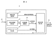
- FIG. 3 is a functional block diagram of a contact position estimating unit according to the first embodiment.
- 5 is a flowchart illustrating a contact position estimation method according to the first embodiment.
- FIG. 4 is a conceptual diagram illustrating a correction operation of a contact position calculation value according to the first embodiment.
- FIG. 9 is a functional block diagram of a contact position estimating unit according to the second embodiment.
- FIG. 13 is a functional block diagram of a contact position estimating unit according to the third embodiment.
- Embodiment 1 A brake system according to Embodiment 1 of the present invention will be described with reference to FIGS.
- FIG. 1 is a schematic diagram of the brake system of the present embodiment, showing a configuration corresponding to an electric brake for one of a plurality of wheels provided in a vehicle.
- the brake system 1 of the present embodiment generally includes a drive mechanism 2, a brake control device 10, a brake mechanism 11, and a rotation / linear motion conversion mechanism 12.
- the drive mechanism 2 includes an electric motor 2a and a speed reducer 2b
- the brake control device 10 includes a motor control unit 3 and a contact position estimation unit 4
- the brake mechanism 11 includes a brake pad 11a and a brake disk.
- the rotation / linear motion conversion mechanism 12 has a rod-like shape including a piston 12a and a feed screw 12b.
- the rotational driving force generated by the electric motor 2a is reduced by the speed reducer 2b, and the rotational driving force after the deceleration is converted into a linear driving force via the feed screw 12b, and the linear driving of the piston 12a is performed.
- a braking force is applied to the rotating brake disc 11b.
- the direction in which the piston 12a approaches the brake disc 11b is defined as a positive direction, and the opposite direction is defined as a negative direction.
- the motor control unit 3 in the brake control device 10 controls the rotation of the electric motor 2a and adjusts the pressing force of the brake pad 11a. Further, the brake control device 10 estimates the braking force of the brake pad 11a based on the thrust detected by the thrust sensor 31 installed on the rotation / linear motion conversion mechanism 12. Further, the brake control device 10 estimates the position of the brake pad 11a based on the rotation position detected by the position sensor 32 installed on the electric motor 2a.
- the position sensor 32 may be attached to the piston 12a so that the position of the piston 12a can be directly detected.
- control signal line 21, the communication lines 22, 23, and the main power line 26 are connected to the brake control device 10.
- the internal motor control unit 3 and the contact position estimation unit 4 are connected to each other by communication lines 24 and 25.
- the control signal line 21 is for inputting a control command from a host control device such as an ECU to the brake control device 10, and the communication lines 22 and 23 communicate information other than the control command with the host control device. Is what you do.
- the host controller and the brake controller 10 are separate here, they may be integrated into a controller.
- the contact position estimating unit 4 includes a contact position calculating unit 40, a delay time difference holding unit 41, a position error calculating unit 42, an apply / release determining unit 43, and a contact position correcting unit 44.
- a signal is input from the motor control unit 3 via the communication line 24, and a signal is output to the motor control unit 3 via the communication line 25.
- the actual contact position estimating unit 4 includes a CPU, an arithmetic device such as a microcomputer, a main storage device such as a semiconductor memory, an auxiliary storage device such as a hard disk, and hardware such as a communication device.
- the contact position calculation unit 40 moves the piston 12a to the brake disk 11b side, and the position of the piston 12a at the moment when the brake pad 11a and the brake disk 11b come into contact with each other and the gap between them becomes zero, that is, the origin of the piston 12a The position is obtained by calculation.
- the contact position calculator 40 calculates a two-dimensional relationship between the thrust of the brake pad 11a and the position of the piston 12a based on detection signals of the thrust sensor 31 and the position sensor 32, which are input momentarily at a predetermined sampling cycle. Plotted in space, based on the change rate of any two points on the obtained curve (for example, two points corresponding to threshold values T high and T low predetermined in consideration of the performance of the thrust sensor 31). To calculate the origin position of the piston 12a (see FIG. 4 described later). The origin position calculated here (hereinafter, referred to as “contact position calculation value X 1 ”) is transmitted to a contact position correction unit 44 described later.
- the delay time difference holding unit 41 outputs a delay time difference ⁇ t between the output signals of the thrust sensor 31 and the position sensor 32, which is generated by performing a filtering process, a communication process, or an arithmetic process. .
- the delay time difference holding unit 41 only needs to be able to output the relative delay time difference ⁇ t between the thrust sensor 31 and the position sensor 32. Therefore, it is not always necessary to hold the delay time information of both sensors as a constant in advance. Instead, the delay time difference ⁇ t of the thrust sensor, which is observed when the piston 12a performs an arbitrary operation, may be learned and output.
- ⁇ Position error calculator 42 The position error calculation unit 42 uses the delay time difference ⁇ t output from the delay time difference holding unit 41 and the speed of the piston 12a obtained by performing time differentiation or the like on the output signal of the position sensor 32, and causes the delay time difference ⁇ t.
- the position error ⁇ Xerr of the piston 12a is calculated.
- the position error ⁇ Xerr calculated here is transmitted to a contact position correction unit 44 described later.
- the apply / release determining unit 43 determines whether the operation at the time of contact position estimation is an apply (increase) operation or a release (decrease) operation.
- ⁇ Contact position correction unit 44 In the contact position correcting unit 44, and the contact position calculated value X 1 from the contact position calculating section 40, by using the position error ⁇ Xerr from the position error calculation unit 42, the operation information from the Apply release determining unit 43, the correcting the estimation error due to the delay time difference ⁇ t of the sensor, and outputs a contact position correction value X 2.
- step S10 it is determined whether the vehicle is currently in a braking state. This determination can be made based on whether the driver depresses the brake pedal to a predetermined amount or more and the thrust command value is 0 or more.
- the process of estimating the contact position cannot be executed, and the process ends and waits for the next start timing.
- the process proceeds to the next step S11.
- step S11 the thrust of the brake pad 11a is detected from the output of the thrust sensor 31 installed in the rotation / linear motion conversion mechanism 12.
- the motor rotation position is detected from the output of the position sensor 32 installed on the electric motor 2a, and the motor rotation speed is detected based on the time derivative.
- step S12 the obtained motor rotational position is converted into a linear motion direction according to the ratio of the rotational linear motion as in (Equation 1).
- the motor speed is also converted to a speed in the direction of direct movement of the piston.
- Xp ⁇ ⁇ (L / ⁇ ) [mm] (Equation 1)
- Xp is the piston position [mm]
- ⁇ is the motor rotation position [rev]
- L is the lead [mm / rev] of the feed screw 12b
- ⁇ is the reduction ratio of the reduction gear 2b.
- Step S13 is one that corresponds to the processing of the main contact position calculating section 40 calculates the origin position of the piston 12a when the brake pad 11a and the brake disc 11b are in contact (contact position calculation value X 1). As described above, there are various methods of calculating the origin position.
- Step S14 mainly corresponds to the processing in the position error calculation unit 42, and uses the representative piston speed Vp and the mutual delay time difference ⁇ t between the thrust sensor 31 and the position sensor 32 acquired from the delay time difference holding unit 41.
- the position error ⁇ Xerr is calculated from (Equation 2).
- Equation 2 the representative piston speed Vp should originally be the speed at the time of contact with the brake pad 11a, but it is impossible to know the piston speed at the true contact position before the completion of the estimation of the contact position according to FIG. since it is, piston velocity, as shown in (equation 3), the average value of the piston velocity two points used in the calculation of the contact position calculated value X 1 (Vp1, Vp2) at step S13, the true contact position Is assumed to be substantially equal to the representative piston speed Vp.
- the representative piston speed Vp (Vp1 + Vp2) / 2 (Equation 3)
- the representative piston speed Vp may be estimated as the representative piston speed Vp by estimating the speed at which the thrust value becomes zero from the thrust values of the two points handled in step S13 and the rate of change of the piston speed.
- the position error ⁇ Xerr is calculated from (Equation 2) using any one of the representative piston speeds Vp
- the process proceeds to step S15.
- ⁇ Step S15 ⁇ Step S15 is intended mainly corresponds to the processing by the Apply release determining unit 43, the contact position calculated value X 1 in the step S13, the apply time, or is calculated on the basis of the data acquired at any release period Is determined.
- step S15 the determination result of step S15 is a position error ⁇ Xerr from the transition contact position calculated value X 1 in step S16 is subtracted when a "Apply", obtaining the contact position correction value X 2.
- step S17 the determination result of step S15 is a position error ⁇ Xerr from the transition contact position calculated value X 1 in step S16 is subtracted when a "Apply", obtaining the contact position correction value X 2.
- step S15 adds the position error ⁇ Xerr Migrated contact position calculated value X 1 in step S17 when the determination result in step S15 is "release", obtaining the contact position correction value X 2.
- the horizontal axis is the position of the piston 12a
- the vertical axis is the thrust of the brake pad 11a
- the intersection of the two axes is the true piston position (the origin position), which is the position of the piston 12a at the moment when the brake pad 11a contacts the brake disc 11b. ).
- the solid curve indicates the true relationship between the thrust of the brake pad 11a and the piston position.
- the thrust of the brake pad 11a increases when the piston 12a moves in the positive direction (left direction in FIG. 1), and the thrust remains zero even when the piston 12a moves in the negative direction (right direction in FIG. 1). A relationship has been established.
- the dashed-dotted line shows the thrust characteristics of the system in which the thrust sensor 31 has a delay with respect to the position sensor 32 at the time of application.
- the increase in the thrust detected by the thrust sensor 31 is delayed with respect to the increase in the position detected by the position sensor 32. Therefore, the contact position calculation unit 40 recognizes a characteristic like a one-dot chain line.
- the two-dot chain line shows the thrust characteristics at the time of release of a system in which the thrust sensor 31 has a delay with respect to the position sensor 32.
- the contact position calculation unit 40 recognizes a characteristic like a two-dot chain line. I do.
- the curve of one-dot chain line corresponding to the time applied to the example illustrates an example of a method of calculating the contact position calculated value X 1 at the contact position calculating section 40 (corresponding Patent Document 3).
- the contact position calculated value X 1 is added to the position error ⁇ Xerr to perform a correction in consideration of the delay time difference ⁇ t of each sensor, and the corrected contact position correction value X 2 (solid white line) closer to the true contact position than the contact position calculation value X 1 (Circle) can be obtained.
- the position error ⁇ Xerr changes depending on the piston speed at the time of contact with the brake pad 11a, and the position error ⁇ Xerr increases as the piston speed increases.
- the representative piston speed Vp of (Equation 3) is used in the calculation of the position error ⁇ Xerr.
- the contact speed is high, the position error ⁇ Xerr increases, and when the contact speed is low, the position error ⁇ Xerr decreases. . That is, since the position error ⁇ Xerr obtained by (Equation 2) takes into account the representative piston speed Vp, the contact position correction value X 2 ( Solid line white circle) can be obtained.
- Example 2 which includes a contact position estimation unit 4 for determining the contact position correction value X 2 by a method different from the first embodiment, as shown in FIG. 5, the same contact position calculating unit as in Example 1 40, a delay time difference holding unit 41, an apply / release determination unit 43, and a contact position correction unit 44, and a piston position time series information holding unit 45.
- the piston position time series information holding unit 45 added in the present embodiment is for recording the time series change of the piston position at the time of application or release in the RAM area of the microcomputer, and the contact position calculation unit 40 calculates the contact position. from the time of calculation of the value X 1, reads the piston position information of the time going back by the delay time difference ⁇ t of the sensors from the RAM, contact close to the true home position by correcting a contact position calculated value X 1 using the same position obtain the corrected value X 2.
- a contact position correction value X 2 close to the true home position based on the time series data is actually recorded.
- drag can be reduced to the brake pad 11a during non-braking, it is possible to enhance the responsiveness of braking.
- Example 3 is one having the contact position estimation unit 4 for determining the contact position correction value X 2 by a method different from the first embodiment, as shown in FIG. 6, the contact in the same manner as in Example 1.
- the synchronization correcting unit 46 of the present embodiment synchronizes the signals of the thrust sensor 31 and the position sensor 32 input via the communication line 24 based on the delay time difference ⁇ t input from the delay time difference holding unit 41. For example, when the detection result of the thrust sensor 31 is delayed by 1 [ms] with respect to the detection result of the position sensor 32, the information of the position sensor 32 after 1 [ms] is associated with the current value of the thrust sensor 31. By processing as a set of data, the effect of the time lag existing between the output values of the sensors can be canceled.
- the contact position close to the true origin position of the piston 12a is obtained as in the above-described embodiment. It is possible to obtain the position correction value X 2. Further, with the use of contact position correction value X 2, similar to the above-described embodiment, it is possible to reduce the drag of the brake pad 11a during non-braking, it is possible to enhance the responsiveness of braking.
- Position sensor Reference numeral 40 contact position calculation unit, 41: delay time difference holding unit, 42: position error calculation unit, 43: apply / release determination unit, 44: contact position correction unit, 45: piston position time series information holding unit, 46: synchronization correction Section, X 1 ... contact position calculation value, X 2 ... contact position correction value
Landscapes
- Engineering & Computer Science (AREA)
- Mechanical Engineering (AREA)
- Transportation (AREA)
- General Engineering & Computer Science (AREA)
- Braking Arrangements (AREA)
- Braking Systems And Boosters (AREA)
- Regulating Braking Force (AREA)
Abstract
Le problème abordé par la présente invention est qu'une erreur d'estimation de position de contact provoquée par des différences de temps de retard entre des signaux de sortie provenant de divers capteurs doit être corrigée afin de commander de manière appropriée la quantité de jeu, et qu'il est souhaitable d'améliorer l'efficacité du carburant en empêchant le glissement d'un patin de frein pendant un état de non-freinage ainsi que de raccourcir un temps de réponse pendant un état de freinage. Ce système de frein comprend: un disque de frein; un patin de frein; un piston; un mécanisme d'entraînement; un capteur de position qui détecte la position du piston; un capteur de poussée qui détecte une force de poussée avec laquelle le patin de frein est pressé contre le disque de frein; et une unité de commande de frein qui commande le mécanisme d'entraînement pour ajuster la force de freinage. L'unité de commande de frein comprend: une unité de calcul de position de contact qui calcule une position de contact où le patin de frein et le disque de frein sont en contact l'un avec l'autre sur la base de signaux de sortie provenant du capteur de position et du capteur de poussée; une unité de calcul d'erreur de position qui calcule une erreur de position dans la position de contact sur la base de différences de temps de retard entre les signaux de sortie provenant du capteur de position et du capteur de poussée; et une unité de correction de position de contact qui utilise l'erreur de position pour corriger la position de contact calculée par l'unité de calcul de position de contact.
Priority Applications (3)
| Application Number | Priority Date | Filing Date | Title |
|---|---|---|---|
| US17/055,515 US11958459B2 (en) | 2018-06-18 | 2019-03-18 | Brake system |
| CN201980030913.9A CN112236342B (zh) | 2018-06-18 | 2019-03-18 | 刹车系统 |
| EP19822195.4A EP3808618B1 (fr) | 2018-06-18 | 2019-03-18 | Système de frein |
Applications Claiming Priority (2)
| Application Number | Priority Date | Filing Date | Title |
|---|---|---|---|
| JP2018115135A JP7074577B2 (ja) | 2018-06-18 | 2018-06-18 | ブレーキシステム |
| JP2018-115135 | 2018-06-18 |
Publications (1)
| Publication Number | Publication Date |
|---|---|
| WO2019244426A1 true WO2019244426A1 (fr) | 2019-12-26 |
Family
ID=68983914
Family Applications (1)
| Application Number | Title | Priority Date | Filing Date |
|---|---|---|---|
| PCT/JP2019/011082 Ceased WO2019244426A1 (fr) | 2018-06-18 | 2019-03-18 | Système de frein |
Country Status (5)
| Country | Link |
|---|---|
| US (1) | US11958459B2 (fr) |
| EP (1) | EP3808618B1 (fr) |
| JP (1) | JP7074577B2 (fr) |
| CN (1) | CN112236342B (fr) |
| WO (1) | WO2019244426A1 (fr) |
Cited By (1)
| Publication number | Priority date | Publication date | Assignee | Title |
|---|---|---|---|---|
| CN114148307A (zh) * | 2020-09-07 | 2022-03-08 | 三菱电机株式会社 | 电动制动器的控制装置 |
Families Citing this family (7)
| Publication number | Priority date | Publication date | Assignee | Title |
|---|---|---|---|---|
| DE102017210893A1 (de) * | 2017-06-28 | 2019-01-03 | Robert Bosch Gmbh | Verfahren und eine Vorrichtung zum Betreiben einer automatisierten Feststellbremse |
| DE102019100183A1 (de) * | 2019-01-07 | 2020-07-09 | Wabco Europe Bvba | Verfahren zum Ermitteln eines Lüftspiels einer elektromechanischen Bremse sowie betreffende Bremse und Steuergerät |
| DE102019100481A1 (de) * | 2019-01-10 | 2020-07-16 | Wabco Europe Bvba | Verfahren zum Einstellen eines Lüftspiels einer elektromechanischen Bremse sowie betreffende Bremse und Steuergerät |
| IT202100012968A1 (it) * | 2021-05-19 | 2022-11-19 | Brembo Spa | Impianto frenante con freni a disco di tipo brake-by-wire, dotato di regolazione dinamica della distanza tra il disco freno e le pastiglie e relativo metodo di regolazione della distanza tra il disco freno e le pastiglie in un impianto frenante di tipo brake-by-wire |
| KR20230021396A (ko) * | 2021-08-05 | 2023-02-14 | 현대모비스 주식회사 | 전동식 브레이크 및 이의 제어방법 |
| JP2023151407A (ja) * | 2022-03-31 | 2023-10-16 | シャープディスプレイテクノロジー株式会社 | タッチパネルシステム、表示装置およびタッチパネルの制御方法 |
| JPWO2025009425A1 (fr) * | 2023-07-05 | 2025-01-09 |
Citations (4)
| Publication number | Priority date | Publication date | Assignee | Title |
|---|---|---|---|---|
| JP2000018294A (ja) | 1998-07-02 | 2000-01-18 | Sumitomo Electric Ind Ltd | 車両用ブレーキ装置 |
| JP2004124950A (ja) | 2002-07-31 | 2004-04-22 | Tokico Ltd | ブレーキ装置 |
| JP2008133922A (ja) | 2006-11-29 | 2008-06-12 | Hitachi Ltd | 電動ディスクブレーキ装置 |
| JP2012159134A (ja) * | 2011-01-31 | 2012-08-23 | Hitachi Automotive Systems Ltd | 電動ブレーキ装置 |
Family Cites Families (8)
| Publication number | Priority date | Publication date | Assignee | Title |
|---|---|---|---|---|
| JP3936210B2 (ja) * | 2001-10-22 | 2007-06-27 | 株式会社日立製作所 | 電動ディスクブレーキおよびその制御プログラム |
| JP2007253655A (ja) * | 2006-03-20 | 2007-10-04 | Toyota Motor Corp | ブレーキ制御装置 |
| JP5582293B2 (ja) * | 2010-03-31 | 2014-09-03 | 日立オートモティブシステムズ株式会社 | 電動ブレーキ装置 |
| JP6248588B2 (ja) * | 2013-12-05 | 2017-12-20 | 株式会社アドヴィックス | 車両の電動制動装置 |
| JP6338902B2 (ja) * | 2014-03-24 | 2018-06-06 | Ntn株式会社 | 電動ブレーキ装置および電動ブレーキ装置システム |
| JP6392895B2 (ja) | 2014-12-27 | 2018-09-19 | 日立オートモティブシステムズ株式会社 | ブレーキ装置 |
| JP6392976B2 (ja) * | 2015-03-31 | 2018-09-19 | 日立オートモティブシステムズ株式会社 | ブレーキ制御装置 |
| KR101836628B1 (ko) | 2016-05-03 | 2018-03-08 | 현대자동차주식회사 | 전동식 브레이크 장치 및 그 제어 방법 |
-
2018
- 2018-06-18 JP JP2018115135A patent/JP7074577B2/ja active Active
-
2019
- 2019-03-18 EP EP19822195.4A patent/EP3808618B1/fr active Active
- 2019-03-18 US US17/055,515 patent/US11958459B2/en active Active
- 2019-03-18 WO PCT/JP2019/011082 patent/WO2019244426A1/fr not_active Ceased
- 2019-03-18 CN CN201980030913.9A patent/CN112236342B/zh active Active
Patent Citations (4)
| Publication number | Priority date | Publication date | Assignee | Title |
|---|---|---|---|---|
| JP2000018294A (ja) | 1998-07-02 | 2000-01-18 | Sumitomo Electric Ind Ltd | 車両用ブレーキ装置 |
| JP2004124950A (ja) | 2002-07-31 | 2004-04-22 | Tokico Ltd | ブレーキ装置 |
| JP2008133922A (ja) | 2006-11-29 | 2008-06-12 | Hitachi Ltd | 電動ディスクブレーキ装置 |
| JP2012159134A (ja) * | 2011-01-31 | 2012-08-23 | Hitachi Automotive Systems Ltd | 電動ブレーキ装置 |
Non-Patent Citations (1)
| Title |
|---|
| See also references of EP3808618A4 |
Cited By (3)
| Publication number | Priority date | Publication date | Assignee | Title |
|---|---|---|---|---|
| CN114148307A (zh) * | 2020-09-07 | 2022-03-08 | 三菱电机株式会社 | 电动制动器的控制装置 |
| CN114148307B (zh) * | 2020-09-07 | 2024-04-02 | 三菱电机株式会社 | 电动制动器的控制装置 |
| US12071112B2 (en) | 2020-09-07 | 2024-08-27 | Mitsubishi Electric Corporation | Electric-brake control apparatus |
Also Published As
| Publication number | Publication date |
|---|---|
| CN112236342A (zh) | 2021-01-15 |
| US11958459B2 (en) | 2024-04-16 |
| EP3808618A4 (fr) | 2022-03-09 |
| JP2019217836A (ja) | 2019-12-26 |
| EP3808618B1 (fr) | 2022-11-23 |
| EP3808618A1 (fr) | 2021-04-21 |
| JP7074577B2 (ja) | 2022-05-24 |
| CN112236342B (zh) | 2022-11-18 |
| US20210197777A1 (en) | 2021-07-01 |
Similar Documents
| Publication | Publication Date | Title |
|---|---|---|
| WO2019244426A1 (fr) | Système de frein | |
| US8833526B2 (en) | Electric brake apparatus | |
| JP4033281B2 (ja) | 制動装置 | |
| CN102791545B (zh) | 车辆状态运算装置以及车辆控制装置 | |
| US9963133B2 (en) | Method for controlling braking force of brake devices for two-wheeled vehicle, and device for controlling braking force | |
| KR20110026928A (ko) | 노면 판단 방법 | |
| KR102537870B1 (ko) | 브레이크 제어 장치 및 브레이크 시스템 | |
| Li et al. | Clamping force control of electro–mechanical brakes based on driver intentions | |
| US12409817B2 (en) | Brake control device and brake control method | |
| EP2915709B1 (fr) | Procédé de commutation de la vitesse de référence d'un véhicule dans un système abs à un seul canal pour motocycle | |
| US7681962B2 (en) | Method for estimating master cylinder pressure during brake apply | |
| US20250178577A1 (en) | Brake device for vehicle | |
| JP6530585B2 (ja) | 制駆動力制御装置及び制駆動力制御方法 | |
| KR20130138011A (ko) | 전동식 부스터 제동장치를 이용한 감속도 제어 방법 및 그 제어 장치 | |
| CN119037376B (zh) | 电子机械制动系统的制动间隙和夹紧力控制方法及系统 | |
| JP2005069268A (ja) | 電動ブレーキ装置 | |
| JP7402847B2 (ja) | 車両用制御装置 | |
| CN117262211A (zh) | 基于减速率控制的飞机刹车控制方法、系统以及介质 | |
| CN115465243A (zh) | 线控制动方法、装置以及电子设备、车辆 | |
| CN119773698A (zh) | 制动力矩估算方法、装置、设备、存储介质及程序产品 | |
| JP2007245767A (ja) | 制動制御装置、自動車及び制動制御方法 |
Legal Events
| Date | Code | Title | Description |
|---|---|---|---|
| 121 | Ep: the epo has been informed by wipo that ep was designated in this application |
Ref document number: 19822195 Country of ref document: EP Kind code of ref document: A1 |
|
| NENP | Non-entry into the national phase |
Ref country code: DE |
|
| ENP | Entry into the national phase |
Ref document number: 2019822195 Country of ref document: EP Effective date: 20210118 |