WO2019244602A1 - Machine à stratifier et procédé de réglage d'alignement de machine à stratifier - Google Patents
Machine à stratifier et procédé de réglage d'alignement de machine à stratifier Download PDFInfo
- Publication number
- WO2019244602A1 WO2019244602A1 PCT/JP2019/021757 JP2019021757W WO2019244602A1 WO 2019244602 A1 WO2019244602 A1 WO 2019244602A1 JP 2019021757 W JP2019021757 W JP 2019021757W WO 2019244602 A1 WO2019244602 A1 WO 2019244602A1
- Authority
- WO
- WIPO (PCT)
- Prior art keywords
- roller
- tip
- laminator
- vacuum
- input
- Prior art date
- Legal status (The legal status is an assumption and is not a legal conclusion. Google has not performed a legal analysis and makes no representation as to the accuracy of the status listed.)
- Ceased
Links
Images

Classifications
-
- B—PERFORMING OPERATIONS; TRANSPORTING
- B29—WORKING OF PLASTICS; WORKING OF SUBSTANCES IN A PLASTIC STATE IN GENERAL
- B29C—SHAPING OR JOINING OF PLASTICS; SHAPING OF MATERIAL IN A PLASTIC STATE, NOT OTHERWISE PROVIDED FOR; AFTER-TREATMENT OF THE SHAPED PRODUCTS, e.g. REPAIRING
- B29C63/00—Lining or sheathing, i.e. applying preformed layers or sheathings of plastics; Apparatus therefor
- B29C63/02—Lining or sheathing, i.e. applying preformed layers or sheathings of plastics; Apparatus therefor using sheet or web-like material
-
- B—PERFORMING OPERATIONS; TRANSPORTING
- B65—CONVEYING; PACKING; STORING; HANDLING THIN OR FILAMENTARY MATERIAL
- B65H—HANDLING THIN OR FILAMENTARY MATERIAL, e.g. SHEETS, WEBS, CABLES
- B65H5/00—Feeding articles separated from piles; Feeding articles to machines
- B65H5/06—Feeding articles separated from piles; Feeding articles to machines by rollers or balls, e.g. between rollers
Definitions
- the present invention relates to a laminator and a method for adjusting the alignment of the laminator.
- a laminator for laminating a resin film or the like on a work such as a substrate has been known.
- a laminator for example, a vacuum laminator that continuously laminates a laminate film on a work in a vacuum chamber is known.
- a film roll shaft rotating shaft of a laminated film roll
- a laminating roller a winding roller, and the like are installed in a vacuum chamber, and the film roll shaft and the winding roller are driven to rotate from outside the vacuum chamber.
- the technique regarding a vacuum laminator is described in patent document 1, for example.
- An object of the present invention is to make it easier to adjust the alignment of a laminator for performing vacuum lamination.
- a laminator is: A vacuum chamber; A roller installed in the vacuum chamber and used for vacuum lamination, An alignment adjustment mechanism for adjusting the alignment of the roller, An actuator for generating a driving force for rotating the roller, With The tip of the output-side rotating shaft from which the driving force of the actuator is output is disposed outside the vacuum region, and the tip of the input-side rotating shaft to which the driving force for rotating the roller is input is disposed inside the vacuum region, A tip of the output-side rotation shaft and a tip of the input-side rotation shaft are electromagnetically connected.
- alignment adjustment of a laminator for performing vacuum lamination can be performed more easily.
- FIG. 1 is a schematic diagram showing the overall configuration of a vacuum laminator 1 according to the present invention.
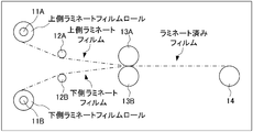
- FIG. 2 is a schematic diagram illustrating a configuration of a laminating mechanism in a vacuum chamber.
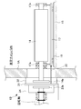
- FIG. 3 is a schematic diagram illustrating an example of an installation structure of a take-up roller.
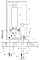
- FIG. 9 is a schematic diagram illustrating an example of an installation structure of a winding roller 14 according to a first modification.
- FIG. 1 is a schematic diagram showing the overall configuration of a vacuum laminator 1 according to the present invention.
- main parts are shown as a perspective view penetrating the inside of the vacuum laminator 1.
- FIG. 2 is a schematic diagram showing a configuration of a laminating mechanism in a vacuum chamber.
- the vacuum laminator 1 includes an upper film roll shaft 11A, a lower film roll shaft 11B, an upper tension roller 12A, a lower tension roller 12B, and an upper film roll shaft 11B.
- a laminating roller 13A, a lower laminating roller 13B, a winding roller 14, a centering plate 15, a separate plate 16, and a carriage 17 are provided.
- the vacuum laminator 1 includes torque adjusting motors 21 and 22 and a rotation driving motor 23 as actuators outside the vacuum chamber 1A.
- a plurality of through holes are formed in the partition wall of the vacuum chamber 1A for the purpose of connecting members and the like, and each of the through holes is provided with a seal portion 1B for preventing vacuum leakage in the through hole.
- the upper film roll shaft 11A constitutes a rotation shaft of a film roll for supplying an upper laminated film used for vacuum lamination, and the rotation torque is controlled by a torque adjusting motor 21.
- the lower film roll shaft 11B constitutes a rotation shaft of a film roll for supplying a lower laminate film used for vacuum lamination, and the rotation torque is controlled by a torque adjusting motor 22.
- the upper tension roller 12A is a tension roller installed to detect the tension of the upper laminate film.
- the upper tension roller 12A may be a guide roll that guides the conveyance of the upper laminate film.
- a dancer roller may be provided in place of the upper tension roller 12A, and the slack of the upper laminate film may be eliminated by a mechanical structure.
- the lower tension roller 12B is a tension roller installed to detect the tension of the lower laminate film.
- the lower tension roller 12B may be a guide roll that guides the conveyance of the lower laminate film.
- a dancer roller may be provided instead of the lower tension roller 12B, and the looseness of the lower laminate film may be eliminated by a mechanical structure.
- the upper laminating roller 13A and the lower laminating roller 13B are driven to rotate by the transport of the laminating film, and the upper laminating film and the lower laminating film sandwiched between the upper laminating roller 13A and the lower laminating roller 13B are evacuated. Lamination is performed by pressure bonding in an environment.
- the take-up roller 14 is supported by a support member 17a fixed to the carriage 17 so that the rotation shaft can rotate.
- the take-up roller 14 is rotatably driven by the rotation drive motor 23 to take up the laminated film carried out from the upper laminating roller 13A and the lower laminating roller 13B.
- the rotation drive motor 23 A specific example of the installation structure of the winding roller 14 will be described later.
- the centering plate 15 is a plate-like member fixed to a floor surface in the vacuum chamber 1A with bolts or the like.
- a separate plate 16 On the centering plate 15, a separate plate 16, a cart 17, and a winding roller 14 are installed.
- the separate plate 16 is a plate-like member whose four corners are supported by jack bolts with respect to the centering plate 15, and by adjusting the jack bolts, the inclination of the centering plate 15 and the vacuum chamber 1A with respect to the floor surface is adjusted. It is possible to do. Thereby, as the alignment adjustment, the posture of the winding roller 14 can be adjusted (the inclination of the rotating shaft can be adjusted).
- each bolt hole of the separate plate 16 is a long hole that is long in one direction (for example, a direction orthogonal to the thrust direction), and the entire separate plate 16 can be moved in parallel in this one direction. Has become.
- the carriage 17 is configured to be movable on the separate plate 16 in the thrust direction of the winding roller 14.
- the separate plate 16 and the carriage 17 can be connected, for example, via a linear guide so as to be linearly movable in the thrust direction.
- the carriage 17 is mechanically connected to the rotational drive motor 23 so that the movement in the thrust direction is interlocked, as schematically shown by a dashed line in FIG.
- the torque adjustment motor 21 includes a transmission torque adjustment mechanism (for example, a powder clutch) and generates a rotation torque for controlling the tension of the upper laminate film sent from the upper film roll shaft 11A.
- the torque adjustment motor 22 includes a transmission torque adjustment mechanism (for example, a powder clutch or the like) and generates a rotation torque for controlling the tension of the lower laminate film sent from the lower film roll shaft 11B.
- the rotation drive motor 23 includes a transmission torque adjustment mechanism (for example, a powder clutch or the like), and generates a rotation torque for driving the winding roller 14 to rotate.
- the torque adjusting motors 21 and 22 and the rotation driving motor 23 may not be provided with a transmission torque adjusting mechanism and may adjust the torque by controlling the output rotating torque.
- a mechanism for example, a powder brake or the like for adjusting the rotational resistance of the upper film roll shaft 11A and the lower film roll shaft 11B may be provided. Also in this case, the tension of the upper laminate film and the lower laminate film sent out from the upper film roll shaft 11A and the lower film roll shaft 11B can be controlled.
- FIG. 3 is a schematic diagram illustrating an example of an installation structure of the winding roller 14.
- the take-up roller 14 has an alignment adjustment function to which the present invention is applied.
- the take-up roller 14 is rotatably supported by a support member 17a fixed to a carriage 17 inside the vacuum chamber 1A so as to be rotatable.
- a disk 14a for magnet coupling is installed, and at the tip of the rotating shaft of the rotation driving motor 23, a disk 23a is placed across the boundary of the vacuum region. And are electromagnetically coupled.
- the rotating shaft of the take-up roller 14 passes through the partition wall of the vacuum chamber 1A, and the disk 14a provided at the tip of the rotary shaft of the take-up roller 14 has a sealing portion provided outside the partition wall.
- the disk 23a installed at the tip of the rotation shaft of the rotation drive motor 23 is opposed to the disk 23a with the sealing plate 31 of the seal portion 1B interposed therebetween.
- the member (here, the sealing plate 31) provided between the disk 14a and the disk 23a is desirably made of a material that does not generate eddy current or a material that hardly generates eddy current. It can be made of a resin that does not generate or a metal such as stainless steel that does not easily generate eddy current.
- the seal portion 1B has a structure in which the rotating shaft of the take-up roller 14 seals a through-hole passing through the vacuum chamber 1A. It is installed outside.
- the sealing plate 31 is connected to one end of the carriage 17 by a connecting member 33 via a free joint. Therefore, by changing the distance between the sealing plate 31 and the partition of the vacuum chamber 1A, the take-up roller 14 and the disk 14a move in the thrust direction.
- a separate motor for movement or manual operation can be provided as means for moving the take-up roller 14 and the disk 14a in the thrust direction.
- control of the edge position of the laminated film is realized as alignment adjustment.
- the distance and inclination between the disks 14a and 23a that are electromagnetically connected are not required to be strict.
- the shift is allowed within the set range.
- the coupling conditions for the electromagnetically coupled disks 14a and 23a to be appropriately electromagnetically coupled are as follows: the disk 14a of the take-up roller 14 is adjusted by the alignment adjustment so that the disk 14a of the rotary drive motor 23 is rotated.
- the maximum value of the amount of deviation occurring with respect to 23a is allowable. Therefore, according to the vacuum laminator 1 according to the present embodiment, the alignment adjustment of the winding roller 14 can be performed more easily.
- the rotation shaft of the rotation drive motor 23 is rotatably supported by restricting axial movement of the holding member 34 fixed to the sealing plate 31. Therefore, in the case of the structure example shown in FIG. 3, when the take-up roller 14 is moved in the thrust direction in order to adjust the edge position of the laminated film, the holding member 34, the disk 23a, the connecting member 33, the carriage 17, The positional relationship among the support member 17a, the take-up roller 14, and the disk 14a is maintained. That is, when the alignment adjustment in the thrust direction is performed, the positional relationship between the disk 14a provided at the tip of the rotation shaft of the take-up roller 14 and the disk 23a provided at the tip of the rotation shaft of the rotation driving motor 23 is determined.
- the vacuum laminator 1 When the alignment is maintained, the burden of performing the adjustment work of each part including the state of the electromagnetic connection is reduced. Further, according to the vacuum laminator 1 according to the present embodiment, a structure that does not generate resistance (rotational friction) to the rotating shaft in the seal portion 1B can be achieved.
- the edge position of the laminated film wound by the winding roller 14 is adjusted in conjunction with the adjustment of the inclination of the rotation axis of each roller.
- the holding member 34, the disk 23a, the connecting member 33, the carriage 17, the support member 17a, the take-up roller 14, and the disk 14a are taken up by the take-up roller.
- the edge position of the laminated film is adjusted.
- FIG. 4 is a schematic diagram illustrating an example of an installation structure of the winding roller 14 according to the present modification.
- the installation structure example shown in FIG. 4 mainly includes a thrust adjustment motor 24 for position adjustment in the thrust direction, is connected to the carriage 17, and has a reduction mechanism 141 installed on the rotation shaft of the take-up roller 14. This is different from the installation structure example shown in FIG.
- the rotating shaft of the thrust adjustment motor 24 passes through a through hole formed in the partition wall of the vacuum chamber 1A, and is connected to one end of the carriage 17 via a free joint.
- the seal part 1B is installed in the part of this through-hole.
- the output of the thrust adjustment motor 24 is smaller than the output of the rotary drive motor 23, the size of the seal portion 1B in FIG. 3 can be made smaller.
- the reduction mechanism 141 has a drive force input shaft 141a coupled to the disk 14a, a gear 141b having the drive force input shaft 141a as a rotation axis, and a rotation shaft of the take-up roller 14, and is provided with a gear 141b. And a matching gear 141c.
- the input shaft 141a and the gear 141b are rotatably supported by a support member 16a installed on the separate plate 16, and are configured not to move in the thrust direction.
- the take-up roller 14 is rotatably supported by a support member 17 a installed on the carriage 17, and moves in the thrust direction when the carriage 17 is moved by the thrust adjustment motor 24. At this time, the bogie 17 is moved in a range in which the engagement between the gear 141b and the gear 141c is maintained.
- the rotation driving motor 23 does not move in the thrust direction and does not require members arranged in the thrust direction such as the bellows 32 and the holding member 34 in the seal portion 1B, the vacuum chamber 1A The size of the protruding portion can be suppressed.
- this portion can be used for different functions.
- a rotary joint 14b is installed at the end of the rotation shaft of the winding roller 14, and the air for air chuck installed on the rotation shaft of the winding roller 14 via the rotary joint 14b. Supply routes.
- the strength of the air chuck can be adjusted in accordance with the change,
- the winding roller 14 can be more appropriately held on the rotating shaft. Further, also in the vacuum laminator 1 according to the first modification, it is possible to adopt a structure in which resistance (rotational friction) to the rotating shaft in the seal portion 1B is not generated.
- the present invention is applied to the take-up roller 14 as an example, but the present invention is not limited to this.
- the present invention can be applied to various rollers, such as the upper film roll shaft 11A or the lower film roll shaft 11B, which rotate when a driving force is input from outside the vacuum chamber 1A.
- the disk 14a is provided at the end of the rotation shaft of the winding roller 14, and the disk 23a is disposed at the end of the rotation shaft of the rotation driving motor 23 so as to face the disk 14a.
- the configuration in which the disk 14a and the disk 23a are electromagnetically connected has been described as an example, but the present invention is not limited to this. That is, as a form of electromagnetically connecting the rotation shaft of the take-up roller 14 and the rotation shaft of the rotation drive motor 23, it is possible to adopt various structures using a device other than a disk.
- one of the rotation shaft of the winding roller 14 and the rotation shaft of the rotation drive motor 23 is an inner cylinder
- the other is an outer cylinder
- magnets are installed on the outer periphery of the inner cylinder and the inner periphery of the outer cylinder, respectively. May be electromagnetically connected to each other.
- the present invention is not limited to the above-described embodiments. Further, the effects described in the present embodiment merely enumerate the most preferable effects resulting from the present invention, and the effects according to the present invention are not limited to those described in the present embodiment.
Landscapes
- Engineering & Computer Science (AREA)
- Mechanical Engineering (AREA)
- Manufacturing & Machinery (AREA)
- Lining Or Joining Of Plastics Or The Like (AREA)
Abstract
Le problème est de permettre de réaliser plus facilement un réglage d'alignement d'une machine à stratifier qui effectue une stratification sous vide. La solution selon l'invention porte sur une machine à stratifier qui comprend : une chambre à vide ; un rouleau qui est installé à l'intérieur de la chambre à vide et est utilisé pour la stratification sous vide ; un mécanisme de réglage d'alignement qui règle l'alignement du rouleau ; et un actionneur qui génère une force d'entraînement pour faire tourner le rouleau. L'extrémité de pointe d'un arbre de rotation côté sortie auquel est délivrée la force d'entraînement de l'actionneur est disposée à l'extérieur d'une zone de vide. L'extrémité de pointe d'un arbre de rotation côté entrée auquel est entrée la force d'entraînement pour faire tourner le rouleau est disposée à l'intérieur de la zone de vide. L'extrémité de pointe de l'arbre de rotation côté sortie et l'extrémité de pointe de l'arbre de rotation côté entrée sont accouplées électromagnétiquement l'une à l'autre.
Priority Applications (2)
| Application Number | Priority Date | Filing Date | Title |
|---|---|---|---|
| JP2020525440A JP7293218B2 (ja) | 2018-06-18 | 2019-05-31 | ラミネータ及びラミネータのアライメント調整方法 |
| CN201980040917.5A CN112313063B (zh) | 2018-06-18 | 2019-05-31 | 层压机及层压机的对准调整方法 |
Applications Claiming Priority (2)
| Application Number | Priority Date | Filing Date | Title |
|---|---|---|---|
| JP2018115654 | 2018-06-18 | ||
| JP2018-115654 | 2018-06-18 |
Publications (1)
| Publication Number | Publication Date |
|---|---|
| WO2019244602A1 true WO2019244602A1 (fr) | 2019-12-26 |
Family
ID=68983718
Family Applications (1)
| Application Number | Title | Priority Date | Filing Date |
|---|---|---|---|
| PCT/JP2019/021757 Ceased WO2019244602A1 (fr) | 2018-06-18 | 2019-05-31 | Machine à stratifier et procédé de réglage d'alignement de machine à stratifier |
Country Status (3)
| Country | Link |
|---|---|
| JP (1) | JP7293218B2 (fr) |
| CN (1) | CN112313063B (fr) |
| WO (1) | WO2019244602A1 (fr) |
Cited By (2)
| Publication number | Priority date | Publication date | Assignee | Title |
|---|---|---|---|---|
| WO2022065300A1 (fr) * | 2020-09-25 | 2022-03-31 | 日東電工株式会社 | Procédé de production de stratifié optique |
| TWI913321B (zh) | 2020-09-25 | 2026-02-01 | 日商日東電工股份有限公司 | 光學積層體之製造方法 |
Families Citing this family (1)
| Publication number | Priority date | Publication date | Assignee | Title |
|---|---|---|---|---|
| CN115535668B (zh) * | 2022-10-31 | 2025-07-15 | 怀化天马隆旭印务有限公司 | 一种印刷纸张输送装置 |
Citations (4)
| Publication number | Priority date | Publication date | Assignee | Title |
|---|---|---|---|---|
| JPS5266581A (en) * | 1975-12-01 | 1977-06-02 | Hitachi Chemical Co Ltd | Apparatus for continuous plying * sticking each other under vacuum |
| JPS58199152A (ja) * | 1982-05-06 | 1983-11-19 | ペ−タ−・レンツ | シ−トをプラスチツク・フイルムでラミネ−ト被覆する装置 |
| JPS63144035A (ja) * | 1986-12-05 | 1988-06-16 | Toyoda Gosei Co Ltd | 模様付形装置 |
| JPH04345843A (ja) * | 1991-05-23 | 1992-12-01 | Hitachi Chem Co Ltd | ロールラミネート装置 |
Family Cites Families (5)
| Publication number | Priority date | Publication date | Assignee | Title |
|---|---|---|---|---|
| JP2983253B2 (ja) * | 1990-06-04 | 1999-11-29 | 伯東株式会社 | 真空ラミネータ |
| US7011130B2 (en) * | 2003-10-17 | 2006-03-14 | Primera Technology, Inc. | Laminator for applying a protective layer to a disc |
| DE202006002982U1 (de) * | 2006-02-24 | 2006-05-18 | Tünkers Maschinenbau Gmbh | Kaschiermaschine |
| JP4814685B2 (ja) * | 2006-04-20 | 2011-11-16 | 有限会社レオテクノ | ラミネータ |
| JP6403159B2 (ja) * | 2015-02-26 | 2018-10-10 | 株式会社日立プラントメカニクス | フィルムの真空ラミネート装置 |
-
2019
- 2019-05-31 CN CN201980040917.5A patent/CN112313063B/zh active Active
- 2019-05-31 JP JP2020525440A patent/JP7293218B2/ja active Active
- 2019-05-31 WO PCT/JP2019/021757 patent/WO2019244602A1/fr not_active Ceased
Patent Citations (4)
| Publication number | Priority date | Publication date | Assignee | Title |
|---|---|---|---|---|
| JPS5266581A (en) * | 1975-12-01 | 1977-06-02 | Hitachi Chemical Co Ltd | Apparatus for continuous plying * sticking each other under vacuum |
| JPS58199152A (ja) * | 1982-05-06 | 1983-11-19 | ペ−タ−・レンツ | シ−トをプラスチツク・フイルムでラミネ−ト被覆する装置 |
| JPS63144035A (ja) * | 1986-12-05 | 1988-06-16 | Toyoda Gosei Co Ltd | 模様付形装置 |
| JPH04345843A (ja) * | 1991-05-23 | 1992-12-01 | Hitachi Chem Co Ltd | ロールラミネート装置 |
Cited By (3)
| Publication number | Priority date | Publication date | Assignee | Title |
|---|---|---|---|---|
| WO2022065300A1 (fr) * | 2020-09-25 | 2022-03-31 | 日東電工株式会社 | Procédé de production de stratifié optique |
| JP7621081B2 (ja) | 2020-09-25 | 2025-01-24 | 日東電工株式会社 | 光学積層体の製造方法 |
| TWI913321B (zh) | 2020-09-25 | 2026-02-01 | 日商日東電工股份有限公司 | 光學積層體之製造方法 |
Also Published As
| Publication number | Publication date |
|---|---|
| CN112313063B (zh) | 2022-10-21 |
| CN112313063A (zh) | 2021-02-02 |
| JP7293218B2 (ja) | 2023-06-19 |
| JPWO2019244602A1 (ja) | 2021-09-02 |
Similar Documents
| Publication | Publication Date | Title |
|---|---|---|
| EP3099954B1 (fr) | Appareil d'embrayage a fluide magnétorhéologique et systèmes de commande | |
| JP7293218B2 (ja) | ラミネータ及びラミネータのアライメント調整方法 | |
| US10746235B2 (en) | Multimode control system for magnetorheological fluid actuator unit | |
| JP2659998B2 (ja) | リニアアクチュエータ | |
| CN103580550A (zh) | 制动装置、驱动系统以及机器人 | |
| JP6580113B2 (ja) | スパッタ装置及びその制御方法 | |
| US20130047758A1 (en) | Z-axis stage driving apparatus, stage driving apparatus, and method for manipulating stage driving apparatus | |
| JP2019177437A (ja) | ロボットの手首ユニット | |
| KR20070116006A (ko) | 브레이크 제어를 위한 형상-변화 재료를 갖는 엘리베이터브레이크 액추에이터 | |
| JP2019060477A (ja) | 減速機およびそれを用いたアクチュエータ | |
| WO2018066652A1 (fr) | Embrayage de prévention d'entrée inverse et actionneur associé | |
| JP2019150914A (ja) | ロボットの手首ユニット | |
| KR20140129441A (ko) | 정밀위치 제어가 가능한 안테나 포지셔너 | |
| US20100188028A1 (en) | Drive device comprising a plurality of drives and regulating system for this overall drive | |
| JP3312747B2 (ja) | フェイルセイフ機構付き送りねじ装置 | |
| KR20230138200A (ko) | 자기력을 이용한 덴서 장치 | |
| JP6098187B2 (ja) | 回転機構および搬送装置 | |
| JP2001263444A (ja) | フリクションフリー・ドライブシステム | |
| US12084321B2 (en) | Stage hoist motor assembly | |
| EP4474668B1 (fr) | Ensemble embrayage/frein | |
| JP2010261549A (ja) | 制動装置、ステージ移動装置、ワーク処理装置及び制動方法 | |
| CN119028894A (zh) | 具有旋转纠偏功能的晶圆快速定位二维柔性铰链平台 | |
| JP2006288166A (ja) | 双方向の電磁駆動力を利用したアクチュエータ | |
| JP2017063522A (ja) | ローラ | |
| WO2024119264A1 (fr) | Actionneur haptique utilisant un appareil d'embrayage à fluide magnéto-rhéologique |
Legal Events
| Date | Code | Title | Description |
|---|---|---|---|
| 121 | Ep: the epo has been informed by wipo that ep was designated in this application |
Ref document number: 19821499 Country of ref document: EP Kind code of ref document: A1 |
|
| DPE1 | Request for preliminary examination filed after expiration of 19th month from priority date (pct application filed from 20040101) | ||
| ENP | Entry into the national phase |
Ref document number: 2020525440 Country of ref document: JP Kind code of ref document: A |
|
| NENP | Non-entry into the national phase |
Ref country code: DE |
|
| 122 | Ep: pct application non-entry in european phase |
Ref document number: 19821499 Country of ref document: EP Kind code of ref document: A1 |