WO2019244747A1 - 閉鎖弁 - Google Patents
閉鎖弁 Download PDFInfo
- Publication number
- WO2019244747A1 WO2019244747A1 PCT/JP2019/023316 JP2019023316W WO2019244747A1 WO 2019244747 A1 WO2019244747 A1 WO 2019244747A1 JP 2019023316 W JP2019023316 W JP 2019023316W WO 2019244747 A1 WO2019244747 A1 WO 2019244747A1
- Authority
- WO
- WIPO (PCT)
- Prior art keywords
- component
- valve
- refrigerant
- heat source
- closing
- Prior art date
- Legal status (The legal status is an assumption and is not a legal conclusion. Google has not performed a legal analysis and makes no representation as to the accuracy of the status listed.)
- Ceased
Links
Images







Classifications
-
- F—MECHANICAL ENGINEERING; LIGHTING; HEATING; WEAPONS; BLASTING
- F25—REFRIGERATION OR COOLING; COMBINED HEATING AND REFRIGERATION SYSTEMS; HEAT PUMP SYSTEMS; MANUFACTURE OR STORAGE OF ICE; LIQUEFACTION SOLIDIFICATION OF GASES
- F25B—REFRIGERATION MACHINES, PLANTS OR SYSTEMS; COMBINED HEATING AND REFRIGERATION SYSTEMS; HEAT PUMP SYSTEMS
- F25B13/00—Compression machines, plants or systems, with reversible cycle
-
- F—MECHANICAL ENGINEERING; LIGHTING; HEATING; WEAPONS; BLASTING
- F25—REFRIGERATION OR COOLING; COMBINED HEATING AND REFRIGERATION SYSTEMS; HEAT PUMP SYSTEMS; MANUFACTURE OR STORAGE OF ICE; LIQUEFACTION SOLIDIFICATION OF GASES
- F25B—REFRIGERATION MACHINES, PLANTS OR SYSTEMS; COMBINED HEATING AND REFRIGERATION SYSTEMS; HEAT PUMP SYSTEMS
- F25B41/00—Fluid-circulation arrangements
- F25B41/20—Disposition of valves, e.g. of on-off valves or flow control valves
- F25B41/24—Arrangement of shut-off valves for disconnecting a part of the refrigerant cycle, e.g. an outdoor part
-
- F—MECHANICAL ENGINEERING; LIGHTING; HEATING; WEAPONS; BLASTING
- F16—ENGINEERING ELEMENTS AND UNITS; GENERAL MEASURES FOR PRODUCING AND MAINTAINING EFFECTIVE FUNCTIONING OF MACHINES OR INSTALLATIONS; THERMAL INSULATION IN GENERAL
- F16K—VALVES; TAPS; COCKS; ACTUATING-FLOATS; DEVICES FOR VENTING OR AERATING
- F16K1/00—Lift valves or globe valves, i.e. cut-off apparatus with closure members having at least a component of their opening and closing motion perpendicular to the closing faces
- F16K1/02—Lift valves or globe valves, i.e. cut-off apparatus with closure members having at least a component of their opening and closing motion perpendicular to the closing faces with screw-spindle
- F16K1/04—Lift valves or globe valves, i.e. cut-off apparatus with closure members having at least a component of their opening and closing motion perpendicular to the closing faces with screw-spindle with a cut-off member rigid with the spindle, e.g. main valves
-
- F—MECHANICAL ENGINEERING; LIGHTING; HEATING; WEAPONS; BLASTING
- F16—ENGINEERING ELEMENTS AND UNITS; GENERAL MEASURES FOR PRODUCING AND MAINTAINING EFFECTIVE FUNCTIONING OF MACHINES OR INSTALLATIONS; THERMAL INSULATION IN GENERAL
- F16K—VALVES; TAPS; COCKS; ACTUATING-FLOATS; DEVICES FOR VENTING OR AERATING
- F16K11/00—Multiple-way valves, e.g. mixing valves; Pipe fittings incorporating such valves
- F16K11/02—Multiple-way valves, e.g. mixing valves; Pipe fittings incorporating such valves with all movable sealing faces moving as one unit
- F16K11/04—Multiple-way valves, e.g. mixing valves; Pipe fittings incorporating such valves with all movable sealing faces moving as one unit comprising only lift valves
-
- F—MECHANICAL ENGINEERING; LIGHTING; HEATING; WEAPONS; BLASTING
- F16—ENGINEERING ELEMENTS AND UNITS; GENERAL MEASURES FOR PRODUCING AND MAINTAINING EFFECTIVE FUNCTIONING OF MACHINES OR INSTALLATIONS; THERMAL INSULATION IN GENERAL
- F16K—VALVES; TAPS; COCKS; ACTUATING-FLOATS; DEVICES FOR VENTING OR AERATING
- F16K27/00—Construction of housing; Use of materials therefor
- F16K27/02—Construction of housing; Use of materials therefor of lift valves
- F16K27/0263—Construction of housing; Use of materials therefor of lift valves multiple way valves
-
- F—MECHANICAL ENGINEERING; LIGHTING; HEATING; WEAPONS; BLASTING
- F24—HEATING; RANGES; VENTILATING
- F24F—AIR-CONDITIONING; AIR-HUMIDIFICATION; VENTILATION; USE OF AIR CURRENTS FOR SCREENING
- F24F1/00—Room units for air-conditioning, e.g. separate or self-contained units or units receiving primary air from a central station
- F24F1/0003—Room units for air-conditioning, e.g. separate or self-contained units or units receiving primary air from a central station characterised by a split arrangement, wherein parts of the air-conditioning system, e.g. evaporator and condenser, are in separately located units
-
- F—MECHANICAL ENGINEERING; LIGHTING; HEATING; WEAPONS; BLASTING
- F24—HEATING; RANGES; VENTILATING
- F24F—AIR-CONDITIONING; AIR-HUMIDIFICATION; VENTILATION; USE OF AIR CURRENTS FOR SCREENING
- F24F1/00—Room units for air-conditioning, e.g. separate or self-contained units or units receiving primary air from a central station
- F24F1/06—Separate outdoor units, e.g. outdoor unit to be linked to a separate room comprising a compressor and a heat exchanger
- F24F1/26—Refrigerant piping
- F24F1/32—Refrigerant piping for connecting the separate outdoor units to indoor units
-
- F—MECHANICAL ENGINEERING; LIGHTING; HEATING; WEAPONS; BLASTING
- F24—HEATING; RANGES; VENTILATING
- F24F—AIR-CONDITIONING; AIR-HUMIDIFICATION; VENTILATION; USE OF AIR CURRENTS FOR SCREENING
- F24F5/00—Air-conditioning systems or apparatus not covered by F24F1/00 or F24F3/00, e.g. using solar heat or combined with household units such as an oven or water heater
- F24F5/0007—Air-conditioning systems or apparatus not covered by F24F1/00 or F24F3/00, e.g. using solar heat or combined with household units such as an oven or water heater cooling apparatus specially adapted for use in air-conditioning
- F24F5/001—Compression cycle type
-
- F—MECHANICAL ENGINEERING; LIGHTING; HEATING; WEAPONS; BLASTING
- F25—REFRIGERATION OR COOLING; COMBINED HEATING AND REFRIGERATION SYSTEMS; HEAT PUMP SYSTEMS; MANUFACTURE OR STORAGE OF ICE; LIQUEFACTION SOLIDIFICATION OF GASES
- F25B—REFRIGERATION MACHINES, PLANTS OR SYSTEMS; COMBINED HEATING AND REFRIGERATION SYSTEMS; HEAT PUMP SYSTEMS
- F25B41/00—Fluid-circulation arrangements
- F25B41/20—Disposition of valves, e.g. of on-off valves or flow control valves
-
- F—MECHANICAL ENGINEERING; LIGHTING; HEATING; WEAPONS; BLASTING
- F25—REFRIGERATION OR COOLING; COMBINED HEATING AND REFRIGERATION SYSTEMS; HEAT PUMP SYSTEMS; MANUFACTURE OR STORAGE OF ICE; LIQUEFACTION SOLIDIFICATION OF GASES
- F25B—REFRIGERATION MACHINES, PLANTS OR SYSTEMS; COMBINED HEATING AND REFRIGERATION SYSTEMS; HEAT PUMP SYSTEMS
- F25B41/00—Fluid-circulation arrangements
- F25B41/40—Fluid line arrangements
-
- F—MECHANICAL ENGINEERING; LIGHTING; HEATING; WEAPONS; BLASTING
- F16—ENGINEERING ELEMENTS AND UNITS; GENERAL MEASURES FOR PRODUCING AND MAINTAINING EFFECTIVE FUNCTIONING OF MACHINES OR INSTALLATIONS; THERMAL INSULATION IN GENERAL
- F16L—PIPES; JOINTS OR FITTINGS FOR PIPES; SUPPORTS FOR PIPES, CABLES OR PROTECTIVE TUBING; MEANS FOR THERMAL INSULATION IN GENERAL
- F16L13/00—Non-disconnectable pipe joints, e.g. soldered, adhesive, or caulked joints
- F16L13/08—Soldered joints
-
- F—MECHANICAL ENGINEERING; LIGHTING; HEATING; WEAPONS; BLASTING
- F25—REFRIGERATION OR COOLING; COMBINED HEATING AND REFRIGERATION SYSTEMS; HEAT PUMP SYSTEMS; MANUFACTURE OR STORAGE OF ICE; LIQUEFACTION SOLIDIFICATION OF GASES
- F25B—REFRIGERATION MACHINES, PLANTS OR SYSTEMS; COMBINED HEATING AND REFRIGERATION SYSTEMS; HEAT PUMP SYSTEMS
- F25B2345/00—Details for charging or discharging refrigerants; Service stations therefor
- F25B2345/001—Charging refrigerant to a cycle
Definitions
- Some conventional heat source units have a refrigerant flowing inside the unit. By giving heat energy to the refrigerant with the heat source unit or removing heat energy from the refrigerant with the heat source unit, the heat source unit can supply the heated or cooled refrigerant to the utilization unit.
- a heat source unit is usually provided with a closing valve as described in, for example, Patent Document 1 (Japanese Patent Application Laid-Open No. 2013-242038).
- a valve body for opening and closing the closing valve to control opening and shutting of the flow of the refrigerant is arranged. This valve element moves to open or close the flow path inside the closing valve, thereby opening and closing the closing valve.
- the shutoff valve described in Patent Document 1 is connected to the refrigerant pipe of the heat source unit, and is also connected to the refrigerant pipe extending to the use unit. Further, the shut-off valve of Patent Document 1 is fixed to a heat source unit such as an outdoor unit. For the connection with the refrigerant pipe and the fixing to the heat source unit, the closing valve is required to have high accuracy and high strength. In order to satisfy such a demand, copper or a copper alloy is used for the shut-off valve described in Patent Document 1. Further, it is described that a part of the closing valve is formed of aluminum, an aluminum alloy, or a synthetic resin instead of copper or a copper alloy.
- an aluminum alloy or a synthetic resin is advantageous for weight reduction, but causes a decrease in strength and is likely to cause deformation due to long-term use. When the closing valve is deformed, the risk of refrigerant leaking from the closing valve increases.
- the closing valve allows the refrigerant to flow between the first refrigerant pipe and the second refrigerant pipe while being connected between the first refrigerant pipe extending to the use unit and the second refrigerant pipe of the heat source unit.
- a closing valve having a flow passage therein and switching the opening and closing of the flow passage, wherein the closing valve can move through a movement passage between a first position for closing the flow passage and a second position for opening the flow passage.
- a first component including a first connection portion connected to the first refrigerant pipe, and a second component including a valve housing portion for housing the valve body located at the second position
- the first component and the second component are separate components, and the strength of the second material forming the second component is greater than the strength of the first material forming the first component.
- the second component is connected to the second component. Since the second component is made of a material, the strength of the second component is increased as compared with the case where the second component is made of the first material, and the second component including the valve body accommodating portion through which the moving passage passes is hardly deformed. Can be provided.
- the shutoff valve of the second aspect is the shutoff valve of the first aspect, wherein the first material includes copper and the second material includes iron.
- the first component including the first connection portion connected to the first refrigerant pipe is configured. Since the first material contains copper, the strength of the second component can be easily made larger than the strength of the first component and the first connection portion can be easily processed, and the valve body housing portion and the first connection portion can be easily processed. , It is possible to provide an inexpensive shut-off valve from which refrigerant hardly leaks.
- the shutoff valve according to the third aspect is the shutoff valve according to the first aspect or the second aspect, wherein the first component and the second component are brazed to each other.
- the first component and the second component are brazed to each other, so that the first component and the second component can be firmly connected to each other.
- the closing valve according to a fourth aspect is the closing valve according to any one of the first aspect to the third aspect, wherein the first connection portion is connected to the first refrigerant pipe that has been subjected to the flare processing. .
- the first connecting portion connected to the first refrigerant pipe subjected to the flare processing is made of a first material having a lower strength than the second material forming the second component. From a good point, the range of selection of the first material is widened, and a material having high processing accuracy can be easily selected as the first material, and the first connection portion that can be connected to the flared first refrigerant pipe without any gap is provided. The dimensional accuracy can be easily realized.
- the closing valve according to a fifth aspect is the closing valve according to any one of the first aspect to the fourth aspect, and further includes a second connection portion connected to the second refrigerant pipe, and a support portion fixed to the heat source unit.
- the strength of the third material forming the second connecting portion and the supporting portion is configured to be greater than the strength of the first material.
- the strength of the third material forming the support portion is higher than the strength of the first material, it is easy to give the support portion high strength, and the first refrigerant pipe is connected to the first connection portion.
- the support is hardly deformed by the stress applied to the support, and the risk of refrigerant leakage from the second connection and the valve housing due to the deformation starting from the support is easily suppressed. Can be.
- a shut-off valve according to a sixth aspect is the shut-off valve according to the fifth aspect, wherein the support portion is included in the second part.
- the support portion is included in the second component and the portion from the valve body housing portion to the support portion is one component, the strength from the valve body housing portion to the support portion is easily increased. .
- a shut-off valve according to a seventh aspect is the shut-off valve according to the fifth aspect, wherein the shut-off valve includes a third component including a support portion, and the third component and the second component are separate components.
- the third component including the support portion is a separate component from the second component, for example, even when the support portion has a complicated shape, the influence of the shape of the support portion is reduced. Processing can be performed without giving two parts, and it is easy to obtain a valve body accommodating portion with high dimensional accuracy.
- the shut-off valve according to an eighth aspect is the shut-off valve according to any one of the first to seventh aspects, wherein the second component includes a service port for charging the heat source unit with the refrigerant.
- the service port since the service port is included in the second part, the service port can also be formed of the second material. Therefore, the strength of the service port is increased to reduce the risk of refrigerant leakage from the service port. Can be.
- the shut-off valve according to the ninth aspect is the shut-off valve according to any one of the first to seventh aspects, wherein the first component includes a service port for charging the heat source unit with the refrigerant.
- the service port since the service port is included in the first part, the service port can also be formed of the first material. Therefore, the processing accuracy of the service port is increased, and the risk of refrigerant leakage from the service port is reduced. be able to.
- FIG. 2 is a circuit diagram showing an example of an air conditioner using the closing valve according to the embodiment.
- FIG. 2 is an exemplary perspective view showing an example of the appearance of the air-conditioning apparatus of FIG. 1.
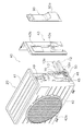
- FIG. 2 is an exploded perspective view showing a heat source unit of the air conditioner.
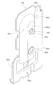
- FIG. 4 is a perspective view of a closing valve mounting plate that is a part of a casing of the heat source unit. Sectional drawing of a shutoff valve.
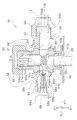
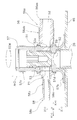
- FIG. 2 is a perspective view showing the appearance of the valve body. Sectional drawing of the valve main body for demonstrating the position of the valve body when a closing valve closes. Sectional drawing of the valve main body for demonstrating the position of the valve body when a closing valve opens. Sectional drawing of a shutoff valve.
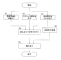
- FIG. 5 is a flowchart showing an example of a production flow of a closing valve. Sectional drawing of the stop valve which concerns on modification 1A. Sectional drawing of the stop valve which concerns on modification 1B. Sectional drawing of the stop valve which concerns on modification 1C. Sectional drawing of the stop valve concerning the modification 1E. Sectional drawing of the stop valve concerning the modification 1F.
- the air conditioner 10 includes a refrigerant circuit 11 configured by connecting a use unit 30 and a heat source unit 20 by refrigerant pipes 12 and 13.
- the refrigerant circuit 11 includes a compressor 21 provided in the heat source unit 20, a four-way valve 22, a heat source side heat exchanger 23, an expansion valve 24, accumulators 25, shutoff valves 50 and 70, and a utilization unit 30.
- the side heat exchanger 31 is connected.
- the air conditioner 10 has a configuration in which a cooling operation and a heating operation can be selectively performed by a vapor compression refrigeration cycle performed in the refrigerant circuit 11.
- the four-way valve 22 is in the connection state shown by the solid line in the cooling operation mode, and is in the connection state shown by the broken line in the heating operation mode.
- the refrigerant pipe 26 extending toward the inside of the heat source unit 20 is connected to the closing valve 50. 1 extends to the four-way valve 22.
- the refrigerant pipe 27 extending toward the inside of the heat source unit 20 is connected to the closing valve 70.
- the refrigerant pipe 27 shown in FIG. 1 extends to the expansion valve 24.
- FIG. 2 shows an example of the appearance of the air conditioner 10.
- the usage unit 30 is mounted on a wall surface or the like in a room, and the heat source unit 20 is installed outside the room.
- the piping member 14 connects the heat source unit 20 and the utilization unit 30.
- Refrigerant pipes 12 and 13 pass through the pipe member 14.
- electric wires and signal wires (not shown) connected to the heat source unit 20 and the utilization unit 30 pass through the pipe member 14.
- a heat insulating member that covers the outside of the refrigerant pipes 12 and 13, a decorative pipe cover, and the like are also included in the pipe member 14.
- the closing valves 50 and 70 are open.
- the refrigerant is confined in, for example, the heat source unit 20 and transported.
- the closing valves 50 and 70 are closed.
- the refrigerant pipes 12 and 13 are connected to the heat source unit 20, and the refrigerant pipes 12 and 13 are also connected to the use unit 30.
- the closing valves 50 and 70 are opened.
- the closing valves 50 and 70 may be opened and closed during maintenance of the air conditioner 10.
- the gas refrigerant or the gas-liquid two-phase refrigerant that has completed heat exchange in the use-side heat exchanger 31 is drawn into the compressor 21 through the refrigerant pipe 12, the closing valve 50, the four-way valve 22, and the accumulator 25.
- the conditioned air deprived of heat by the use-side heat exchanger 31 is blown out of the use unit 30 into, for example, a room, thereby cooling the room.
- the low-temperature and low-pressure refrigerant expanded and decompressed by the expansion valve 24 is sent to the heat source side heat exchanger 23, and performs heat exchange in the heat source side heat exchanger 23 to obtain heat from air.
- the gas refrigerant or the refrigerant in the gas-liquid two-phase state after the heat exchange in the heat source side heat exchanger 23 is sucked into the compressor 21 through the four-way valve 22 and the accumulator 25.
- the conditioned air heated by the use-side heat exchanger 31 is blown out from the use unit 30 into, for example, a room, thereby heating the room.
- the heat source unit 20 includes the heat source side fan 28, and the use unit 30 includes the use side fan 32.
- the heat source side fan 28 supplies air to the heat source side heat exchanger 23 in the cooling operation mode and the heating operation mode in order to promote heat exchange between the air and the refrigerant in the heat source side heat exchanger 23.
- the use-side fan 32 supplies air to the use-side heat exchanger 31 in the cooling operation mode and the heating operation mode in order to promote heat exchange between the air and the refrigerant in the use-side heat exchanger 31.
- FIG. 3 shows a state in which some parts of the heat source unit 20 have been removed and the heat source unit 20 has been disassembled.
- the parts removed in FIG. 3 are the right side plate 43 and the closing valve cover 90.
- the right side plate 43 is a part of the casing 40.
- the casing 40 is a hollow box and has six surfaces like a rectangular parallelepiped. That is, each member constituting the casing 40 is arranged on any of the top surface, the front surface, the right side surface, the left side surface, the rear surface, and the bottom surface.
- a top plate 41 is disposed on the top surface of the casing 40
- a front plate 42 is disposed on the front surface
- a right plate 43 is disposed so as to extend from the right side to a part of the rear surface
- a left side plate shown in FIG.
- a wire mesh or a suction grill (not shown) is arranged on the rear surface except for the right side plate 43
- a bottom plate 45 is arranged on the bottom surface.
- the top plate 41, the front plate 42, the right side plate 43, the left side plate, and the bottom plate 45 are preferably made of metal members to enhance safety, and are made of, for example, sheet metal.
- the compressor 21, the four-way valve 22, the heat source side heat exchanger 23, the expansion valve 24, and the heat source side fan 28 which have already been described are housed.
- the front plate 42 has an opening (not shown) through which air is blown out.
- This opening is, for example, circular, and a blowing grill 42a is arranged in front of the opening. The air entering from the rear surface of the casing 40 and passing through the heat source side heat exchanger 23 is blown toward the front of the heat source unit 20 through the blow grill 42a.
- a closing valve mounting plate 46 to which the closing valves 50 and 70 are fixed is attached to the bottom plate 45 by, for example, screws.
- the closing valve mounting plate 46 is preferably made of a metal member in order to enhance safety, and is made of, for example, a sheet metal.
- the closing valve mounting plate 46 is disposed on the right side surface. More specifically, the closing valve mounting plate 46 is mounted such that the closing valves 50 and 70 are located in the openings 43a of the right side plate 43.
- the right side surface of the casing 40 is constituted by the right side plate 43 and the closing valve mounting plate 46. That is, the closing valve attachment plate 46 constitutes a part of the casing 40.
- another opening 43b is formed on the opening 43a of the right side plate 43.
- An opening 43b is formed where the terminal board 49 disposed inside the casing 40 can be seen.
- Closure valve cover 90 is a cover that covers the closing valves 50 and 70.
- the closing valve cover 90 is attached to the right side plate 43.
- the closing valve cover 90 is configured to cover the openings 43a and 43b while being attached to the right side plate 43. Since the closing valves 50 and 70 protrude from the opening 43a of the casing 40, the bulging portion 90a of the closing valve cover 90 that bulges outward so as not to contact the closing valves 50 and 70. It is located near.
- An opening (not shown) is provided between the closing valve cover 90 and the right side plate 43 for drawing out the refrigerant pipes 12, 13 connected to the closing valves 50, 70.
- heat insulating cylinders 12a and 13a are attached to the outer circumference of the refrigerant pipes 12 and 13 shown in FIG. 3, respectively.
- FIG. 4 shows the appearance of the closing valve mounting plate 46 when the closing valve mounting plate 46 is viewed obliquely from the upper front right side.
- the closing valve mounting plate 46 has a flat portion 46a, a bulging portion 46b, a concave portion 46c, and a rib 46d.
- the flat portion 46a is a flat portion along the vertical plane of the right side plate 43 when the closing valve mounting plate 46 is mounted on the casing 40. Since at least a part of the flat portion 46a overlaps the right side plate 43, the opening 43a of the right side plate 43 can be closed by the closing valve mounting plate 46 without generating an unnecessary gap.
- the bulging portion 46b is a portion bulging toward the outside of the casing 40 from the flat portion 46a.
- the top 46ba of the bulging portion 46b is flat.
- Two mounting openings 46e, 46f to which the closing valves 50, 70 are mounted are formed in the flat top 46ba.
- the concave portion 46c is a portion that is concave toward the inside of the casing 40 than the flat portion 46a. Since the concave portion 46c is formed and the unevenness is formed on the closing valve mounting plate 46, the bending strength of the closing valve mounting plate 46 is improved.
- the rib 46d is formed by bending an end of the flat portion 46a toward the inside of the casing 40.
- the bending strength of the closing valve mounting plate 46 is improved.
- a screw (not shown) inserted into the screw hole 46g is also inserted into a screw hole (not shown) of the bottom plate 45, and the closing valve mounting plate 46 is fastened to the bottom plate 45 with a screw.
- the closing valve mounting plate 46 is preferably made of metal in order to improve safety.
- the closing valve mounting plate 46 is made of, for example, a sheet metal member. When the sheet metal member is pressed, for example, the closing valve mounting plate 46 having a complicated shape as described above is formed.
- the mounting openings 46e and 46f of the closing valve mounting plate 46 are surrounded by ribs 46h and 46i rising from the flat portion 46a. These ribs 46h and 46i can also be formed together when the shape of the closing valve mounting plate 46 is formed from a sheet metal member by press working, for example.
- Refrigerant pipes 26 and 27 are fixed inside the ribs 46h and 46i, for example, by brazing. Therefore, the brazing material is clad inside the ribs 46h and 46i.
- valve bodies 55 and 75 which will be described later, are fixed to the planar top portion 46ba around the ribs 46h and 46i, for example, by brazing.
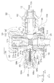
- FIG. 5 shows a cross-sectional shape of the closing valve 50.
- FIG. 6 shows the appearance of the closing valve 50.
- 7 and 8 are drawings for explaining the movement of the valve element 51 in the closing valve 50.
- the positive direction (Z (+)) of the Z axis of the coordinate axes shown in FIGS. 5 to 8 is the direction from the inside to the outside of the heat source unit 20, and the negative direction (Z (-)) is the heat source unit. 20 from the outside to the inside.
- the Z axis is an axis perpendicular to the right side.
- the + direction of the X axis is the direction from the shut-off valve 50 toward the refrigerant pipe 12, and here, the direction from the front to the rear of the heat source unit 20.
- the + direction of the Y axis is the direction from the bottom of the heat source unit 20 to the top.
- the shut-off valve 50 has a flow path 52 inside which the refrigerant flows between the refrigerant pipe 12 and the refrigerant pipe 26 while being connected between the refrigerant pipe 12 extending to the utilization unit 30 and the refrigerant pipe 26 of the heat source unit 20. Have.
- the closing valve 50 switches the opening and closing of the flow path 52 by the movement of the valve element 51.
- the valve element 51 can move through a movement passage 53 between a first position P1 (see FIG. 7) for closing the flow path 52 and a second position P2 (see FIG. 8) for opening the flow path 52. It is configured as follows.
- the moving passage 53 is threaded, and a part of the valve body 51 is threaded with an external thread 51a (see FIG. 8).
- the valve element 51 is rotated clockwise CW, the valve element 51 advances in the direction from the second position P2 toward the first position P1 (the direction of the arrow Ar1).
- the valve element 51 is rotated counterclockwise CCW, It proceeds in the direction from the first position P1 to the second position P2 (the direction of arrow Ar2).
- the flow path 52 is formed inside the valve body 55.
- the valve body 55 includes a first component 56, a second component 57, and a service port component 58.
- the first component 56, the second component 57, and the service port component 58 are separate components from each other.
- the joining surface BS1 of the first component 56 and the second component 57 is brazed, and the first component 56 and the second component 57 are integrated.
- the joining surface BS2 between the second component 57 and the service port component 58 is brazed, and the second component 57 and the service port component 58 are integrated.
- the outer periphery of the first component 56 at a position where it is fitted into the second component 57 and is in contact with the second component 57 is a hexagon.
- the outer periphery of the service port component 58 that is fitted into the second component 57 and in contact with the second component 57 has a hexagonal shape.
- the first component 56 includes a first connection portion 56a connected to the refrigerant pipe 12 extending to the use unit 30.
- the distal end portion 12b of the refrigerant pipe 12 is subjected to flare processing. For this reason, the inner diameter of the distal end portion 12b of the refrigerant pipe 12 increases as it approaches the distal end.
- a taper 56aa is provided at the tip of the first connection portion 56a of the first component 56 so as to match the shape of the tip 12b of the refrigerant pipe 12.
- the refrigerant pipe 12 is fastened to the first connection portion 56a by a flare nut 60. Therefore, a male screw 56ab coupled to the flare nut 60 is provided in a part of the first connection portion 56a.
- the first connection portion 56a is preferably processed with high dimensional accuracy.
- the first component 56 is made of a metal containing copper (Cu) in order to easily process the first connection portion 56a with high dimensional accuracy.
- the metal containing copper as the material of the first component 56 include brass.
- the brass that is the material of the first component 56 include C3604 (free-cutting brass) and C3771 (forging brass) specified in JIS H3250.
- the first component 56 can be easily formed by cutting a hexagonal prism-shaped brass member, for example.
- a through hole is drilled at the center of the hexagonal prism-shaped brass member with a drill or the like to form the channel 52.
- the cross-sectional shape of the flow path 52 is circular.
- the joining surface BS1 is formed by cutting with a lathe or the like at the end opposite to the end where the taper 56aa (see FIG. 6) is formed.
- the shape of the surface of the first component 56 is formed by cutting, for example, by cutting the male screw 56ab and the taper 56aa from the surface of the brass member with a lathe, the first component 56 made of brass can be obtained. .
- the reason why the hexagonal portion is left on the first component 56 is that the hexagonal location is used as a detent when the refrigerant pipe 12 is attached to the first component 56 with the flare nut 60.
- the second component 57 includes a valve body housing portion 57a that houses the valve body 51 located at the second position P2.
- the valve body housing portion 57a is a portion from the boundary between the movement passage 53 and the outer portion 52a of the flow path 52 to one end 53a of the movement passage 53 in the first component 56.
- the outer portion 52a of the flow path 52 is an inner peripheral wall of the flow path 52 that is far from the heat source unit 20 in the X-axis direction.
- the direction away from the heat source unit 20 is the + direction of the Z axis.
- the valve body 51 moves to the second position P2, and almost all of the valve body 51 is housed in the valve body housing portion 57a, so that the flow path 52 is opened.
- the refrigerant can flow between the refrigerant pipe 12 and the refrigerant pipe 26.
- the valve element 51 is moving to the second position P2
- the space between the inner peripheral surface of the moving passage 53 and the valve element 51 is sealed by the O-ring 51e of the valve element 51.
- the gas passes through the opening at one end 53a of the movement passage 53 from the gap between the inner peripheral surface of the movement passage 53 and the valve body 51. Leakage of refrigerant is prevented.
- valve lid 65 is attached to the second component 57, and the moving passage 53 is closed.
- a male screw 57 c coupled to a female screw 65 a cut inside the valve lid 65 is cut in a part of the outer peripheral surface of the second component 57.
- the valve lid 65 is screwed to the second component 57 to protect the valve body 51.
- the female passage 53c (see FIG. 8) is formed in the moving passage 53 in the valve body accommodating portion 57a at a portion near the outer portion 52a of the flow passage 52.
- the external thread 51a cut in the valve element 51 corresponds to the internal thread 53c in the valve element accommodating portion 57a.
- a hole 51b having a hexagonal cross section is provided in an upper portion of the valve element 51.
- the tapered portion 51d at the tip of the valve element 51 contacts the flow path 52 at the other end 53b of the moving path 53 without any gap.
- the inside diameter of the flow path 52 is small at the other end 53b of the moving passage 53 so that the tapered portion 51d can contact the flow path 52 at the other end 53b of the moving passage 53 without any gap.
- the portion where the inner diameter of the flow path 52 is small is the valve seat 59 on which the valve element 51 is seated.
- the valve seat 59 has a ring shape, and the center of the ring substantially coincides with the central axis of the moving passage 53.
- substantially matching means matching within a range of manufacturing error.
- the center axis of the movement path 53 having a circular cross section should coincide with the center axis of the flow path 52 having a circular cross section. Is preferred. If the center axis of the movement passage 53 is displaced from the center axis of the flow path 52 along the Z axis, a portion where the tapered portion 51d does not come into contact with the valve seat 59 is formed, and the blocking of the refrigerant becomes insufficient.
- the second component 57 includes the support portion 57b.
- the support portion 57b is a portion fixed to the heat source unit 20.
- the portion fixed to the closing valve mounting plate 46 is the support portion 57b.
- the second component 57 includes a fitting portion 57d.
- the rib 46h of the closing valve mounting plate 46 is fitted into the fitting portion 57d.
- the support portion 57b is configured by a rib or a tapered portion.
- the support portion 57b is brazed to the closing valve mounting plate 46.
- the brazing of the support portion 57b and the closing valve mounting plate 46 is performed by brazing the joining surface BS1 of the first component 56 and the second component 57 and brazing the joining surface BS2 of the service port component 58 and the second component 57. It is preferable to perform them together in a furnace at once from the viewpoint of reducing the number of manufacturing steps.
- the O-ring 51e is attached to the valve body 51, so that the support portion 57b and the closing valve attachment plate 46 are brazed, the joining surface BS1 between the first component 56 and the second component 57 is brazed, and a service port is used.
- the valve body 51 is attached to the valve body 55.
- the brazing of the support portion 57b and the closing valve mounting plate 46, the brazing of the joint surface BS1 of the first component 56 and the second component 57, and the brazing of the joint surface BS2 of the service port component 58 and the second component 57 are performed.
- the attachment may be performed separately.
- the first component 56 has a refrigerant.
- the second component 57 is manufactured using a metal containing copper (Cu), for example, brass, the strength cannot be achieved unless the thickness of the second component 57 is increased. Therefore, when the second component 57 is manufactured using brass, the second component 57 tends to be heavy, and the price tends to be high because a large amount of material is used.
- Cu metal containing copper
- the second component 57 is made of a metal containing iron (Fe), which can easily obtain higher strength than a metal containing copper.
- the metal containing iron include stainless steel. Since the heat source unit 20 is often installed outdoors, it is preferable to use stainless steel which does not easily rust. Therefore, the strength of the second material forming the second component 57 is higher than the strength of the first material forming the first component 56. The strength of these materials is compared by a tensile test (No. 11 test piece due to cylindrical shape) based on JIS standard Z2241 (2011).
- the second component 57 can be easily formed by processing a cylindrical stainless member, for example.
- the end of the cylindrical stainless member is widened by forging to form the support portion 57b.
- a convex portion for forming the joint surfaces BS1 and BS2 is formed at the center of the cylindrical stainless member by, for example, bulging.
- the joining surfaces BS1 and BS2 are formed on the convex portions of the cylindrical stainless member by, for example, cutting.
- a cutting process may be performed on the support portion 57b after forging.
- the second component 57 can be obtained by cutting the male screw 57c and the female screw 53c on the outer peripheral surface of the cylindrical stainless member.
- the service port component 58 is a component for providing a service port for filling the heat source unit 20 with the refrigerant.
- the service port component 58 includes a suction passage 58a extending along the X-axis (extending in the front-rear direction of the heat source unit 20). This suction path 58a is connected to the flow path 52.
- a valve core 69 is attached so as to close the suction path 58a.
- the valve core 69 has a built-in pin 69a for opening and closing. When the pin 69a is pushed in the + direction of the X axis, the pin 69a moves toward the flow path 52, and a flow passage is opened in the valve core 69.
- the cap 68 In a normal use state of the heat source unit 20 in which the service port is not used, the cap 68 is attached to the service port component 58, and the suction passage 58a is closed. A male screw 58b coupled to a female screw 68b cut inside the cap 68 is cut in a part of the outer peripheral surface of the service port component 58.
- the cap 68 is metal-touched and sealed to the service port component 58 at a location indicated by reference numeral 68a. That is, the cap 68 is in contact with the taper 58c of the service port component 58 without a gap.
- the service port component 58 is preferably processed with high dimensional accuracy.
- the service port component 58 is made of a metal containing copper (Cu) so that the service port component 58 can be easily processed with high dimensional accuracy.
- the metal containing copper which is a material of the service port component 58 include brass.
- Brass as a material of the service port component 58 includes, for example, C3604 or C3771 specified in JIS H3250.
- the service port component 58 can be easily formed by cutting a hexagonal prism-shaped brass member, for example.
- a suction hole 58a is formed by drilling a through hole at the center of the hexagonal prism-shaped brass member. Therefore, the cross-sectional shape of the suction passage 58a is circular.
- the joining surface BS2 is formed by cutting with a lathe or the like at the end opposite to the end where the taper 58c is formed. Then, if the shape of the surface of the service port part 58 is formed by cutting the male screw 58b and the taper 58c from the surface of the brass member with a lathe or the like, the service port part 58 made of brass is obtained. Can be.
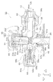
- the closing valve 70 has a valve body 75 formed of a plurality of brazed parts, similarly to the closing valve 50.
- the shut-off valve 70 differs from the shut-off valve 50 in that it does not have a service port and does not have a component corresponding to the service port component 58.
- the closing valve 70 has a configuration corresponding to the closing valve 50. Therefore, here, the correspondence between the components of the closing valve 70 and the components of the closing valve 50 will be described, and a part of the description of the closing valve 70 will be omitted.
- the closing valve 70 includes a valve body 51, an O-ring 51e, a flow path 52, a moving passage 53, a valve body 55, a first component 56, a first connecting portion 56a, a second component 57, and a valve housing 57a of the closing valve 50.
- the shut-off valve 70 has a flow path 72 inside which the refrigerant flows between the refrigerant pipe 13 and the refrigerant pipe 27 while being connected between the refrigerant pipe 13 extending to the utilization unit 30 and the refrigerant pipe 27 of the heat source unit 20. Have.
- the closing valve 70 also switches the opening and closing of the flow path 72 by the movement of the valve body 71.
- the valve body 71 is configured to be able to move through the moving passage 73 between a first position P1 for closing the flow path 72 and a second position P2 for opening the flow path 72.
- the moving passage 73 and a part of the valve body 71 are threaded, and when the valve body 71 is rotated clockwise, the valve body 71 moves in the direction from the second position P2 toward the first position P1. When rotated clockwise, it advances in the direction from the first position P1 to the second position P2.
- the flow path 72 is formed inside the valve body 75.
- the valve body 75 includes a first component 76 and a second component 77.
- the first component 76 and the second component 77 are separate components from each other. Then, the joining surface BS1 of the first component 76 and the second component 77 is brazed, and the first component 76 and the second component 77 are integrated.
- the first component 76 includes a first connection portion 76a connected to the refrigerant pipe 13 extending to the use unit 30.
- the distal end portion 13b of the refrigerant pipe 13 is flared.
- a taper 76aa is provided at the tip of the first connection portion 76a of the first component 76 so as to match the shape of the tip 13b of the refrigerant pipe 13.
- the refrigerant pipe 13 is fastened to the first connection portion 76a by a flare nut 80.
- the first component 76 is made of a metal containing copper (Cu) in order to easily process the first connection portion 76a with high dimensional accuracy.
- the metal containing copper as the material of the first component 56 include brass, and more specifically, for example, C3604 or C3771 specified in JIS H3250.
- the first component 76 can be easily formed by cutting a hexagonal prism-shaped brass member, for example.
- the second component 77 includes a valve housing 77a for housing the valve 71 located at the second position P2.
- the valve body housing portion 77a is a portion from the boundary between the movement passage 73 and the outer portion 72a of the flow path 72 to one end 73a of the movement passage 73 in the first component 76.
- the valve body 71 is moving to the second position P2
- the space between the inner peripheral surface of the moving passage 73 and the valve body 71 is sealed by the O-ring 71e of the valve body 71.
- the valve lid 85 is attached to the second component 77, and the moving passage 73 is closed.
- a hole 71b having a hexagonal cross section is provided in an upper portion of the valve body 71.
- the tapered portion 71 d at the tip of the valve body 71 contacts the flow path 72 at the other end 73 b of the moving path 73 without any gap.
- the inside diameter of the flow passage 72 extending along the Z axis is small so that the tapered portion 71d can contact the flow passage 72 at the other end 73b of the moving passage 73 without any gap.
- the portion where the inner diameter of the flow path 72 is small is the valve seat 79 on which the valve body 71 is seated.
- the center axis of the movement passage 73 having a circular cross-section should coincide with the center axis of the passage 72 having a circular cross-section. Is preferred. If the center axis of the movement passage 73 is displaced from the center axis of the flow path 72, a portion where the tapered portion 71d does not come into contact with the valve seat 79 is formed, and the blocking of the refrigerant becomes insufficient.
- the second component 77 includes the support portion 77b.
- the support portion 77b is a portion fixed to the heat source unit 20.
- the second component 77 includes a fitting portion 77d.
- the rib 46i of the closing valve mounting plate 46 is fitted into the fitting portion 77d.
- the support portion 77b is brazed to the closing valve mounting plate 46.
- the brazing of the support portion 77b and the closing valve mounting plate 46 is performed in the furnace at a time together with the brazing of the joint surface BS1 of the first component 76 and the second component 77, from the viewpoint of reducing the number of manufacturing steps. preferable.
- the second component 77 Since the second component 77 has the joint surface BS1 with the support portion 77b and the first component 76, stress generated when the valve body 71 is moved, when the refrigerant pipe 13 is connected to the first component 76, or the like. It must be strong enough to withstand the Therefore, the second component 77 is made of a metal containing iron (Fe), which easily obtains higher strength than a metal containing copper. Examples of the metal containing iron include stainless steel. Since the heat source unit 20 is often installed outdoors, it is preferable to use stainless steel which does not easily rust.
- Fe metal containing iron
- the second component 77 can be easily formed by processing a cylindrical stainless member, for example.
- the end of the cylindrical stainless member is widened by forging to form the support portion 77b.
- a convex portion for forming the joint surface BS1 is formed at the center of the cylindrical stainless member by, for example, bulging.
- the joining surface BS1 is formed on the convex portion of the cylindrical stainless member by, for example, cutting.
- the support portion 77b may be subjected to cutting after forging.
- step S3 Manufacturing Process of Closing Valves 50 and 70
- the first parts 56 and 76 which are brass parts and the service port part 58
- step S2 processing of the second parts 57 and 77 which are stainless steel parts
- step S3 mounting of a closing valve which is a sheet metal part
- the pressing of the plate 46 may proceed in parallel with each other, or may be performed sequentially.
- the first components 56 and 76 and the service port component 58 are cut out from, for example, a hexagonal column-shaped brass bar by cutting.
- the second parts 57 and 77 are obtained, for example, by processing a cylindrical stainless steel pipe.
- forging, pressing, bulging, and cutting can be used, for example.
- the closing valve mounting plate 46 is obtained, for example, by pressing one sheet metal.
- step S4 The first parts 56 and 76, the service port part 58, the second parts 57 and 77, the closing valve mounting plate 46, and the refrigerant pipes 26 and 27 are assembled and brazed in the furnace (step S4).
- a brazing material is clad at a brazing portion of the assembled component before assembling.
- a clad brazing filler metal exists on the boundary surface of the closing valve mounting plate 46 and the boundary surface between the ribs 46h and 46i and the refrigerant pipes 26 and 27.
- valve bodies 51 and 71, the valve lids 65 and 85, the cap 68, the valve core 69, and the like are prepared by the same method as the conventional method (step S5).
- the valve elements 51 and 71 are assembled into an assembly in which the valve bodies 55 and 75 and the refrigerant pipes 26 and 27 are fixed to the closing valve mounting plate 46 by brazing in step S4, and the second parts 57 and 77 are assembled.
- the end portions are caulked and molded so that the valve bodies 51 and 71 do not come off.
- valve core 69 was inserted into the assembly, and the valve lids 65 and 85 and the cap 68 were screwed into the assembly, so that the closing valve mounting plate 46, the closing valves 50 and 70, and the refrigerant pipes 26 and 27 were integrated.
- An assembly can be obtained (step S6).
- the support part 57b is included in the second part 57.
- the second part 57 of the above embodiment is replaced by a second part 157 and a second part 157. May be configured by combining another third part 159.
- the third part 159 includes the support part 57b.
- the same reference numerals as those in the above embodiment are assigned to the closing valve 50 shown in FIG.
- the other parts are the same components as the closing valve 50 of the above embodiment.
- the inner diameter of the third part 159 in FIG. 11 substantially matches the outer diameter of the second part 157. That is, by fitting and joining the third component 159 to the second component 157, a component having the same function as the second component 57 of the above embodiment can be obtained. By forming the support portion 57b as the third component 159, the configuration of the second component 157 is simplified, and the molding of the second component 157 is facilitated.
- the second component 157 and the third component 159 may be connected by, for example, brazing.
- the support portion 77b can be formed as a third component different from the second component.
- FIG. 12 illustrates a configuration in which the second part 257 does not include the support part 57b.
- the second part 257 is configured to include the valve body housing part 57a, the support part 57b, and the service port. Is also good.
- the other components denoted by the same reference numerals as those in the above-described modified example 1A are the same components as those in the above-described embodiment.
- the first component 56 and the service port component 58 are configured as separate components. However, like the first component 356 shown in FIG. And the service port component 58 may be integrated and arranged so that the first component 356 passes through the second component 357. In this case, after brazing the first component 356 and the second component 357, the moving passage 53 is formed by cutting, and the center axis of the moving passage 53 and the center axis of the flow path 52 along the Z axis are substantially aligned. It is molded to match.
- the valve body 55 has, on the inner surface of the moving passage 53, a cutting surface 53 ⁇ / b> P generated by a continuous cutting process from the portion of the second component 357 of the moving passage 53 to the portion of the first component 356 of the moving passage 53.
- the other components denoted by the same reference numerals as those in the above embodiment are the same components as the closing valve 50 in the above embodiment.
- the fastening torque can be received by the second parts 57, 77, 157, 257, 357, and the joint (joint surface BS1) is broken. Less likely to occur.
- the shape serving as such a detent is not limited to a hexagon, but may be another polygon. Further, the shape serving as a detent may be an oval shape, or an oval shape or a shape obtained by cutting a circle with a straight line.
- the oval shape includes at least an oval shape, an oval shape, and an oval shape.
- the oval shape or the shape obtained by cutting a circle with a straight line is a shape in which a straight line and a curve are combined, such as a semicircle.
- FIG. 14 shows a state in which the refrigerant pipe 26 is joined to the tapered portion 57t in the fitting portion 57d of the second component 57 at the joining surface BS3.
- the closing valve mounting plate is attached to the second parts 57, 77, 157, 257, 357.
- 46 may be brazed, and at the same time as the joining of the refrigerant pipes 26, 27 and the second parts 57, 77, 157, 257, 357 by brazing in a furnace, the closing valve mounting plate 46 and the second parts 57, 57, Joining with 77, 157, 257, 357 may be performed.
- the refrigerant pipes 26, 27 are directly joined to the second parts 57, 77, 157, 257, 357 of the valve bodies 55, 75, leakage of the refrigerant hardly occurs.
- the closing valve mounting plate 46 may be brazed to the first components 56, 76, 356 after the joining of the refrigerant pipes 26, 27 and the first components 56, 76, 356 is completed. Also, at the same time as the joining between the refrigerant pipes 26, 27 and the first components 56, 76, 356 by the furnace brazing, the joining between the closing valve mounting plate 46 and the first components 56, 76, 356 may be performed. . In the configuration in which the refrigerant pipes 26 and 27 are directly joined to the valve bodies 55 and 75, leakage of the refrigerant hardly occurs.
- the above-described closing valves 50 and 70 are connected between the refrigerant pipes 12 and 13 that are the first refrigerant pipes extending to the use unit 30 and the refrigerant pipes 26 and 27 that are the second refrigerant pipes of the heat source unit 20.
- channels 52 and 72 for allowing the refrigerant to flow between the refrigerant pipes 12 and 13 and the refrigerant pipes 26 and 27 are provided therein, and the channels 52 and 72 are configured to be opened and closed.
- the strength of the second material forming the second parts 57, 77, 157, 257, 357 is greater than the strength of the first material forming the first parts 56, 76, 356. It is configured to be.
- the strengths of the first material and the second material are compared by a tensile test based on JIS standard Z2241 (11th test piece because of the cylindrical shape).
- the second parts 57, 77, 157, 257 are made of a second material that is stronger than the first material, such as the closing valves 50 and 70.
- 357 improve the strength of the second parts 57, 77, 157, 257, 357.
- the strength of the second material is greater than the strength of the first material, that is, the strength of the second parts 57, 77, 157, 257, 357 can be increased, the moving passages 53, 73 pass. Since the second parts 57, 77, 157, 257, 357 including the valve body housing portions 57a, 77a are not easily deformed, it is possible to provide the closing valves 50, 70 which are light and hard to leak the refrigerant.
- the second material forming the second parts 57, 77, 157, 257, 357 including the valve body housing portions 57a, 77a includes iron, the second material connected to the refrigerant pipes 12, 13 as the first refrigerant pipes. Since copper is contained in the first material forming the first components 56, 76, 356 including the first connection portions 56a, 76a, the strength of the second components 57, 77, 157, 257, 357 is reduced by the first component 56. , 76, 356, and the first connection portions 56a, 76a can be easily processed.
- the closing valves 50 and 70 in which the refrigerant hardly leaks from the valve body housing portions 57a and 77a and the first connection portions 56a and 76a at low cost.
- the second material containing iron is made of stainless steel, the second parts 57, 77, 157, 257, 357 can be made hard to rust.
- the first connecting portions 56a and 76a connected to the refrigerant pipes 12 and 13 which are the first refrigerant pipes subjected to the flare processing are made of the second material forming the second parts 57, 77, 157, 257 and 357. Since the first material having a low strength may be used, the range of selection of the first material is widened, and a material having high processing accuracy is easily selected as the first material.
- the first connection portions 56a and 76a can be made of, for example, brass, and the dimensional accuracy of the first connection portions 56a and 76a that can be connected to the flared refrigerant pipes 12 and 13 without any gap can be easily realized.
- the support portions 57b, 77b are also included in the second parts 57, 77, 357, and the third material forming the support portions 57b, 77b is the same as the second material, and the strength of the third material is low. It is larger than the strength of the first material. As a result, it becomes easy to give high strength to the support portions 57b and 77b, and even if stress is applied to the support portions 57b and 77b every time the refrigerant pipes 12 and 13 are connected to the first connection portions 6a and 76a, the support portions 57b and 77b are applied. The risk of leakage of the refrigerant from the fitting portion 57d, which is the second connection portion, and the valve body housing portion 57a due to the deformation starting from 77b can be easily suppressed.
- the support portions 57b and 77b are spread in a ring shape from the base portions of the cylindrical second parts 57, 77 and 357, when the base portions of the cylindrical second parts 57 and 77 are used as support portions as they are. Higher strength is obtained in comparison.
- the support parts 57b, 77b are included in the second parts 57, 77 and the parts from the valve body housing parts 57a, 77a to the support parts 57b, 77b are one part, the valve body housing parts 57a, 77a to the support parts 57b , 77b.
- an off-the-shelf stainless steel pipe can be used. Easy to reduce.
- the service port when the service port is included in the second part 257, the service port can also be made of the second material, for example, stainless steel. Risk can be reduced.
- the service port when the service port is included in the first part 356, the service port can also be made of the first material, so that the processing accuracy of the service port is increased and the risk of refrigerant leakage from the service port is increased. Can be reduced.
Landscapes
- Engineering & Computer Science (AREA)
- General Engineering & Computer Science (AREA)
- Mechanical Engineering (AREA)
- Thermal Sciences (AREA)
- Physics & Mathematics (AREA)
- Chemical & Material Sciences (AREA)
- Combustion & Propulsion (AREA)
- Sustainable Development (AREA)
- Life Sciences & Earth Sciences (AREA)
- Valve Housings (AREA)
- Multiple-Way Valves (AREA)
- Non-Disconnectible Joints And Screw-Threaded Joints (AREA)
- Lift Valve (AREA)
Abstract
閉鎖弁の軽量化と冷媒の漏れ難さとの両立を図る。弁本体(55)が第1部品(56)と第2部品(57)とを含む。第1部品(56)は第1冷媒配管である冷媒配管(12)に接続される第1接続部(56a)を含む。第2部品(57)は、第2位置に位置している弁体(51)を収容する弁体収容部(57a)を含む。第1部品(56)と第2部品(57)とが別部品であって、第2部品(57)を構成する第2材料の強度が第1部品(56)を構成する第1材料の強度よりも大きくなるように構成されている。
Description
冷媒の流れを遮断するための閉鎖弁
従来の熱源ユニットの中には、冷媒がユニット内部を流れるものがある。この熱源ユニットで冷媒に熱エネルギーを与え、または熱源ユニットで冷媒から熱エネルギーを奪うことにより、熱源ユニットは、温められた冷媒または冷やされた冷媒を利用ユニットに供給することができる。このような熱源ユニットには、通常、例えば特許文献1(特開2013-242038号公報)に記載されているような閉鎖弁が設けられている。特許文献1に記載されている閉鎖弁の中には、閉鎖弁を開閉して冷媒の流れの開放と遮断を制御するための弁体が配置されている。この弁体が移動して、閉鎖弁の内部の流路を開けたり、塞いだりすることにより、閉鎖弁が開閉される。
特許文献1に記載されている閉鎖弁は、熱源ユニットの冷媒配管と接続され、利用ユニットへと延びる冷媒配管とも接続される。また、特許文献1の閉鎖弁は、室外機などの熱源ユニットに固定される。冷媒配管との接続及び熱源ユニットへの固定などのため、閉鎖弁には、高い精度及び高い強度が要求される。このような要求を満たすために、特許文献1に記載されている閉鎖弁には、銅または銅合金が用いられている。また、閉鎖弁の一部を銅または銅合金に代えて、アルミニウム、アルミニウム合金または合成樹脂で形成することが説明されている。しかしながら、銅または銅合金をアルミニウム、アルミニウム合金または合成樹脂に代えることは、軽量化には有利であるが、強度の低下を招き、長年の使用による変形を招きやすくなる。そして、閉鎖弁が変形すると、冷媒が閉鎖弁から漏洩するリスクが増加する。
このような閉鎖弁の軽量化には、冷媒漏洩のリスクが増加するという課題がある。
第1観点の閉鎖弁は、利用ユニットへと延びる第1冷媒配管と熱源ユニットの第2冷媒配管との間に接続された状態で第1冷媒配管と第2冷媒配管の間で冷媒を流通させる流路を内部に有し、流路の開閉を切り替える閉鎖弁であって、流路を閉鎖する第1位置と流路を開放する第2位置との間を、移動通路を通って移動できるように構成されている弁体と、第1冷媒配管に接続される第1接続部を含む第1部品と、第2位置に位置している弁体を収容する弁体収容部を含む第2部品とを備え、第1部品と第2部品とが別部品であって、第2部品を構成する第2材料の強度が第1部品を構成する第1材料の強度よりも大きい。
このような構成の閉鎖弁では、弁体収容部を含む第2部品を構成する第2材料の強度が第1部品を構成する第1材料の強度よりも大きいことから、第2部品を第2材料でつくることによって第2部品を第1材料でつくる場合に比べて第2部品の強度が大きくなり、移動通路が通る弁体収容部を含む第2部品が変形し難くなるので、軽くて冷媒の漏れ難い閉鎖弁を提供することができる。
第2観点の閉鎖弁は、第1観点の閉鎖弁であって、第1材料が銅を含み、第2材料が鉄を含む、ものである。
このような構成の閉鎖弁では、弁体収容部を含む第2部品を構成する第2材料に鉄が含まれる一方、第1冷媒配管に接続される第1接続部を含む第1部品を構成する第1材料に銅が含まれているので、第2部品の強度を第1部品の強度よりも大きくし易く且つ第1接続部の加工がし易くなり、弁体収容部及び第1接続部から冷媒の漏れ難い閉鎖弁を安価に提供することができる。
第3観点の閉鎖弁は、第1観点または第2観点の閉鎖弁であって、第1部品と第2部品が互いにろう付けされている、ものである。
このような構成の閉鎖弁では、別部品の第1部品と第2部品が互いにろう付けされていることから、第1部品と第2部品を強固に結合させることができるので、第1部品と第2部品の間の寸法精度を維持させて冷媒漏洩のリスクが増大するのを抑制することができる。
第4観点の閉鎖弁は、第1観点から第3観点のいずれかの閉鎖弁であって、第1接続部が、フレア加工の施されている第1冷媒配管と接続される、ものである。
このような構成の閉鎖弁では、フレア加工の施されている第1冷媒配管と接続される第1接続部が、第2部品を構成する第2材料より強度の小さい第1材料で構成すればよいことから、第1材料の選択の幅が広がって加工精度の良い材料を第1材料として選択し易くなり、フレア加工の施されている第1冷媒配管と隙間なく接続できる第1接続部の寸法精度を容易に実現することができる。
第5観点の閉鎖弁は、第1観点から第4観点のいずれかの閉鎖弁であって、第2冷媒配管に接続される第2接続部及び、熱源ユニットに固定される支持部をさらに備え、第2接続部及び支持部を構成する第3材料の強度が、第1材料の強度よりも大きくなるように構成されている、ものである。
このような構成の閉鎖弁では、支持部を構成する第3材料の強度が第1材料の強度よりも大きいことから支持部に高い強度を与え易くなり、第1接続部に第1冷媒配管を接続する度ごとに支持部に掛かる応力に対して支持部が変形し難くなり、支持部を起点とする変形による第2接続部及び弁体収容部からの冷媒の漏洩リスクを抑制し易くすることができる。
第6観点の閉鎖弁は、第5観点の閉鎖弁であって、支持部が第2部品に含まれる、ものである。
このような構成の閉鎖弁では、支持部が第2部品に含まれていて弁体収容部から支持部までが一つの部品であるので、弁体収容部から支持部までの強度が高め易くなる。
第7観点の閉鎖弁は、第5観点の閉鎖弁であって、支持部を含む第3部品を備え、第3部品と第2部品とが別部品である、ものである。
このような構成の閉鎖弁では、支持部が含まれる第3部品が第2部品と別部品であることから、例えば支持部が複雑な形状をしている場合でも支持部の形状による影響を第2部品に与えずに加工することができ、寸法精度の高い弁体収容部が得易くなる。
第8観点の閉鎖弁は、第1観点から第7観点のいずれかの閉鎖弁であって、第2部品が、熱源ユニットに冷媒を充填するためのサービスポートを含む、ものである。
このような構成の閉鎖弁では、サービスポートが第2部品に含まれることからサービスポートも第2材料で構成できるので、サービスポートの強度を高めてサービスポートからの冷媒漏洩のリスクを低減することができる。
第9観点の閉鎖弁は、第1観点から第7観点のいずれかの閉鎖弁であって、第1部品が、熱源ユニットに冷媒を充填するためのサービスポートを含む、ものである。
このような構成の閉鎖弁では、サービスポートが第1部品に含まれることからサービスポートも第1材料で構成できるので、サービスポートの加工精度を高めてサービスポートからの冷媒漏洩のリスクを低減することができる。
(1)全体構成
図1に示されている閉鎖弁50,70は、空気調和装置10の熱源ユニット20に設置されている。空気調和装置10は、図1に示されているように、利用ユニット30と熱源ユニット20とが冷媒配管12,13で接続されて構成された冷媒回路11を含んでいる。冷媒回路11には、熱源ユニット20が備えている圧縮機21と四方弁22と熱源側熱交換器23と膨張弁24とアキュムレータ25と閉鎖弁50,70及び、利用ユニット30が備えている利用側熱交換器31が接続されている。この空気調和装置10は、冷媒回路11で実施される蒸気圧縮式冷凍サイクルにより、冷房運転及び暖房運転を選択的に行うことができる構成になっている。四方弁22は、冷房運転モードでは、実線で示された接続状態になり、暖房運転モードでは、破線で示された接続状態になる。閉鎖弁50には、熱源ユニット20の内部に向って延びる冷媒配管26が接続されている。図1に示されている冷媒配管26は、四方弁22まで延びている。また、閉鎖弁70には、熱源ユニット20の内部に向って延びる冷媒配管27が接続されている。図1に示されている冷媒配管27は、膨張弁24まで延びている。
図1に示されている閉鎖弁50,70は、空気調和装置10の熱源ユニット20に設置されている。空気調和装置10は、図1に示されているように、利用ユニット30と熱源ユニット20とが冷媒配管12,13で接続されて構成された冷媒回路11を含んでいる。冷媒回路11には、熱源ユニット20が備えている圧縮機21と四方弁22と熱源側熱交換器23と膨張弁24とアキュムレータ25と閉鎖弁50,70及び、利用ユニット30が備えている利用側熱交換器31が接続されている。この空気調和装置10は、冷媒回路11で実施される蒸気圧縮式冷凍サイクルにより、冷房運転及び暖房運転を選択的に行うことができる構成になっている。四方弁22は、冷房運転モードでは、実線で示された接続状態になり、暖房運転モードでは、破線で示された接続状態になる。閉鎖弁50には、熱源ユニット20の内部に向って延びる冷媒配管26が接続されている。図1に示されている冷媒配管26は、四方弁22まで延びている。また、閉鎖弁70には、熱源ユニット20の内部に向って延びる冷媒配管27が接続されている。図1に示されている冷媒配管27は、膨張弁24まで延びている。
図2には、空気調和装置10の外観の一例が示されている。図2に示されている空気調和装置10では、例えば利用ユニット30が室内の壁面等に取り付けられ、熱源ユニット20が室外に据え付けられている。熱源ユニット20と利用ユニット30を連絡しているのは、配管部材14である。配管部材14の中には、冷媒配管12,13が通っている。また、冷媒配管12,13以外に、例えば熱源ユニット20と利用ユニット30に接続されている電線及び信号線(図示せず)が配管部材14の中を通っている。これら冷媒配管12,13などの外側を覆う断熱部材及び配管化粧カバーなども配管部材14に含まれる。
冷房運転及び暖房運転が行われるとき、閉鎖弁50,70は開いた状態になっている。空気調和装置10が家屋などの建物に設置される前には、冷媒は、例えば熱源ユニット20の中に閉じ込められて運搬される。このように冷媒が熱源ユニット20の中に封入された状態を維持する際には、閉鎖弁50,70が閉じられている。そして、利用ユニット30及び熱源ユニット20が建物に据えつけられた後に、熱源ユニット20に冷媒配管12,13が接続され、利用ユニット30にも冷媒配管12,13が接続される。このようにして冷媒回路11が形成された後に、閉鎖弁50,70が開かれる。また、空気調和装置10のメンテナンス時に閉鎖弁50,70が開閉される場合もある。
(1-1)冷房運転モードにおける冷媒の循環
冷房運転モードで運転されているときには、圧縮機21で圧縮されたガス冷媒が、四方弁22を通って熱源側熱交換器23に送られる。冷媒は、熱源側熱交換器23で空気に放熱し、膨張弁24で膨張して減圧され、閉鎖弁70及び冷媒配管13を通って利用側熱交換器31に送られる。膨張弁24から送られてきた低温低圧の冷媒は、利用側熱交換器31で熱交換を行って空気から熱を奪う。利用側熱交換器31で熱交換を終えたガス冷媒または気液二相状態の冷媒は、冷媒配管12、閉鎖弁50、四方弁22及びアキュムレータ25を通って圧縮機21に吸入される。利用側熱交換器31で熱を奪われた調和空気が利用ユニット30から例えば室内に吹出されることにより、室内の冷房が行われる。
冷房運転モードで運転されているときには、圧縮機21で圧縮されたガス冷媒が、四方弁22を通って熱源側熱交換器23に送られる。冷媒は、熱源側熱交換器23で空気に放熱し、膨張弁24で膨張して減圧され、閉鎖弁70及び冷媒配管13を通って利用側熱交換器31に送られる。膨張弁24から送られてきた低温低圧の冷媒は、利用側熱交換器31で熱交換を行って空気から熱を奪う。利用側熱交換器31で熱交換を終えたガス冷媒または気液二相状態の冷媒は、冷媒配管12、閉鎖弁50、四方弁22及びアキュムレータ25を通って圧縮機21に吸入される。利用側熱交換器31で熱を奪われた調和空気が利用ユニット30から例えば室内に吹出されることにより、室内の冷房が行われる。
(1-2)暖房運転モードにおける冷媒の循環
暖房運転モードで運転されているときには、圧縮機21で圧縮されたガス冷媒が、四方弁22、閉鎖弁50及び冷媒配管12を通って利用側熱交換器31に送られる。冷媒は、利用側熱交換器31で空気と熱交換を行って空気に熱を与える。利用側熱交換器31で熱交換を終えた冷媒は、冷媒配管13及び閉鎖弁70を通って膨張弁24に送られる。膨張弁24で膨張して減圧された低温低圧の冷媒は、熱源側熱交換器23に送られ、熱源側熱交換器23で熱交換を行って空気から熱を得る。熱源側熱交換器23で熱交換を終えたガス冷媒または気液二相状態の冷媒は、四方弁22及びアキュムレータ25を通って圧縮機21に吸入される。利用側熱交換器31で熱を与えられた調和空気が利用ユニット30から例えば室内に吹出されることにより、室内の暖房が行われる。
暖房運転モードで運転されているときには、圧縮機21で圧縮されたガス冷媒が、四方弁22、閉鎖弁50及び冷媒配管12を通って利用側熱交換器31に送られる。冷媒は、利用側熱交換器31で空気と熱交換を行って空気に熱を与える。利用側熱交換器31で熱交換を終えた冷媒は、冷媒配管13及び閉鎖弁70を通って膨張弁24に送られる。膨張弁24で膨張して減圧された低温低圧の冷媒は、熱源側熱交換器23に送られ、熱源側熱交換器23で熱交換を行って空気から熱を得る。熱源側熱交換器23で熱交換を終えたガス冷媒または気液二相状態の冷媒は、四方弁22及びアキュムレータ25を通って圧縮機21に吸入される。利用側熱交換器31で熱を与えられた調和空気が利用ユニット30から例えば室内に吹出されることにより、室内の暖房が行われる。
(1-3)空気の流れ
熱源ユニット20が熱源側ファン28を備え、利用ユニット30が利用側ファン32を備えている。熱源側ファン28は、冷房運転モード及び暖房運転モードにおいて、熱源側熱交換器23での空気と冷媒との熱交換を促進するために、空気を熱源側熱交換器23に供給する。また、利用側ファン32は、冷房運転モード及び暖房運転モードにおいて、利用側熱交換器31での空気と冷媒との熱交換を促進するために、空気を利用側熱交換器31に供給する。
熱源ユニット20が熱源側ファン28を備え、利用ユニット30が利用側ファン32を備えている。熱源側ファン28は、冷房運転モード及び暖房運転モードにおいて、熱源側熱交換器23での空気と冷媒との熱交換を促進するために、空気を熱源側熱交換器23に供給する。また、利用側ファン32は、冷房運転モード及び暖房運転モードにおいて、利用側熱交換器31での空気と冷媒との熱交換を促進するために、空気を利用側熱交換器31に供給する。
(2)詳細構成
(2-1)熱源ユニット20
図3には、熱源ユニット20の一部部品が取り外されて、熱源ユニット20が分解された状態が示されている。図3において取り外されている部品は、右側板43及び閉鎖弁カバー90である。右側板43は、ケーシング40の一部である。
(2-1)熱源ユニット20
図3には、熱源ユニット20の一部部品が取り外されて、熱源ユニット20が分解された状態が示されている。図3において取り外されている部品は、右側板43及び閉鎖弁カバー90である。右側板43は、ケーシング40の一部である。
(2-1-1)ケーシング40
ケーシング40は、中空の箱体であり、直方体のように6つの面を持っている。つまり、ケーシング40を構成する各部材は、天面、前面、右側面、左側面、後面及び底面のいずれかに配置されている。ケーシング40の天面には天板41が配置され、前面には前板42が配置され、右側面から後面の一部に掛けて右側板43が配置され、左側面には左側板(図示せず)が配置され、後面の右側板43を除く部分に金網または吸込グリル(図示せず)が配置され、底面には底板45が配置されている。天板41、前板42、右側板43、左側板及び底板45は、安全性を高めるため金属製の部材で構成されるのが好ましく、例えば板金で形成されている。このケーシング40の中に、既に説明した圧縮機21、四方弁22、熱源側熱交換器23、膨張弁24及び熱源側ファン28が収納されている。
ケーシング40は、中空の箱体であり、直方体のように6つの面を持っている。つまり、ケーシング40を構成する各部材は、天面、前面、右側面、左側面、後面及び底面のいずれかに配置されている。ケーシング40の天面には天板41が配置され、前面には前板42が配置され、右側面から後面の一部に掛けて右側板43が配置され、左側面には左側板(図示せず)が配置され、後面の右側板43を除く部分に金網または吸込グリル(図示せず)が配置され、底面には底板45が配置されている。天板41、前板42、右側板43、左側板及び底板45は、安全性を高めるため金属製の部材で構成されるのが好ましく、例えば板金で形成されている。このケーシング40の中に、既に説明した圧縮機21、四方弁22、熱源側熱交換器23、膨張弁24及び熱源側ファン28が収納されている。
前板42には、空気が吹出される開口部(図示せず)が形成されている。この開口部は例えば円形であって、開口部の前には、吹出グリル42aが配置されている。ケーシング40の後面から入って熱源側熱交換器23を通過する空気は、吹出グリル42aを通って熱源ユニット20の前方に向って吹出される。
底板45には、閉鎖弁50,70の固定された閉鎖弁取付板46が、例えばネジで取り付けられている。閉鎖弁取付板46は、安全性を高めるため金属製の部材で構成されるのが好ましく、例えば板金で形成されている。閉鎖弁取付板46は、右側面に配置されている。さらに詳しくは、右側板43の開口部43aに閉鎖弁50,70が位置するように、閉鎖弁取付板46は取り付けられている。言い換えると、右側板43と閉鎖弁取付板46によってケーシング40の右側面が構成されている。つまり、閉鎖弁取付板46は、ケーシング40の一部を構成しているということである。なお、右側板43の開口部43aの上には、他の開口部43bが形成されている。ケーシング40の内部に配置されている端子盤49が見える場所に、開口部43bが形成されている。
(2-1-2)閉鎖弁カバー90
閉鎖弁カバー90は、閉鎖弁50,70を覆うカバーである。閉鎖弁カバー90は右側板43に取り付けられる。閉鎖弁カバー90は、右側板43に取り付けられた状態で、開口部43a,43bを覆うように構成されている。閉鎖弁50,70がケーシング40の開口部43aから突出するため、閉鎖弁50,70に接触しないように、閉鎖弁カバー90のうちの外側に膨らんだ膨出部90aが閉鎖弁50,70の近傍に配置されている。そして、閉鎖弁カバー90と右側板43との間には、閉鎖弁50,70に接続されている冷媒配管12,13を引き出すための開口部(図示せず)が設けられている。なお、図3に示されている冷媒配管12,13の外周には、それぞれ断熱筒12a,13aが取り付けられている。
閉鎖弁カバー90は、閉鎖弁50,70を覆うカバーである。閉鎖弁カバー90は右側板43に取り付けられる。閉鎖弁カバー90は、右側板43に取り付けられた状態で、開口部43a,43bを覆うように構成されている。閉鎖弁50,70がケーシング40の開口部43aから突出するため、閉鎖弁50,70に接触しないように、閉鎖弁カバー90のうちの外側に膨らんだ膨出部90aが閉鎖弁50,70の近傍に配置されている。そして、閉鎖弁カバー90と右側板43との間には、閉鎖弁50,70に接続されている冷媒配管12,13を引き出すための開口部(図示せず)が設けられている。なお、図3に示されている冷媒配管12,13の外周には、それぞれ断熱筒12a,13aが取り付けられている。
(2-1-3)閉鎖弁取付板46
図4には、閉鎖弁取付板46を前方右斜め上から見たときの閉鎖弁取付板46の外観が示されている。閉鎖弁取付板46は、平坦部46a、膨出部46b、凹部46c及びリブ46dを有する。平坦部46aは、閉鎖弁取付板46がケーシング40に取り付けられた状態において、右側板43の鉛直面に沿う平板状の部分である。この平坦部46aの少なくとも一部が右側板43と重なることで、右側板43の開口部43aを閉鎖弁取付板46によって不要な隙間を生じさせることなく塞ぐことができる。
図4には、閉鎖弁取付板46を前方右斜め上から見たときの閉鎖弁取付板46の外観が示されている。閉鎖弁取付板46は、平坦部46a、膨出部46b、凹部46c及びリブ46dを有する。平坦部46aは、閉鎖弁取付板46がケーシング40に取り付けられた状態において、右側板43の鉛直面に沿う平板状の部分である。この平坦部46aの少なくとも一部が右側板43と重なることで、右側板43の開口部43aを閉鎖弁取付板46によって不要な隙間を生じさせることなく塞ぐことができる。
膨出部46bは、平坦部46aよりもケーシング40の外側に向って膨らんでいる部分である。膨出部46bの頂部46baは、平面になっている。この平面状の頂部46baに、閉鎖弁50,70が取り付けられる2つの取付開口46e,46fが形成されている。凹部46cは、平坦部46aよりもケーシング40の内側に向って凹んだ部分である。このように凹部46cが形成されて、閉鎖弁取付板46に凹凸が形成されることで、閉鎖弁取付板46の曲げ強度が向上する。また、リブ46dは、平坦部46aの端部がケーシング40の内側に向って折り曲げられることにより形成されている。このようなリブ46dが形成されることで、閉鎖弁取付板46の曲げ強度が向上する。また、閉鎖弁取付板46の下方には、ネジ穴46gがある。このネジ穴46gに差し込まれるネジ(図示せず)が底板45のネジ穴(図示せず)にも差し込まれて、閉鎖弁取付板46が底板45にネジで締結される。
閉鎖弁取付板46は、安全性を向上するため金属製であることが好ましい。閉鎖弁取付板46は、例えば板金部材からなる。板金部材が例えばプレス加工されることにより、上述のような複雑な形状を持つ閉鎖弁取付板46が形成される。閉鎖弁取付板46の取付開口46e,46fの周囲は、平坦部46aから立ち上がっているリブ46h,46iで囲まれている。これらリブ46h,46iも、例えば板金部材から閉鎖弁取付板46の形状をプレス加工で形成する際に一緒に形成することができる。これらリブ46h,46iの内側には、冷媒配管26,27が例えばろう付けされて固定される。そのため、リブ46h,46iの内側には、ろう材がクラッドされる。そして、リブ46h,46iの周囲の平面状の頂部46baに、後述する弁本体55,75が例えばろう付けされて固定される。
(2-2)閉鎖弁の詳細構成
(2-2-1)閉鎖弁50
図5には、閉鎖弁50の断面形状が示されている。図6には、閉鎖弁50の外観が示されている。図7と図8は、閉鎖弁50の中の弁体51の移動を説明するための図面である。図7と図8が弁体51の移動を説明するものであるため、図7と図8には、図6に比べて閉鎖弁50の構造が簡略化して記載されている。図5から図8に示されている座標軸のZ軸の+方向(Z(+))が熱源ユニット20の内側から外側に向う方向であり、逆に-方向(Z(-))が熱源ユニット20の外側から内側に向う方向である。閉鎖弁50が熱源ユニット20の右側面に取り付けられているので、Z軸は、右側面に垂直な軸になる。X軸の+方向が閉鎖弁50から冷媒配管12に向う方向であり、ここでは、熱源ユニット20の前から後ろに向う方向である。また、Y軸の+方向が熱源ユニット20の下から上に向う方向である。
(2-2-1)閉鎖弁50
図5には、閉鎖弁50の断面形状が示されている。図6には、閉鎖弁50の外観が示されている。図7と図8は、閉鎖弁50の中の弁体51の移動を説明するための図面である。図7と図8が弁体51の移動を説明するものであるため、図7と図8には、図6に比べて閉鎖弁50の構造が簡略化して記載されている。図5から図8に示されている座標軸のZ軸の+方向(Z(+))が熱源ユニット20の内側から外側に向う方向であり、逆に-方向(Z(-))が熱源ユニット20の外側から内側に向う方向である。閉鎖弁50が熱源ユニット20の右側面に取り付けられているので、Z軸は、右側面に垂直な軸になる。X軸の+方向が閉鎖弁50から冷媒配管12に向う方向であり、ここでは、熱源ユニット20の前から後ろに向う方向である。また、Y軸の+方向が熱源ユニット20の下から上に向う方向である。
閉鎖弁50は、利用ユニット30へと延びる冷媒配管12と熱源ユニット20の冷媒配管26との間に接続された状態で冷媒配管12と冷媒配管26の間で冷媒を流通させる流路52を内部に有している。この閉鎖弁50は、弁体51の移動により、流路52の開閉を切り替える。
弁体51は、流路52を閉鎖する第1位置P1(図7参照)と、流路52を開放する第2位置P2(図8参照)との間を、移動通路53を通って移動できるように構成されている。移動通路53にはネジが切られており、この弁体51の一部には雄ネジ51a(図8参照)が切られている。そして、弁体51を時計回りCWに回転させると、第2位置P2から第1位置P1に向う方向(矢印Ar1の方向)に進み、逆に弁体51を反時計回りCCWに回転させると、第1位置P1から第2位置P2に向う方向(矢印Ar2の方向)に進む。
流路52は、弁本体55の内部に形成されている。弁本体55は、第1部品56と第2部品57とサービスポート用部品58とを含んでいる。第1部品56と第2部品57とサービスポート用部品58は、互いに別部品である。そして、第1部品56と第2部品57の接合面BS1がろう付けされて、第1部品56と第2部品57が一体化されている。また、第2部品57とサービスポート用部品58の接合面BS2がろう付けされて、第2部品57とサービスポート用部品58が一体化されている。第2部品57の中に嵌り込んで且つ第2部品57に当接している箇所の第1部品56の外周が六角形である。同様に、第2部品57の中に嵌り込んで且つ第2部品57に当接している箇所のサービスポート用部品58の外周が六角形である。
第1部品56は、利用ユニット30へと延びる冷媒配管12に接続される第1接続部56aを含んでいる。冷媒配管12の先端部12bには、フレア加工が施されている。そのため、冷媒配管12の先端部12bは、先端に近いところほど内径が大きくなっている。この冷媒配管12の先端部12bの形状に合致するように、第1部品56の第1接続部56aの先端部にはテーパ56aaがつけられている。冷媒配管12は、フレアナット60により、第1接続部56aに締結される。そのため、第1接続部56aの一部には、フレアナット60と結合される雄ネジ56abが設けられている。
これら冷媒配管12と第1部品56の第1接続部56aとの間に隙間が生じるなどすることで冷媒漏れが発生するリスクが、冷媒配管12と第1接続部56aとの接続部分には存在している。そこで、冷媒配管12と第1部品56の第1接続部56aの接続箇所での冷媒漏洩を防ぐためには、第1接続部56aが高い寸法精度で加工されることが好ましい。第1接続部56aを高い寸法精度で加工し易くするために、第1部品56は、銅(Cu)を含む金属で構成されている。第1部品56の材料である銅を含む金属としては、例えば、真鍮がある。第1部品56の材料である真鍮としては、例えばJIS H3250で規定されているC3604(快削黄銅)またはC3771(鍛造用黄銅)がある。
第1部品56は、例えば六角柱状の真鍮部材を切削加工することにより容易に形成することができる。真鍮部材の切削加工では、例えば、六角柱状の真鍮部材の中心に貫通穴をドリルなどであけて流路52を形成する。この流路52の断面形状は円形である。また、テーパ56aa(図6参照)が形成された端部の反対側にある端部に接合面BS1を旋盤などで切削加工して形成する。その後、雄ネジ56ab及びテーパ56aaなどを真鍮部材の表面から旋盤で削り出すなどして第1部品56の表面の形状を切削加工によって形成すれば、真鍮製の第1部品56を得ることができる。第1部品56に六角形の箇所を残すのは、フレアナット60で第1部品56に冷媒配管12を取り付ける際の回り止めに六角形の箇所を用いるためである。
第2部品57は、第2位置P2に位置している弁体51を収容する弁体収容部57aを含んでいる。弁体収容部57aは、移動通路53と流路52の外方部52aとの境界部分から第1部品56の中にある移動通路53の一方端部53aまでの部分である。流路52の外方部52aは、流路52のうちのX軸方向において熱源ユニット20から遠い所にある内周壁である。熱源ユニット20から遠ざかる方向はZ軸の+方向になる。
図8に示されているように、弁体51が第2位置P2に移動して、弁体収容部57aの中に弁体51のほぼ全てが収容されることで、流路52が開通して冷媒が冷媒配管12と冷媒配管26の間を流通することができるようになる。弁体51が第2位置P2に移動しているときには、弁体51のオーリング51eにより、移動通路53の内周面と弁体51の間がシールされている。弁体51の外周に嵌められているオーリング51eによってシールされることで、移動通路53の内周面と弁体51の間の隙間から移動通路53の一方端部53aの開口部を通って冷媒が漏れるのが防がれている。
弁体51を移動させない状況では、第2部品57には弁蓋65が取り付けられて移動通路53が塞がれている。弁蓋65の内側に切られた雌ネジ65aと結合される雄ネジ57cが、第2部品57の外周面の一部に切られている。弁蓋65は、弁体51を保護するために、第2部品57に螺合される。
弁体収容部57aの中の移動通路53には、流路52の外方部52aに近い部分に雌ネジ53c(図8参照)が切られている。弁体51に切られている雄ネジ51aが弁体収容部57aの中にある雌ネジ53cに対応する。弁体51の上部には、断面形状が六角形の穴51bが設けられている。この穴51bの中に、例えば六角レンチを差し込んで弁体51を回転させることで、移動通路53の中において弁体51を移動させることができる。図8の流路52が開通した状態から弁体51を時計回りCWに回転させると、移動通路53を熱源ユニット20に向って(閉鎖弁取付板46に向って)弁体51を移動させて、図7に示されている流路52が閉鎖された状態にすることができる。流路52が閉鎖された状態では、弁体51の先端にあるテーパ部51dが移動通路53の他方端53bで流路52に隙間なく接する。テーパ部51dが移動通路53の他方端53bで流路52に隙間なく接することができるように、移動通路53の他方端53bで、流路52の内径が小さくなっている。流路52の内径が小さくなっている箇所が、弁体51が着座する弁座59である。この弁座59は、リング状であって、リングの中心が移動通路53の中心軸に実質的に一致している。ここで、実質的に一致するとは製造誤差の範囲内で一致するということである。テーパ部51dが移動通路53の他方端53bで流路52に隙間なく接するためには、断面形状が円形の移動通路53の中心軸が、断面円形状の流路52の中心軸と一致することが好ましい。移動通路53の中心軸とZ軸に沿う流路52の中心軸とがずれると、テーパ部51dが弁座59に接しない箇所ができて冷媒の遮断が不十分になる。
第2部品57は、支持部57bを含んでいる。支持部57bは、熱源ユニット20に固定される部分である。ここでは、閉鎖弁取付板46が熱源ユニット20のケーシング40の一部をなすので、閉鎖弁取付板46に固定されている部分が支持部57bである。また、第2部品57は、嵌合部57dを含んでいる。嵌合部57dには、閉鎖弁取付板46のリブ46hが嵌め込まれる。支持部57bは、リブまたはテーパ部で構成される。
支持部57bは、閉鎖弁取付板46にろう付けされている。支持部57bと閉鎖弁取付板46とのろう付けは、第1部品56と第2部品57の接合面BS1のろう付け及びサービスポート用部品58と第2部品57の接合面BS2のろう付けと一緒に炉中で一度に行うのが、製造工程を少なくする観点から好ましい。弁体51にはオーリング51eが取り付けられているので、支持部57bと閉鎖弁取付板46とのろう付け、第1部品56と第2部品57の接合面BS1のろう付け、及びサービスポート用部品58と第2部品57の接合面BS2のろう付けが終わった後で、弁体51が弁本体55に取り付けられる。しかし、支持部57bと閉鎖弁取付板46とのろう付け、第1部品56と第2部品57の接合面BS1のろう付け、及びサービスポート用部品58と第2部品57の接合面BS2のろう付けをそれぞれ別々に行ってもよい。
第2部品57は、支持部57b、第1部品56との接合面BS1及びサービスポート用部品58との接合面BS2を持っているため、弁体51を移動させる場合、第1部品56に冷媒配管12を接続する場合及びサービスポート用部品58にホース(図示せず)を繋ぐ場合などに発生する応力に十分に耐える強度が必要になる。第1部品56と同じように、銅(Cu)を含む金属、例えば真鍮を使って第2部品57を製造しようとすると第2部品57の肉厚を厚くしないと強度が稼げない。そのため、真鍮を使って第2部品57を製造した場合には、第2部品57が重くなる傾向があり、また材料を多く使うために価格が高くなる傾向がある。そこで、第2部品57は、銅を含む金属よりも高い強度を得易い鉄(Fe)を含む金属で構成されている。鉄を含む金属としては例えばステンレスがある。熱源ユニット20が屋外に設置される場合が多いことから、錆び難いステンレスを使うことは好ましい。従って、第2部品57を構成する第2材料の強度が、第1部品56を構成する第1材料の強度よりも大きい。これら材料の強度は、JIS規格のZ2241(2011)に準拠した引張試験(円筒形のため、第11号試験片)により比較される。
第2部品57は、例えば円筒状のステンレス部材を加工することにより容易に形成することができる。例えば鍛造によって円筒状のステンレス部材の端部を広げて支持部57bを形成する。その後、例えばバルジ加工により、円筒状のステンレス部材の中央部に、接合面BS1,BS2を形成するための凸部を形成する。さらに、例えば切削加工によって円筒状のステンレス部材の凸部に接合面BS1,BS2を形成する。また、支持部57bの寸法精度を向上させるために、例えば、鍛造加工の後で支持部57bに対して切削加工を行ってもよい。そして、円筒状のステンレス部材の外周面に雄ネジ57c及び雌ネジ53cを切ることで、第2部品57を得ることができる。
サービスポート用部品58は、熱源ユニット20に冷媒を充填するためのサービスポートを設けるための部品である。サービスポート用部品58の中には、X軸に沿って延びる(熱源ユニット20の前後方向に延びる)吸入路58aがある。この吸入路58aは、流路52に繋がっている。そして、サービスポート用部品58の吸入路58aの中には、バルブコア69が、吸入路58aを塞ぐように取り付けられている。バルブコア69には、開閉用のピン69aが内蔵されている。このピン69aがX軸の+方向に押されると、ピン69aが流路52の方に向って移動して、バルブコア69の中に流通路が開かれる。例えば、真空ポンプ(図示せず)のホースがサービスポート用部品58に接続されると、ピン69aがホースで押されて、吸入路58aから真空ポンプまで流通路が形成される。このように真空ポンプが接続された状態で真空ポンプを駆動することで、冷媒配管12,13及び利用側熱交換器31の中の空気を抜くことができる。
サービスポートが使用されない熱源ユニット20の通常の使用状態では、サービスポート用部品58にはキャップ68が取り付けられて吸入路58aが塞がれている。キャップ68の内側に切られた雌ネジ68bと結合される雄ネジ58bが、サービスポート用部品58の外周面の一部に切られている。キャップ68は、符号68aで示されている箇所でサービスポート用部品58にメタルタッチしてシールしている。つまり、キャップ68は、サービスポート用部品58のテーパ58cに隙間なく接している。
冷媒配管12などから十分に空気を抜くとき及び冷媒を充填するときには、外部からサービスポート用部品58とホースとの間に隙間が生じるなどすることで空気が侵入して真空度が向上しない可能性があり、また隙間から冷媒が漏れる可能性がある。そこで、ホースとサービスポート用部品58の接続箇所での空気の侵入及び冷媒の漏洩を防ぐためには、サービスポート用部品58が高い寸法精度で加工されることが好ましい。サービスポート用部品58を高い寸法精度で加工し易くするために、サービスポート用部品58は、銅(Cu)を含む金属で構成されている。サービスポート用部品58の材料である銅を含む金属としては、例えば、真鍮がある。サービスポート用部品58の材料である真鍮としては、例えばJIS H3250で規定されているC3604またはC3771がある。
サービスポート用部品58は、例えば六角柱状の真鍮部材を切削加工することにより容易に形成することができる。真鍮部材の切削加工では、例えば、六角柱状の真鍮部材の中心に貫通穴をドリルなどであけて吸入路58aを形成する。従って、この吸入路58aの断面形状は円形である。また、テーパ58cが形成された端部の反対側にある端部に接合面BS2を旋盤などで切削加工して形成する。その後、雄ネジ58b及びテーパ58cなどを真鍮部材の表面から旋盤で削り出すなどしてサービスポート用部品58の表面の形状を切削加工によって形成すれば、真鍮製のサービスポート用部品58を得ることができる。
(2-2-2)閉鎖弁70
図9に示されているように、閉鎖弁70も、閉鎖弁50と同様に、ろう付けされた複数の部品から弁本体75が構成されている。閉鎖弁70は、閉鎖弁50と異なり、サービスポートを有しておらず、サービスポート用部品58に対応する部品を備えていない。しかしながら、サービスポート用部品58に対応する部品以外は、閉鎖弁70が閉鎖弁50に対応する構成を有している。そこで、ここでは、閉鎖弁70の構成要素と閉鎖弁50の構成要素の対応関係を説明することで、閉鎖弁70の説明の一部を省く。
図9に示されているように、閉鎖弁70も、閉鎖弁50と同様に、ろう付けされた複数の部品から弁本体75が構成されている。閉鎖弁70は、閉鎖弁50と異なり、サービスポートを有しておらず、サービスポート用部品58に対応する部品を備えていない。しかしながら、サービスポート用部品58に対応する部品以外は、閉鎖弁70が閉鎖弁50に対応する構成を有している。そこで、ここでは、閉鎖弁70の構成要素と閉鎖弁50の構成要素の対応関係を説明することで、閉鎖弁70の説明の一部を省く。
閉鎖弁70は、閉鎖弁50の弁体51、オーリング51e、流路52、移動通路53、弁本体55、第1部品56、第1接続部56a、第2部品57、弁体収容部57a、支持部57b、嵌合部57d、及び弁蓋65に対応する弁体71、オーリング71e、流路72、移動通路73、弁本体75、第1部品76、第1接続部76a、第2部品77、弁体収容部77a、支持部77b、嵌合部77d、及び弁蓋85を有している。
閉鎖弁70は、利用ユニット30へと延びる冷媒配管13と熱源ユニット20の冷媒配管27との間に接続された状態で冷媒配管13と冷媒配管27の間で冷媒を流通させる流路72を内部に有している。この閉鎖弁70も、弁体71の移動により、流路72の開閉を切り替える。そのために、弁体71は、流路72を閉鎖する第1位置P1と、流路72を開放する第2位置P2との間を、移動通路73を通って移動できるように構成されている。移動通路73及び弁体71の一部にネジが切られており、弁体71を時計回りに回転させると第2位置P2から第1位置P1に向う方向に進み、逆に弁体71を反時計回りに回転させると、第1位置P1から第2位置P2に向う方向に進む。
流路72は、弁本体75の内部に形成されている。弁本体75は、第1部品76と第2部品77とを含んでいる。第1部品76と第2部品77とは、互いに別部品である。そして、第1部品76と第2部品77の接合面BS1がろう付けされて、第1部品76と第2部品77が一体化されている。
第1部品76は、利用ユニット30へと延びる冷媒配管13に接続される第1接続部76aを含んでいる。冷媒配管13の先端部13bには、フレア加工が施されている。この冷媒配管13の先端部13bの形状に合致するように、第1部品76の第1接続部76aの先端部にはテーパ76aaがつけられている。冷媒配管13は、フレアナット80により、第1接続部76aに締結される。
閉鎖弁50と同様に、閉鎖弁70においても第1接続部76aを高い寸法精度で加工し易くするために、第1部品76は、銅(Cu)を含む金属で構成されている。第1部品56の材料である銅を含む金属としては、例えば、真鍮があり、さらに詳細には例えばJIS H3250で規定されているC3604またはC3771がある。第1部品76は、第1部品56と同様に、例えば六角柱状の真鍮部材を切削加工することにより容易に形成することができる。
第2部品77は、第2位置P2に位置している弁体71を収容する弁体収容部77aを含んでいる。弁体収容部77aは、移動通路73と流路72の外方部72aとの境界部分から第1部品76の中にある移動通路73の一方端部73aまでの部分である。弁体71が第2位置P2に移動しているときには、弁体71のオーリング71eにより、移動通路73の内周面と弁体71の間がシールされている。弁体71を移動させない状況では、第2部品77には弁蓋85が取り付けられて移動通路73が塞がれている。弁体71の上部には、断面形状が六角形の穴71bが設けられている。この穴71bの中に、例えば六角レンチを差し込んで弁体71を回転させることで、移動通路73の中において弁体71を移動させることができる。
流路72が閉鎖された状態では、弁体71の先端にあるテーパ部71dが移動通路73の他方端73bで流路72に隙間なく接する。テーパ部71dが移動通路73の他方端73bで流路72に隙間なく接することができるように、移動通路73の他方端73bで、Z軸に沿って延びる流路72の内径が小さくなっている。流路72の内径が小さくなっている箇所が、弁体71が着座する弁座79である。テーパ部71dが移動通路73の他方端73bで流路72に隙間なく接するためには、断面形状が円形の移動通路73の中心軸が、断面円形状の流路72の中心軸と一致することが好ましい。移動通路73の中心軸と流路72の中心軸とがずれると、テーパ部71dが弁座79に接しない箇所ができて冷媒の遮断が不十分になる。
第2部品77は、支持部77bを含んでいる。支持部77bは、熱源ユニット20に固定される部分である。また、第2部品77は、嵌合部77dを含んでいる。嵌合部77dには、閉鎖弁取付板46のリブ46iが嵌め込まれる。支持部77bは、閉鎖弁取付板46にろう付けされている。支持部77bと閉鎖弁取付板46とのろう付けは、第1部品76と第2部品77の接合面BS1のろう付けと一緒に一度に炉中で行うのが、製造工程を少なくする観点から好ましい。
第2部品77は、支持部77b及び第1部品76との接合面BS1を持っているため、弁体71を移動させる場合、第1部品76に冷媒配管13を接続する場合などに発生する応力に十分に耐える強度が必要になる。そこで、第2部品77は、銅を含む金属よりも高い強度を得易い鉄(Fe)を含む金属で構成されている。鉄を含む金属としては例えばステンレスがある。熱源ユニット20が屋外に設置される場合が多いことから、錆び難いステンレスを使うことは好ましい。
第2部品77は、例えば円筒状のステンレス部材を加工することにより容易に形成することができる。例えば鍛造によって円筒状のステンレス部材の端部を広げて支持部77bを形成する。その後、例えばバルジ加工により、円筒状のステンレス部材の中央部に、接合面BS1を形成するための凸部を形成する。さらに、例えば切削加工によって円筒状のステンレス部材の凸部に接合面BS1を形成する。また、支持部77bの寸法精度を向上させるために、例えば、鍛造加工の後で支持部77bに対して切削加工を行ってもよい。
(2-2-3)閉鎖弁50,70の製造工程
既に説明しているが、閉鎖弁50,70の製造工程の流れの一例について、図10を用いて説明する。真鍮部品である第1部品56,76及びサービスポート用部品58の切削加工(ステップS1)と、ステンレス部品である第2部品57,77の加工(ステップS2)と、板金部品である閉鎖弁取付板46のプレス加工(ステップS3)とは互いに並行に進めてもよく、また順次行ってもよい。
既に説明しているが、閉鎖弁50,70の製造工程の流れの一例について、図10を用いて説明する。真鍮部品である第1部品56,76及びサービスポート用部品58の切削加工(ステップS1)と、ステンレス部品である第2部品57,77の加工(ステップS2)と、板金部品である閉鎖弁取付板46のプレス加工(ステップS3)とは互いに並行に進めてもよく、また順次行ってもよい。
第1部品56,76及びサービスポート用部品58は、例えば六角柱状の真鍮製の棒材から切削加工により削り出される。第2部品57,77は、例えば円筒状のステンレス製のパイプを加工することにより得られる。ステンレス製のパイプの加工には、例えば鍛造加工、プレス加工、バルジ加工及び切削加工を使うことができる。閉鎖弁取付板46は、例えば1枚の板金をプレス加工することにより得られる。
第1部品56,76及びサービスポート用部品58、第2部品57,77、閉鎖弁取付板46さらには冷媒配管26,27を組み上げて炉中でろう付けを行う(ステップS4)。組み上げられた部品のろう付け箇所には、組み上げる前に例えばろう材がクラッドされている。つまり、炉中ろう付けが開始される時点で、第1部品56,76と第2部品57,77の接合面BS1、第1部品56とサービスポート用部品58の接合面BS2、支持部57bと閉鎖弁取付板46の境界面、及びリブ46h,46iと冷媒配管26,27の境界面には、クラッドされたろう材が存在する。
例えば従来と同様の方法で、弁体51,71、弁蓋65,85、キャップ68及びバルブコア69などが準備されている(ステップS5)。ステップS4でろう付けされて、閉鎖弁取付板46に弁本体55,75と冷媒配管26,27が固定された組立体の中に弁体51,71を組み込んで、第2部品57,77の端部をかしめて弁体51,71が抜けない状態に成形する。その後、バルブコア69を組立体に挿入し、弁蓋65,85及びキャップ68を組立体に螺合して、閉鎖弁取付板46と閉鎖弁50,70と冷媒配管26,27が一体化された組立体を得ることができる(ステップS6)。
(3)変形例
(3-1)変形例1A
上記実施形態では、第2部品57に支持部57bが含まれていたが、図11に示されているように、上記実施形態の第2部品57を、第2部品157と第2部品157とは別の第3部品159を組み合わせて構成するようにしてもよい。第3部品159に支持部57bが含まれる。第2部品57と第2部品157では、支持部57bの箇所を一体にしているか別体としているかの相違だけで、図11に示されている閉鎖弁50において、上記実施形態と同一符号が付されている他の部分は上記実施形態の閉鎖弁50と同一の構成要素である。
(3-1)変形例1A
上記実施形態では、第2部品57に支持部57bが含まれていたが、図11に示されているように、上記実施形態の第2部品57を、第2部品157と第2部品157とは別の第3部品159を組み合わせて構成するようにしてもよい。第3部品159に支持部57bが含まれる。第2部品57と第2部品157では、支持部57bの箇所を一体にしているか別体としているかの相違だけで、図11に示されている閉鎖弁50において、上記実施形態と同一符号が付されている他の部分は上記実施形態の閉鎖弁50と同一の構成要素である。
図11の第3部品159の内径が第2部品157の外径に実質的に一致する。つまり、第2部品157に第3部品159を嵌め込んで接合することで、上記実施形態の第2部品57と同じ機能を持つ部品を得ることができる。支持部57bを第3部品159として形成することで、第2部品157の構成が簡単になり、第2部品157の成形が容易になる。第2部品157と第3部品159は、例えばろう付けで結合すればよい。
なお、閉鎖弁70においても、支持部77bを、第2部品とは別の第3部品として形成することができる。
(3-2)変形例1B
上記変形例1Aでは、第2部品157とサービスポート用部品58とが別々の部品である場合について説明したが、図12に示されている第2部品257のように、第2部品257にサービスポートが含まれるように構成されてもよい。第2部品257は、例えばLアングルのステンレスパイプを使って成形してもよい。図12には、第2部品257に支持部57bが含まれていない構成が記載されているが、第2部品に弁体収容部57aと支持部57bとサービスポートが含まれるように構成してもよい。なお、図12に示されている閉鎖弁50において、上記変形例1Aと同一符号が付されている他の部分は上記実施形態の閉鎖弁50と同一の構成要素である。
上記変形例1Aでは、第2部品157とサービスポート用部品58とが別々の部品である場合について説明したが、図12に示されている第2部品257のように、第2部品257にサービスポートが含まれるように構成されてもよい。第2部品257は、例えばLアングルのステンレスパイプを使って成形してもよい。図12には、第2部品257に支持部57bが含まれていない構成が記載されているが、第2部品に弁体収容部57aと支持部57bとサービスポートが含まれるように構成してもよい。なお、図12に示されている閉鎖弁50において、上記変形例1Aと同一符号が付されている他の部分は上記実施形態の閉鎖弁50と同一の構成要素である。
(3-3)変形例1C
上記実施形態では、第1部品56とサービスポート用部品58とを別々の部品で構成しているが、図13に示されている第1部品356のように、上記実施形態の第1部品56とサービスポート用部品58とを一体化して、第1部品356が第2部品357を貫通するように配置してもよい。この場合には、第1部品356と第2部品357のろう付け後に、移動通路53が切削加工によって形成され、移動通路53の中心軸とZ軸に沿う流路52の中心軸とが実質的に一致するように成形される。その結果、弁本体55は、移動通路53の第2部品357の部分から移動通路53の第1部品356の部分に続く連続的な切削加工により生じた切削面53Pを移動通路53の内面に有する。なお、図13に示されている閉鎖弁50において、上記実施形態と同一符号が付されている他の部分は上記実施形態の閉鎖弁50と同一の構成要素である。
上記実施形態では、第1部品56とサービスポート用部品58とを別々の部品で構成しているが、図13に示されている第1部品356のように、上記実施形態の第1部品56とサービスポート用部品58とを一体化して、第1部品356が第2部品357を貫通するように配置してもよい。この場合には、第1部品356と第2部品357のろう付け後に、移動通路53が切削加工によって形成され、移動通路53の中心軸とZ軸に沿う流路52の中心軸とが実質的に一致するように成形される。その結果、弁本体55は、移動通路53の第2部品357の部分から移動通路53の第1部品356の部分に続く連続的な切削加工により生じた切削面53Pを移動通路53の内面に有する。なお、図13に示されている閉鎖弁50において、上記実施形態と同一符号が付されている他の部分は上記実施形態の閉鎖弁50と同一の構成要素である。
(3-4)変形例1D
上記実施形態では、第1部品56,76,356の外周が、六角形である場合を例に挙げて説明している。これは、フレアナット60,80で冷媒配管12,13を第1部品56,76,356に締結する際に、締結のトルクで第1部品56,76,356が第2部品57,77,157,257,357に対して回転するのを防止する回り止めの役割を果たしている。第1部品56,76,356の外周が円形の場合、締結のトルクが第1部品56,76,356の接合部(接合面BS1)にかかり、接合部が破壊するリスクがある。例えば、第1部品56,76,356の外周が六角形の場合、締結のトルクを第2部品57,77,157,257,357で受けることができ、接合部(接合面BS1)の破壊が発生し難くなる。このような回り止めの役割を果たす形状は、六角形には限られず、他の多角形であってもよい。また、回り止めの役割を果たす形状はオーバル形またはオーバル形もしくは円形を直線で切り取った形であってもよい。オーバル形には、楕円形、長円形及び卵型が少なくとも含まれる。また、オーバル形もしくは円形を直線で切り取った形とは、例えば半円形のように、直線と曲線とが組み合わさった形状である。
上記実施形態では、第1部品56,76,356の外周が、六角形である場合を例に挙げて説明している。これは、フレアナット60,80で冷媒配管12,13を第1部品56,76,356に締結する際に、締結のトルクで第1部品56,76,356が第2部品57,77,157,257,357に対して回転するのを防止する回り止めの役割を果たしている。第1部品56,76,356の外周が円形の場合、締結のトルクが第1部品56,76,356の接合部(接合面BS1)にかかり、接合部が破壊するリスクがある。例えば、第1部品56,76,356の外周が六角形の場合、締結のトルクを第2部品57,77,157,257,357で受けることができ、接合部(接合面BS1)の破壊が発生し難くなる。このような回り止めの役割を果たす形状は、六角形には限られず、他の多角形であってもよい。また、回り止めの役割を果たす形状はオーバル形またはオーバル形もしくは円形を直線で切り取った形であってもよい。オーバル形には、楕円形、長円形及び卵型が少なくとも含まれる。また、オーバル形もしくは円形を直線で切り取った形とは、例えば半円形のように、直線と曲線とが組み合わさった形状である。
(3-5)変形例1E
上記実施形態では、冷媒配管26,27が閉鎖弁取付板46にろう付けされる場合について説明した。しかし、冷媒配管26,27は、弁本体55,75の第2部品57,77,157,257,357に直接接合されてもよい。冷媒配管26,27と第2部品57,77,157,257,357との接合は、例えばろう付けによって行われる。図14には、冷媒配管26が接合面BS3で第2部品57の嵌合部57dの中のテーパ部57tに接合されている状態が示されている。このような場合には、冷媒配管26,27と第2部品57,77,157,257,357との接合が終了した後に、第2部品57,77,157,257,357に閉鎖弁取付板46がろう付けされてもよく、また炉中ろう付けによって冷媒配管26,27と第2部品57,77,157,257,357との接合と同時に、閉鎖弁取付板46と第2部品57,77,157,257,357との接合が行われてもよい。冷媒配管26,27が弁本体55,75の第2部品57,77,157,257,357に直接接合される構成では、冷媒の漏洩が発生し難くなっている。
上記実施形態では、冷媒配管26,27が閉鎖弁取付板46にろう付けされる場合について説明した。しかし、冷媒配管26,27は、弁本体55,75の第2部品57,77,157,257,357に直接接合されてもよい。冷媒配管26,27と第2部品57,77,157,257,357との接合は、例えばろう付けによって行われる。図14には、冷媒配管26が接合面BS3で第2部品57の嵌合部57dの中のテーパ部57tに接合されている状態が示されている。このような場合には、冷媒配管26,27と第2部品57,77,157,257,357との接合が終了した後に、第2部品57,77,157,257,357に閉鎖弁取付板46がろう付けされてもよく、また炉中ろう付けによって冷媒配管26,27と第2部品57,77,157,257,357との接合と同時に、閉鎖弁取付板46と第2部品57,77,157,257,357との接合が行われてもよい。冷媒配管26,27が弁本体55,75の第2部品57,77,157,257,357に直接接合される構成では、冷媒の漏洩が発生し難くなっている。
(3-6)変形例1F
上記変形例1Eでは、冷媒配管26,27が弁本体55,75の第2部品57,77,157,257,357に直接接合される場合について説明したが、冷媒配管26,27が弁本体55,75の第1部品56,76,356に直接接合されてもよい。冷媒配管26,27と第1部品56,76,356との接合は、例えばろう付けによって行われる。図15には、冷媒配管26が接合面BS4で第1部品56に接合されている状態が示されている。このような場合には、冷媒配管26,27と第1部品56,76,356との接合が終了した後に、第1部品56,76,356に閉鎖弁取付板46がろう付けされてもよく、また炉中ろう付けによって冷媒配管26,27と第1部品56,76,356との接合と同時に、閉鎖弁取付板46と第1部品56,76,356との接合が行われてもよい。冷媒配管26,27が弁本体55,75に直接接合される構成では、冷媒の漏洩が発生しにくくなっている。冷媒配管26,27が弁本体55,75の第1部品56,76,356に直接接合される構成では、冷媒の漏洩が発生し難くなっている。特に、冷媒配管26,27が銅管である場合には、銅を含む第1部品56,76,356に接合されると、電蝕の問題が生じ難い。
上記変形例1Eでは、冷媒配管26,27が弁本体55,75の第2部品57,77,157,257,357に直接接合される場合について説明したが、冷媒配管26,27が弁本体55,75の第1部品56,76,356に直接接合されてもよい。冷媒配管26,27と第1部品56,76,356との接合は、例えばろう付けによって行われる。図15には、冷媒配管26が接合面BS4で第1部品56に接合されている状態が示されている。このような場合には、冷媒配管26,27と第1部品56,76,356との接合が終了した後に、第1部品56,76,356に閉鎖弁取付板46がろう付けされてもよく、また炉中ろう付けによって冷媒配管26,27と第1部品56,76,356との接合と同時に、閉鎖弁取付板46と第1部品56,76,356との接合が行われてもよい。冷媒配管26,27が弁本体55,75に直接接合される構成では、冷媒の漏洩が発生しにくくなっている。冷媒配管26,27が弁本体55,75の第1部品56,76,356に直接接合される構成では、冷媒の漏洩が発生し難くなっている。特に、冷媒配管26,27が銅管である場合には、銅を含む第1部品56,76,356に接合されると、電蝕の問題が生じ難い。
(4)特徴
(4-1)
以上説明した閉鎖弁50,70は、利用ユニット30へと延びる第1冷媒配管である冷媒配管12,13と熱源ユニット20の第2冷媒配管である冷媒配管26,27との間に接続された状態で冷媒配管12,13と冷媒配管26,27の間で冷媒を流通させる流路52,72を内部に有し、流路52,72の開閉を切り替えるように構成されている。このような閉鎖弁50,70において、第2部品57,77,157,257,357を構成する第2材料の強度が第1部品56,76,356を構成する第1材料の強度よりも大きくなるように構成されている。これら第1材料と第2材料の強度は、JIS規格のZ2241に準拠した引張試験(円筒形のため、第11号試験片)により比較される。例えば、閉鎖弁全体が第1材料で構成されている場合に比べると、閉鎖弁50,70のように、第1材料よりも強度が大きい第2材料で第2部品57,77,157,257,357が構成されることで、第2部品57,77,157,257,357の強度が向上する。このように第2材料の強度が第1材料の強度より大きい、つまり第2部品57,77,157,257,357の強度を大きくすることができていることから、移動通路53,73が通る弁体収容部57a,77aを含む第2部品57,77,157,257,357が変形し難くなるので、軽くて冷媒の漏れ難い閉鎖弁50,70を提供することができる。
(4-1)
以上説明した閉鎖弁50,70は、利用ユニット30へと延びる第1冷媒配管である冷媒配管12,13と熱源ユニット20の第2冷媒配管である冷媒配管26,27との間に接続された状態で冷媒配管12,13と冷媒配管26,27の間で冷媒を流通させる流路52,72を内部に有し、流路52,72の開閉を切り替えるように構成されている。このような閉鎖弁50,70において、第2部品57,77,157,257,357を構成する第2材料の強度が第1部品56,76,356を構成する第1材料の強度よりも大きくなるように構成されている。これら第1材料と第2材料の強度は、JIS規格のZ2241に準拠した引張試験(円筒形のため、第11号試験片)により比較される。例えば、閉鎖弁全体が第1材料で構成されている場合に比べると、閉鎖弁50,70のように、第1材料よりも強度が大きい第2材料で第2部品57,77,157,257,357が構成されることで、第2部品57,77,157,257,357の強度が向上する。このように第2材料の強度が第1材料の強度より大きい、つまり第2部品57,77,157,257,357の強度を大きくすることができていることから、移動通路53,73が通る弁体収容部57a,77aを含む第2部品57,77,157,257,357が変形し難くなるので、軽くて冷媒の漏れ難い閉鎖弁50,70を提供することができる。
(4-2)
弁体収容部57a,77aを含む第2部品57,77,157,257,357を構成する第2材料に鉄が含まれる一方、第1冷媒配管である冷媒配管12,13に接続される第1接続部56a,76aを含む第1部品56,76,356を構成する第1材料に銅が含まれているので、第2部品57,77,157,257,357の強度を第1部品56,76,356の強度よりも大きくし易く且つ第1接続部56a,76aの加工がし易くなる。その結果、弁体収容部57a,77a及び第1接続部56a,76aから冷媒の漏れ難い閉鎖弁50,70を安価に提供することができる。また、鉄が含まれる第2材料をステンレスにする場合には第2部品57,77,157,257,357を錆び難くいものとするができる。
弁体収容部57a,77aを含む第2部品57,77,157,257,357を構成する第2材料に鉄が含まれる一方、第1冷媒配管である冷媒配管12,13に接続される第1接続部56a,76aを含む第1部品56,76,356を構成する第1材料に銅が含まれているので、第2部品57,77,157,257,357の強度を第1部品56,76,356の強度よりも大きくし易く且つ第1接続部56a,76aの加工がし易くなる。その結果、弁体収容部57a,77a及び第1接続部56a,76aから冷媒の漏れ難い閉鎖弁50,70を安価に提供することができる。また、鉄が含まれる第2材料をステンレスにする場合には第2部品57,77,157,257,357を錆び難くいものとするができる。
(4-3)
別部品の第1部品56,76,356と第2部品57,77,157,257,357が互いにろう付けされていることから、第1部品56,76,356と第2部品57,77,157,257,357を強固に結合させることができる。その結果、第1部品56,76,356への冷媒配管12,13の接続時などに応力が掛かっても第1部品56,76,356と第2部品57,77,157,257,357の間の寸法精度を維持させて冷媒漏洩のリスクが増大するのを抑制することができる。特に、炉中でろう付けする場合には、手作業でろう付けする場合に比べて、第1部品56,76,356と第2部品57,77,157,257,357の結合強度のばらつきを抑制することができる。
別部品の第1部品56,76,356と第2部品57,77,157,257,357が互いにろう付けされていることから、第1部品56,76,356と第2部品57,77,157,257,357を強固に結合させることができる。その結果、第1部品56,76,356への冷媒配管12,13の接続時などに応力が掛かっても第1部品56,76,356と第2部品57,77,157,257,357の間の寸法精度を維持させて冷媒漏洩のリスクが増大するのを抑制することができる。特に、炉中でろう付けする場合には、手作業でろう付けする場合に比べて、第1部品56,76,356と第2部品57,77,157,257,357の結合強度のばらつきを抑制することができる。
(4-4)
フレア加工の施されている第1冷媒配管である冷媒配管12,13と接続される第1接続部56a,76aが、第2部品57,77,157,257,357を構成する第2材料より強度の小さい第1材料で構成すればよいことから、第1材料の選択の幅が広がって加工精度の良い材料を第1材料として選択し易くなる。第1接続部56a,76aを例えば真鍮で構成でき、フレア加工の施されている冷媒配管12,13と隙間なく接続できる第1接続部56a,76aの寸法精度を容易に実現できる。
フレア加工の施されている第1冷媒配管である冷媒配管12,13と接続される第1接続部56a,76aが、第2部品57,77,157,257,357を構成する第2材料より強度の小さい第1材料で構成すればよいことから、第1材料の選択の幅が広がって加工精度の良い材料を第1材料として選択し易くなる。第1接続部56a,76aを例えば真鍮で構成でき、フレア加工の施されている冷媒配管12,13と隙間なく接続できる第1接続部56a,76aの寸法精度を容易に実現できる。
(4-5)
上記実施形態では、支持部57b,77bも第2部品57,77,357に含まれ、支持部57b,77bを構成する第3材料が第2材料と同じであって、第3材料の強度が第1材料の強度よりも大きい。その結果、支持部57b,77bに高い強度を与え易くなり、第1接続部6a,76aに冷媒配管12,13を接続する度ごと支持部57b,77bに応力が掛かっても、支持部57b,77bを起点とする変形による第2接続部である嵌合部57d及び弁体収容部57aからの冷媒の漏洩リスクを抑制し易くなる。
上記実施形態では、支持部57b,77bも第2部品57,77,357に含まれ、支持部57b,77bを構成する第3材料が第2材料と同じであって、第3材料の強度が第1材料の強度よりも大きい。その結果、支持部57b,77bに高い強度を与え易くなり、第1接続部6a,76aに冷媒配管12,13を接続する度ごと支持部57b,77bに応力が掛かっても、支持部57b,77bを起点とする変形による第2接続部である嵌合部57d及び弁体収容部57aからの冷媒の漏洩リスクを抑制し易くなる。
特に、支持部57b,77bが、円筒状の第2部品57,77,357の基部からリング状に広がっているので、円筒状の第2部品57,77の基部をそのまま支持部として用いる場合に比べて高い強度が得られている。
(4-6)
支持部57b,77bが第2部品57,77に含まれていて弁体収容部57a,77aから支持部57b,77bまでが一つの部品であるので、弁体収容部57a,77aから支持部57b,77bまでの強度を高め易くなる。例えば、弁体収容部57a,77aから支持部57b,77bまでを一本のステンレス製の円筒状のパイプから成形する場合には、既製品のステンレスパイプを用いることができるので、原材料のコストを削減し易くなる。
支持部57b,77bが第2部品57,77に含まれていて弁体収容部57a,77aから支持部57b,77bまでが一つの部品であるので、弁体収容部57a,77aから支持部57b,77bまでの強度を高め易くなる。例えば、弁体収容部57a,77aから支持部57b,77bまでを一本のステンレス製の円筒状のパイプから成形する場合には、既製品のステンレスパイプを用いることができるので、原材料のコストを削減し易くなる。
(4-7)
上記変形例1Aで説明したように、支持部57bを第3部品159で構成する場合には、リング状に広がる支持部57bの加工を、第2部品157の加工に影響を与えずに行うことができ、寸法精度の高い弁体収容部57aを得易くなっている。例えば、第2部品157をバルジ加工と切削加工で形成し、第3部品159を鍛造加工で形成するなど、弁体収容部57aと支持部57bを得る際に別々の加工方法を適用して製造を容易化できる。
上記変形例1Aで説明したように、支持部57bを第3部品159で構成する場合には、リング状に広がる支持部57bの加工を、第2部品157の加工に影響を与えずに行うことができ、寸法精度の高い弁体収容部57aを得易くなっている。例えば、第2部品157をバルジ加工と切削加工で形成し、第3部品159を鍛造加工で形成するなど、弁体収容部57aと支持部57bを得る際に別々の加工方法を適用して製造を容易化できる。
(4-8)
上記変形例1Bで説明したように、サービスポートが第2部品257に含まれる場合にはサービスポートも第2材料、例えばステンレスで構成できるので、サービスポートの強度を高めてサービスポートからの冷媒漏洩のリスクを低減できる。
上記変形例1Bで説明したように、サービスポートが第2部品257に含まれる場合にはサービスポートも第2材料、例えばステンレスで構成できるので、サービスポートの強度を高めてサービスポートからの冷媒漏洩のリスクを低減できる。
(4-9)
上記変形例1Cで説明したように、サービスポートが第1部品356に含まれる場合にはサービスポートも第1材料で構成できるので、サービスポートの加工精度を高めてサービスポートからの冷媒漏洩のリスクを低減できる。
上記変形例1Cで説明したように、サービスポートが第1部品356に含まれる場合にはサービスポートも第1材料で構成できるので、サービスポートの加工精度を高めてサービスポートからの冷媒漏洩のリスクを低減できる。
以上、本開示の実施形態を説明したが、特許請求の範囲に記載された本開示の趣旨及び範囲から逸脱することなく、形態や詳細の多様な変更が可能なことが理解されるであろう。
10 空気調和装置
12,13 冷媒配管(第1冷媒配管の例)
26,27 冷媒配管(第2冷媒配管の例)
20 熱源ユニット
30 利用ユニット
50,70 閉鎖弁
51,71 弁体
52,72 流路
53,73 移動通路
56,76,356 第1部品
56a,76a 第1接続部
57,77,157,257,357 第2部品
57a,77a 弁体収容部
57b,77b 支持部
57d,77d 嵌合部(第2接続部の例)
159 第3部品
12,13 冷媒配管(第1冷媒配管の例)
26,27 冷媒配管(第2冷媒配管の例)
20 熱源ユニット
30 利用ユニット
50,70 閉鎖弁
51,71 弁体
52,72 流路
53,73 移動通路
56,76,356 第1部品
56a,76a 第1接続部
57,77,157,257,357 第2部品
57a,77a 弁体収容部
57b,77b 支持部
57d,77d 嵌合部(第2接続部の例)
159 第3部品
Claims (9)
- 利用ユニット(30)へと延びる第1冷媒配管(12,13)と熱源ユニットの第2冷媒配管(26,27)との間に接続された状態で前記第1冷媒配管と前記第2冷媒配管の間で冷媒を流通させる流路(52,72)を内部に有し、前記流路の開閉を切り替える閉鎖弁(50,70)であって、
前記流路を閉鎖する第1位置と前記流路を開放する第2位置との間を、移動通路(53,73)を通って移動できるように構成されている弁体(51,71)と、
前記第1冷媒配管に接続される第1接続部(56a,76a)を含む第1部品(56,76,356)と、
前記第2位置に位置している前記弁体を収容する弁体収容部(57a,77a)を含む第2部品(57,77,157,257,357)と
を備え、
前記第1部品と前記第2部品とが別部品であって、前記第2部品を構成する第2材料の強度が前記第1部品を構成する第1材料の強度よりも大きい、閉鎖弁(50,70)。 - 前記第1材料が銅を含み、前記第2材料が鉄を含む、
請求項1に記載の閉鎖弁(50,70)。 - 前記第1部品と前記第2部品が互いにろう付けされている、
請求項1または請求項2に記載の閉鎖弁(50,70)。 - 前記第1接続部が、フレア加工の施されている前記第1冷媒配管と接続される、
請求項1から3のいずれか一項に記載の閉鎖弁(50,70)。 - 前記第2冷媒配管に接続される第2接続部(57d,77d)及び、前記熱源ユニットに固定される支持部(57b,77b)をさらに備え、
前記第2接続部及び前記支持部を構成する第3材料の強度が、前記第1材料の強度よりも大きい、
請求項1から4のいずれか一項に記載の閉鎖弁(50,70)。 - 前記支持部が前記第2部品(57,77)に含まれる、
請求項5に記載の閉鎖弁(50,70)。 - 前記支持部を含む第3部品(159)を備え、
前記第3部品と前記第2部品とが別部品である、
請求項5に記載の閉鎖弁(50,70)。 - 前記第2部品(257)が、前記熱源ユニットに冷媒を充填するためのサービスポートを含む、
請求項1から請求項7のいずれか一項に記載の閉鎖弁(50)。 - 前記第1部品(356)が、前記熱源ユニットに冷媒を充填するためのサービスポートを含む、
請求項1から請求項7のいずれか一項に記載の閉鎖弁(50)。
Priority Applications (2)
| Application Number | Priority Date | Filing Date | Title |
|---|---|---|---|
| EP19822218.4A EP3809062A4 (en) | 2018-06-18 | 2019-06-12 | SHUT-OFF VALVE |
| CN201980040777.1A CN112368527B (zh) | 2018-06-18 | 2019-06-12 | 截止阀 |
Applications Claiming Priority (2)
| Application Number | Priority Date | Filing Date | Title |
|---|---|---|---|
| JP2018115388A JP6635146B2 (ja) | 2018-06-18 | 2018-06-18 | 閉鎖弁 |
| JP2018-115388 | 2018-06-18 |
Publications (1)
| Publication Number | Publication Date |
|---|---|
| WO2019244747A1 true WO2019244747A1 (ja) | 2019-12-26 |
Family
ID=68982727
Family Applications (1)
| Application Number | Title | Priority Date | Filing Date |
|---|---|---|---|
| PCT/JP2019/023316 Ceased WO2019244747A1 (ja) | 2018-06-18 | 2019-06-12 | 閉鎖弁 |
Country Status (4)
| Country | Link |
|---|---|
| EP (1) | EP3809062A4 (ja) |
| JP (1) | JP6635146B2 (ja) |
| CN (2) | CN113865157A (ja) |
| WO (1) | WO2019244747A1 (ja) |
Cited By (1)
| Publication number | Priority date | Publication date | Assignee | Title |
|---|---|---|---|---|
| JP2023525672A (ja) * | 2020-05-18 | 2023-06-19 | 浙江盾安人工環境股▲ふん▼有限公司 | 止め弁 |
Families Citing this family (3)
| Publication number | Priority date | Publication date | Assignee | Title |
|---|---|---|---|---|
| WO2023088452A1 (zh) * | 2021-11-22 | 2023-05-25 | 浙江盾安人工环境股份有限公司 | 管路连接结构及截止阀 |
| WO2023109503A1 (zh) * | 2021-12-18 | 2023-06-22 | 浙江盾安人工环境股份有限公司 | 气门组件、截止阀及其制冷系统 |
| JP7633548B1 (ja) * | 2023-09-12 | 2025-02-20 | ダイキン工業株式会社 | 流路切換弁、及び、冷凍サイクル装置 |
Citations (9)
| Publication number | Priority date | Publication date | Assignee | Title |
|---|---|---|---|---|
| JPH07332533A (ja) * | 1994-06-10 | 1995-12-22 | Mitsubishi Heavy Ind Ltd | 操作弁および空気調和装置 |
| JPH094943A (ja) * | 1995-06-20 | 1997-01-10 | Izumi Giken:Kk | 空調サービスバルブ |
| US5711508A (en) * | 1995-06-07 | 1998-01-27 | Itt Automotive, Inc. | Quick connect fluid coupling equipped with check valve and service valve |
| JP2003113968A (ja) * | 2001-10-03 | 2003-04-18 | Sanyo Electric Co Ltd | 配管接続装置 |
| JP2005308101A (ja) * | 2004-04-22 | 2005-11-04 | Chiyoda Kucho Kiki Kk | バルブ装置 |
| JP2006125421A (ja) * | 2004-10-26 | 2006-05-18 | Chiyoda Kucho Kiki Kk | バルブ装置 |
| JP2013142452A (ja) * | 2012-01-11 | 2013-07-22 | Chiyoda Kucho Kiki Kk | バルブ装置及びハルブ装置の製造方法 |
| JP2013242038A (ja) | 2012-04-27 | 2013-12-05 | Nasco Fitting Kk | 管継手、閉鎖バルブ及び弛緩用工具 |
| JP2015116605A (ja) * | 2013-12-20 | 2015-06-25 | 株式会社鷺宮製作所 | ろう付構造体 |
Family Cites Families (8)
| Publication number | Priority date | Publication date | Assignee | Title |
|---|---|---|---|---|
| JP4367844B2 (ja) * | 2004-04-28 | 2009-11-18 | 千代田空調機器株式会社 | バルブ装置 |
| JP3105788U (ja) * | 2004-06-09 | 2004-11-25 | 太平洋精工株式会社 | 弁構造、この弁構造の多機能操作弁 |
| CN201461978U (zh) * | 2009-07-21 | 2010-05-12 | 台州市通力制冷元件有限公司 | 环保型冷媒空调专用阀 |
| AU2010101162A4 (en) * | 2010-10-25 | 2010-11-25 | Heldon Products Australia Pty Ltd | Improvements in Relation to Valves |
| CN104180037A (zh) * | 2013-05-21 | 2014-12-03 | 浙江盾安禾田金属有限公司 | 一种截止阀 |
| KR101523185B1 (ko) * | 2014-09-12 | 2015-05-26 | 김병섭 | 시공이 용이한 냉매배관 연결 장치 |
| CN204878864U (zh) * | 2015-08-07 | 2015-12-16 | Tcl空调器(中山)有限公司 | 截止阀及空调器 |
| JP6587342B2 (ja) * | 2015-08-26 | 2019-10-09 | 前澤工業株式会社 | 補修弁 |
-
2018
- 2018-06-18 JP JP2018115388A patent/JP6635146B2/ja active Active
-
2019
- 2019-06-12 CN CN202111209500.2A patent/CN113865157A/zh active Pending
- 2019-06-12 WO PCT/JP2019/023316 patent/WO2019244747A1/ja not_active Ceased
- 2019-06-12 EP EP19822218.4A patent/EP3809062A4/en not_active Withdrawn
- 2019-06-12 CN CN201980040777.1A patent/CN112368527B/zh active Active
Patent Citations (9)
| Publication number | Priority date | Publication date | Assignee | Title |
|---|---|---|---|---|
| JPH07332533A (ja) * | 1994-06-10 | 1995-12-22 | Mitsubishi Heavy Ind Ltd | 操作弁および空気調和装置 |
| US5711508A (en) * | 1995-06-07 | 1998-01-27 | Itt Automotive, Inc. | Quick connect fluid coupling equipped with check valve and service valve |
| JPH094943A (ja) * | 1995-06-20 | 1997-01-10 | Izumi Giken:Kk | 空調サービスバルブ |
| JP2003113968A (ja) * | 2001-10-03 | 2003-04-18 | Sanyo Electric Co Ltd | 配管接続装置 |
| JP2005308101A (ja) * | 2004-04-22 | 2005-11-04 | Chiyoda Kucho Kiki Kk | バルブ装置 |
| JP2006125421A (ja) * | 2004-10-26 | 2006-05-18 | Chiyoda Kucho Kiki Kk | バルブ装置 |
| JP2013142452A (ja) * | 2012-01-11 | 2013-07-22 | Chiyoda Kucho Kiki Kk | バルブ装置及びハルブ装置の製造方法 |
| JP2013242038A (ja) | 2012-04-27 | 2013-12-05 | Nasco Fitting Kk | 管継手、閉鎖バルブ及び弛緩用工具 |
| JP2015116605A (ja) * | 2013-12-20 | 2015-06-25 | 株式会社鷺宮製作所 | ろう付構造体 |
Non-Patent Citations (1)
| Title |
|---|
| See also references of EP3809062A4 |
Cited By (1)
| Publication number | Priority date | Publication date | Assignee | Title |
|---|---|---|---|---|
| JP2023525672A (ja) * | 2020-05-18 | 2023-06-19 | 浙江盾安人工環境股▲ふん▼有限公司 | 止め弁 |
Also Published As
| Publication number | Publication date |
|---|---|
| CN113865157A (zh) | 2021-12-31 |
| CN112368527A (zh) | 2021-02-12 |
| CN112368527B (zh) | 2021-10-26 |
| JP6635146B2 (ja) | 2020-01-22 |
| JP2019219088A (ja) | 2019-12-26 |
| EP3809062A1 (en) | 2021-04-21 |
| EP3809062A4 (en) | 2021-08-04 |
Similar Documents
| Publication | Publication Date | Title |
|---|---|---|
| JP6635146B2 (ja) | 閉鎖弁 | |
| CN103363208B (zh) | 管接头,具有该管接头的空调,连接管及其连接方法 | |
| JP6635147B2 (ja) | 閉鎖弁及びその製造方法 | |
| US20120211209A1 (en) | Structure for connecting refrigerant pipe and air conditioner having the same | |
| JP6044389B2 (ja) | 冷媒切換ユニット | |
| JP6777177B2 (ja) | 継手部材及び空気調和装置用ユニット | |
| US20120175873A1 (en) | Refrigerant pipe connection structure for air conditioner | |
| JP2017096393A (ja) | 切換弁及び冷凍サイクル | |
| CN215891530U (zh) | 新型三通管件及空调 | |
| WO2014103832A1 (ja) | 配管部品、および、それを備えた配管組立体 | |
| US20110214445A1 (en) | Pipe connection unit and air conditioner having the same | |
| JP6888665B2 (ja) | 閉鎖弁及び空気調和装置 | |
| JP2019219089A (ja) | 閉鎖弁及び熱源ユニット | |
| CN103842652A (zh) | 用于封闭式压缩机的接头 | |
| KR101620279B1 (ko) | 기밀 테스트용 배관 연결관, 이를 결합한 스테인리스 배관 및 스테인리스 배관 형성방법 | |
| JP2020128770A (ja) | 閉鎖弁及びその製造方法、並びに熱源ユニット | |
| KR20100113381A (ko) | 에어컨 배관매립 조인트박스가 구비된 배관이음구조 | |
| US20220221205A1 (en) | Refrigeration cycle device | |
| CN101498393A (zh) | 一种管路连接装置 | |
| JP2022019265A (ja) | 逆止弁および冷凍サイクルシステム | |
| JP7317191B2 (ja) | 電動弁及び冷凍サイクルシステム | |
| KR100842861B1 (ko) | 냉매배관 연결용 플랜지 조립체 | |
| KR20050111276A (ko) | 멀티 에어컨의 접속관 및 그 배관연결방법 | |
| JPH094943A (ja) | 空調サービスバルブ | |
| JPWO2020202321A1 (ja) | 空気調和装置及び空気調和装置の製造方法 |
Legal Events
| Date | Code | Title | Description |
|---|---|---|---|
| 121 | Ep: the epo has been informed by wipo that ep was designated in this application |
Ref document number: 19822218 Country of ref document: EP Kind code of ref document: A1 |
|
| NENP | Non-entry into the national phase |
Ref country code: DE |
|
| ENP | Entry into the national phase |
Ref document number: 2019822218 Country of ref document: EP Effective date: 20210118 |