WO2019244892A1 - Aéronef et procédé de commande pour celui-ci - Google Patents
Aéronef et procédé de commande pour celui-ci Download PDFInfo
- Publication number
- WO2019244892A1 WO2019244892A1 PCT/JP2019/024116 JP2019024116W WO2019244892A1 WO 2019244892 A1 WO2019244892 A1 WO 2019244892A1 JP 2019024116 W JP2019024116 W JP 2019024116W WO 2019244892 A1 WO2019244892 A1 WO 2019244892A1
- Authority
- WO
- WIPO (PCT)
- Prior art keywords
- flying object
- state
- flight controller
- grip handle
- transition
- Prior art date
- Legal status (The legal status is an assumption and is not a legal conclusion. Google has not performed a legal analysis and makes no representation as to the accuracy of the status listed.)
- Ceased
Links
Images


Classifications
-
- G—PHYSICS
- G05—CONTROLLING; REGULATING
- G05D—SYSTEMS FOR CONTROLLING OR REGULATING NON-ELECTRIC VARIABLES
- G05D1/00—Control of position, course, altitude or attitude of land, water, air or space vehicles, e.g. using automatic pilots
- G05D1/0055—Control of position, course, altitude or attitude of land, water, air or space vehicles, e.g. using automatic pilots with safety arrangements
-
- B—PERFORMING OPERATIONS; TRANSPORTING
- B64—AIRCRAFT; AVIATION; COSMONAUTICS
- B64C—AEROPLANES; HELICOPTERS
- B64C11/00—Propellers, e.g. of ducted type; Features common to propellers and rotors for rotorcraft
- B64C11/46—Arrangements of, or constructional features peculiar to, multiple propellers
- B64C11/48—Units of two or more coaxial propellers
-
- B—PERFORMING OPERATIONS; TRANSPORTING
- B64—AIRCRAFT; AVIATION; COSMONAUTICS
- B64C—AEROPLANES; HELICOPTERS
- B64C13/00—Control systems or transmitting systems for actuating flying-control surfaces, lift-increasing flaps, air brakes, or spoilers
- B64C13/02—Initiating means
- B64C13/04—Initiating means actuated personally
- B64C13/042—Initiating means actuated personally operated by hand
- B64C13/0423—Initiating means actuated personally operated by hand yokes or steering wheels for primary flight controls
-
- B—PERFORMING OPERATIONS; TRANSPORTING
- B64—AIRCRAFT; AVIATION; COSMONAUTICS
- B64C—AEROPLANES; HELICOPTERS
- B64C29/00—Aircraft capable of landing or taking-off vertically, e.g. vertical take-off and landing [VTOL] aircraft
- B64C29/0008—Aircraft capable of landing or taking-off vertically, e.g. vertical take-off and landing [VTOL] aircraft having its flight directional axis horizontal when grounded
- B64C29/0016—Aircraft capable of landing or taking-off vertically, e.g. vertical take-off and landing [VTOL] aircraft having its flight directional axis horizontal when grounded the lift during taking-off being created by free or ducted propellers or by blowers
- B64C29/0025—Aircraft capable of landing or taking-off vertically, e.g. vertical take-off and landing [VTOL] aircraft having its flight directional axis horizontal when grounded the lift during taking-off being created by free or ducted propellers or by blowers the propellers being fixed relative to the fuselage
-
- B—PERFORMING OPERATIONS; TRANSPORTING
- B64—AIRCRAFT; AVIATION; COSMONAUTICS
- B64C—AEROPLANES; HELICOPTERS
- B64C39/00—Aircraft not otherwise provided for
- B64C39/02—Aircraft not otherwise provided for characterised by special use
- B64C39/026—Aircraft not otherwise provided for characterised by special use for use as personal propulsion unit
-
- B—PERFORMING OPERATIONS; TRANSPORTING
- B64—AIRCRAFT; AVIATION; COSMONAUTICS
- B64D—EQUIPMENT FOR FITTING IN OR TO AIRCRAFT; FLIGHT SUITS; PARACHUTES; ARRANGEMENT OR MOUNTING OF POWER PLANTS OR PROPULSION TRANSMISSIONS IN AIRCRAFT
- B64D27/00—Arrangement or mounting of power plants in aircraft; Aircraft characterised by the type or position of power plants
- B64D27/02—Aircraft characterised by the type or position of power plants
- B64D27/30—Aircraft characterised by electric power plants
- B64D27/34—All-electric aircraft
-
- B—PERFORMING OPERATIONS; TRANSPORTING
- B64—AIRCRAFT; AVIATION; COSMONAUTICS
- B64D—EQUIPMENT FOR FITTING IN OR TO AIRCRAFT; FLIGHT SUITS; PARACHUTES; ARRANGEMENT OR MOUNTING OF POWER PLANTS OR PROPULSION TRANSMISSIONS IN AIRCRAFT
- B64D27/00—Arrangement or mounting of power plants in aircraft; Aircraft characterised by the type or position of power plants
- B64D27/02—Aircraft characterised by the type or position of power plants
- B64D27/30—Aircraft characterised by electric power plants
- B64D27/35—Arrangements for on-board electric energy production, distribution, recovery or storage
- B64D27/357—Arrangements for on-board electric energy production, distribution, recovery or storage using batteries
-
- B—PERFORMING OPERATIONS; TRANSPORTING
- B64—AIRCRAFT; AVIATION; COSMONAUTICS
- B64D—EQUIPMENT FOR FITTING IN OR TO AIRCRAFT; FLIGHT SUITS; PARACHUTES; ARRANGEMENT OR MOUNTING OF POWER PLANTS OR PROPULSION TRANSMISSIONS IN AIRCRAFT
- B64D31/00—Power plant control systems; Arrangement of power plant control systems in aircraft
- B64D31/02—Initiating means
- B64D31/04—Initiating means actuated personally
-
- B—PERFORMING OPERATIONS; TRANSPORTING
- B64—AIRCRAFT; AVIATION; COSMONAUTICS
- B64D—EQUIPMENT FOR FITTING IN OR TO AIRCRAFT; FLIGHT SUITS; PARACHUTES; ARRANGEMENT OR MOUNTING OF POWER PLANTS OR PROPULSION TRANSMISSIONS IN AIRCRAFT
- B64D31/00—Power plant control systems; Arrangement of power plant control systems in aircraft
- B64D31/16—Power plant control systems; Arrangement of power plant control systems in aircraft for electric power plants
-
- G—PHYSICS
- G05—CONTROLLING; REGULATING
- G05G—CONTROL DEVICES OR SYSTEMS INSOFAR AS CHARACTERISED BY MECHANICAL FEATURES ONLY
- G05G5/00—Means for preventing, limiting or returning the movements of parts of a control mechanism, e.g. locking controlling member
- G05G5/05—Means for returning or tending to return controlling members to an inoperative or neutral position, e.g. by providing return springs or resilient end-stops
-
- B—PERFORMING OPERATIONS; TRANSPORTING
- B64—AIRCRAFT; AVIATION; COSMONAUTICS
- B64C—AEROPLANES; HELICOPTERS
- B64C27/00—Rotorcraft; Rotors peculiar thereto
- B64C27/04—Helicopters
- B64C27/08—Helicopters with two or more rotors
- B64C27/10—Helicopters with two or more rotors arranged coaxially
-
- B—PERFORMING OPERATIONS; TRANSPORTING
- B64—AIRCRAFT; AVIATION; COSMONAUTICS
- B64C—AEROPLANES; HELICOPTERS
- B64C27/00—Rotorcraft; Rotors peculiar thereto
- B64C27/20—Rotorcraft characterised by having shrouded rotors, e.g. flying platforms
-
- Y—GENERAL TAGGING OF NEW TECHNOLOGICAL DEVELOPMENTS; GENERAL TAGGING OF CROSS-SECTIONAL TECHNOLOGIES SPANNING OVER SEVERAL SECTIONS OF THE IPC; TECHNICAL SUBJECTS COVERED BY FORMER USPC CROSS-REFERENCE ART COLLECTIONS [XRACs] AND DIGESTS
- Y02—TECHNOLOGIES OR APPLICATIONS FOR MITIGATION OR ADAPTATION AGAINST CLIMATE CHANGE
- Y02T—CLIMATE CHANGE MITIGATION TECHNOLOGIES RELATED TO TRANSPORTATION
- Y02T50/00—Aeronautics or air transport
- Y02T50/60—Efficient propulsion technologies, e.g. for aircraft
Definitions
- the present invention relates to a flying object capable of flying in the air based on an operation of an operation unit by a passenger and a control method thereof.
- JP-A-2011-131861 discloses that a vertical take-off and landing aircraft flies in a desired direction by occupants operating a steering wheel forward, backward, left and right, and relatively moving their weight. For example, the body can be turned forward by pulling the handle toward the front, while the body can be turned left by pushing the handle to the right front.
- the present invention has been made in consideration of such problems, and has as its object to provide a flying object that can be quickly decelerated with a simple configuration and a control method thereof.
- the aspect of the present invention relates to a flying object including an operation unit operated by a passenger and a control unit that controls flight in the air based on operation of the operation unit by the passenger, and a control method thereof.
- the operation unit is operated by the occupant in a first operation direction with respect to a neutral position, or in a second operation direction different from the first operation direction with respect to the neutral position, wherein the neutral position A predetermined range in the first operation direction and the second operation direction with respect to is set as a neutral region.
- the control unit moves the flying object in a first movement direction in accordance with an operation amount of the operation unit from the neutral position in the first operation direction, while moving the flying object from the neutral position to the second operation direction.
- the flying object is moved in a second movement direction different from the first movement direction in accordance with the operation amount of the operation unit in the operation direction of (i).
- the control unit decelerates the flying object when the position of the operation unit operated in the first operation direction or the second operation direction is displaced to the neutral region.
- the flying object decelerates, and thus the speed of the flying object can be quickly reduced to 0, that is, the flying object can be brought into the hovering state. .
- This makes it possible to realize an emergency fail-safe with a simple configuration.
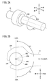
- FIG. 2A and 2B are schematic configuration diagrams of the grip handle (operation unit) in FIG. It is explanatory drawing of a neutral position and a neutral area.
- 4A and 4B are schematic configuration diagrams showing modified examples of FIGS. 2A and 2B.
- FIG. 2 is a state transition diagram of the operation of the flying object of FIG. 1.
- 7 is a flowchart illustrating a transition between a forward acceleration state and a forward deceleration state in FIG. 6.
- 7 is a flowchart illustrating a transition from a forward acceleration state to an emergency stop state in FIG. 6.
- 7 is a flowchart illustrating a transition between a forward deceleration state and an emergency stop state in FIG. 6.
- 7 is a flowchart illustrating a transition from a forward deceleration state to a hovering state in FIG. 6. It is a state transition diagram of the modification of FIG.
- the flying object 10 is a multicopter having a rectangular main body frame 12 that is long in the front-rear direction.
- the main body frame 12 includes a skeleton 14 in which a plurality of rod-shaped members such as pipe members are combined in a rectangular parallelepiped, and eight exterior panels 16 attached to the skeleton 14 so as to cover each surface of the skeleton 14. It is comprised including. In addition, a part of the skeleton 14 is exposed to the outside from the exterior panel 16.
- a boarding seat 20 on which the occupant 18 sits is provided at an upper portion of the main body frame 12.
- front and rear, left and right, and up and down directions will be described when viewed from the occupant 18 seated on the seat 20.
- components arranged on the left and right may be described with reference numerals followed by “L” for left or “R” for right.
- a steering device 22 is provided in front of the seat 20.
- the steering device 22 has a steering handle 24 that can be steered by the occupant 18, and a grip handle (an operation unit) that the occupant 18 grips with left and right hands 25 ⁇ / b> L and 25 ⁇ / b> R is provided at both left and right ends of the steering handle 24.
- 26L and 26R are provided.
- Steps 28 are provided on both left and right sides of the main body frame 12 as footrests for the occupant 18 sitting on the seat 20.
- a wind hood 30 made of a transparent acrylic plate or the like is mounted in front of the control device 22 of the main body frame 12.
- Leg-shaped landing gears 32 are attached to the lower part of the main body frame 12 at four positions in front, rear, left and right.
- the left front support arm 34L is an arm member extending forward and left from the skeleton 14, and includes an upper arm 36L extending forward and left from an upper left corner of the skeleton 14, and an upper arm 36L extending from a lower left corner of the skeleton 14. It has a lower arm 38L extending to the front left side in parallel with 36L, and a connecting rod 40L for connecting the distal end of the upper arm 36L and the distal end of the lower arm 38L.
- the right front support arm 34R is an arm member extending to the front right from the skeleton 14, and includes an upper arm 36R extending from the upper right corner of the skeleton 14 to the front right and a lower right corner of the skeleton 14. It has a lower arm 38R extending forward and to the right in parallel with the upper arm 36R, and a connecting rod 40R for connecting the distal end of the upper arm 36R and the distal end of the lower arm 38R.
- Electric motors 44L, 44R are attached downward to the intermediate portions of the left and right upper arms 36L, 36R via mount members 42L, 42R.
- the output shafts of the electric motors 44L, 44R extending downward are horizontally mounted with two wings 46L, 46R having the output shaft as a center of rotation.
- electric motors 50L, 50R are mounted upward at intermediate portions between the left and right lower arms 38L, 38R via mount members 48L, 48R.
- the output shafts of the electric motors 50L, 50R extending upward are horizontally mounted with two rotating blades 52L, 52R around the output shafts.
- a front guard member 54 is attached to the front of the main body frame 12.
- the front guard member 54 is a plate-like member having both ends fixed to the main body frame 12 and having an oval shape extending in the left-right direction so as to surround the four rotors 46L, 46R, 52L, 52R.
- connecting rods 40L and 40R are connected to both left and right sides of the front portion of the front guard member 54.
- a pair of left and right rear support arms 56L, 56R, four rotors 58L, 58R, 60L, 60R, and a rear guard member 62 are provided at the rear of the skeleton 14.
- a pair of left and right rear support arms 56L, 56R, four rotors 58L, 58R, 60L, 60R, and a rear guard member 62 are respectively a pair of left and right front support arms 34L, 34R, and four front rotors 46L. , 46R, 52L, 52R, and the front guard member 54.
- the left rear support arm 56L is an arm member made of a rod-shaped member such as a pipe material extending to the rear left from the skeleton 14, and includes an upper arm 64L extending from the upper left corner of the skeleton 14 to the rear left, and a skeleton.
- a lower arm 66L extends from the lower left corner of the body 14 to the rear left side in parallel with the upper arm 64L, and a connecting rod 68L that connects the distal end of the upper arm 64L and the distal end of the lower arm 66L.
- the right rear support arm 56R is an arm member made of a rod-shaped member such as a pipe material extending to the rear right from the skeleton 14, and includes an upper arm 64R extending from the upper right corner of the skeleton 14 to the rear right and a skeleton.
- the lower arm 14 has a lower arm 66R extending from the lower right corner to the rear right side in parallel with the upper arm 64R, and a connecting rod 68R for connecting the distal end of the upper arm 64R and the distal end of the lower arm 66R.
- Electric motors 72L, 72R are attached downward to the middle portions of the left and right upper arms 64L, 64R via mount members 70L, 70R.
- the output shafts of the electric motors 72L, 72R extending downward are horizontally mounted with two wings 58L, 58R having the output shaft as the center of rotation.
- electric motors 76L and 76R are mounted upward at intermediate portions between the left and right lower arms 66L and 66R via mount members 74L and 74R.
- the output shafts of the electric motors 76L, 76R extending upward are horizontally mounted with two rotating blades 60L, 60R having the output shaft as a center of rotation.
- a rear guard member 62 is attached to a rear portion of the main body frame 12.
- the rear guard member 62 is a plate-like member having both ends fixed to the main body frame 12 and having an oval shape extending in the left-right direction so as to surround the four rotary wings 58L, 58R, 60L, 60R.
- connecting rods 68L and 68R are connected to the left and right sides of the rear portion of the rear guard member 62.
- the front and rear electric motors 44L, 44R, 50L, 50R, 72L, 72R, 76L, 76R are connected to the rotating blades 46L, 46R, 52L, 52R, 58L, 58R, 60L, 60R connected to the output shaft. Rotate individually. Specifically, the two rotating blades 46L, 46R, 52L, 52R, 58L, 58R, 60L, and 60R arranged so as to face each other in the vertical direction are rotationally driven in directions opposite to each other.
- the left rotating blades 46L, 52L, 58L, 60L and the right rotating blades 46R, 52R, 58R, 60R are arranged symmetrically with respect to a center line extending in the front-rear direction of the main body frame 12. That is, the flying object 10 has the counter-rotating rotors 46L, 46R, 52L, 52R, 58L, 58R, 60L, and 60R of a pair of left and right and left-right symmetric arrangement.
- the body frame 12 includes a flight controller (control unit) 80, load cells 82L and 82R, an inertial navigation unit (IMU) 84 including a gyro sensor, a downward distance sensor 86, and electric motors 44L, 44R, 50L, 50R, 72L, 72R. , 76L, 76R, a plurality of ESCs (Electronic Speed Controllers) 88, a battery 90, and a battery charger 94 with a connection plug 92 are attached.
- the flight controller 80 reads and executes a program stored in a memory (not shown) to control each part of the flying object 10 described later.
- FIGS. 2A and 2B are explanatory views illustrating the operation of the grip handle 26R by the occupant 18.
- the flight controller 80 controls the electric motors 44L, 44L according to the operation amount of the steering handle 24 or the grip handle 26R.
- the flight of the flying object 10 is controlled by controlling the 44R, 50L, 50R, 72L, 72R, 76L, 76R.
- flight The body 10 can be turned. Further, for example, the occupant 18 turns the right grip handle 26R with the hand 25R (hereinafter, also referred to as the right hand 25R) from the neutral position (neutral point) to the near side, that is, the P1 direction (first operation direction). Then, the flying object 10 can be caused to fly forward (forward direction, first movement direction). Further, when the passenger 18 rotates the right grip handle 26R from the neutral position to the back side, that is, the P2 direction (second operation direction), the flying object 10 is moved backward (retreat direction, second movement direction). Can be made to fly.
- the hand 25R hereinafter, also referred to as the right hand 25R
- the flying object 10 can be caused to fly forward (forward direction, first movement direction).
- the passenger 18 rotates the right grip handle 26R from the neutral position to the back side, that is, the P2 direction (second operation direction)
- the flying object 10 is moved backward (retreat direction, second movement direction). Can be made to fly.
- the control device is operated so that the same operation as the steering handle and the throttle grip of the motorcycle can be performed. 22 are configured.
- the operation device 22 has a built-in operation amount detection sensor 98 composed of a torque sensor or a rotation angle sensor.
- the operation amount detection sensor 98 detects a rotation angle of the grip handle 26R with respect to the neutral position as an operation amount (position) of the grip handle 26R by the occupant 18.
- the operation amount detection sensor 98 detects a steering angle with respect to the neutral position of the steering handle 24 when the occupant 18 steers the steering handle 24 around a vertical axis. Therefore, the flight controller 80 can control the flight of the flying object 10 based on the operation amount and the steering angle detected by the operation amount detection sensor 98.
- the grip handle 26R In a state where the occupant 18 rotates the right grip handle 26R in the P1 direction or the P2 direction, for example, when the occupant 18 releases the right hand 25R from the grip handle 26R, the occupant 18 and the grip handle 26R are rotated. Is released from the gripping force of the right hand 25R, the grip handle 26R is returned to the neutral position by a spring (not shown) or the like.
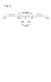
- FIG. 3 is an explanatory diagram of the operation amount (position) of the grip handle 26R by the occupant 18 (see FIGS. 1 and 2B).
- the neutral position is 0 [%]
- the operation amount when the grip handle 26R is rotated by a predetermined angle in the P1 direction (for example, +90 [°] clockwise in FIG. 2B) with respect to the neutral position is +100 [ %]
- the operation amount when the grip handle 26R is rotated by a predetermined angle in the P2 direction with respect to the neutral position eg, -90 [°] counterclockwise in FIG. 2B) is -100 [%].
- a predetermined angle in the P1 direction for example, +90 [°] clockwise in FIG. 2B
- the operation amount when the grip handle 26R is rotated by a predetermined angle in the P2 direction with respect to the neutral position is -100 [%].
- the P1 direction which is the operation direction of the grip handle 26R corresponding to the forward direction of the flying object 10 is the positive direction (+), and the grip handle corresponding to the backward direction of the flying object 10 is shown.
- the P2 direction, which is the operation direction of 26R, will be described as a negative direction (-).
- the range of + NP1 [%] in the P1 direction and the range of -NP2 [%] in the P2 direction are set to the neutral region (-NP2 [%] to + NP1 [%]) with the neutral position as the center.
- the grip handle 26R is returned to the neutral position by the force of the spring.
- the flight controller 80 sets The deceleration force in the backward direction is applied to the flying object 10 so that the speed of the flying object 10 becomes zero.
- the flight controller 80 The deceleration force in the forward direction is applied so that the speed becomes zero.
- the speed of the flying object 10 is reduced to zero by applying a deceleration force equal to or more than the air resistance value to the flying object 10.
- the flight controller 80 sets the deceleration of the flying object 10 according to the operation amount (position) of the grip handle 26R in the neutral region, the return amount, the return speed, or the return acceleration of the grip handle 26R to the neutral region. You only have to decide. For example, when the occupant 18 returns the position of the grip handle 26R largely to the neutral region with the right hand 25R, the flight controller 80 determines that the occupant 18 intends to decelerate, and the return amount, the return speed, or the return acceleration. Is larger, the deceleration may be set larger.
- the flight controller 80 may increase the deceleration as the operation amount of the grip handle 26R in the neutral region is smaller, or as the position of the grip handle 26R in the neutral region is closer to the neutral position.
- the state where the speed is 0 means a hovering state in which the flying object 10 is stopped in the air at a predetermined altitude.
- the operation amount detection sensor 98 may be difficult for the operation amount detection sensor 98 to accurately detect an operation amount (position) of 0 [%] due to a noise component. Therefore, in the neutral region, a range from ⁇ NP4 [%] to + NP3 [%] near 0 [%] may be set as a dead zone of the operation amount detection sensor 98. Therefore, the operation amount (position) detected in the range of the dead zone can be regarded as 0 [%].
- the steering device 22 is not limited to the steering handle 24 shown in FIGS. 1 to 2B, and may be replaced with, for example, the configuration shown in FIGS. 4A and 4B. Good.
- the control device 22 is configured by a lever (operation unit) 100 imitating a flight stick of an airplane.
- the vertical axis is set to the neutral position, and the occupant 18 tilts the lever 100 forward (P1 direction) around the neutral position while holding the lever 100, or moves backward (P2 direction).
- the lever 100 may be tilted.
- the steering device 22 is configured by a small lever (operation unit) 102.
- the axis extending obliquely upward and rearward is set to the neutral position, and the occupant 18 operates the lever 102 upward (P1 direction) around the neutral position while holding the lever 102, or The lever 102 may be operated to the side (P2 direction).
- the flying object 10 (see FIG. 1) can be moved forward or backward according to the operation amount (position) of the lever 100, 102 with respect to the neutral position. Also, when the levers 100 and 102 are returned to the neutral region by the force of a spring (not shown), a deceleration force can be applied to the flying object 10 that is moving forward or backward.
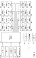
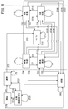
- FIG. 5 is a block diagram of the flying object 10 according to the present embodiment.
- solid lines indicate signal lines, and broken lines indicate power lines.
- the flight controller 80 controls the electric motors 44L, 44R, 50L, 50R, 72L, 72R, 76L, 76R based on the detection signals from the load cells 82L, 82R, the IMU 84, the lower distance sensor 86, and the operation amount detection sensor 98.
- An individual command signal is output to the ESC 88.
- the load cells 82L and 82R are disposed on the left and right sides immediately below the seat 20 (see FIG. 1), and the weight shift amount of the aircraft including the passenger 18 (around the longitudinal axis of the aircraft 10 (roll direction). (The amount of rotation and the amount of movement of the center of gravity).
- the IMU 84 includes a gyro sensor and detects angular velocities and accelerations (posture of the aircraft) in three axial directions.
- the lower distance sensor 86 detects the altitude of the flying object 10 from the ground surface.
- the operation amount detection sensor 98 detects the operation amount of the grip handle 26R (see FIGS. 1 and 2B) and the steering angle of the steering handle 24 as described above.
- the flight controller 80 can calculate the pitch angle (rotational angle around the horizontal axis) and the speed of the flying object 10 based on the detection result of the IMU 84, as described later. Therefore, in the present embodiment, instead of or in addition to the IMU 84, a wind speed sensor, a GPS (Global Positioning System, Global Positioning Satellite) sensor, an infrared camera, an RGB camera, a millimeter-wave radar, a LiDAR Laser, Imaging, Detection, and Ranging) may be mounted on the flying object 10, and the pitch angle and speed may be obtained based on the detection results of these detection means. In the following description, a case where the IMU 84 is mounted on the flying object 10 will be described.
- GPS Global Positioning System, Global Positioning Satellite
- Each ESC 88 individually drives the electric motors 44L, 44R, 50L, 50R, 72L, 72R, 76L, 76R based on the command signal, so that each of the rotors 46L, 46R, 52L, 52R, 58L, 58R, 60L, 60R. Are driven to rotate in individual rotation directions and rotation speeds. As a result, the flying object 10 can be made to fly in a desired direction and speed.
- the rotational speed of one of the front and rear electric motors 44L, 44R, 50L, 50R, 72L, 72R, 76L, 76R is set to the other. Lower than the rotation speed of the motor.
- the rotation speed of the rear motor may be lower than the rotation speed of the front motor.
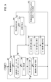
- FIG. 6 illustrates a transition of a series of operation states of the flying object 10 (see FIGS. 1 and 5), such as operation start, takeoff, flight, landing, operation end, and the like.
- FIGS. 1 and 5 illustrate the state transition diagram of FIG. 6
- the transition of the operation state of the flying object 10 will be described, and the description of the operation of each component configuring the flying object 10 may be simplified or omitted in some cases.
- the flying object 10 has landed on the surface of the ground.
- start state the state of “start”
- the flying object 10 takes off from the ground surface and rises as shown by the transition line ST1, and is in the state of "takeoff”.
- takeoff state the state of "takeoff state”.
- the flying object 10 automatically rises to the target altitude as indicated by the transition line ST2.
- the flying object 10 transits to a “hovering” state (hereinafter, also referred to as a hovering state) as indicated by a transition line ST3.
- a hovering state hereinafter, also referred to as a hovering state
- the flight controller 80 controls each unit in the flying object 10 so as to maintain the speed at 0 as indicated by the transition line ST4.
- the transition line ST4 is executed on condition that the operation amount (position) of the grip handle 26R (see FIGS. 1 to 2B) is, for example, within the neutral region.
- the flight controller 80 grasps the amount of shift of the center of gravity of the aircraft due to the shift of the weight of the occupant 18 based on the amount of shift of the weight detected by the load cells 82L and 82R. (Rotational angle around the axis in the front-rear direction). Further, the flight controller 80 controls the pitch angle based on the detection result of the IMU 84 so that the speed becomes zero. Further, the flight controller 80 controls the yaw rate according to the steering angle of the steering wheel 24 detected by the operation amount detection sensor 98. Further, the flight controller 80 controls the altitude of the flying object 10 according to the altitude of the flying object 10 detected by the downward distance sensor 86 and the operation of a button (not shown) by the passenger 18.
- the flight controller 80 outputs a command signal corresponding to the roll angle, the pitch angle, the yaw rate, and the altitude, which are the control amounts, to the respective ESCs 88, so that the electric motors 44L, 44R, 50L, 50R, 72L, 72R, 76L. , 76R, and maintains the flying object 10 in the hovering state as indicated by the transition line ST4.
- the flight controller 80 makes a transition from the hovering state to a “forward (acceleration)” state (hereinafter, also referred to as a forward acceleration state) as indicated by a transition line ST5. Accordingly, the flying object 10 flies while accelerating in the forward direction according to the operation amount (position) of the grip handle 26R by the rider 18.
- the flight controller 80 maintains the forward acceleration state as indicated by the transition line ST6. Also in this case, the flight controller 80 controls the pitch angle based on the operation amount (position) of the grip handle 26R detected by the operation amount detection sensor 98. Further, the flight controller 80 controls the roll angle and the yaw rate based on the steering angle of the steering handle 24 detected by the operation amount detection sensor 98 and the weight shift amount detected by the load cells 82L and 82R. Further, the flight controller 80 controls the altitude based on the altitude detected by the lower distance sensor 86 and the button operation by the passenger 18.
- the flight controller 80 returns to the transition line ST7. Then, the flying object 10 is changed from the forward acceleration state to the “forward (deceleration)” state (hereinafter, also referred to as forward deceleration state).
- the forward deceleration state refers to a state in which the flying object 10 is decelerated while flying in the forward direction.
- the flight controller 80 maintains the forward deceleration state as indicated by the transition line ST8.
- the flight controller 80 controls the pitch angle based on the operation amount of the grip handle 26R, similarly to the transition line ST6. Further, the flight controller 80 controls the roll angle and the yaw rate based on the steering angle of the steering handle 24 and the amount of weight shift. Further, the flight controller 80 controls the altitude based on the altitude detected by the lower distance sensor 86 and the button operation by the passenger 18.
- the flight controller 80 sets the transition line ST9 to the transition line ST9.
- the flying object 10 is shifted to the forward acceleration state.
- the operation amount (position) of the grip handle 26R is in the range of -NP2 [%] to + NP1 [%], that is, in the range of the neutral region, and the absolute value of the speed is close to zero. If it is equal to or less than the threshold, the flight controller 80 causes the flying object 10 to transition to the hovering state as indicated by a transition line ST10. That is, in consideration of the possibility that the speed 0 cannot be strictly detected due to the noise component of the IMU 84, if the absolute value of the speed in the neutral region is equal to or less than the threshold value, the speed is regarded as close to 0. Then, the state is shifted to the hovering state.
- the flight controller 80 determines that the occupant 18 Is determined to have an intention to decelerate urgently, and is shifted to a state of “emergency stop” (hereinafter, also referred to as an emergency stop state) as indicated by a transition line ST11 or ST12. That is, the emergency stop state corresponds to a sudden braking state of a vehicle such as a motorcycle, and refers to a state in which the speed is suddenly shifted to zero.
- the occupant 18 rotates the grip handle 26R in the P1 direction, and the operation amount (position) of the grip handle 26R is in the range of + NP1 [%] to +100 [%], that is, the grip handle
- the flight controller 80 determines that the occupant 18 intends to advance the flying object 10, and moves the flying object 10 as indicated by the transition line ST13. Transition to the forward acceleration state.
- the flight controller 80 determines that the passenger 18 has an intention to stop the flying object 10, and the emergency stop state is maintained as indicated by the transition line ST14. Thereby, the flying object 10 can be decelerated so that the speed quickly becomes zero.
- the flight controller 80 sets the transition line. Transition to the hovering state is made as in ST15. That is, in the emergency stop state, when the occupant 18 releases the right hand 25R from the grip handle 26R, the transition to the hovering state occurs when the grip handle 26R is in the neutral region and the absolute value of the speed is close to 0. I do.
- the flight controller 80 makes a transition to a “reverse (acceleration)” state (hereinafter, also referred to as a reverse acceleration state) as indicated by a transition line ST16.
- the backward acceleration state refers to a state in which the flying object 10 is caused to fly while being accelerated in the backward direction. Therefore, when moving the hovering flying object 10 forward (transition line ST5) or retreat (transition line ST16), the rider 18 must operate the grip handle 26R in the P1 direction or the P2 direction from the neutral region.
- the flight controller 80 determines that the occupant 18 intends to retreat the flying object 10 and makes a transition. As shown by the line ST17, the backward acceleration state is maintained. Also in this case, the flight controller 80 controls the pitch angle based on the operation amount of the grip handle 26R, similarly to the transition lines ST6 and ST8. Further, the flight controller 80 controls the roll angle and the yaw rate based on the steering angle of the steering handle 24 and the amount of weight shift. Further, the flight controller 80 controls the altitude based on the altitude detected by the lower distance sensor 86 and the button operation by the passenger 18. Note that when the speed in the reverse direction reaches a predetermined speed limit, the flight controller 80 can also limit the pitch angle to a value that matches the air resistance with respect to the speed limit.
- the flight controller 80 sets the flying object 10 to “ To the state of "reverse (deceleration)” (hereinafter also referred to as "reverse deceleration state”).
- the backward deceleration state refers to a state in which the flying object 10 flying in the backward direction is decelerated.
- the flight controller 80 Maintains the backward deceleration state as indicated by the transition line ST19. Also in this case, the flight controller 80 controls the pitch angle based on the operation amount of the grip handle 26R, similarly to the transition lines ST6, ST8, and ST17. Further, the flight controller 80 controls the roll angle and the yaw rate based on the steering angle of the steering handle 24 and the amount of weight shift. Further, the flight controller 80 controls the altitude based on the altitude detected by the lower distance sensor 86 and the button operation by the passenger 18. In this case, the acceleration in the reverse direction decreases according to the operation amount of the grip handle 26R. That is, the pitch angle is controlled in a negative range.
- the flight controller 80 shifts to the reverse acceleration state as indicated by a transition line ST20.
- the flight controller 80 Similarly to the transition from the forward deceleration state to the hovering mode (transition line ST10), the state transits to the hovering state as indicated by a transition line ST21.
- the flight controller 80 controls the flying object 10 as indicated by a transition line ST22 or ST23. Transition to the forward acceleration state.
- a forward acceleration state when the passenger 18 operates a switch (not shown) to instruct the landing of the flying object 10, the flight controller 80 performs a transition.
- the flying object 10 is transited to a “landing” state (hereinafter, also referred to as a landing state).
- the transition line ST28 is a case where the occupant 18 operates the switch before reaching the target altitude.
- the flight controller 80 controls the landing of the flying object 10 as indicated by the transition line ST29.
- the flight controller 80 sets the transition line ST30 to the transition line ST30. As shown, the flying object 10 is shifted to the forward acceleration state. Further, in the landing state, when the occupant 18 operates a switch (not shown) and the operation amount (position) of the grip handle 26R is on the P1 direction side of the neutral region, the flight controller 80 indicates a transition line ST31. Thus, the flying object 10 is shifted to the forward deceleration state.
- the flight controller 80 causes the flying object 10 to transition to the start state as indicated by the transition line ST32.
- the detected altitude may not be exactly 0 due to the noise component of the lower distance sensor 86.
- a predetermined detection range of the lower distance sensor 86 may be set to a dead zone, and the altitude may be regarded as 0 in the dead zone.
- the emergency stop state when the occupant 18 operates a switch (not shown) to instruct the landing of the flying object 10, the flight controller 80 performs the flight as shown by the transition lines ST33 to ST35.
- the body 10 is transitioned to the landing state.
- the landing state is maintained in the case of the transition line ST35.
- the flight controller 80 In the landing state, when the altitude of the flying object 10 becomes 0, the flight controller 80 causes the flying object 10 to transition to the start state as indicated by the transition line ST36. In the landing state, when the occupant 18 operates a switch (not shown) to instruct the takeoff of the flying object 10, the flight controller 80 causes the flying object 10 to transition to the takeoff state as indicated by a transition line ST37.
- FIG. 7 is a flowchart showing details of the state transition of the transition line ST7 or ST9 in FIG.
- step S1 the flight controller 80 (see FIGS. 1 and 5) determines whether the current flight state of the flying object 10 is the forward acceleration state. If the vehicle is in the forward acceleration state (step S1: YES), the process proceeds to the next step S2.
- step S2 the flight controller 80 determines whether the operation amount (position) of the grip handle 26R (see FIGS. 1 to 2B) is in the neutral region (see FIG. 3) based on the detection result of the operation amount detection sensor 98. judge. If it is the neutral region (step S2: YES), the process proceeds to the next step S3.
- step S3 the flight controller 80 sets a flag (state transition permission flag) for permitting the transition from the forward acceleration state to the forward deceleration state based on the detection results of various sensors such as the operation amount detection sensor 98. .
- the flight controller 80 sets the flag to “on (1)” when permitting the state transition, and sets the flag to “off (0)” when disallowing the state transition.
- the lower limit of the absolute value of the speed is determined by regulations or the like, and deceleration is prohibited at a speed lower than the lower limit.
- the lower limit of the absolute value of the speed is determined by regulations or the like, and deceleration is prohibited at a speed lower than the lower limit.
- step S4 the flight controller 80 determines whether the flag set in step S3 is on, that is, whether the flag is "on". If the flag is on, the process proceeds to step S5. In step S5, the flight controller 80 controls each part of the flying object 10 so that the flying object 10 transitions from the forward acceleration state to the forward deceleration state. That is, the state transition of the transition line ST7 is performed.
- step S1 the flight controller 80 returns to step S1, and executes the determination processing of step S1 again. That is, the processing in FIG. 7 is repeatedly executed during the flight of the flying object 10.
- step S4 if the flag set in step S3 is not set (step S4: NO), the flight controller 80 determines that the transition from the forward acceleration state to the forward deceleration state is impossible. Thus, the flight controller 80 returns to step S1 while maintaining the forward acceleration state.
- step S2 when the operation amount (position) of the grip handle 26R is not in the neutral region, that is, when the operation amount of the grip handle 26R is on the P1 direction side that is equal to or more than + NP1 [%] (operation amount ⁇ + NP1 [% ], Step S2: NO), and proceed to step S6.
- the flight controller 80 calculates a target pitch angle value (pitch target angle) based on the operation amount detected by the operation amount detection sensor 98.
- step S7 the flight controller 80 calculates a correction amount for the pitch target angle based on the detection results of various sensors including the operation amount detection sensor 98.
- step S8 the flight controller 80 adjusts the pitch target angle to a pitch angle according to the operation amount of the grip handle 26R by the occupant 18 by correcting the pitch target angle with the correction amount.
- the flight controller 80 outputs a command signal based on the corrected pitch target angle to each ESC 88, and controls the electric motors 44L, 44R, 50L, 50R, 72L, 72R, 76L, 76R to fly.
- the flight of the body 10 in the forward acceleration state is controlled. Thereafter, the flight controller 80 returns to Step S1.
- step S1 if the current flight state of the flying object 10 is not the forward acceleration state (step S1: NO), the process proceeds to step S9.
- step S9 the flight controller 80 determines whether the current flight state of the flying object 10 is the forward deceleration state. If the vehicle is in the forward deceleration state (step S9: YES), the process proceeds to the next step S10.
- step S10 the flight controller 80 determines whether the operation amount (position) of the grip handle 26R is on the P1 direction side (operation amount ⁇ + NP1 [%]) with respect to the neutral region.
- step S10: YES the process proceeds to step S11.
- step S11 the flight controller 80 determines that the occupant 18 has operated the grip handle 26R in the P1 direction with the intention of acceleration, and sets a flag (state transition) for permitting a transition from the forward deceleration state to the forward acceleration state. Permission flag). Even in this case, the flight controller 80 sets the flag to “on (1)” when permitting the state transition, and sets the flag to “off (0)” when disallowing the state transition. ) ".
- the upper limit of the absolute value of the speed is determined by regulations or the like, and acceleration is prohibited at a speed higher than the upper limit.
- the upper limit of the absolute value of the speed is determined by regulations or the like, and acceleration is prohibited at a speed higher than the upper limit.
- step S12 the flight controller 80 determines whether the flag set in step S11 is on, that is, whether the flag is “on”. When the flag is set (step S12: YES), the process proceeds to step S13.
- step S13 the flight controller 80 controls each part of the flying object 10 so that the flying object 10 transitions from the forward deceleration state to the forward acceleration state. That is, the state transition of the transition line ST9 is performed. Thereafter, the flight controller 80 returns to Step S1.
- step S12 determines that transition from the forward deceleration state to the forward acceleration state is impossible, and the flight controller 80 maintains the forward deceleration state while step S1.
- step S10 when the operation amount (position) of the grip handle 26R is not on the P1 direction side of the neutral region, for example, when the operation amount of the grip handle 26R is in the neutral region (step S10: NO), steps S6 to S6 are performed.
- the processing of S8 is performed in order. Thereby, the flight controller 80 can continuously perform the flight control in the forward deceleration state.
- step S9 if the current flight state of the flying object 10 is not the forward deceleration state (step S9: NO), the process proceeds to step S14.
- step S14 the flight controller 80 determines that the current flight state of the flying object 10 is a state other than the forward state, that is, the hovering state or the retreat state, and controls the flight of the flying object 10 in the current state. . Thereafter, the flight controller 80 returns to Step S1.
- FIG. 8 is a flowchart showing details of the state transition of the transition line ST11 or ST13 in FIG.
- step S21 the flight controller 80 (see FIGS. 1 and 5) determines whether the current flight state of the flying object 10 is the forward acceleration state. If the vehicle is in the forward acceleration state (step S21: YES), the process proceeds to the next step S22.
- step S22 the flight controller 80 operates the grip handle 26R (see FIGS. 1 and 2B) in the P2 direction based on the detection result of the operation amount detection sensor 98, and the operation amount ( If (position) is in the range of -100 [%] to -NP2 [%] (step S22: YES), the process proceeds to the next step S23.
- step S23 the flight controller 80 sets a flag (state transition permission flag) for permitting transition from the forward acceleration state to the emergency stop state based on the detection results of various sensors such as the operation amount detection sensor 98. . Even in this case, the flight controller 80 sets the flag to “on (1)” when permitting the state transition, and sets the flag to “off (0)” when disallowing the state transition. I do.
- step S24 the flight controller 80 determines whether the flag set in step S23 is on, that is, whether the flag is “on”. If the flag is on, the process proceeds to step S25.
- step S25 the flight controller 80 controls each part of the flying object 10 so that the flying object 10 transitions from the forward acceleration state to the emergency stop state. That is, the state transition of the transition line ST11 is performed.
- step S21 the flight controller 80 returns to step S21, and executes the determination processing of step S21 again. 8 is also repeatedly executed during the flight of the flying object 10.
- step S24 NO
- the flight controller 80 determines that the transition from the forward acceleration state to the emergency stop state is impossible. Thereby, the flight controller 80 returns to step S21 while maintaining the forward acceleration state.
- step S22 when the operation amount (position) of the grip handle 26R is not in the range of -100 [%] to -NP2 [%], that is, the P1 direction in which the operation amount of the grip handle 26R is + NP1 [%] or more. If it is on the side (operation amount ⁇ + NP1 [%], step S22: NO), the process proceeds to step S26.
- step S26 the flight controller 80 determines that the occupant 18 intends to accelerate in the forward direction, and performs pitch control based on the operation amount detected by the operation amount detection sensor 98 as in step S6 of FIG. Calculate the target angle.
- step S27 the flight controller 80 calculates a correction amount for the pitch target angle based on the detection results of various sensors, as in step S7.
- step S28 similarly to step S8, the flight controller 80 corrects the pitch target angle with the correction amount to adjust the pitch target angle to the pitch angle according to the operation amount of the grip handle 26R by the rider 18. .
- the flight controller 80 outputs a command signal based on the corrected pitch target angle to each ESC 88, controls the electric motors 44L, 44R, 50L, 50R, 72L, 72R, 76L, 76R, Controls 10 forward acceleration flights. Thereafter, the flight controller 80 returns to Step S21.
- step S21 if the current flight state of the flying object 10 is not the forward acceleration state (step S21: NO), the process proceeds to step S29.
- step S29 the flight controller 80 determines whether the current flight state of the flying object 10 is the emergency stop state. If it is in the emergency stop state (step S29: YES), the process proceeds to the next step S30.
- step S30 the flight controller 80 operates the grip handle 26R in the P1 direction based on the detection result of the operation amount detection sensor 98, so that the operation amount (position) of the grip handle 26R is + NP1 [%]. It is determined whether it is within the range of +100 [%].
- step S30 When a negative determination result is obtained in step S30, for example, when the operation amount (position) of the grip handle 26R is -100 [%] to -NP2 [%] (step S30: NO), the next step S31. Proceed to.
- step S31 the flight controller 80 calculates the speed of the flying object 10 based on the detection results of various sensors including the IMU 84 and the like. Thereafter, the flight controller 80 performs the processing of steps S26 to S28 in order. However, in step S26, the flight controller 80 calculates the pitch target angle in consideration of the speed calculated in step S31. Thereafter, the flight controller 80 returns to Step S21.
- step S32 the flight controller 80 determines that the occupant 18 has operated the grip handle 26R in the direction P1 with the intention of moving forward, and sets a flag (state transition) for permitting a transition from the emergency stop state to the forward acceleration state. Permission flag). Even in this case, the flight controller 80 sets the flag to “on (1)” when permitting the state transition, and sets the flag to “off (0)” when disallowing the state transition. ) ".
- the absolute value of the speed may exceed the upper limit.
- step S33 the flight controller 80 determines whether the flag set in step S32 is on, that is, whether the flag is “on”. When the flag is set (step S33: YES), the process proceeds to step S34.
- step S34 the flight controller 80 controls each part of the flying object 10 so that the flying object 10 transitions from the emergency stop state to the forward acceleration state. That is, the state transition of the transition line ST13 is performed. Thereafter, the flight controller 80 returns to Step S21.
- step S33 determines that the transition from the emergency stop state to the forward acceleration state is impossible, and the flight controller 80 maintains the emergency stop state in step S21.
- step S29 If the current flight state of the flying object 10 is not the emergency stop state in step S29 (step S29: NO), the flow proceeds to step S35.
- step S35 the flight controller 80 determines that the current flight state of the flying object 10 is a state other than the forward acceleration state and the emergency stop state, that is, the hovering state and the like, and the flight of the flying object 10 in the current state. Control. Thereafter, the flight controller 80 returns to Step S21.
- FIG. 9 is a flowchart showing details of the state transition of the transition line ST12 in FIG.
- step S41 the flight controller 80 (see FIGS. 1 and 5) determines whether the current flight state of the flying object 10 is a forward deceleration state. If the vehicle is in the forward deceleration state (step S41: YES), the process proceeds to the next step S42.
- step S42 the flight controller 80 operates the grip handle 26R (see FIGS. 1 to 2B) in the P2 direction based on the detection result of the operation amount detection sensor 98, and the operation amount ( If (position) is in the range of -100 [%] to -NP2 [%] (step S42: YES), the process proceeds to the next step S43.
- step S43 the flight controller 80 sets a flag (state transition permission flag) for permitting the transition from the forward deceleration state to the emergency stop state based on the detection results of various sensors such as the operation amount detection sensor 98. . Also in this case, the flight controller 80 sets the flag to “on (1)” when permitting the state transition, and sets the flag to “off (0)” when disallowing the state transition. I do.
- a flag state transition permission flag
- the transition from the forward deceleration state to the emergency stop state is not permitted, for example, when there is an obstacle in front of the flying object 10 and it is predicted that an emergency stop will collide with the obstacle is there.
- step S44 the flight controller 80 determines whether the flag set in step S43 is on, that is, whether the flag is "on". If the flag is on, the process proceeds to step S45.
- step S45 the flight controller 80 controls each part of the flying object 10 so as to transition the flying object 10 from the forward deceleration state to the emergency stop state. That is, the state transition of the transition line ST12 is performed.
- step S41 the flight controller 80 returns to step S41, and executes the determination processing of step S41 again.
- the process of FIG. 9 is also repeatedly executed during the flight of the flying object 10.
- step S44 if the flag set in step S43 is not set (step S44: NO), the flight controller 80 determines that transition from the forward deceleration state to the emergency stop state is impossible. Thereby, the flight controller 80 returns to step S41 while maintaining the forward deceleration state.
- step S42 when the operation amount (position) of the grip handle 26R is not in the range of -100 [%] to -NP2 [%], that is, the P1 direction in which the operation amount of the grip handle 26R is + NP1 [%] or more. If it is on the side (operation amount ⁇ + NP1 [%], step S42: NO), the process proceeds to step S46.
- step S46 the flight controller 80 determines that the occupant 18 intends to fly in the forward direction, and performs the operation detected by the operation amount detection sensor 98 similarly to step S6 in FIG. 7 and step S26 in FIG. A pitch target angle is calculated based on the quantity.
- step S47 the flight controller 80 calculates a correction amount for the pitch target angle based on the detection results of various sensors, as in steps S7 and S27.
- step S48 the flight controller 80 corrects the pitch target angle with the correction amount in the same manner as in steps S8 and S28, so that the pitch target angle becomes the pitch angle according to the operation amount of the grip handle 26R by the rider 18. adjust. Also in this case, the flight controller 80 outputs a command signal based on the corrected pitch target angle to each ESC 88, controls the electric motors 44L, 44R, 50L, 50R, 72L, 72R, 76L, 76R, and Control the flight of 10 forward deceleration states. Thereafter, the flight controller 80 returns to Step S41.
- step S41 if the current flight state of the flying object 10 is not the forward deceleration state (step S41: NO), the process proceeds to step S49.
- step S49 the flight controller 80 determines whether the current flight state of the flying object 10 is the emergency stop state. If it is in the emergency stop state (step S49: YES), the process proceeds to the next step S50.
- step S50 the flight controller 80 calculates the speed of the flying object 10 based on the detection results of various sensors including the IMU 84 and the like, as in step S31 of FIG. Thereafter, the flight controller 80 performs the processing of steps S46 to S48 in order. Also in this case, in step S46, the flight controller 80 calculates the pitch target angle in consideration of the speed calculated in step S50. Thereafter, the flight controller 80 returns to Step S41.
- step S49 when the current flying state of the flying object 10 is not the emergency stop state (step S49: NO), the process proceeds to step S51.
- step S51 the flight controller 80 determines that the current flight state of the flying object 10 is a state other than the forward deceleration state and the emergency stop state, that is, the hovering state or the retreat state, and the like. Control 10 flights. Thereafter, the flight controller 80 returns to Step S41.
- FIG. 10 is a flowchart showing details of the state transition of the transition line ST10 in FIG.
- step S61 the flight controller 80 (see FIGS. 1 and 5) determines whether the current flight state of the flying object 10 is a forward deceleration state. If the vehicle is in the forward deceleration state (step S61: YES), the process proceeds to the next step S62.
- step S62 the flight controller 80 operates the grip handle 26R (see FIGS. 1 and 2B) in the P2 direction based on the detection result of the operation amount detection sensor 98, and the operation amount ( Position) is smaller than the threshold value, specifically, it is determined whether the operation amount is returned to the neutral region (see FIG. 3). If it is less than the threshold value (step S62: YES), the process proceeds to the next step S63.
- step S63 the flight controller 80 calculates the speed of the flying object 10 based on the detection results of various sensors such as the IMU 84.
- step S64 the flight controller 80 determines whether the calculated absolute value of the speed is less than the threshold, that is, whether the absolute value of the speed is in the dead zone. If it is less than the threshold value (step S64: YES), the process proceeds to the next step S65.
- step S65 the flight controller 80 sets a flag (state transition permission flag) for permitting the transition from the forward deceleration state to the hovering state based on the detection results of various sensors such as the operation amount detection sensor 98. Also in this case, the flight controller 80 sets the flag to “on (1)” when permitting the state transition, and sets the flag to “off (0)” when disallowing the state transition. I do.
- a flag state transition permission flag
- the transition from the forward deceleration state to the hovering state is not permitted, for example, when there is an obstacle in front of the flying object 10 and it is predicted that the hovering state will collide with the obstacle, is there.
- step S66 the flight controller 80 determines whether the flag set in step S65 is on, that is, whether the flag is "ON". If the flag is on, the process proceeds to step S67.
- step S67 the flight controller 80 controls each part of the flying object 10 so that the flying object 10 transitions from the forward deceleration state to the hovering state. That is, the state transition of the transition line ST10 is performed.
- step S61 the flight controller 80 returns to step S61, and executes the determination processing of step S61 again.
- the process of FIG. 10 is also repeatedly executed during the flight of the flying object 10.
- step S66 when the flag set in step S65 is not set (step S66: NO), the flight controller 80 determines that the transition from the forward deceleration state to the hovering state is impossible. Thereby, the flight controller 80 returns to step S61 while maintaining the forward deceleration state.
- step S68 the flight controller 80 determines that the occupant 18 intends to advance the flying object 10, and detects the operation amount similarly to step S6 in FIG. 7, step S26 in FIG. 8, and step S46 in FIG.
- the pitch target angle is calculated based on the operation amount detected by the sensor 98.
- step S69 the flight controller 80 calculates a correction amount for the pitch target angle based on the detection results of various sensors, as in steps S7, S27, and S47.
- step S70 the flight controller 80 corrects the pitch target angle with the correction amount in the same manner as in steps S8, S28, and S48, and sets the pitch target angle to the pitch according to the operation amount of the grip handle 26R by the occupant 18. Adjust to an angle. Also in this case, the flight controller 80 outputs a command signal based on the corrected pitch target angle to each ESC 88, controls the electric motors 44L and 44R, and controls the flight of the flying object 10 in the forward deceleration state. Thereafter, the flight controller 80 returns to Step S61.
- step S61 the flight controller 80 determines whether the current flight state of the flying object 10 is a hovering state. If it is in the hovering state (step S71: YES), the process proceeds to the next step S72.
- step S72 the flight controller 80 calculates the speed of the flying object 10 based on the detection results of various sensors including the IMU 84 and the like. Thereafter, the flight controller 80 performs the processing of steps S68 to S70 in order. However, in step S68, the flight controller 80 calculates the pitch target angle in consideration of the speed calculated in step S72. Thereafter, the flight controller 80 returns to Step S61.
- step S71 if the current flying state of the flying object 10 is not the hovering state (step S71: NO), the process proceeds to step S73.
- step S73 the flight controller 80 determines that the current flight state of the flying object 10 is a state other than the forward deceleration state and the hovering state, that is, an emergency stop state or a retreat state, and the like. Control 10 flights. Thereafter, the flight controller 80 returns to Step S61.
- FIG. 11 is a modification of the state transition diagram of FIG. FIG. 11 differs from FIG. 6 in that the emergency stop state does not exist. Therefore, in FIG. 11, the transition lines ST11 to ST15 and ST34 related to the emergency stop state are omitted, and transition lines ST38 to ST41 are added instead.
- Transition line ST38 is a transition line from the forward acceleration state to the backward acceleration state
- transition line ST39 is a transition line from the forward deceleration state to the backward acceleration state.
- the operation amount (position) of the grip handle 26R in the forward acceleration state or the forward deceleration state, is on the P2 direction side of the neutral region (see FIG. 3). In this case, a state transition to the reverse acceleration state is performed.
- Transition line ST40 is a transition line from the backward deceleration state to the forward deceleration state.
- the reverse deceleration state when the operation amount (position) of the grip handle 26R is returned to the neutral region and the speed of the flying object 10 (see FIGS. 1 and 5) is greater than 0 in the forward direction, A state transition to the forward deceleration state is performed.
- the flying object 10 when the flying object 10 is flying forward in the forward acceleration state and the occupant 18 returns the operation amount (position) of the grip handle 26R to a range on the P2 direction side of the neutral region, the flying object 10 Transition to the reverse acceleration state, and fly in the reverse direction. Thereafter, when the occupant 18 returns the grip handle 26R to the P1 direction side and the operation amount of the grip handle 26R is in the neutral region, the flying object 10 may transition to the reverse deceleration state and fly. In this case, since the occupant 18 has returned the operation amount of the grip handle 26R to the neutral region, it is considered that the occupant 18 intends to decelerate the flying object 10. Therefore, even when the flying object 10 is tilted forward and is set in the reverse deceleration state, the flight backward is still continued. In such a case, the flying object 10 is promptly shifted to the forward deceleration state.
- Transition line ST41 is a transition line from the forward deceleration state to the reverse deceleration state.
- the forward deceleration state when the operation amount (position) of the grip handle 26R is returned to the neutral region and the speed of the flying object 10 is greater than 0 in the reverse direction, the state transition to the reverse deceleration state is performed. Done.
- the flying object 10 includes the grip handle 26R or the lever 100 or 102 (operation unit) operated by the occupant 18 and the grip by the occupant 18.
- the grip handle 26R or the levers 100 and 102 move in the P1 direction (first operation direction) with respect to the neutral position or in the P2 direction (second operation direction) different from the P1 direction with respect to the neutral position.
- a predetermined range in the P1 direction and the P2 direction centering on the neutral position is set as the neutral region.
- the flight controller 80 moves the flying object 10 in the forward direction (first movement direction) in accordance with the operation amount of the grip handle 26R or the levers 100 and 102 from the neutral position in the P1 direction.
- the flying object 10 is moved in a retreating direction (second moving direction) different from the advancing direction according to the operation amount of the grip handle 26R or the levers 100 and 102 from the position to the P2 direction.
- the flight controller 80 decelerates the flying object 10 when the position of the grip handle 26R or the levers 100 and 102 operated in the P1 direction or the P2 direction is displaced to the neutral region.
- the flight controller 80 decelerates the flying object 10 when the rider 18 operates the grip handle 26R or the levers 100 and 102 from the P1 direction or the P2 direction to the neutral region.
- the flying object 10 is decelerated. Can be appropriately flown.
- the flight controller 80 10 may be decelerated.
- the flying object 10 can be decelerated to transition to the hovering state. As a result, fail safe can be easily and easily realized.
- the flight controller 80 may determine the deceleration of the flying object 10 according to the return amount, the return speed, or the return acceleration of the grip handle 26R or the levers 100 and 102 from the P1 direction or the P2 direction to the neutral region.
- the flying object 10 can be accurately decelerated according to the intention of the passenger 18, such as increasing the deceleration as the return amount, the return speed, or the return acceleration increases.
- the flight controller 80 may determine the deceleration of the flying object 10 according to the operation amount or the position of the grip handle 26R or the levers 100 and 102 in the neutral region. Thus, when the occupant 18 returns the operation amount or the position of the grip handle 26R or the levers 100 and 102 to the neutral region, the flying object 10 can be reliably decelerated.
- the operation amount of the grip handle 26R or the levers 100 and 102 in the neutral region is smaller, or as the position of the grip handle 26R or the levers 100 and 102 in the neutral region is closer to the neutral position,
- the deceleration of the flying object 10 may be increased. Thereby, the discomfort of the occupant 18 due to the deceleration of the flying object 10 is reduced, and the occupant 18 can operate the flying object 10 with the same feeling as a vehicle such as a motorcycle.
- the P1 direction and the P2 direction are opposite to each other around the neutral position, and the forward direction and the backward direction, which are the traveling directions of the flying object 10, are opposite to each other. Thereby, the occupant 18 can fly the flying object 10 by operating the grip handle 26R or the levers 100 and 102 without feeling uncomfortable.
- the grip handle 26R is rotated in the P1 direction or the P2 direction about the neutral position while the occupant 18 is gripping, while the levers 100 and 102 are moved in the P1 direction or the P2 direction about the neutral position. Operated in the direction.
- the passenger 18 can easily operate the grip handle 26R or the levers 100 and 102 to fly the flying object 10.
- the present invention is not limited to the above-described embodiment, but may, of course, adopt various configurations based on the description in this specification.
Landscapes
- Engineering & Computer Science (AREA)
- Aviation & Aerospace Engineering (AREA)
- Automation & Control Theory (AREA)
- Physics & Mathematics (AREA)
- General Physics & Mathematics (AREA)
- Radar, Positioning & Navigation (AREA)
- Remote Sensing (AREA)
- Chemical & Material Sciences (AREA)
- Combustion & Propulsion (AREA)
- Control Of Position, Course, Altitude, Or Attitude Of Moving Bodies (AREA)
- Mechanical Engineering (AREA)
- Motorcycle And Bicycle Frame (AREA)
Abstract
L'invention concerne un aéronef (10) et un procédé de commande pour celui-ci, dans lesquels une plage prescrite dans une direction P1 et une direction P2 qui sont centrées sur une position neutre est établie comme étant une zone neutre pour une poignée de saisie (26D). En fonction de la position ou de la quantité d'actionnement de la poignée de saisie (26D), un dispositif de commande de vol (80) fait avancer ou reculer l'aéronef (10). Quand la poignée de saisie (26D) utilisée dans la direction P1 ou la direction P2 est entrée dans la zone neutre, le dispositif de commande de vol (80) fait décélérer l'aéronef (10).
Priority Applications (2)
| Application Number | Priority Date | Filing Date | Title |
|---|---|---|---|
| US17/251,830 US20210253261A1 (en) | 2018-06-19 | 2019-06-18 | Aircraft and control method for same |
| JP2020525748A JP6986632B2 (ja) | 2018-06-19 | 2019-06-18 | 飛行体及びその制御方法 |
Applications Claiming Priority (2)
| Application Number | Priority Date | Filing Date | Title |
|---|---|---|---|
| JP2018-115884 | 2018-06-19 | ||
| JP2018115884 | 2018-06-19 |
Publications (1)
| Publication Number | Publication Date |
|---|---|
| WO2019244892A1 true WO2019244892A1 (fr) | 2019-12-26 |
Family
ID=68983834
Family Applications (1)
| Application Number | Title | Priority Date | Filing Date |
|---|---|---|---|
| PCT/JP2019/024116 Ceased WO2019244892A1 (fr) | 2018-06-19 | 2019-06-18 | Aéronef et procédé de commande pour celui-ci |
Country Status (3)
| Country | Link |
|---|---|
| US (1) | US20210253261A1 (fr) |
| JP (1) | JP6986632B2 (fr) |
| WO (1) | WO2019244892A1 (fr) |
Cited By (5)
| Publication number | Priority date | Publication date | Assignee | Title |
|---|---|---|---|---|
| US11377220B1 (en) | 2021-09-27 | 2022-07-05 | Hoversurf, Inc. | Methods of increasing flight safety, controllability and maneuverability of aircraft and aircraft for implementation thereof |
| US11383831B1 (en) * | 2021-06-01 | 2022-07-12 | Hoversurf, Inc. | Methods of vertical take-off/landing and horizontal straight flight of aircraft and aircraft for implementation |
| US20220380035A1 (en) * | 2021-06-01 | 2022-12-01 | Hoversurf, Inc. | Methods of vertical take-off/landing and horizontal straight flight of aircraft and aircraft for implementation |
| US11541999B2 (en) | 2021-06-01 | 2023-01-03 | Hoversurf, Inc. | Methods of vertical take-off/landing and horizontal straight flight of aircraft and aircraft for implementation |
| US12221210B2 (en) | 2021-10-25 | 2025-02-11 | Levanta Tech Inc. | Wing-in-ground effect vehicles and uses thereof |
Families Citing this family (4)
| Publication number | Priority date | Publication date | Assignee | Title |
|---|---|---|---|---|
| US11447261B2 (en) * | 2020-01-24 | 2022-09-20 | Disney Enterprises, Inc. | Untethered robot with hybrid air and water power for hovering and quick airborne movements |
| SI26272A (sl) * | 2022-11-18 | 2023-05-31 | DEA Motorsport technologies d.o.o. | Vozni sistem zrakoplova in postopek njegove uporabe |
| US12168510B2 (en) * | 2023-02-07 | 2024-12-17 | Hunter William KOWALD | Compact personal flight vehicle |
| US12589860B2 (en) * | 2024-02-29 | 2026-03-31 | Keith Lacabe | Intuitive-flight control system |
Citations (4)
| Publication number | Priority date | Publication date | Assignee | Title |
|---|---|---|---|---|
| US5738302A (en) * | 1996-04-02 | 1998-04-14 | Freeland; Verne L. | Airborne vehicle |
| WO2014195660A1 (fr) * | 2013-06-06 | 2014-12-11 | Cvr Limited | Plateforme volante |
| JP2015101171A (ja) * | 2013-11-25 | 2015-06-04 | 李宏富 | H型構造のヘリコプター |
| WO2017174944A1 (fr) * | 2016-04-08 | 2017-10-12 | Zipair | Dispositif de propulsion d'un passager |
-
2019
- 2019-06-18 US US17/251,830 patent/US20210253261A1/en not_active Abandoned
- 2019-06-18 JP JP2020525748A patent/JP6986632B2/ja active Active
- 2019-06-18 WO PCT/JP2019/024116 patent/WO2019244892A1/fr not_active Ceased
Patent Citations (4)
| Publication number | Priority date | Publication date | Assignee | Title |
|---|---|---|---|---|
| US5738302A (en) * | 1996-04-02 | 1998-04-14 | Freeland; Verne L. | Airborne vehicle |
| WO2014195660A1 (fr) * | 2013-06-06 | 2014-12-11 | Cvr Limited | Plateforme volante |
| JP2015101171A (ja) * | 2013-11-25 | 2015-06-04 | 李宏富 | H型構造のヘリコプター |
| WO2017174944A1 (fr) * | 2016-04-08 | 2017-10-12 | Zipair | Dispositif de propulsion d'un passager |
Cited By (7)
| Publication number | Priority date | Publication date | Assignee | Title |
|---|---|---|---|---|
| US11383831B1 (en) * | 2021-06-01 | 2022-07-12 | Hoversurf, Inc. | Methods of vertical take-off/landing and horizontal straight flight of aircraft and aircraft for implementation |
| US20220380035A1 (en) * | 2021-06-01 | 2022-12-01 | Hoversurf, Inc. | Methods of vertical take-off/landing and horizontal straight flight of aircraft and aircraft for implementation |
| WO2022256217A1 (fr) * | 2021-06-01 | 2022-12-08 | Hoversurf, Inc. | Procédés de décollage vertical/d'atterrissage et de vol rectiligne horizontal d'aéronef et aéronef pour la mise en œuvre |
| US11541999B2 (en) | 2021-06-01 | 2023-01-03 | Hoversurf, Inc. | Methods of vertical take-off/landing and horizontal straight flight of aircraft and aircraft for implementation |
| US11377220B1 (en) | 2021-09-27 | 2022-07-05 | Hoversurf, Inc. | Methods of increasing flight safety, controllability and maneuverability of aircraft and aircraft for implementation thereof |
| US12221210B2 (en) | 2021-10-25 | 2025-02-11 | Levanta Tech Inc. | Wing-in-ground effect vehicles and uses thereof |
| US12606302B2 (en) | 2021-10-25 | 2026-04-21 | Levanta Tech Inc. | Wing-in-ground effect vehicles and uses thereof |
Also Published As
| Publication number | Publication date |
|---|---|
| JP6986632B2 (ja) | 2021-12-22 |
| JPWO2019244892A1 (ja) | 2021-03-18 |
| US20210253261A1 (en) | 2021-08-19 |
Similar Documents
| Publication | Publication Date | Title |
|---|---|---|
| JP6986632B2 (ja) | 飛行体及びその制御方法 | |
| WO2019244893A1 (fr) | Aéronef et son procédé de commande | |
| US8777152B2 (en) | Method and an aircraft provided with a swiveling tail rotor | |
| CN113631470B (zh) | 跨骑型车辆的驾驶支援装置 | |
| CN104960666B (zh) | 一种纵列双涵道飞行车辆的可倾转矢量控制辅助系统 | |
| US11498675B2 (en) | Land-and-air vehicle | |
| CN116529159A (zh) | Vtol飞行器飞行控制操纵器的系统和方法 | |
| US11556139B2 (en) | Aerial vehicles and control therefor | |
| JPWO2020202283A1 (ja) | 鞍乗り型車両の運転支援装置 | |
| WO2020202262A1 (fr) | Dispositif d'aide à la conduite pour véhicule du type à selle | |
| US6671598B2 (en) | Electrical steering for vehicle | |
| EP3891043A1 (fr) | Véhicule inclinable à auto-équilibrage pourvu de deux moteurs électriques d'entraînement | |
| WO2019102997A1 (fr) | Véhicule | |
| CN112566843B (zh) | 飞翔体控制装置、飞翔体和程序 | |
| US20250368317A1 (en) | Systems, methods, and devices for operation of a vehicle | |
| WO2019059333A1 (fr) | Motocyclette | |
| WO2021140555A1 (fr) | Dispositif et procédé de commande d'aéronef | |
| WO2021070261A1 (fr) | Véhicule volant | |
| JP5531414B2 (ja) | 操縦支援装置 | |
| Gursky et al. | Novel steering concepts for personal aerial vehicles | |
| JP2023128564A (ja) | 飛行体、及び飛行体の制御方法 | |
| WO2023167130A1 (fr) | Aéronef | |
| JP2002127992A (ja) | 飛行機の動翼作動装置 | |
| CN114585560A (zh) | 飞行体 |
Legal Events
| Date | Code | Title | Description |
|---|---|---|---|
| 121 | Ep: the epo has been informed by wipo that ep was designated in this application |
Ref document number: 19822084 Country of ref document: EP Kind code of ref document: A1 |
|
| ENP | Entry into the national phase |
Ref document number: 2020525748 Country of ref document: JP Kind code of ref document: A |
|
| NENP | Non-entry into the national phase |
Ref country code: DE |
|
| 122 | Ep: pct application non-entry in european phase |
Ref document number: 19822084 Country of ref document: EP Kind code of ref document: A1 |