WO2020003365A1 - Dispositif de ventilation à échange de chaleur - Google Patents
Dispositif de ventilation à échange de chaleur Download PDFInfo
- Publication number
- WO2020003365A1 WO2020003365A1 PCT/JP2018/024083 JP2018024083W WO2020003365A1 WO 2020003365 A1 WO2020003365 A1 WO 2020003365A1 JP 2018024083 W JP2018024083 W JP 2018024083W WO 2020003365 A1 WO2020003365 A1 WO 2020003365A1
- Authority
- WO
- WIPO (PCT)
- Prior art keywords
- temperature
- air
- heat exchange
- exhaust
- air supply
- Prior art date
- Legal status (The legal status is an assumption and is not a legal conclusion. Google has not performed a legal analysis and makes no representation as to the accuracy of the status listed.)
- Ceased
Links
Images



Classifications
-
- F—MECHANICAL ENGINEERING; LIGHTING; HEATING; WEAPONS; BLASTING
- F24—HEATING; RANGES; VENTILATING
- F24F—AIR-CONDITIONING; AIR-HUMIDIFICATION; VENTILATION; USE OF AIR CURRENTS FOR SCREENING
- F24F11/00—Control or safety arrangements
- F24F11/70—Control systems characterised by their outputs; Constructional details thereof
- F24F11/80—Control systems characterised by their outputs; Constructional details thereof for controlling the temperature of the supplied air
-
- F—MECHANICAL ENGINEERING; LIGHTING; HEATING; WEAPONS; BLASTING
- F24—HEATING; RANGES; VENTILATING
- F24F—AIR-CONDITIONING; AIR-HUMIDIFICATION; VENTILATION; USE OF AIR CURRENTS FOR SCREENING
- F24F7/00—Ventilation
- F24F7/04—Ventilation with ducting systems, e.g. by double walls; with natural circulation
- F24F7/06—Ventilation with ducting systems, e.g. by double walls; with natural circulation with forced air circulation, e.g. by fan positioning of a ventilator in or against a conduit
- F24F7/08—Ventilation with ducting systems, e.g. by double walls; with natural circulation with forced air circulation, e.g. by fan positioning of a ventilator in or against a conduit with separate ducts for supplied and exhausted air with provisions for reversal of the input and output systems
Definitions
- the present invention relates to a heat exchange ventilator for exchanging heat between an exhaust flow for discharging indoor air to the outside of a room and an air supply flow for supplying outdoor air to the room.
- a preheater may be installed on an air passage leading from the outside air intake of the building to the intake of the heat exchange ventilator to take measures to increase the temperature of the outside air taken into the heat exchange ventilator.
- Patent Document 1 discloses a heat exchange ventilator that operates a pre-heater when a temperature detected by a suction temperature sensor provided in the heat exchange ventilator does not exceed a certain threshold temperature.
- the heat exchange ventilator disclosed in Patent Literature 1 stops the operation of the preheater when the suction temperature of the heat exchange ventilator rises and exceeds a threshold due to an increase in outside air temperature or the like.
- the heat exchange ventilator disclosed in Patent Literature 1 discloses that, even if the suction temperature exceeds the threshold, if the outside air temperature is not sufficiently increased, when the preheater stops operating, the suction temperature again increases to the threshold temperature. It may be as follows. In this case, in the heat exchange ventilation device disclosed in Patent Document 1, the operation of the preheater is restarted. The heat exchange ventilation device disclosed in Patent Literature 1 sometimes repeats the operation and stop of the preheater.
- the present invention has been made in view of the above, and an object of the present invention is to provide a heat exchange ventilator capable of suppressing low-temperature air from entering a housing.
- the present invention provides an air supply blower that generates an air supply flow, an exhaust air blower that generates an exhaust air flow, and performs heat exchange between the air supply flow and the exhaust air flow. It has a heat exchanger and a temperature sensor for measuring the temperature of the supply airflow. According to the present invention, a heat generated by a pre-heater that heats a supply airflow before passing through a heat exchanger based on which of a plurality of preset temperature ranges a temperature difference between a measurement result of a temperature sensor and a set temperature belongs to.
- the control unit includes a heating value setting unit for setting an amount.
- the heat exchange ventilator according to the present invention has a phenomenon in which low-temperature air is supplied to a room and a phenomenon in which low-temperature air penetrates into a housing to adversely affect electric components or cause dew condensation to occur in a heat exchange element. This has the effect that hardly occurs.
- Functional block diagram of a control unit of the heat exchange ventilation device according to Embodiment 1. Flow chart showing the flow of the operation of the heat exchange ventilation device according to the first embodiment.
- FIG. 1 is a diagram showing a configuration of a heat exchange ventilation apparatus according to Embodiment 1 of the present invention.
- an external preheater unit 2 having a preheater 18 is installed in the outside air suction duct 5.
- the preheater 18 heats the supply airflow before passing through the heat exchanger 19.
- the preheater 18 is controlled by a DC voltage signal output from the heat exchange ventilator 1.
- the heat exchange ventilator 1 includes a supply air blower 11 for generating a supply air flow, an exhaust blower 10 for generating an exhaust flow, and a heat exchanger including a heat exchange element for performing heat exchange between the supply air flow and the exhaust flow. 19, a control unit 14 for controlling the pre-heater 18, and an outside air temperature sensor 3 for measuring the temperature of the outside air OA.
- the air supply blower 11, the exhaust blower 10, and the heat exchanger 19 are housed in a housing 15.
- the housing 15 is provided with a supply air passage 16 through which a supply air flow passes and an exhaust air passage 17 through which an exhaust flow passes.
- the outside air temperature sensor 3 is installed in the air supply passage 16 upstream of the heat exchanger 19.
- the heat exchange ventilator 1 includes a return air temperature sensor 4 for measuring the temperature of the exhaust gas flow.
- the return air temperature sensor 4 is installed in the exhaust air passage 17 upstream of the heat exchanger 19.
- the air supply blower 11 sucks outside air OA from outside through the outside air suction duct 5 and blows out air supply SA into the room through the air supply duct 7 to generate a supply air flow.
- the exhaust blower 10 sucks indoor air RA from the room through the return air duct 8 and blows out the exhaust air EA to the outside through the exhaust duct 9 to generate an exhaust flow.
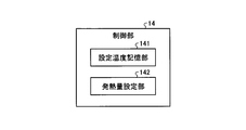
- FIG. 2 is a functional block diagram of a control unit of the heat exchange ventilation device according to Embodiment 1.
- the control unit 14 outputs a DC voltage signal to the preheater 18 based on a temperature difference between the temperature of the supply air flow and the set temperature, and a set temperature storage unit 141 that stores a set temperature serving as a reference for operation control of the preheater 18.
- a heat generation amount setting unit 142 In the first embodiment, the temperature of the supply air flow is the temperature of the outside air OA measured by the outside air temperature sensor 3.
- the set temperature stored in the set temperature storage unit 141 may be rewritable by the user.
- FIG. 3 is a flowchart showing the flow of the operation of the heat exchange ventilator according to Embodiment 1.
- the preheater 18 has five levels of heat generation, and the heat generation increases in the order of the first state, the second state, the third state, the fourth state, and the fifth state. That is, the preheater 18 is in one of the stopped state, the first state, the second state, the third state, the fourth state, and the fifth state.
- step A01 the heat generation amount setting unit 142 reads the set temperature Ta stored in the set temperature storage unit 141.
- the calorific value setting unit 142 reads the measured value of the temperature of the outside air OA from the outside air temperature sensor 3.
- the heat generation amount setting unit 142 sets the measured value of the temperature of the outside air OA read from the outside air temperature sensor 3 as the supply air flow temperature Tc.
- the heat generation amount setting unit 142 determines whether or not the supply air temperature Tc is equal to or higher than the set temperature Ta. That is, the heat generation amount setting unit 142 determines whether or not a temperature difference obtained by subtracting the set temperature Ta from the supply air temperature Tc is 0 ° C. or more.
- step A03 If the supply air temperature Tc is equal to or higher than the set temperature Ta, the result is Yes in step A03, and in step A04, the heat generation amount setting unit 142 outputs a DC voltage signal of 0 V to the pre-heater unit 2.
- the preheater 18 When a 0 V DC voltage signal is input, the preheater 18 is stopped and does not heat the supply air flow.
- the result is No in step A05, and the heat generation amount setting unit 142 outputs a DC voltage signal of 0 V to the preheater unit 2.
- the result is Yes in step A05, and the process returns to step A01.
- step A06 the heat generation amount setting unit 142 determines that the temperature difference obtained by subtracting the set temperature Ta from the supply air temperature Tc is ⁇ 5. It is determined whether the temperature is not lower than 0 ° C and lower than 0 ° C. If the temperature difference obtained by subtracting the set temperature Ta from the supply air temperature Tc is ⁇ 5 ° C. or more and less than 0 ° C., the result is Yes in step A06, and in step A07, the calorific value setting unit 142 outputs the 2V DC voltage signal to the pre-heater. Output to unit 2.
- step A06 When a DC voltage signal of 2 V is input, the preheater 18 heats the supply airflow in the first state. Until the set time elapses from the determination in step A06, the determination in step A08 is No, and the heat generation amount setting unit 142 outputs a 2V DC voltage signal to the preheater unit 2. When the set time has elapsed from the determination in step A06, the result in step A08 is Yes, and the process returns to step A01.
- step A06 If the temperature difference obtained by subtracting the set temperature Ta from the supply air temperature Tc is not less than ⁇ 5 ° C. and less than 0 ° C., the result is No in step A06, and in step A09, the heat generation amount setting unit 142 sets the temperature based on the supply air temperature Tc. It is determined whether or not the temperature difference obtained by subtracting the temperature Ta is not less than -10 ° C and less than -5 ° C. If the temperature difference obtained by subtracting the set temperature Ta from the supply air temperature Tc is ⁇ 10 ° C. or more and less than ⁇ 5 ° C., the result is Yes in step A09, and in step A10, the calorific value setting unit 142 outputs the 4V DC voltage signal.
- step A11 When a DC voltage signal of 4 V is input, the preheater 18 heats the supply airflow in the second state. From the determination in step A09 to the elapse of the set time, the determination in step A11 is No, and the heat generation amount setting unit 142 outputs a 4V DC voltage signal to the preheater unit 2. When the set time has elapsed from the determination in step A09, the result in step A11 is Yes, and the process returns to step A01.
- the calorific value setting unit 142 determines the temperature of the supply air flow Tc. It is determined whether or not the temperature difference obtained by subtracting the set temperature Ta is not less than ⁇ 15 ° C. and less than ⁇ 10 ° C. If the temperature difference obtained by subtracting the set temperature Ta from the supply air temperature Tc is ⁇ 15 ° C. or more and less than ⁇ 10 ° C., the result is Yes in step A12, and in step A13, the calorific value setting unit 142 outputs the 6 V DC voltage signal.
- the calorific value setting unit 142 calculates It is determined whether or not the temperature difference obtained by subtracting the set temperature Ta is ⁇ 20 ° C. or more and less than ⁇ 15 ° C. If the temperature difference obtained by subtracting the set temperature Ta from the supply air temperature Tc is ⁇ 20 ° C. or more and less than ⁇ 15 ° C., the result is Yes in step A15, and in step A16, the calorific value setting unit 142 outputs the 8 V DC voltage signal. Output to the pre-heater unit 2.
- step A15 When the DC voltage signal of 8 V is input, the preheater 18 heats the supply airflow in the fourth state. Until the set time elapses from the determination in step A15, the result is No in step A17, and the calorific value setting unit 142 outputs an 8V DC voltage signal to the preheater unit 2. When the set time has elapsed from the determination in step A15, the result is Yes in step A17, and the process returns to step A01.
- step A15 If the temperature difference obtained by subtracting the set temperature Ta from the supply air temperature Tc is not less than ⁇ 20 ° C. and less than ⁇ 15 ° C., the result is No in step A15, and in step A18, the calorific value setting unit 142 outputs the 10 V DC voltage signal. Output to the pre-heater unit 2.
- the preheater 18 heats the supply airflow in the fifth state.
- the heat generation amount setting unit 142 outputs a DC voltage signal of 10V to the preheater unit 2.
- the set time has elapsed from the determination in step A15, the result is Yes in step A19, and the process returns to step A01.
- the heat exchange ventilator 1 controls the preheater 18 based on a temperature difference between a measured value of the temperature of the outside air OA taken in from outside and a set temperature. Specifically, the calorific value of the pre-heater 18 is changed based on which of a plurality of preset temperature ranges contains the temperature difference between the measured value of the temperature of the outside air OA and the set temperature. Therefore, if the fluctuation of the temperature difference between the measured value of the temperature of the outside air OA and the set temperature falls within the same temperature range, the calorific value of the preheater 18 is not changed.
- the calorific value of the pre-heater 18 based on the temperature range including the temperature difference between the measured value of the temperature of the outside air OA and the set temperature, the outside air OA is hard to be excessively heated by the pre-heater 18 and heat exchange is prevented. Fluctuations in the temperature of the outside air OA taken into the housing 15 of the ventilation device 1 can be reduced. For this reason, in the heat exchange ventilator 1 according to the first embodiment, the operation and stop of the preheater 18 are repeated, so that intermittent intrusion of low-temperature air into the housing 15 can be suppressed.
- the heat exchange ventilator 1 has an adverse effect on electric components due to the event that the low-temperature supply air SA is supplied into the room and the low-temperature outside air OA entering the housing 15. An event that condensation occurs on the heat exchange element of the exchanger 19 is less likely to occur.
- FIG. FIG. 4 is a diagram illustrating a configuration of a heat exchange ventilation apparatus according to Embodiment 2 of the present invention.
- the supply air temperature sensor 12 is installed in the supply air passage 16 downstream of the heat exchanger 19.
- the temperature of the air supply flow used by the control unit 14 to control the preheater 18 is a value measured by the air supply temperature sensor 12.
- the rest is the same as the heat exchange ventilator 1 according to the first embodiment. That is, the heat exchange ventilator 1 according to Embodiment 2 executes the operation of the flowchart shown in FIG. 2 using the measurement value of the supply air temperature sensor 12.
- the heat exchange ventilator 1 controls the pre-heater 18 based on the temperature difference between the measured value of the temperature of the supply air SA supplied into the room and the set temperature. Specifically, the heat generation amount of the pre-heater 18 is changed based on which of a plurality of preset temperature ranges contains the temperature difference between the measured value of the temperature of the supply air SA and the set temperature. Therefore, if the fluctuation in the temperature difference between the measured value of the temperature of the supply air SA and the set temperature falls within the same temperature range, the amount of heat generated by the preheater 18 is not changed.
- the calorific value of the pre-heater 18 based on the temperature range including the temperature difference between the measured value of the temperature of the supply air SA and the set temperature, it becomes difficult for the pre-heater 18 to excessively heat the outside air OA.
- the fluctuation of the temperature of the outside air OA taken into the housing 15 of the exchange ventilation device 1 can be reduced.
- the heat exchange ventilator 1 according to Embodiment 2 controls the pre-heater 18 using the measured value of the temperature of the supply air SA actually supplied to the room, so that the temperature of the supply air SA supplied to the room is low. It is easy to suppress becoming.
- FIG. FIG. 5 is a diagram showing a configuration of a heat exchange ventilation apparatus according to Embodiment 3 of the present invention.
- the preheater 13 is installed in the housing 15.
- the preheater 13 is installed in the air supply passage 16 upstream of the heat exchanger 19.
- the temperature of the supply air flow used by the control unit 14 to control the preheater 13 may be either the temperature of the outside air OA measured by the outside air temperature sensor 3 or the temperature of the supply air SA measured by the supply air temperature sensor 12.
- the heat exchange ventilator 1 includes the preheater 13 in the housing, and therefore does not require wiring for connecting the control unit 14 and the preheater 13, and is easy to install and maintain.
- the function of the control unit 14 of the heat exchange ventilator 1 according to the first, second or third embodiment is realized by a processing circuit.
- the processing circuit may be dedicated hardware or a processing device that executes a program stored in a storage device.
- FIG. 6 is a diagram illustrating a configuration in which the function of the control unit of the heat exchange ventilation device according to the first, second, or third embodiment is realized by hardware.
- the processing circuit 29 incorporates a logic circuit 29a for realizing the function of the control unit 14.
- the hardware that implements the processing circuit 29 can be exemplified by a microcontroller.
- the function of the control unit 14 is realized by software, firmware, or a combination of software and firmware.
- FIG. 7 is a diagram showing a configuration in which the function of the control unit of the heat exchange ventilation apparatus according to the first, second, or third embodiment is realized by software.
- the processing circuit 29 includes an arithmetic unit 291 that executes the program 29b, a random access memory 292 used by the arithmetic unit 291 for a work area, and a storage device 293 that stores the program 29b.
- the function of the control unit 14 is realized by the arithmetic unit 291 expanding and executing the program 29b stored in the storage device 293 on the random access memory 292.
- the software or firmware is described in a programming language and stored in the storage device 293.
- the arithmetic unit 291 can be, but is not limited to, a central processing unit.
- the processing circuit 29 implements the function of the control unit 14 by reading and executing the program 29b stored in the storage device 293. It can be said that the program 29b causes a computer to execute a procedure and a method for realizing the function of the control unit 14.
- processing circuit 29 may be partially realized by dedicated hardware and partially realized by software or firmware.
- the processing circuit 29 can realize the above-described functions by hardware, software, firmware, or a combination thereof.
Landscapes
- Engineering & Computer Science (AREA)
- Chemical & Material Sciences (AREA)
- Combustion & Propulsion (AREA)
- Mechanical Engineering (AREA)
- General Engineering & Computer Science (AREA)
- Ventilation (AREA)
- Air Conditioning Control Device (AREA)
Abstract
Cette invention concerne un dispositif de ventilation à échange de chaleur (1), comprenant : un dispositif de soufflante d'alimentation en air (11) pour générer un flux d'alimentation en air ; un dispositif de soufflante d'évacuation d'air (10) pour générer un flux d'évacuation d'air ; un échangeur de chaleur (19) pour effectuer un échange de chaleur entre le flux d'alimentation en air et le flux de décharge d'air ; un capteur de température d'air externe (3) pour mesurer la température du flux d'alimentation en air ; et une unité de commande (14) comprenant une unité de réglage de quantité de génération de chaleur qui règle une quantité de génération de chaleur d'un préchauffeur (18) pour chauffer le flux d'alimentation en air avant que celui-ci ne passe à travers l'échangeur de chaleur (19), la quantité de génération de chaleur étant réglée sur la base de celle d'une pluralité de plages de température prédéfinies à laquelle appartient la différence de température entre une température de consigne et un résultat de mesure provenant du capteur de température d'air externe (3).
Priority Applications (2)
| Application Number | Priority Date | Filing Date | Title |
|---|---|---|---|
| JP2020526743A JPWO2020003365A1 (ja) | 2018-06-26 | 2018-06-26 | 熱交換換気装置 |
| PCT/JP2018/024083 WO2020003365A1 (fr) | 2018-06-26 | 2018-06-26 | Dispositif de ventilation à échange de chaleur |
Applications Claiming Priority (1)
| Application Number | Priority Date | Filing Date | Title |
|---|---|---|---|
| PCT/JP2018/024083 WO2020003365A1 (fr) | 2018-06-26 | 2018-06-26 | Dispositif de ventilation à échange de chaleur |
Publications (1)
| Publication Number | Publication Date |
|---|---|
| WO2020003365A1 true WO2020003365A1 (fr) | 2020-01-02 |
Family
ID=68984987
Family Applications (1)
| Application Number | Title | Priority Date | Filing Date |
|---|---|---|---|
| PCT/JP2018/024083 Ceased WO2020003365A1 (fr) | 2018-06-26 | 2018-06-26 | Dispositif de ventilation à échange de chaleur |
Country Status (2)
| Country | Link |
|---|---|
| JP (1) | JPWO2020003365A1 (fr) |
| WO (1) | WO2020003365A1 (fr) |
Cited By (4)
| Publication number | Priority date | Publication date | Assignee | Title |
|---|---|---|---|---|
| CN109812922A (zh) * | 2019-02-21 | 2019-05-28 | 珠海格力电器股份有限公司 | 空调器防凝露控制方法、控制装置及空调器 |
| KR20230044753A (ko) * | 2021-09-27 | 2023-04-04 | 한양대학교 산학협력단 | 환기장치용 프리히터 |
| WO2023203606A1 (fr) * | 2022-04-18 | 2023-10-26 | 三菱電機株式会社 | Dispositif de ventilation et système de ventilation |
| US20240230143A9 (en) * | 2021-05-25 | 2024-07-11 | Mitsubishi Electric Corporation | Heat-exchange ventilation apparatus and heat-exchange ventilation system |
Citations (7)
| Publication number | Priority date | Publication date | Assignee | Title |
|---|---|---|---|---|
| JPS60180939U (ja) * | 1984-05-14 | 1985-11-30 | 三菱電機株式会社 | 空調換気扇 |
| JPS63194143A (ja) * | 1987-02-06 | 1988-08-11 | Toshiba Corp | 空調換気扇 |
| US5257736A (en) * | 1992-08-06 | 1993-11-02 | Donald Roy | Self-regulating air ventilation apparatus |
| JPH06323593A (ja) * | 1993-05-19 | 1994-11-25 | Sekisui Chem Co Ltd | 熱交換型換気扇 |
| JP2004340467A (ja) * | 2003-05-15 | 2004-12-02 | Mitsubishi Electric Corp | 熱交換換気装置 |
| KR20120057919A (ko) * | 2010-11-29 | 2012-06-07 | 린나이코리아 주식회사 | 자기보호운전을 하는 환기장치 |
| JP2016169913A (ja) * | 2015-03-13 | 2016-09-23 | 三菱電機株式会社 | 熱交換換気装置 |
Family Cites Families (1)
| Publication number | Priority date | Publication date | Assignee | Title |
|---|---|---|---|---|
| JPS6022256Y2 (ja) * | 1980-05-09 | 1985-07-02 | 三菱電機株式会社 | 空調換気扇 |
-
2018
- 2018-06-26 WO PCT/JP2018/024083 patent/WO2020003365A1/fr not_active Ceased
- 2018-06-26 JP JP2020526743A patent/JPWO2020003365A1/ja active Pending
Patent Citations (7)
| Publication number | Priority date | Publication date | Assignee | Title |
|---|---|---|---|---|
| JPS60180939U (ja) * | 1984-05-14 | 1985-11-30 | 三菱電機株式会社 | 空調換気扇 |
| JPS63194143A (ja) * | 1987-02-06 | 1988-08-11 | Toshiba Corp | 空調換気扇 |
| US5257736A (en) * | 1992-08-06 | 1993-11-02 | Donald Roy | Self-regulating air ventilation apparatus |
| JPH06323593A (ja) * | 1993-05-19 | 1994-11-25 | Sekisui Chem Co Ltd | 熱交換型換気扇 |
| JP2004340467A (ja) * | 2003-05-15 | 2004-12-02 | Mitsubishi Electric Corp | 熱交換換気装置 |
| KR20120057919A (ko) * | 2010-11-29 | 2012-06-07 | 린나이코리아 주식회사 | 자기보호운전을 하는 환기장치 |
| JP2016169913A (ja) * | 2015-03-13 | 2016-09-23 | 三菱電機株式会社 | 熱交換換気装置 |
Cited By (6)
| Publication number | Priority date | Publication date | Assignee | Title |
|---|---|---|---|---|
| CN109812922A (zh) * | 2019-02-21 | 2019-05-28 | 珠海格力电器股份有限公司 | 空调器防凝露控制方法、控制装置及空调器 |
| US20240230143A9 (en) * | 2021-05-25 | 2024-07-11 | Mitsubishi Electric Corporation | Heat-exchange ventilation apparatus and heat-exchange ventilation system |
| KR20230044753A (ko) * | 2021-09-27 | 2023-04-04 | 한양대학교 산학협력단 | 환기장치용 프리히터 |
| KR102637582B1 (ko) * | 2021-09-27 | 2024-02-15 | 한양대학교 산학협력단 | 환기장치용 프리히터 |
| WO2023203606A1 (fr) * | 2022-04-18 | 2023-10-26 | 三菱電機株式会社 | Dispositif de ventilation et système de ventilation |
| JPWO2023203606A1 (fr) * | 2022-04-18 | 2023-10-26 |
Also Published As
| Publication number | Publication date |
|---|---|
| JPWO2020003365A1 (ja) | 2020-12-17 |
Similar Documents
| Publication | Publication Date | Title |
|---|---|---|
| US11549710B2 (en) | Model predictive control-based building climate controller incorporating humidity | |
| JP6514242B2 (ja) | 環境維持システムの制御方法、環境維持システム及びプログラム | |
| JPWO2020003365A1 (ja) | 熱交換換気装置 | |
| Wang et al. | Energy consumption of air conditioners at different temperature set points | |
| US10317862B2 (en) | Systems and methods for heat rise compensation | |
| Clark et al. | Efficacy of occupancy-based smart ventilation control strategies in energy-efficient homes in the United States | |
| US20190324421A1 (en) | Temperature control system and methods for operating same | |
| CN101099065A (zh) | 用于减少水分改变操作的空调设备的控制 | |
| CN105042782B (zh) | 空调器的控制方法及装置 | |
| US11493220B2 (en) | Systems and methods for heat rise compensation | |
| US20070289731A1 (en) | Method for programming and user interface for environmental control | |
| US9625177B2 (en) | Furnace controller and a furnace that controls a gas input rate to maintain a discharge air temperature | |
| US20100299563A1 (en) | Hvac system, a method for determining a source of a reset and a hvac controller configured for the same | |
| Shea et al. | Reducing university air handling unit energy usage through controls-based energy efficiency measures | |
| SG192566A1 (en) | Air conditioning apparatus and air conditioning control method | |
| CN108826622B (zh) | 一种空调器防霉控制方法、装置及空调器 | |
| CA3043996A1 (fr) | Systeme de regulation de temperature et ses procedes de fonctionnement | |
| CN109059224B (zh) | 空气调节设备的控制方法、装置和空气调节设备 | |
| CN102906957A (zh) | 用于向各个电负载顺序地施加电力的系统和方法 | |
| CN103631349A (zh) | 用于高效的数据中心冷却的系统和方法 | |
| WO2019026256A1 (fr) | Dispositif de ventilation à échange de chaleur | |
| CN116324295A (zh) | 通风系统、集成空调系统及其控制方法 | |
| JP5507275B2 (ja) | 空調制御装置 | |
| CN113093832A (zh) | 供风设备及其风温控制方法、电子设备和计算机可读介质 | |
| CN110131901A (zh) | 燃气热水器的控制方法和燃气热水器 |
Legal Events
| Date | Code | Title | Description |
|---|---|---|---|
| 121 | Ep: the epo has been informed by wipo that ep was designated in this application |
Ref document number: 18924982 Country of ref document: EP Kind code of ref document: A1 |
|
| ENP | Entry into the national phase |
Ref document number: 2020526743 Country of ref document: JP Kind code of ref document: A |
|
| NENP | Non-entry into the national phase |
Ref country code: DE |
|
| 122 | Ep: pct application non-entry in european phase |
Ref document number: 18924982 Country of ref document: EP Kind code of ref document: A1 |