WO2020003396A1 - Dispositif et procédé d'aide à la conduite - Google Patents
Dispositif et procédé d'aide à la conduite Download PDFInfo
- Publication number
- WO2020003396A1 WO2020003396A1 PCT/JP2018/024330 JP2018024330W WO2020003396A1 WO 2020003396 A1 WO2020003396 A1 WO 2020003396A1 JP 2018024330 W JP2018024330 W JP 2018024330W WO 2020003396 A1 WO2020003396 A1 WO 2020003396A1
- Authority
- WO
- WIPO (PCT)
- Prior art keywords
- lane
- vehicle
- intersection
- guidance information
- lanes
- Prior art date
- Legal status (The legal status is an assumption and is not a legal conclusion. Google has not performed a legal analysis and makes no representation as to the accuracy of the status listed.)
- Ceased
Links
Images










Classifications
-
- G—PHYSICS
- G01—MEASURING; TESTING
- G01C—MEASURING DISTANCES, LEVELS OR BEARINGS; SURVEYING; NAVIGATION; GYROSCOPIC INSTRUMENTS; PHOTOGRAMMETRY OR VIDEOGRAMMETRY
- G01C21/00—Navigation; Navigational instruments not provided for in groups G01C1/00 - G01C19/00
- G01C21/26—Navigation; Navigational instruments not provided for in groups G01C1/00 - G01C19/00 specially adapted for navigation in a road network
- G01C21/34—Route searching; Route guidance
Definitions
- the present invention relates to a driving support device and a driving support method for guiding a driver to change lanes.
- Patent Document 1 a technique of calculating or estimating a traveling route of a host vehicle in advance and guiding the host vehicle to travel in an appropriate lane before the host vehicle goes straight or turns right or left at an intersection.
- Patent Document 1 the lane in which the vehicle is traveling is recognized using a high-accuracy map database having a route regulation for each lane at an intersection and a high-accuracy location technology. Then, guidance for changing the lane of the own vehicle is provided based on the lane regulation of the lane in which the own vehicle should travel when entering the intersection and the lane regulation of other lanes.
- right-turn lanes which are dedicated lanes for vehicles to turn right, may be provided. In such a case, the number of lanes on the road at the intersection increases.
- Patent Document 1 assumes that the number of lanes on the road on which the vehicle is currently traveling is the same as the number of lanes at the intersection, and does not consider the case where the number of lanes on the road increases at the intersection. Therefore, for example, there is a problem that the lane change to the increased lane cannot be guided at an appropriate timing. As described above, conventionally, no consideration has been given to the case where the number of lanes on a road increases at an intersection, so that lane change cannot be guided at an appropriate timing.
- the present invention has been made to solve such a problem, and an object of the present invention is to provide a driving support device and a driving support method that can guide lane change at an appropriate timing.
- the driving support device is a map information acquisition unit that acquires map information including the number of lanes of a road, a point at which the number of lanes changes, and a route restriction for each lane at an intersection.
- An own vehicle traveling position recognition unit that recognizes the own vehicle traveling position including the current traveling lane and position of the own vehicle, a course calculation unit that calculates the course of the own vehicle at the intersection, and map information acquired by the map information acquisition unit;
- the lane guidance information generator includes a notification controller configured to perform notification of the lane guidance information generated by the lane guidance information generator. At least one of the route regulation acquired by the map information acquisition unit and the distance and time from the own vehicle traveling position to the first base point which is the intersection, and the second base point where the number of lanes changes from the own vehicle traveling position.
- the lane guidance information is generated based on at least one of the distance to and / or the time.
- the driving support method acquires map information including the number of lanes on a road, a point at which the number of lanes changes, and route regulation for each lane at an intersection, and the own vehicle traveling position including the current traveling lane and position of the own vehicle. Based on the acquired map information, the recognized traveling position of the own vehicle, and the calculated route, the lane including the timing and content of the lane change guidance before entering the intersection.
- Generating the guidance information, performing control to notify the generated lane guidance information, and generating the lane guidance information include calculating the route, the obtained route regulation, and the travel distance from the own vehicle traveling position to the first base point, which is the intersection. At least one of the distance and the time and at least one of the distance and the time from the own vehicle traveling position to the second base point where the number of lanes changes. Based on at least one of comprises generating lane guidance information.
- the driving support device includes: a map information acquisition unit that acquires map information including the number of lanes on a road, a point where the number of lanes changes, and a route restriction for each lane at an intersection; And an own-vehicle traveling-position recognizing unit that recognizes the own-vehicle traveling position including the position, a course calculating unit that calculates a course of the own vehicle at the intersection, and map information acquired by the map information acquiring unit, A lane guidance information generation unit that generates lane guidance information including timing and content of lane change guidance before entering an intersection based on the recognized own vehicle traveling position and the route calculated by the route calculation unit; A notification control unit that performs control for notifying the lane guidance information generated by the generation unit, and the lane guidance information generation unit obtains the route calculated by the route calculation unit and the map information acquisition unit.
- the driving support method acquires map information including the number of lanes on a road, a point at which the number of lanes changes, and route regulation for each lane at an intersection, and the own vehicle traveling position including the current traveling lane and position of the own vehicle. Based on the acquired map information, the recognized traveling position of the own vehicle, and the calculated route, the lane including the timing and content of the lane change guidance before entering the intersection.
- Generating the guidance information, performing control to notify the generated lane guidance information, and generating the lane guidance information include calculating the route, the obtained route regulation, and the travel distance from the own vehicle traveling position to the first base point, which is the intersection.
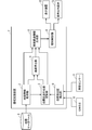
- FIG. 1 is a block diagram illustrating an example of a configuration of a driving support device according to a first embodiment of the present invention.
- 1 is a block diagram illustrating an example of a configuration of a driving support device according to a first embodiment of the present invention.
- FIG. 2 is a block diagram illustrating an example of a hardware configuration of the driving support device according to the first embodiment of the present invention.
- 5 is a flowchart illustrating an example of an operation of the driving support device according to the first embodiment of the present invention.
- FIG. 3 is a diagram showing an example of an operation of the driving support device according to the first embodiment of the present invention.
- FIG. 3 is a diagram showing an example of an operation of the driving support device according to the first embodiment of the present invention.
- FIG. 3 is a diagram showing an example of an operation of the driving support device according to the first embodiment of the present invention.
- FIG. 5 is a diagram illustrating an example of a display of a lane change according to the first embodiment of the present invention.
- FIG. 5 is a diagram illustrating an example of a display of a lane change according to the first embodiment of the present invention.
- FIG. 5 is a diagram illustrating an example of a display of a lane change according to the first embodiment of the present invention.
- FIG. 5 is a diagram illustrating an example of a display of a lane change according to the first embodiment of the present invention.
- FIG. 5 is a diagram illustrating an example of a display of a lane change according to the first embodiment of the present invention.
- FIG. 5 is a diagram illustrating an example of a display of a lane change according to the first embodiment of the present invention.
- FIG. 5 is a diagram illustrating an example of a display of a lane change according to the first embodiment of the present invention.
- FIG. 4 is a diagram for explaining an operation of the driving support device according to the first embodiment of the present invention. It is a figure which shows an example of implementation of operation
- 13 is a flowchart illustrating an example of an operation of the driving support device according to the fourth embodiment of the present invention.
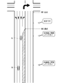
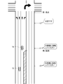
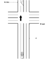
- FIGS. 22 to 24 are diagrams for explaining the base technology, and show a case where the number of lanes dedicated to right turns is increasing at intersections. It is assumed that the host vehicle 16 is traveling in accordance with the guidance of a route that makes a right turn at the intersection that is the first base point.
- the distance of the right turn-only lane is different in each figure, but the timings t0, t1, and t2 for guiding the driver to change lanes are the same in each figure. That is, in the base technology, guidance of lane change is performed at the same timing regardless of whether or not the number of lanes on the road is increasing at the intersection.
- the driver is instructed by voice "Please move to the right lane".
- the driver is instructed by voice to "move to the right lane".
- the vehicle is guided to the right-turn-only lane at a timing that facilitates lane change.
- the timing of the guidance is too early, and the lane cannot be changed to the right turn lane at the timing. In the example of FIG. 24, the guidance timing is too late.
- FIG. 1 is a block diagram illustrating an example of a configuration of a driving support device 1 according to Embodiment 1 of the present invention.
- the driving support device 1 is installed in the host vehicle.
- the driving support device 1 includes a map information acquisition unit 2, a vehicle traveling position recognition unit 3, a route calculation unit 4, a lane guidance information generation unit 5, and a notification control unit 6. ing.
- the map information acquisition unit 2 acquires map information including the number of lanes on a road, the point at which the number of lanes changes, and the traffic regulation for each lane at an intersection.
- the own vehicle traveling position recognition unit 3 recognizes the own vehicle traveling position including the current traveling lane and position of the own vehicle based on the map information acquired by the map information acquiring unit 2.
- the route calculation unit 4 calculates the route of the own vehicle at the intersection.
- the lane guidance information generation unit 5 is configured to provide the information to the intersection based on the map information acquired by the map information acquisition unit 2, the own vehicle travel position recognized by the own vehicle travel position recognition unit 3, and the route calculated by the route calculation unit 4.
- the lane guidance information including the timing and the contents of the lane change guidance before entering is generated.
- the lane guidance information generation unit 5 includes the route calculated by the route calculation unit 4, the route regulation acquired by the map information acquisition unit 2, and the distance and time from the own vehicle traveling position to the first base point which is the intersection.
- Lane guidance information is generated based on at least one of at least one of the distance and the time from the own vehicle traveling position to the second base point where the number of lanes changes from the own vehicle traveling position. That is, when the host vehicle travels toward the first base point, the second base point exists upstream of the first base point.
- the notification control unit 6 performs control for notifying the lane guidance information generated by the lane guidance information generation unit 5.
- FIG. 2 is a block diagram showing an example of the configuration of the driving support device 7 according to another configuration.
- the driving support device 7 includes a map information acquisition unit 2, an own vehicle traveling position recognition unit 3, a route calculation unit 4, a lane guidance information generation unit 5, a notification control unit 6, And a vehicle position detecting unit 8.
- the map information acquisition unit 2 is connected to the map database 9.
- the host vehicle position detecting unit 8 is connected to a GNSS (Global Navigation Satellite System) 10 and a vehicle sensor 11.
- the notification control unit 6 is connected to the display device 12 and the audio output device 13.
- the map database 9 is configured by a storage device such as a hard disk drive or a semiconductor memory, and stores map information including the number of lanes on a road, points where the number of lanes changes, and route regulation for each lane at an intersection. .
- the map database 9 may be installed in the own vehicle or may be installed outside the own vehicle. Further, the map database 9 may be provided in the driving support device 7.
- the map information acquiring unit 2 acquires, from the map database 9, map information including the number of lanes of the road, the point at which the number of lanes changes, and the route regulation for each lane at the intersection. Further, the map information is not limited to the above information, and also includes information on the position of the lane constituting the road, and road links necessary for calculating a route from the current position to the destination.
- the own vehicle position detection unit 8 detects the current position of the own vehicle based on the absolute position of the own vehicle obtained from the GNSS 10 and the speed of the own vehicle obtained from the vehicle sensor 11.
- the GNSS 10 acquires the absolute position of the own vehicle from the satellite.
- the vehicle sensor 11 includes a vehicle speed sensor that measures the speed of the host vehicle.
- the vehicle sensor 11 may include an acceleration sensor that measures the acceleration of the host vehicle and a gyro sensor that measures the inclination of the host vehicle.
- the own vehicle position detection unit 8 may detect the current position of the own vehicle with higher accuracy by taking into account the acceleration and inclination of the own vehicle acquired from the vehicle sensor 11.
- the own vehicle traveling position recognition unit 3 determines the current traveling lane and position of the own vehicle. Recognize the running position of the own vehicle, including
- the route calculation unit 4 calculates or estimates the route of the host vehicle at the intersection based on the map information acquired by the map information acquisition unit 2 and the host vehicle traveling position recognized by the host vehicle traveling position recognition unit 3. Specifically, the route calculation unit 4 calculates a route from the current position of the host vehicle to the destination set by the user, and calculates a route at the intersection included in the route and closest to the current position of the host vehicle. Calculate the path of the vehicle. Alternatively, the course calculation unit 4 may determine the traveling direction of the own vehicle based on the accumulated traveling data of the own vehicle, the current position of the own vehicle, the current time, and the like. Estimate the course of the vehicle.
- the lane guidance information generation unit 5 determines an intersection based on the route calculated by the route calculation unit 4, the route regulation at each intersection at the intersection acquired by the map information acquisition unit 2, and the own vehicle traveling position recognized by the own vehicle traveling position recognition unit 3. And / or at least one of the distance and the time from the host vehicle traveling position recognized by the host vehicle traveling position recognition unit 3 to the point where the number of lanes changes. Based on this, lane guidance information including the timing and content of lane change guidance before entering the intersection is generated.
- the position of the intersection is included in the map information acquired by the map information acquisition unit 2.
- the time from the own vehicle traveling position to the intersection is calculated based on the distance from the own vehicle traveling position to the intersection and the speed of the own vehicle.
- the lane guidance information generation unit 5 acquires the speed of the own vehicle detected by the vehicle sensor 11 from the own vehicle position detection unit 8. The same applies to the calculation of the time from the own vehicle traveling position to the point where the number of lanes changes.
- the notification control unit 6 controls the display device 12 and the audio output device 13 to notify the lane guidance information generated by the lane guidance information generation unit 5.
- the display device 12 displays lane guidance information in accordance with an instruction from the notification control unit 6.
- the voice output device 13 outputs the lane guidance information by voice according to the instruction of the notification control unit 6.
- FIG. 3 is a block diagram illustrating an example of a hardware configuration of the driving support device 7. The same applies to the driving support device 1 shown in FIG.
- Each function of the map information acquisition unit 2, the own vehicle traveling position recognition unit 3, the route calculation unit 4, the lane guidance information generation unit 5, the notification control unit 6, and the own vehicle position detection unit 8 in the driving support device 7 is a processing circuit. Is realized by: That is, the driving support device 7 acquires map information, recognizes the traveling position of the own vehicle, calculates a course, generates lane guidance information, performs control for notifying the lane guidance information, and detects the own vehicle position.
- the processing circuit is a processor 14 (also referred to as a central processing unit, a processing unit, an arithmetic unit, a microprocessor, a microcomputer, or a DSP (Digital Signal Processor)) that executes a program stored in the memory 15.
- a processor 14 also referred to as a central processing unit, a processing unit, an arithmetic unit, a microprocessor, a microcomputer, or a DSP (Digital Signal Processor)
- the functions of the map information acquisition unit 2, the own vehicle traveling position recognition unit 3, the route calculation unit 4, the lane guidance information generation unit 5, the notification control unit 6, and the own vehicle position detection unit 8 in the driving support device 7 are software, This is realized by firmware or a combination of software and firmware.
- Software or firmware is described as a program and stored in the memory 15.
- the processing circuit realizes the function of each unit by reading and executing the program stored in the memory 15. That is, the driving support device 7 obtains map information, recognizes the traveling position of the own vehicle, calculates a course, generates lane guidance information, performs control for notifying lane guidance information, It comprises a memory 15 for storing a program that results in the step of detecting the vehicle position being executed.
- the memory is, for example, a nonvolatile (volatile memory) such as a RAM (Random Access Memory), a ROM (Read Only Memory), a flash memory, an EPROM (Erasable Programmable Read Only Memory), and an EEPROM (Electrically Erasable Programmable Read Only Memory).
- a nonvolatile memory such as a RAM (Random Access Memory), a ROM (Read Only Memory), a flash memory, an EPROM (Erasable Programmable Read Only Memory), and an EEPROM (Electrically Erasable Programmable Read Only Memory).
- a semiconductor memory, a magnetic disk, a flexible disk, an optical disk, a compact disk, a mini disk, a DVD, or the like, or any storage medium used in the future may be used.
- FIG. 4 is a flowchart illustrating an example of the operation of the driving support device 7.
- step S101 the map information acquisition unit 2 acquires, from the map database 9, map information including the number of lanes of the road, the point at which the number of lanes changes, and the traffic regulation for each lane at the intersection.
- step S ⁇ b> 102 the own vehicle traveling position recognition unit 3 performs the current traveling of the own vehicle based on the current position of the own vehicle detected by the own vehicle position detection unit 8 and the map information acquired by the map information acquisition unit 2. Recognize the running position of the vehicle including the lane and the position.
- step S ⁇ b> 103 the lane guidance information generation unit 5 determines the own vehicle traveling position recognized by the own vehicle traveling position recognition unit 3 and the position of the intersection included in the map information acquired by the map information acquisition unit 2. It is determined whether the vehicle has reached the intersection. If the own vehicle has reached the intersection, the processing shown in FIG. 4 is ended. On the other hand, if the host vehicle has not reached the intersection, the process proceeds to step S104.
- step S104 the lane guidance information generation unit 5 uses the number of lanes of the road included in the map information acquired by the map information acquisition unit 2 and the right-turn right before the intersection based on the lane regulation for each lane at the intersection. Determine whether the lane is increasing. If the right-turn-only lane has not increased before the intersection, the processing illustrated in FIG. 4 ends. On the other hand, if the right-turn-only lane is increasing just before the intersection, the process proceeds to step S105.
- step S ⁇ b> 105 the lane guidance information generation unit 5 determines whether or not the vehicle turns right at an intersection based on the route calculated by the route calculation unit 4. If the host vehicle does not make a right turn at the intersection, the processing shown in FIG. 4 ends. On the other hand, when the vehicle turns right at the intersection, the process proceeds to step S106.
- the lane guidance information generation unit 5 includes the current travel lane of the own vehicle included in the own vehicle travel position recognized by the own vehicle travel position recognition unit 3 and the map information acquired by the map information acquisition unit 2. Is calculated based on the number of lanes of the road and the lane regulation for each lane at the intersection, the number of lanes for which the host vehicle should change lanes from the current traveling lane to the lane corresponding to the lane. Specifically, the lane guidance information generation unit 5 calculates the number of lanes that must be changed between the lane in which the host vehicle is traveling and the lane dedicated to right turn.
- step S107 based on the number of lanes calculated in step S106, the lane guidance information generation unit 5 determines whether the vehicle needs to change lanes. When the lane change of the own vehicle is necessary, the process proceeds to step S108. On the other hand, when it is not necessary to change the lane of the own vehicle, the process proceeds to step S113.
- the lane guidance information generation unit 5 includes the current position of the own vehicle included in the own vehicle travel position recognized by the own vehicle travel position recognition unit 3 and the current position of the own vehicle included in the map information acquired by the map information acquisition unit 2. Based on the position of the intersection and the point where the number of lanes changes, it is determined whether or not there is a point between the host vehicle and the intersection where the number of lanes dedicated to right turns is increasing. Here, the point where the number of lanes changes corresponds to the point where the number of lanes dedicated to right turns is increasing. If there is a point where the number of lanes dedicated to right turn is increasing between the own vehicle and the intersection, the process proceeds to step S109. On the other hand, if there is no point where the number of lanes dedicated to right turn is increasing between the own vehicle and the intersection, the process proceeds to step S113.
- the lane guidance information generation unit 5 calculates at least one of the distance and the time from the host vehicle to the point where the right turn dedicated lane is increasing. Specifically, the lane guidance information generation unit 5 compares the current position of the own vehicle included in the own vehicle travel position recognized by the own vehicle travel position recognition unit 3 with the map information acquired by the map information acquisition unit 2. The distance from the own vehicle to the point where the right-turn-only lane is increasing is calculated based on the point where the number of the included lanes changes.
- the lane guidance information generation unit 5 outputs a right turn only signal from the own vehicle based on the distance from the own vehicle to the point where the right turn dedicated lane is increasing and the speed of the own vehicle detected by the own vehicle position detection unit 8. Calculate the time required to reach the point where the lane is increasing.
- step S110 the lane guidance information generation unit 5 needs to change the lane to the right lane based on at least one of the distance and the time from the host vehicle calculated in step S109 to the point where the right turn dedicated lane is increasing.
- the timing of notifying the user of the presence is calculated.
- the lane guidance information generation unit 5 generates the content of the lane change guidance. That is, the lane guidance information generation unit 5 generates lane guidance information including the timing and content of the lane change guidance before entering the difference point.
- step S111 the lane guidance information generation unit 5 determines whether or not it is the timing calculated in step S110. If it is the timing calculated in step S110, the process proceeds to step S112. On the other hand, if it is not the timing calculated in step S110, the process returns to step S109.
- step S112 the notification control unit 6 notifies the user that it is necessary to change lanes to the right lane. Specifically, based on the lane guidance information generated by the lane guidance information generation unit 5 in step S110, the notification control unit 6 notifies the display device 12 and the voice output device 13 that the lane needs to be changed to the right lane. The user is notified from at least one of them. Then, the process returns to step S106.
- the lane guidance information generation unit 5 calculates at least one of the distance and the time from the vehicle to the intersection. Specifically, the lane guidance information generation unit 5 compares the current position of the own vehicle included in the own vehicle travel position recognized by the own vehicle travel position recognition unit 3 with the map information acquired by the map information acquisition unit 2. The distance from the host vehicle to the intersection is calculated based on the included position of the intersection. The lane guidance information generation unit 5 calculates the time required for the vehicle to reach the intersection based on the distance from the vehicle to the intersection and the speed of the vehicle detected by the vehicle position detection unit 8. I do.
- step S114 the lane guidance information generation unit 5 determines the timing of notifying the user that it is necessary to make a right turn at the intersection based on at least one of the distance from the vehicle to the intersection and the time calculated in step S113. calculate. In addition, the lane guidance information generation unit 5 generates the content of the right turn guidance. That is, the lane guidance information generation unit 5 generates lane guidance information including the timing and content of right turn guidance before entering the difference point.
- step S115 the lane guidance information generation unit 5 determines whether or not the timing calculated in step S114 is reached. If it is the timing calculated in step S114, the process proceeds to step S116. On the other hand, if it is not the timing calculated in step S114, the process returns to step S113.
- step S116 the notification control unit 6 notifies the user that it is necessary to make a right turn. Specifically, based on the lane guidance information generated by the lane guidance information generation unit 5 in step S114, the notification control unit 6 indicates at least one of the display device 12 and the audio output device 13 that a right turn is required. To notify the user. Thereafter, the processing illustrated in FIG. 4 ends.
- Example> 5 to 7 are diagrams showing an example of the operation of the driving support device 7.
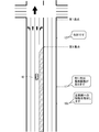
- the host vehicle 16 is traveling on a road having a plurality of lanes on one side toward an intersection in front. Right before the intersection, the right-turn lanes are increasing, and the other lanes are straight-ahead lanes or left-turn lanes.
- the first base point corresponds to an intersection.
- the second base point corresponds to a point where the number of lanes dedicated to right turns increases.
- the route calculation unit 4 of the driving support device 7 calculates a route where the vehicle 16 turns right at the intersection.
- the host vehicle 16 is traveling in the second lane from the left of the road. Then, at the timing t0, the notification control unit 6 controls the voice output device 13 to output a voice "Please move to the right lane".
- the notification control unit 6 may control the display device 12 to display characters, graphics, or a combination thereof indicating movement to the right lane.
- the timing t0 corresponds to the timing calculated by the lane guidance information generation unit 5 in step S110 of FIG. Specifically, the lane guidance information generation unit 5 notifies the user of the necessity of changing lanes to the right lane based on at least one of the distance from the host vehicle to the second base point and the time. Is calculated.
- the timing t0 may be a point just before the second base point by a predetermined distance, for example, a point 500 m before.
- the further preceding point may be set as the timing t0, and when the speed of the own vehicle 16 is lower than the predetermined threshold value. May be a point a little further ahead as the timing t0.
- the point before this point may be set as timing t0, and the time required to reach the second base point is determined in advance. If the time is longer than the predetermined time, a point slightly earlier may be set as the timing t0.
- a predetermined time until reaching the second base point may be set as the timing t0.
- a point before this point may be set as timing t0, and when the distance or time from the host vehicle to the first base point is longer than the threshold value, the timing is a little more.
- the previous point may be the timing t0.
- the driver performs driving to change the lane of the vehicle 16 to the right lane.
- the notification control unit 6 controls the audio output device 13 to output an audio signal “Please move to the right lane”.
- the notification control unit 6 may control the display device 12 to display characters, graphics, or a combination thereof indicating movement to the right lane.
- the timing t1 corresponds to the timing calculated by the lane guidance information generation unit 5 in step S110 of FIG. Specifically, the lane guidance information generation unit 5 notifies the user of the need to change lanes to the right lane based on at least one of the distance and the time from the host vehicle to the second base point. Is calculated.
- the timing t1 is a point located a predetermined distance before the second base point. At this point, as in the calculation of the timing t0, the time to reach the second base point may be considered, and at least one of the distance to the first base point and the time may be considered.
- timing t1 is a point at which the host vehicle 16 has passed the second base point.
- the point at which the host vehicle 16 has passed the second base point may be set as the timing t1.
- the timing t1 may be calculated according to the distance between the first base point and the second base point.
- the notification control unit 6 controls the sound output device 13 to output a sound “turn right”. Note that the notification control unit 6 may control the display device 12 to display a character indicating a right turn, a graphic, or a combination thereof.
- the driver performs a driving to turn the host vehicle 16 right at the intersection.
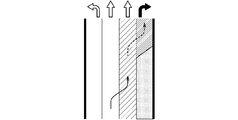
- ⁇ Display example> 8 to 13 are views showing an example of the display of the lane change, and show the margin before turning right at the intersection.
- the dashed arrow indicates that the lane should be changed to the right turn lane.
- the hatched portion indicates the position of the host vehicle on the upstream side of the point where the number of lanes changes, that is, on the upstream side of the second base point shown in FIGS. 5 to 7, and the host vehicle moves in the order of FIGS. This indicates that the vehicle is approaching the second base point.
- the hatched portion may be, for example, blue.
- the hatched portion may be yellow, for example.
- the hatched portion since the host vehicle is quite close to the second base point and there is no room, the hatched portion may be, for example, red.
- the solid arrow indicates that the lane should be changed to the right lane at the timing t0 shown in FIGS. 5 to 7, for example.
- the dashed arrow indicates that the lane should be changed to a right turn lane, for example, at timing t1 shown in FIGS. That is, the dashed arrow indicates a future lane change.
- 11, 12, and 13 show that the own vehicle is approaching the intersection.
- FIG. 11 shows that the lane can be changed to the right lane or the right turn lane because there is enough distance between the host vehicle and the intersection.
- FIG. 12 shows that the own vehicle is closer than in FIG. 11 and should move to the right lane within 2 seconds, for example.
- FIG. 13 shows that it is difficult to make a right turn at an intersection even if the vehicle changes lanes to the right lane now because the host vehicle is so close to the intersection that there is no room.
- the timing of the lane change is set based on the point where the number of lanes changes. Calculated. Therefore, it is possible to guide the user to change lanes at an appropriate timing.
- the present invention is not limited to this.
- the timing t0 may be calculated based on the first base point. That is, when the host vehicle 16 travels toward the first base point, the second base point is located downstream of the first base point.
- the voice output or display "Please move to the left lane" is displayed. The driver can change lanes with a margin before passing through the intersection without having to change lanes in a rush after passing through the intersection.
- the lane guidance information generating unit 5 may generate lane guidance information indicating that the number of lanes changes.
- the timing of notifying the user of the change in the number of lanes may be, for example, before the timing t0 shown in FIG.
- the present invention is not limited to this.
- the same effect can be obtained even when the number of lanes dedicated to left turns increases at an intersection and the vehicle turns left at the intersection.
- FIG. 15 is a diagram illustrating an example of the operation of the driving support device 7.
- the host vehicle 16 is traveling on a road having a plurality of lanes on one side toward an intersection in front.
- the right turn lane is increasing.
- the lanes that can be turned right at the intersection are the right-turn-only lane and the straight-on and right-turn-only lanes existing to the left of the right-turn only lane.
- the first base point corresponds to an intersection.
- the second base point corresponds to a point where the number of lanes dedicated to right turns increases.
- the route calculation unit 4 of the driving support device 7 calculates a route where the vehicle 16 turns right at the intersection.
- the host vehicle 16 is traveling in the second lane from the left of the road. Then, at the timing t0a, the notification control unit 6 controls the audio output device 13 to output an audio signal “Please move to the right lane”.
- the notification control unit 6 may control the display device 12 to display characters, graphics, or a combination thereof indicating movement to the right lane.
- the timing t0a corresponds to the timing calculated by the lane guidance information generation unit 5 in step S110 of FIG. Specifically, the lane guidance information generation unit 5 determines whether the vehicle 16 has at least one of the distance and the time from the own vehicle to the second base point and the lane between the own vehicle 16 and the lane corresponding to the course. Based on the number of lanes to be changed, a timing t0a for notifying the user that the lane needs to be changed to the right lane is calculated.
- the timing t0a is calculated by the same method as the timing t0 described in FIGS. 5 to 7 of the first embodiment, but differs from the timing t0 in that the number of lanes to be changed is taken into account. In the example of FIG. 15, the number of lanes to be changed by the host vehicle 16 is “1”. That is, it is possible to make a right turn at an intersection by moving to the right lane only once.
- the timing t0a is delayed as the number of lanes to be changed is smaller.
- the number of lanes for which the host vehicle 16 should change lanes is “2”. Therefore, the timing of guiding the lane change at the timing t0a shown in FIG. 15 is later than the timing t0 shown at FIGS.
- the timing and content of notifying the lane change guidance are determined according to the number of lanes to be changed. Therefore, it is possible to guide the user to change lanes at an appropriate timing.
- the timing and the content of the guidance for the lane change are different between when it is necessary to change lanes to an increasing lane at an intersection and when it is not necessary to change lanes to an increasing lane at an intersection. It is characterized by the following.
- the configuration and operation of the driving support device according to the third embodiment are the same as those in the second embodiment, and thus detailed description is omitted here.
- the driving assistance device according to the third embodiment will be described as being the driving assistance device 7 shown in FIG.
- the driving support device according to the third embodiment performs the operation shown in FIG.
- FIG. 16 is a diagram showing an example of the operation of the driving support device 7.
- the host vehicle 16 is traveling on a road having a plurality of lanes on one side toward an intersection in front. Right before the intersection, the right turn lane is increasing. The right-turn lane is the only lane that can be turned right at the intersection.
- the first base point corresponds to an intersection.
- the second base point corresponds to a point where the number of lanes dedicated to right turns increases.
- the route calculation unit 4 of the driving support device 7 calculates a route where the vehicle 16 turns right at the intersection.
- the own vehicle 16 is traveling on the third lane from the left of the road. Then, at the timing t0b, the notification control unit 6 controls the sound output device 13 to output a sound such as "Branch soon. Please move to the right lane".
- the notification control unit 6 may control the display device 12 to display characters, graphics, or a combination thereof indicating movement to the right lane.
- the timing t0b corresponds to the timing calculated by the lane guidance information generation unit 5 in step S110 of FIG. Specifically, the lane guidance information generation unit 5 determines whether the vehicle 16 has at least one of the distance and the time from the own vehicle to the second base point and the lane between the own vehicle 16 and the lane corresponding to the course. Based on the number of lanes to be changed, a timing t0b for notifying the user that the lane needs to be changed to the right lane is calculated.
- the timing t0b is calculated by the same method as the timing t0a described in the second embodiment with reference to FIG. In the example of FIG. 16, the number of lanes to be changed by the host vehicle 16 is “1”. That is, it is possible to make a right turn at an intersection by moving to the right lane only once. In this case, guidance of lane change is provided at timing t0.
- FIG. 17 is a diagram showing an example of the operation of the driving support device 7.
- the host vehicle 16 is traveling on a road having a plurality of lanes on one side toward an intersection in front.
- the right turn lane is increasing.
- the lanes that can be turned right at the intersection are the right-turn-only lane and the straight-on and right-turn-only lanes existing to the left of the right-turn only lane.
- the first base point corresponds to an intersection.
- the second base point corresponds to a point where the number of lanes dedicated to right turns increases.
- the route calculation unit 4 of the driving support device 7 calculates a route where the vehicle 16 turns right at the intersection.
- the host vehicle 16 is traveling on the third lane from the left of the road. In this case, the host vehicle 16 can make a right turn at the intersection if the vehicle 16 continues to travel in the current lane. That is, the host vehicle 16 can make a right turn at the intersection without changing lanes. Therefore, the notification control unit 6 does not guide the lane change.
- the notification control unit 6 may notify that there is no need to change lanes, for example, at timing t0b shown in FIG.
- the configuration of the driving support device according to the fourth embodiment is the same as that of the first embodiment, and a detailed description is omitted here.
- the driving support device 7 according to the fourth embodiment will be described as the driving support device 7 illustrated in FIG.
- FIG. 18 is a flowchart showing an example of the operation of the driving support device 7.
- step S201 the map information acquisition unit 2 acquires, from the map database 9, map information including the number of lanes of the road, the point at which the number of lanes changes, and the traffic regulation for each lane at the intersection.
- step S ⁇ b> 202 the own vehicle traveling position recognition unit 3 performs the current traveling of the own vehicle based on the current position of the own vehicle detected by the own vehicle position detecting unit 8 and the map information acquired by the map information acquiring unit 2. Recognize the running position of the vehicle including the lane and the position.
- step S ⁇ b> 203 the lane guidance information generation unit 5 is configured to calculate the vehicle traveling position based on the own vehicle traveling position recognized by the own vehicle traveling position recognition unit 3 and the position of the intersection included in the map information acquired by the map information acquisition unit 2. It is determined whether the vehicle has reached the intersection. If the own vehicle has reached the intersection, the processing shown in FIG. 18 is ended. On the other hand, when the own vehicle has not reached the intersection, the process proceeds to step S204.
- step S204 the lane guidance information generation unit 5 uses the number of lanes of the road included in the map information acquired by the map information acquisition unit 2 and the right-turn right before the intersection on the basis of the lane regulation for each lane at the intersection. Determine whether the lane is increasing. If the right-turn-only lane has not increased before the intersection, the processing illustrated in FIG. 18 ends. On the other hand, if the right-turn-only lane is increasing just before the intersection, the process proceeds to step S205.
- step S ⁇ b> 205 the lane guidance information generation unit 5 determines whether or not the vehicle travels straight at the intersection based on the route calculated by the route calculation unit 4. If the host vehicle does not go straight on the intersection, the processing shown in FIG. 18 ends. On the other hand, when the own vehicle goes straight ahead at the intersection, the process proceeds to step S206.
- step S ⁇ b> 206 the lane guidance information generation unit 5 includes the current travel lane of the own vehicle included in the own vehicle travel position recognized by the own vehicle travel position recognition unit 3 and the map information acquired by the map information acquisition unit 2. It is determined whether or not the route regulation at the intersection of the current traveling lane is exclusively for straight ahead, based on the route regulation for each lane at the intersection included in (1). If the route regulation at the intersection of the current lane is exclusive for straight ahead, the process proceeds to step S207. On the other hand, when the course regulation at the intersection of the current driving lane is not exclusive for straight ahead, the processing shown in FIG. 18 ends.
- the lane guidance information generation unit 5 includes the current position of the own vehicle included in the own vehicle travel position recognized by the own vehicle travel position recognition unit 3 and the current position of the own vehicle included in the map information acquired by the map information acquisition unit 2. It is determined whether or not the vehicle is traveling in the rightmost lane before the point where the number of lanes dedicated to right turns is increasing, based on the point at which the number of lanes changing is changed. That is, the lane guidance information generation unit 5 determines whether or not the own vehicle is traveling in a lane located before the point where the right turn dedicated lane is increasing and to the left of the right turn dedicated lane. If the host vehicle is traveling in the rightmost lane before the point where the right turn dedicated lane is increasing, the process proceeds to step S208. On the other hand, when the host vehicle is not traveling in the rightmost lane before the point where the right turn dedicated lane is increasing, the processing shown in FIG. 18 is ended.
- step S208 the lane guidance information generation unit 5 determines the current travel lane of the own vehicle included in the own vehicle travel position recognized by the own vehicle travel position recognition unit 3 and the map information acquired by the map information acquisition unit 2. It is determined whether or not the left lane existing to the left of the current traveling lane of the own vehicle can go straight through the intersection, based on the lane-by-lane route regulation at the intersection included in . If the left lane can travel straight at the intersection, the process proceeds to step S209. On the other hand, if it is not possible for the left lane to go straight on the intersection, the processing shown in FIG. 18 ends.
- the lane guidance information generation unit 5 calculates at least one of the distance and the time from the host vehicle to the point where the right turn dedicated lane is increasing. Specifically, the lane guidance information generation unit 5 compares the current position of the own vehicle included in the own vehicle travel position recognized by the own vehicle travel position recognition unit 3 with the map information acquired by the map information acquisition unit 2. The distance from the own vehicle to the point where the right-turn-only lane is increasing is calculated based on the point where the number of the included lanes changes. Further, the lane guidance information generation unit 5 outputs a right turn only signal from the own vehicle based on the distance from the own vehicle to the point where the right turn dedicated lane is increasing and the speed of the own vehicle detected by the own vehicle position detection unit 8. Calculate the time required to reach the point where the lane is increasing.
- step S210 the lane guidance information generation unit 5 performs lane change to the left lane based on at least one of the distance and the time from the host vehicle calculated in step S209 to the point where the right turn dedicated lane is increasing.
- the timing for notifying the user of the recommendation is calculated.
- the lane guidance information generation unit 5 generates the content of the lane change guidance. That is, the lane guidance information generation unit 5 generates lane guidance information including the timing and content of the lane change guidance before entering the difference point.
- step S211 the lane guidance information generation unit 5 determines whether or not it is the timing calculated in step S210. If it is the timing calculated in step S210, the process proceeds to step S212. On the other hand, if it is not the timing calculated in step S210, the process returns to step S208.
- step S212 the notification control unit 6 notifies the user that lane change to the left lane is recommended. Specifically, based on the lane guidance information generated by the lane guidance information generation unit 5 in step S210, the notification control unit 6 notifies the display device 12 and the audio output device 13 that lane change to the left lane is recommended. The user is notified from at least one of them. Thereafter, the processing illustrated in FIG. 18 ends.
- FIG. 19 is a diagram illustrating an example of an operation of the driving support device 7.
- the host vehicle 16 is traveling on a road having a plurality of lanes on one side toward an intersection in front.
- the host vehicle 16 is traveling in a lane corresponding to a straight-only lane at the intersection.
- the right turn lane is increasing.
- the right-turn lane is the only lane that can be turned right at the intersection.
- the first base point corresponds to an intersection.
- the second base point corresponds to a point where the number of lanes dedicated to right turns increases.
- the course calculation unit 4 of the driving support device 7 calculates a course in which the host vehicle 16 travels straight through the intersection.
- the host vehicle 16 is traveling in the third lane from the left of the road. In this case, if the vehicle travels toward the intersection as it is, it may be affected by traffic congestion of other vehicles extending from the right turn lane. Therefore, in the fourth embodiment, at the timing t0c, the notification control unit 6 controls the sound output device 13 to output a sound saying “we recommend moving to the left lane”.
- the notification control unit 6 may control the display device 12 to display characters, graphics, or a combination thereof indicating movement to the right lane.
- the host vehicle 16 changes lanes to the lane on the left side in response to such a lane change guidance, so that the influence of traffic congestion caused by other vehicles extending from the right turn lane can be avoided.
- the timing t0c corresponds to the timing calculated by the lane guidance information generation unit 5 in step S210 in FIG. Specifically, the lane guidance information generation unit 5 notifies the user of recommending the lane change to the left lane based on at least one of the distance from the host vehicle to the second base point and the time. Is calculated.
- the timing t0c is calculated in the same manner as the timing t0 described in the first embodiment with reference to FIG.
- the notification control unit 6 may control the voice output device 13 to output a voice saying “there is a right turn lane on the right”.
- the notification control unit 6 may control the display device 12 to display a character, a graphic, or a combination thereof indicating that there is a right-turn-only lane.
- the timing t1 is calculated in the same manner as the timing t0c.
- the timing t0c may be changed according to the distance between the first base point and the second base point. For example, the shorter the distance between the first base point and the second base point, the earlier the timing t0c may be.
- the lane guidance information generation unit 5 When the traffic congestion travel time for each lane can be obtained by VICS (Vehicle Information and Communication System) or the like, the lane guidance information generation unit 5 generates the lane guidance information in consideration of the traffic congestion travel time. You may.
- the traffic congestion travel time refers to the time required to pass a certain distance. For example, if the lane guidance information generation unit 5 determines that the right-turn-only lane is not congested based on the traffic congestion travel time, the lane guidance information generation unit 5 may not perform the guidance for changing lanes to the left lane.
- the lane guidance information generation unit 5 may determine the timings t0c and t1 according to the traffic jam travel time.
- FIG. 20 is a diagram illustrating an example of the operation of the driving support device 7.
- the own vehicle 16 is traveling on a road having a plurality of lanes on one side toward an intersection in front.
- the host vehicle 16 is traveling in a lane corresponding to a straight-ahead and a right-turnable lane at an intersection.
- the right turn lane is increasing.
- the lanes that can be turned right at the intersection are the right-turn-only lane and the straight-on and right-turn-only lanes existing to the left of the right-turn only lane.
- the first base point corresponds to an intersection.
- the second base point corresponds to a point where the number of lanes dedicated to right turns increases.
- the course calculation unit 4 of the driving support device 7 calculates a course in which the host vehicle 16 travels straight through the intersection.
- the host vehicle 16 is traveling on the third lane from the left of the road. At the intersection, there are two lanes that can be turned right. In such a case, there is a low possibility that another vehicle will be congested in the right turn lane and the right turn lane adjacent to the left turn lane. Therefore, the notification control unit 6 may control the voice output device 13 so as to output a voice message “running in a straight-ahead and right-turnable lane” at the timing t1 without guiding the lane change. Note that the notification control unit 6 may control the display device 12 to display a character, a graphic, or a combination thereof indicating that the vehicle is traveling in a straight lane and a right turn lane. The timing t1 is calculated in the same manner as the timing t0c.
- the fourth embodiment when the right-turn-only lane is increasing at the intersection, it is determined that there is a high possibility of congestion, and the vehicle traveling straight at the intersection can go straight at the intersection. It is recommended to change lanes to the left lane. As a result, the own vehicle can avoid the influence of traffic congestion caused by another vehicle extending from the right turn dedicated lane. In addition, when there are a plurality of lanes that can make a right turn at an intersection, it is determined that there is a low possibility of congestion, and no lane change guidance is given to the vehicle traveling straight through the intersection. Thus, it is possible to guide the user to change lanes at an appropriate timing.
- the driving support device described above is not only a vehicle-mounted navigation device, that is, a car navigation device, but also a PND (Portable Navigation Device) that can be mounted on a vehicle, a server provided outside the vehicle, and the like, and appropriately combined as a system.
- the present invention can be applied to a navigation device to be constructed or a device other than the navigation device. In this case, each function or each component of the driving support device is distributed and arranged for each function constituting the system.
- the function of the driving support device can be arranged in the server.
- the user side includes a GNSS 10, a vehicle sensor 11, a display device 12, and an audio output device 13.
- the server 17 includes a map information acquisition unit 2, an own vehicle traveling position recognition unit 3, a route calculation unit 4, a lane guidance information generation unit 5, a notification control unit 6, and an own vehicle position detection unit 8.
- the software for executing the operations in the above embodiments may be incorporated in, for example, a server.
- the driving assistance method realized by executing this software by the server acquires the map information including the number of lanes of the road, the point at which the number of lanes changes, and the route regulation for each lane at the intersection, and obtains the current Recognize the own vehicle traveling position including the traveling lane and position, calculate the path of the own vehicle at the intersection, and based on the acquired map information, the recognized own vehicle traveling position, and the calculated path, before entering the intersection.
- Generating lane guidance information including the timing and content of lane change guidance, performing control for notifying the generated lane guidance information, and generating lane guidance information are based on the calculated route, the acquired route regulation, and the own vehicle traveling.
- the embodiments can be freely combined, or the embodiments can be appropriately modified or omitted within the scope of the invention.
- 1 driving assistance device 2 map information acquisition unit, 3 own vehicle traveling position recognition unit, 4 track calculation unit, 5 lane guidance information generation unit, 6 notification control unit, 7 driving assistance device, 8 own vehicle position detection unit, 9 map Database, 10 GNSS, 11 vehicle sensor, 12 display device, 13 audio output device, 14 processor, 15 memory, 16 vehicle.
Landscapes
- Engineering & Computer Science (AREA)
- Radar, Positioning & Navigation (AREA)
- Remote Sensing (AREA)
- Automation & Control Theory (AREA)
- Physics & Mathematics (AREA)
- General Physics & Mathematics (AREA)
- Navigation (AREA)
Abstract
L'objectif de la présente invention est de fournir un dispositif d'aide à la conduite et un procédé d'aide à la conduite permettant de fournir un guidage concernant des changements de voie au moment approprié. Le dispositif d'aide à la conduite de la présente invention comprend : une unité d'acquisition d'informations cartographiques qui acquiert des informations cartographiques comprenant le nombre de voies sur une route, des emplacements où le nombre de voies change et des restrictions d'itinéraire pour chaque voie au niveau d'une intersection ; une unité de reconnaissance d'emplacement de déplacement de véhicule hôte qui reconnaît l'emplacement de déplacement d'un véhicule hôte ; une unité de calcul d'itinéraire qui calcule un itinéraire pour le véhicule hôte au niveau de l'intersection ; une unité de génération d'informations de guidage de voie qui, en fonction des informations cartographiques, de l'itinéraire et de l'emplacement de déplacement du véhicule hôte, génère des informations de guidage de voie contenant un contenu et une synchronisation d'un guidage concernant des changements de voie avant l'entrée dans l'intersection ; et une unité de commande de notification qui commande la notification des informations de guidage de voie. L'unité de génération d'informations de guidage de voie génère les informations de guidage de voie en fonction : de l'itinéraire ; des restrictions d'itinéraire ; et du temps et de la distance de l'emplacement de déplacement du véhicule hôte à un premier point de base et/ou du temps et de la distance de l'emplacement de déplacement du véhicule hôte à un second point de base.
Priority Applications (2)
| Application Number | Priority Date | Filing Date | Title |
|---|---|---|---|
| PCT/JP2018/024330 WO2020003396A1 (fr) | 2018-06-27 | 2018-06-27 | Dispositif et procédé d'aide à la conduite |
| JP2020526767A JP7065959B2 (ja) | 2018-06-27 | 2018-06-27 | 運転支援装置および運転支援方法 |
Applications Claiming Priority (1)
| Application Number | Priority Date | Filing Date | Title |
|---|---|---|---|
| PCT/JP2018/024330 WO2020003396A1 (fr) | 2018-06-27 | 2018-06-27 | Dispositif et procédé d'aide à la conduite |
Publications (1)
| Publication Number | Publication Date |
|---|---|
| WO2020003396A1 true WO2020003396A1 (fr) | 2020-01-02 |
Family
ID=68986676
Family Applications (1)
| Application Number | Title | Priority Date | Filing Date |
|---|---|---|---|
| PCT/JP2018/024330 Ceased WO2020003396A1 (fr) | 2018-06-27 | 2018-06-27 | Dispositif et procédé d'aide à la conduite |
Country Status (2)
| Country | Link |
|---|---|
| JP (1) | JP7065959B2 (fr) |
| WO (1) | WO2020003396A1 (fr) |
Cited By (5)
| Publication number | Priority date | Publication date | Assignee | Title |
|---|---|---|---|---|
| JP2021170292A (ja) * | 2020-04-17 | 2021-10-28 | トヨタ自動車株式会社 | 車両制御装置 |
| CN113744539A (zh) * | 2021-09-17 | 2021-12-03 | 合肥工业大学 | 一种基于渗透率的网联车专用车道动态调控方法 |
| CN114646326A (zh) * | 2020-12-18 | 2022-06-21 | 阿里巴巴集团控股有限公司 | 导航方法、设备、计算机存储介质及计算机程序产品 |
| JP2023515188A (ja) * | 2020-02-28 | 2023-04-12 | 華為技術有限公司 | ナビゲーション方法および装置 |
| CN116257597A (zh) * | 2021-12-10 | 2023-06-13 | 腾讯科技(深圳)有限公司 | 车道指示方法、装置、设备、存储介质及计算机程序产品 |
Families Citing this family (1)
| Publication number | Priority date | Publication date | Assignee | Title |
|---|---|---|---|---|
| CN113850994B (zh) * | 2021-09-09 | 2022-12-30 | 安徽科力信息产业有限责任公司 | 一种道路信息展示与变更方法及系统 |
Citations (5)
| Publication number | Priority date | Publication date | Assignee | Title |
|---|---|---|---|---|
| JP2003240581A (ja) * | 2003-01-14 | 2003-08-27 | Aisin Aw Co Ltd | ナビゲーション装置及び該装置の記録媒体 |
| JP2014115231A (ja) * | 2012-12-11 | 2014-06-26 | Alpine Electronics Inc | 車載ナビゲーション装置 |
| JP2017032438A (ja) * | 2015-08-03 | 2017-02-09 | アイシン・エィ・ダブリュ株式会社 | 推奨レーン決定システム、方法およびプログラム |
| JP2017053678A (ja) * | 2015-09-08 | 2017-03-16 | アイシン・エィ・ダブリュ株式会社 | 走行支援システム、走行支援方法及びコンピュータプログラム |
| JP2017173261A (ja) * | 2016-03-25 | 2017-09-28 | パイオニア株式会社 | 表示制御装置及び表示制御方法並びに表示制御用プログラム及び記録媒体 |
-
2018
- 2018-06-27 WO PCT/JP2018/024330 patent/WO2020003396A1/fr not_active Ceased
- 2018-06-27 JP JP2020526767A patent/JP7065959B2/ja active Active
Patent Citations (5)
| Publication number | Priority date | Publication date | Assignee | Title |
|---|---|---|---|---|
| JP2003240581A (ja) * | 2003-01-14 | 2003-08-27 | Aisin Aw Co Ltd | ナビゲーション装置及び該装置の記録媒体 |
| JP2014115231A (ja) * | 2012-12-11 | 2014-06-26 | Alpine Electronics Inc | 車載ナビゲーション装置 |
| JP2017032438A (ja) * | 2015-08-03 | 2017-02-09 | アイシン・エィ・ダブリュ株式会社 | 推奨レーン決定システム、方法およびプログラム |
| JP2017053678A (ja) * | 2015-09-08 | 2017-03-16 | アイシン・エィ・ダブリュ株式会社 | 走行支援システム、走行支援方法及びコンピュータプログラム |
| JP2017173261A (ja) * | 2016-03-25 | 2017-09-28 | パイオニア株式会社 | 表示制御装置及び表示制御方法並びに表示制御用プログラム及び記録媒体 |
Cited By (9)
| Publication number | Priority date | Publication date | Assignee | Title |
|---|---|---|---|---|
| JP2023515188A (ja) * | 2020-02-28 | 2023-04-12 | 華為技術有限公司 | ナビゲーション方法および装置 |
| JP7459276B2 (ja) | 2020-02-28 | 2024-04-01 | 華為技術有限公司 | ナビゲーション方法および装置 |
| JP2021170292A (ja) * | 2020-04-17 | 2021-10-28 | トヨタ自動車株式会社 | 車両制御装置 |
| JP7200970B2 (ja) | 2020-04-17 | 2023-01-10 | トヨタ自動車株式会社 | 車両制御装置 |
| US11685379B2 (en) | 2020-04-17 | 2023-06-27 | Toyota Jidosha Kabushiki Kaisha | Vehicle control device and storage medium storing computer program for vehicle control |
| CN114646326A (zh) * | 2020-12-18 | 2022-06-21 | 阿里巴巴集团控股有限公司 | 导航方法、设备、计算机存储介质及计算机程序产品 |
| CN113744539A (zh) * | 2021-09-17 | 2021-12-03 | 合肥工业大学 | 一种基于渗透率的网联车专用车道动态调控方法 |
| CN113744539B (zh) * | 2021-09-17 | 2022-05-10 | 合肥工业大学 | 一种基于渗透率的网联车专用车道动态调控方法 |
| CN116257597A (zh) * | 2021-12-10 | 2023-06-13 | 腾讯科技(深圳)有限公司 | 车道指示方法、装置、设备、存储介质及计算机程序产品 |
Also Published As
| Publication number | Publication date |
|---|---|
| JP7065959B2 (ja) | 2022-05-12 |
| JPWO2020003396A1 (ja) | 2021-06-03 |
Similar Documents
| Publication | Publication Date | Title |
|---|---|---|
| JP7065959B2 (ja) | 運転支援装置および運転支援方法 | |
| JP4466238B2 (ja) | 車両用ナビゲーション装置 | |
| EP2056070B1 (fr) | Appareil et programme de navigation de véhicule | |
| JP6036371B2 (ja) | 車両用運転支援システム及び運転支援方法 | |
| US8868334B2 (en) | Moving body position detection system, moving body position detection apparatus, moving body position detection method, and computer-readable storage medium | |
| JP5479398B2 (ja) | 運転支援装置、運転支援方法及びコンピュータプログラム | |
| JP2009047491A (ja) | ナビゲーション装置 | |
| JP6307853B2 (ja) | 車線変更支援装置 | |
| US20210197811A1 (en) | Course prediction device, computer readable medium, and course prediction method | |
| WO2020008220A1 (fr) | Procédé de génération de trajectoire de déplacement et dispositif de génération de trajectoire de déplacement | |
| JP2019147406A (ja) | 車両進路予測方法、車両走行支援方法及び車両進路予測装置 | |
| JP4950494B2 (ja) | 走行車線推定装置及び走行車線推定方法 | |
| JP2018181036A (ja) | 車線変更判定方法及び車線変更判定装置 | |
| US20200209007A1 (en) | Lane guidance system and lane guidance program | |
| JP2019219868A (ja) | 運転支援方法及び運転支援装置 | |
| JP4466277B2 (ja) | ナビゲーション装置およびプログラム | |
| KR20100010298A (ko) | 경로 안내 방법 및 장치 | |
| JP2017032440A (ja) | 走行支援システム、走行支援方法及びコンピュータプログラム | |
| CN110476038A (zh) | 显示控制装置及显示控制方法 | |
| JP2019179407A (ja) | 逆走警告システム、逆走警告方法、及び逆走警告プログラム | |
| CN115187937A (zh) | 用于为车辆确定道路边界的方法和设备 | |
| JP4833125B2 (ja) | ナビゲーション装置 | |
| JPWO2020053612A1 (ja) | 車両挙動予測方法及び車両挙動予測装置 | |
| JP6921023B2 (ja) | 情報処理装置、情報処理方法、及びプログラム | |
| JP7467601B2 (ja) | 情報処理装置、情報出力方法、プログラム及び記憶媒体 |
Legal Events
| Date | Code | Title | Description |
|---|---|---|---|
| 121 | Ep: the epo has been informed by wipo that ep was designated in this application |
Ref document number: 18923783 Country of ref document: EP Kind code of ref document: A1 |
|
| ENP | Entry into the national phase |
Ref document number: 2020526767 Country of ref document: JP Kind code of ref document: A |
|
| NENP | Non-entry into the national phase |
Ref country code: DE |
|
| 122 | Ep: pct application non-entry in european phase |
Ref document number: 18923783 Country of ref document: EP Kind code of ref document: A1 |