WO2020003448A1 - Dispositif de porte - Google Patents
Dispositif de porte Download PDFInfo
- Publication number
- WO2020003448A1 WO2020003448A1 PCT/JP2018/024637 JP2018024637W WO2020003448A1 WO 2020003448 A1 WO2020003448 A1 WO 2020003448A1 JP 2018024637 W JP2018024637 W JP 2018024637W WO 2020003448 A1 WO2020003448 A1 WO 2020003448A1
- Authority
- WO
- WIPO (PCT)
- Prior art keywords
- door
- car
- sensor
- landing
- sensor unit
- Prior art date
- Legal status (The legal status is an assumption and is not a legal conclusion. Google has not performed a legal analysis and makes no representation as to the accuracy of the status listed.)
- Ceased
Links
Images


Classifications
-
- B—PERFORMING OPERATIONS; TRANSPORTING
- B66—HOISTING; LIFTING; HAULING
- B66B—ELEVATORS; ESCALATORS OR MOVING WALKWAYS
- B66B13/00—Doors, gates, or other apparatus controlling access to, or exit from, cages or lift well landings
- B66B13/24—Safety devices in passenger lifts, not otherwise provided for, for preventing trapping of passengers
- B66B13/26—Safety devices in passenger lifts, not otherwise provided for, for preventing trapping of passengers between closing doors
Definitions
- the present invention relates to a door device for opening and closing a car entrance and a landing entrance.
- the present invention has been made to solve the above-described problem, and has as its object to obtain a door device that can more reliably detect an object that straddles a car entrance and a landing entrance.
- the door device is a first car door that opens and closes a car doorway, a first landing door that opens and closes a landing doorway by moving together with the first car door in a state facing the first car door, and a first detection area.
- a door control unit for controlling the movement of the first landing door.
- the door device of the present invention it is possible to more reliably detect an object straddling the car entrance and the landing entrance.
- FIG. 1 is a front view showing a door device according to Embodiment 1 of the present invention. It is an expansion perspective view which shows the door apparatus of FIG. It is an enlarged top view which shows the door apparatus of FIG.
- FIG. 4 is an enlarged front view showing a guide member and a pressing member of FIG. 3.
- FIG. 13 is an enlarged front view showing a guide member and a holding member in a door device according to a second embodiment of the present invention.
- FIG. 13 is an enlarged front view showing a guide member and a holding member in a door device according to Embodiment 3 of the present invention.
- FIG. 13 is an enlarged front view showing a guide member and a pressing member in a door device according to Embodiment 4 of the present invention.
- FIG. 16 is an enlarged top view showing a door device according to Embodiment 6 of the present invention. It is an enlarged top view which shows the door apparatus by Embodiment 7 of this invention.
- FIG. 16 is an enlarged perspective view showing a door device according to Embodiment 8 of the present invention.
- FIG. 12 is an enlarged front view showing a guide member and a holding member of the door device of FIG. 11.
- 15 is a flowchart illustrating processing of a door control unit of a door device according to Embodiment 9 of the present invention.
- 15 is a flowchart showing processing of a door control unit of a door device according to Embodiment 10 of the present invention.
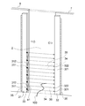
- FIG. 1 is a front view showing a door device according to Embodiment 1 of the present invention.
- FIG. 2 is an enlarged perspective view showing the door device of FIG.
- FIG. 3 is an enlarged top view showing the door device of FIG.
- a car 1 is arranged in a hoistway of an elevator so as to be movable in the vertical direction.
- the car 1 is provided with a car doorway 2.
- a hanger case 3 arranged above the car entrance 2 and a car sill 4 arranged below the car entrance 2 are fixed to the car 1.
- the door rail 5 arranged along the width direction of the car doorway 2 is fixed to the hanger case 3.
- a first car door 6 and a second car door 7 for opening and closing the car entrance 2 are suspended.
- the first car door 6 and the second car door 7 are movable along the door rail 5 in the width direction of the car entrance 2.
- the car doorway 2 is opened and closed by the first car door 6 and the second car door 7 moving in the width direction of the car doorway 2.
- the hanger case 3 is provided with a door driving device 8 and a driven pulley 10.
- the door driving device 8 and the driven pulley 10 are arranged above the door rail 5.
- the door driving device 8 is a device that generates a driving force for moving the first car door 6 and the second car door 7.
- the drive shaft of the door drive device 8 is provided with a drive pulley 9.
- the drive pulley 9 rotates about the drive shaft of the door drive device 8 by the drive force of the door drive device 8.
- the drive pulley 9 and the driven pulley 10 are arranged apart from each other in the width direction of the car entrance 2.
- An endless transmission belt 11 is wound around the driving pulley 9 and the driven pulley 10. The transmission belt 11 moves according to the rotation of the driving pulley 9.
- the first car door 6 and the second car door 7 are individually connected to the transmission belt 11 via the connecting member 12. Thereby, the first car door 6 and the second car door 7 move in opposite directions according to the movement of the transmission belt 11.
- the car doorway 2 is opened and closed by the first car door 6 and the second car door 7 moving in opposite directions. Therefore, the door device according to the present embodiment is a double door system of an elevator.
- the car sill 4 is arranged along the width direction of the car doorway 2.
- a sill groove (not shown) is provided in the car sill 4 along the moving direction of the first car door 6 and the second car door 7.
- Each of the first car door 6 and the second car door 7 includes a door panel 25 that opens and closes the car doorway 2, a door hanger 26 provided at an upper end of the door panel 25, and a plurality of legs provided at a lower end of the door panel 25.
- the respective door panels 25 of the first car door 6 and the second car door 7 are arranged on a straight line along the width direction of the car entrance 2 when viewed from above.
- Each door hanger 26 of the first car door 6 and the second car door 7 is hung on the door rail 5.
- Each leg of the first car door 6 and the second car door 7 is inserted into a sill groove of the car sill 4.
- Each floor of the building is provided with a landing entrance 21 which is a space connecting the landing and the inside of the hoistway, as shown in FIG.
- a landing threshold (not shown) is provided below the landing entrance 21 along the width direction of the landing entrance 21.
- a first landing door 22 and a second landing door 23 for opening and closing the landing entrance 21 are provided.
- the first car door 6 faces the first hall door 22 in the depth direction of the car entrance 2 and the hall entrance 21.
- the second car door 7 faces the second hall door 23 in the depth direction of the car entrance 2 and the landing entrance 21.
- the first car door 6 moves together with the first landing door 22 and the second car door 7 moves together with the second landing door 23, so that the car entrance 2 and the The landing entrance 21 is simultaneously opened and closed.
- the sensor 33 is provided for each of the first car door 6 and the first car door 7.
- the sensor 33 includes a light emitting side sensor unit 31 as a first sensor unit and a light receiving side sensor unit 32 as a second sensor unit.
- the light emitting side sensor unit 31 is attached to a door closing side end of the door panel 25 of the first car door 6 by a sensor attaching member 35.
- the light emitting side sensor unit 31 is arranged along the height direction of the first car door 6 and the first landing door 22. Further, the light-emitting side sensor unit 31 is disposed between the first car door 6 and the first landing door 22 when viewed from above.
- the light-receiving-side sensor section 32 is attached to the door-closed end of the door panel 25 of the second car door 7 by a sensor attaching member 35.
- the light receiving side sensor unit 32 is disposed along the height direction of the second car door 7 and the second landing door 23.
- the light-receiving-side sensor unit 32 is disposed between the second car door 7 and the second landing door 23 when viewed from above.
- the sensor mounting member 35 for mounting the light receiving side sensor unit 32 to the second car door 7 is arranged separately from the sensor mounting member 35 for mounting the light emitting side sensor unit 31 to the first car door 6.
- the light emitting side sensor unit 31 includes a plurality of first light emitting units 311 and a housing that is a support member that supports the plurality of first light emitting units 311.
- the housing of the light-emitting side sensor unit 31 has a light-emitting unit installation surface provided with a plurality of first light-emitting units 311.
- the plurality of first light projecting units 311 are arranged at an interval in the height direction of the first car door 6 and the first landing door 22.
- the light-receiving-side sensor unit 32 has a plurality of first light-receiving units 321 and a housing that is a support member that supports the plurality of first light-receiving units 321.
- the housing of the light-receiving side sensor unit 32 has a light-receiving unit installation surface provided with a plurality of first light-receiving units 321.
- the plurality of first light receiving units 321 are arranged at an interval in the height direction of the second car door 7 and the second landing door 23.
- the light emitting side sensor part 31 and the light receiving side sensor part 32 are arranged in a state where the plurality of first light emitting parts 311 and the plurality of first light receiving parts 321 are individually opposed to each other in the width direction of the car entrance 2. .
- the width direction of each of the light emitting side sensor unit 31 and the light receiving side sensor unit 32 coincides with the depth direction of the car entrance 2 and the landing entrance 21.
- the position of the light emitting unit installation surface of the light emitting side sensor unit 31 is the same as the end face of the first car door 6 on the door closing side of the door panel 25 in the width direction of the car doorway 2.
- the position of the light receiving unit installation surface of the light receiving side sensor unit 32 is the same as the door closing side end surface of the door panel 25 of the second car door 7 in the width direction of the car entrance 2.
- a plurality of linear first beam paths each connecting the first light projecting unit 311 and each first light receiving unit 321 are provided between the light projecting side sensor unit 31 and the light receiving side sensor unit 32. It is set as a detection area. Therefore, the plurality of first beam paths are set at intervals in the vertical direction on an imaginary plane parallel to both the width direction and the vertical direction of the car doorway 2. The plurality of first beam paths are set between the car entrance 2 and the landing entrance 21 as shown in FIG.
- Each first light projecting unit 311 projects the beam 34 toward each first light receiving unit 321.
- the beam 34 emitted from each first light projecting unit 311 passes through each first beam path and is received by each first light receiving unit 321.
- the beam 34 passing through the first beam path including the object is blocked by the object.
- the sensor 33 does not detect an object.
- the sensor 33 detects the object by stopping the reception of the beam 34 by at least one of the plurality of first light receiving units 321. That is, the sensor 33 detects whether an object has entered the first detection area based on whether or not each of the first light receiving units 321 has received the beam 34. Therefore, in this example, the sensor 33 is a photoelectric sensor.
- the car 1 is provided with a door control unit 20 as shown in FIG.
- Information from the sensor 33 indicating whether an object has entered the first beam path, which is the first detection area, is sent from the light receiving side sensor unit 32 to the door control unit 20.
- the door control unit 20 controls the door driving device 8 based on information from the sensor 33.
- the door control unit 20 controls the movement of the first car door 6, the second car door 7, the first landing door 22, and the second landing door 23 by controlling the door driving device 8.
- the door control unit 20 sets the first car door 6, the second car Control is performed to reverse the moving direction of the door 7, the first landing door 22, and the second landing door 23 from the door closing direction to the door opening direction.
- a plate-like guide member 41 is fixed to the sensor mounting member 35 for mounting the light-emitting side sensor section 31 to the first car door 6.
- the guide member 41 is formed integrally with the sensor mounting member 35.
- the guide member 41 is disposed along the height direction of the first car door 6 and the first landing door 22, as shown in FIG. Further, the guide member 41 is disposed in a range in the height direction of the first car door 6 and the first landing door 22.
- the guide member 41 may be disposed in the entire height range of the first car door 6 and the first landing door 22, or may be arranged in the height direction of the first car door 6 and the first landing door 22. May be arranged only in a part of.
- the position of the lower end surface of the guide member 41 coincides with the position of the lower surface of the door panel 25 of the first car door 6 in the vertical direction. Further, in this example, the position of the upper end surface of the guide member 41 is lower than the position of the upper end surface of the door panel 25 of the first car door 6.
- the guide member 41 is disposed between the door panel 25 of the first car door 6 and the light-emitting side sensor unit 31 as shown in FIG.
- the door closing side end of the guide member 41 protrudes toward the door closing side from the light emitting unit installation surface of the light emitting side sensor unit 31. Further, the position of the door closing side end of the guide member 41 is a position that does not protrude to the door closing side from the door closing side end surface of the first landing door 22.
- a plate-shaped pressing member 42 is fixed to the sensor mounting member 35 for mounting the light receiving side sensor unit 32 to the second car door 7.
- the pressing member 42 is formed integrally with the sensor mounting member 35.
- the holding member 42 is arranged along the height direction of the second car door 7 and the second landing door 23.
- the holding member 42 is arranged in a range in the height direction of the second car door 7 and the second landing door 23.
- the holding member 42 may be arranged in the entire height range of the second car door 7 and the second landing door 23, or may be arranged in the height direction of the second car door 7 and the second landing door 23. May be arranged only in a part of.
- the position of the lower end surface of the pressing member 42 coincides with the position of the lower end surface of the guide member 41 in the vertical direction.
- the position of the upper end surface of the pressing member 42 coincides with the position of the upper end surface of the guide member 41 in the vertical direction.
- the pressing member 42 is disposed between the door panel 25 of the second car door 7 and the light receiving side sensor unit 32.
- the door-closed end of the pressing member 42 protrudes toward the door-closed side from the light-receiving unit installation surface of the light-receiving sensor 32.
- a vertical surface 421 extending in the vertical direction is formed at the door closing end of the pressing member 42.
- the position of the up-down direction surface 421 of the holding member 42 is closer to the door opening side than the end surface of the second landing door 23 on the door closing side.
- the holding member 42 is arranged at a position displaced in the depth direction of the car entrance 2 and the landing entrance 21 with respect to the guide member 41. Thereby, even if the 1st car door 6, the 2nd car door 7, the 1st hall door 22, and the 2nd hall door 23 reach the fully closed position which fully closes the car doorway 2 and the hall doorway 21, the holding member is also provided. 42 does not interfere with the guide member 41. In a state where the first car door 6, the second car door 7, the first landing door 22, and the second landing door 23 are in the fully closed position, a part of the door closing side end of the guide member 41 is connected to the car entrance 2 and the landing. In the depth direction of the entrance 21, it overlaps with the door closing side end of the holding member 42.
- FIG. 4 is an enlarged front view showing the guide member 41 and the pressing member 42 of FIG.
- a plurality of first recesses 411 are formed at the door-closing end of the guide member 41 and are arranged in the up-down direction. Each position of the plurality of first recesses 411 in the up-down direction is set in accordance with each position of the plurality of first beam paths.
- a first guide surface 412 and second guide surfaces 413 and 414 connected to the first guide surface 412 are formed on the inner surface of each first recess 411.
- Each first guide surface 412 is an inclined surface inclined with respect to the horizontal.
- Each of the first guide surfaces 412 is inclined toward the door opening side of the first car door 6 from the upper end to the lower end of the first guide surface 412.
- the second guide surface 413 formed on the inner surface of each of the first recesses 411 other than the first recess 411 at the lowermost position is horizontally moved from the lower end of the first guide surface 412 to the door closing side of the first car door 6. It is a horizontal plane that extends.
- the second guide surface 414 formed on the inner surface of the first concave portion 411 at the lowermost position is inclined downward from the lower end of the first guide surface 412 toward the door closing side of the first car door 6. Plane. Therefore, a lowermost second guide surface 414 is formed at the lower end of the guide member 41 as a lower end inclined surface.
- first guide surface 412 and the second guide surface 413 are formed alternately and continuously upward at the door-closed end of the guide member 41 from the upper end of the second guide surface 414 at the lowest position. ing.
- the position of each first beam path corresponding to each first recess 411 is set based on the boundary between the first guide surface 412 and the second guide surfaces 413, 414.
- the long object 100 may be a string, a rod, or the like.
- the guide member 41 moves the long object 100 straddling the car doorway 2 and the landing doorway 21 by moving together with the first car door 6 and the first landing door 22 in a direction in which the car doorway 2 and the landing doorway 21 close. It is guided to a first beam path, which is one detection area.
- the guide member 41 guides the long object 100 along the first guide surface 412, and moves the long object 100 downward toward the boundary between the first guide surface 412 and the second guide surfaces 413, 414. Lead to.
- the guide member 41 guides the elongated object 100 along the second guide surface 414 at the lowermost position, and is elongated toward the boundary between the first guide surface 412 and the second guide surface 414.
- the object 100 is guided upward.
- the long object 100 that has reached one of the boundary between the first guide surface 412 and the second guide surface 413 and the boundary between the first guide surface 412 and the second guide surface 414 is the first object through which the beam 34 passes. Enter one beam path.
- the pressing member 42 presses the long object 100 by the guide member 41. Thereby, when the respective states of the car doorway 2 and the landing doorway 21 are in the fully closed state, the long object 100 is held between the guide member 41 and the pressing member 42.
- the door devices include a hanger case 3, a car sill 4, a door rail 5, a first car door 6, a second car door 7, a door driving device 8, a driving pulley 9, a driven pulley 10, a transmission belt 11, a connecting member 12, It has a door control unit 20, a landing threshold, a first landing door 22, a second landing door 23, an engagement device 24, a sensor 33, a sensor mounting member 35, a guide member 41, and a holding member 42.
- the long object 100 does not stay on the upper surface of the car sill 4 but on the second guide surface 414 at the lowest position.
- the beam 34 passing through the first beam path is blocked by the object 100, and the long object 100 is detected by the sensor 33.
- the long object 100 When the long object 100 straddles the car doorway 2 and the landing doorway 21 in the air away from the car threshold 4, the first car door 6, the second car door 7, the first landing door 22 and When the closing operation of the second landing door 23 is started, the long object 100 comes into contact with the first guide surface 412.
- the long object 100 does not stay between the two first beam paths and follows the first guide surface 412. To the first beam path below. Thereby, the beam 34 passing through the first beam path is blocked by the object 100, and the long object 100 is detected by the sensor 33.
- the guide member 41 is disposed between the first car door 6 and the first landing door 22.
- the guide member 41 is arranged in a range in the height direction of the first car door 6 and the first landing door 22 without the guide member 41 interfering with each of the first car door 6 and the first landing door 22. be able to.
- the object 100 can be more reliably guided to the first beam path of the sensor 33 by the guide member 41. Therefore, the object 100 straddling between the car entrance 2 and the landing entrance 21 can be detected more reliably.
- the long object 100 can be guided by the guide member 41 to the first beam path of the sensor 33. Therefore, the number of first beam paths of the sensor 33 can be reduced, and the first detection area of the sensor 33 can be reduced. Thereby, the cost of the sensor 33 can be reduced.
- the guide member 41 is disposed between the first car door 6 and the light-emitting side sensor unit 31. For this reason, the guide member 41 can be arranged in the gap between the first car door 6 and the light emitting side sensor unit 31, and the guide member 41 can be easily attached to the existing first car door 6. That is, by disposing the guide member 41 between the first car door 6 and the light emitting side sensor section 31, it is possible to prevent the installation space of the guide member 41 from increasing toward the landing. Thereby, the guide member 41 can be easily attached to the existing first car door 6 while maintaining the distance between the car entrance 2 and the landing entrance 21.
- the pressing member 42 is disposed between the second car door 7 and the light-receiving-side sensor unit 32. For this reason, the pressing member 42 can be arranged in the gap between the second car door 7 and the light receiving side sensor unit 32, and the pressing member 42 can be easily attached to the existing second car door 7.
- the guide member 41 is provided on the sensor mounting member 35 for mounting the light emitting side sensor unit 31 to the first car door 6. For this reason, the guide member 41 and the sensor mounting member 35 can be handled as an integral part. Thereby, the number of parts can be reduced. In addition, the work of adjusting the positional relationship between the light emitting side sensor unit 31 and the guide member 41 can be facilitated. Therefore, it is possible to reduce the burden on the manufacturing operation of the door device, and it is possible to reduce the manufacturing cost.
- the pressing member 42 is provided on the sensor mounting member 35 for mounting the light-receiving-side sensor unit 32 to the second car door 7. For this reason, the pressing member 42 and the sensor mounting member 35 can be handled as an integral part. Thereby, the number of parts can be reduced. In addition, the operation of adjusting the positional relationship between the light receiving side sensor unit 32 and the pressing member 42 can be facilitated. Therefore, it is possible to reduce the burden on the manufacturing operation of the door device, and it is possible to reduce the manufacturing cost.
- the pressing member 42 is arranged at a position displaced in the depth direction of the car doorway 2 and the landing doorway 21 with respect to the guide member 41. For this reason, it is possible to more reliably press the long object 100 on the guide member 41 by the pressing member 42 while avoiding the pressing member 42 from interfering with the guide member 41.
- the guide member 41 has a first guide surface 412 that guides the long object 100 to the first beam path below. For this reason, the long object 100 can be guided in a direction that does not oppose the gravity applied to the long object 100, and guidance of the long object 100 to the first beam path can be further ensured.
- a second guide surface 414 at a lowermost position for guiding the elongated object 100 to the upper first beam path is formed. For this reason, it is easy to set the long object 100 without setting the first beam path at the height of the lower surface of the first car door 6 and the second car door 7 for which it is difficult to set the first beam path. And it can detect more reliably.
- Embodiment 2 FIG.
- the up-down direction surface 421 along the up-down direction is formed at the door closing side end of the holding member 42.
- a plurality of second concave portions may be formed at the door closing end of the holding member 42.
- FIG. 5 is an enlarged front view showing the guide member 41 and the pressing member 42 in the door device according to Embodiment 2 of the present invention.
- a plurality of second concave portions 422 arranged in the up-down direction are formed at the door closing side end of the pressing member 42.
- the respective positions of the plurality of second recesses 422 in the vertical direction are set in accordance with the respective positions of the plurality of first beam paths.
- first pressing surface 423 and second pressing surfaces 424 and 425 connected to the first pressing surface 423 are formed on the inner surface of each second concave portion 422.
- the first pressing surface 423 is an inclined surface inclined with respect to the horizontal.
- the first pressing surface 423 is inclined from the upper end to the lower end of the first pressing surface 423 toward the door opening side of the second car door 7.
- the second pressing surface 424 formed on the inner surface of each of the second concave portions 422 other than the lowermost second concave portion 422 is horizontally moved from the lower end of the first pressing surface 423 to the door closing side of the second car door 7. It is a horizontal plane that extends.
- the second pressing surface 425 formed on the inner surface of the second concave portion 422 at the lowermost position is inclined downward from the lower end of the first pressing surface 423 toward the door closing side of the second car door 7. Plane. Therefore, the lowermost second pressing surface 425 is formed at the lower end of the pressing member 42 as a lower end inclined surface.
- the first pressing surface 423 and the second pressing surface 424 are continuously formed alternately upward from the upper end of the second pressing surface 425 at the lowest position. ing.
- the position of each first beam path corresponding to each second recess 422 is set based on the boundary between the first pressing surface 423 and the second pressing surfaces 424, 425.
- the pressing member 42 presses the long object 100 by the guide member 41 as shown in FIG.
- the long object 100 is sandwiched between the first recess 411 and the second recess 422.
- the long object 100 is held between the guide member 41 and the pressing member 42.
- Other configurations are the same as in the first embodiment.
- the first recess 411 is formed in the guide member 41, and the second recess 422 is formed in the pressing member 42.
- the long object 100 can be sandwiched between the first recess 411 and the second recess 422, and the long object 100 is guided to the first beam path by each of the guide member 41 and the holding member 42. Can be.
- the long object 100 can be more reliably guided to the first beam path, which is the first detection area, and the long object 100 can be detected more reliably.
- the light emitting side sensor unit 31 is provided on the first car door 6 and the light receiving side sensor unit 32 is provided on the second car door 7.
- the light emitting side sensor unit 31 may be provided on the first landing door 22 and the light receiving side sensor unit 32 may be provided on the second landing door 23.
- a guide member 41 is provided on a sensor mounting member for attaching the light emitting side sensor unit 31 to the first landing door 22, and a pressing member 42 is provided on a sensor mounting member for attaching the light receiving side sensor unit 32 to the second landing door 23.
- the guide member 41 is disposed between the light-emitting side sensor unit 31 and the first landing door 22.
- the pressing member 42 is disposed between the light receiving side sensor unit 32 and the second landing door 23.
- the sensor 33 that detects the long object 100 is a photoelectric sensor.
- the sensor that detects the long object 100 may be a camera.
- FIG. 6 is an enlarged front view showing the guide member 41 and the pressing member 42 in the door device according to Embodiment 3 of the present invention.
- a camera (not shown) is arranged between the car entrance 2 and the landing entrance 21 as a sensor.
- the camera is provided on the first car door 6.
- the camera is arranged at the position of the light emitting side sensor unit 31 of the first embodiment.
- the detection area of the camera is a first detection area along the moving direction of the first car door 6 and the first landing door 22, that is, the width direction of the car entrance 2 and the landing entrance 21.
- the detection area of the camera is a band-shaped area having a set width D in the vertical direction. The camera detects the long object 100 when the object 100 enters the detection area of the camera.
- An upper guide surface 415 and a lower guide surface 416 that are vertically separated from each other and an intermediate surface 417 that connects the upper guide surface 415 and the lower guide surface 416 to each other are formed at the door closing side end of the guide member 41. I have.
- the upper guide surface 415 is formed at the upper end of the guide member 41.
- the upper guide surface 415 is inclined toward the door opening side of the first car door 6 from the upper end to the lower end of the upper guide surface 415.
- the lower guide surface 416 is formed at the lower end of the guide member 41. Further, the lower guide surface 416 is inclined toward the door opening side of the first car door 6 from the lower end to the upper end of the lower guide surface 416.
- the intermediate surface 417 is a surface connecting the lower end of the upper guide surface 415 and the upper end of the lower guide surface 416.
- the intermediate surface 417 extends along the up-down direction.
- the vertical positions of the upper guide surface 415, the lower guide surface 416, and the intermediate surface 417 are set in accordance with the detection area of the camera.
- the position of the upper guide surface 415 is set at a position deviated upward from the detection area of the camera.
- the position of the lower guide surface 416 is set at a position deviated downward from the detection area of the camera.
- the position of the intermediate plane 417 is set within the detection area of the camera.
- the guide member 41 moves in a direction in which the car doorway 2 and the landing doorway 21 are closed, so that the long object 100 is moved to the upper guide surface 415.
- the light is guided to the detection area of the camera along the lower guide surface 416.
- a camera is used as a sensor for detecting the long object 100.
- a pressure-sensitive sensor may be used as a sensor for detecting the long object 100.
- the first detection area which is the detection area of the pressure-sensitive sensor, is the area of the pressure-sensitive surface set for the pressure-sensitive sensor.
- the pressure sensor is attached to the intermediate surface 417 of the guide member 41. Even in this case, the long object 100 can be guided to the detection area of the pressure-sensitive sensor, and the long object 100 can be detected more reliably.
- the pressure sensor only needs to be disposed at a position where the long object 100 guided by the guide member 41 contacts. Therefore, the pressure-sensitive sensor may be attached to the first car door 6 instead of the guide member 41, for example.
- the first detection region of the sensor is a region along the width direction of the car entrance 2 and the landing entrance 21.
- the first detection region of the sensor may be a region along the vertical direction.
- FIG. 7 is an enlarged front view showing the guide member 41 and the pressing member 42 in the door device according to Embodiment 4 of the present invention.
- a sensor that detects the long object 100 is a photoelectric sensor.
- the configuration of the photoelectric sensor according to the present embodiment is the same as the configuration of the sensor 33 according to the first embodiment.
- a plurality of first beam paths through which the sensor beam 34 passes are set along the vertical direction.
- the light emitting side sensor section which is the first sensor section included in the sensor, is provided in the hanger case 3.
- the light-receiving-side sensor unit, which is the second sensor unit included in the sensor, is provided on the side surface in the width direction of the car sill 4.
- the first beam path of the sensor that is, the first detection area, is set only in the central area in the width direction of the car entrance 2 and the landing entrance 21.
- Other configurations are the same as those of the third embodiment.
- the guide member 41 moves in a direction in which the car doorway 2 and the landing doorway 21 are closed, so that the long object 100 is moved to the upper guide surface 415.
- the light is guided to the first detection area of the sensor along the lower guide surface 416.
- the pressing member 42 presses the long object 100 by the guide member 41 as shown in FIG.
- the long object 100 is held between the guide member 41 and the pressing member 42 in the first detection area of the sensor.
- the guide member 41 moves in the direction in which the car entrance 2 and the landing entrance 21 are closed, The long object 100 can be guided to the first detection area of the sensor. Thereby, the long object 100 can be detected more reliably.
- a camera may be used as a sensor for detecting the object 100.
- the camera is attached to the hanger case 3.
- a camera may be mounted above the landing entrance 21.
- the sensors for detecting the object 100 are attached to the hanger case 3 and the car sill 4.
- sensors for detecting the object 100 may be attached to the upper and lower portions of the landing entrance 21.
- FIG. FIG. 8 is an enlarged top view showing a door device according to Embodiment 5 of the present invention.
- the guide member 41 is attached to the door panel 25 of the first car door 6 by a component attaching member 51.
- the component attachment member 51 for attaching the guide member 41 to the first car door 6 is a separate member from the sensor attachment member 35 for attaching the light emitting side sensor unit 31 to the first car door 6.
- the guide member 41 is disposed between the light emitting side sensor unit 31 and the first landing door 22.
- the holding member 42 is attached to the door panel 25 of the second car door 7 by the component attaching member 51.
- the component attachment member 51 for attaching the holding member 42 to the second car door 7 is a separate member from the sensor attachment member 35 for attaching the light receiving side sensor 32 to the second car door 7.
- the pressing member 42 is disposed between the light receiving side sensor unit 32 and the second landing door 23.
- the holding member 42 is arranged at a position displaced in the depth direction of the car entrance 2 and the landing entrance 21 with respect to the guide member 41. Thereby, even when the state of the car doorway 2 and the landing doorway 21 is in the fully closed state, the pressing member 42 does not interfere with the guide member 41.
- Other configurations are the same as in the first embodiment.
- the guide member 41 is disposed between the light emitting side sensor unit 31 and the first landing door 22. For this reason, the guide member 41 can be easily arranged avoiding the light emitting side sensor unit 31. Further, the lower portion of the guide member 41 can be inserted into a gap between the car threshold 4 and the landing threshold. Thereby, even when the long object 100 straddling the car entrance 2 and the landing entrance 21 is placed on the car threshold 4 and the landing threshold, the long object 100 is more reliably guided to the first detection area of the sensor 33. Can be. Further, the distance from each of the first car door 6 and the first landing door 22 to the guide member 41 can be easily adjusted. Thereby, the guide member 41 can be made difficult to see from the passengers inside the car 1 and at the landing.
- the pressing member 42 is disposed between the light-receiving-side sensor unit 32 and the second landing door 23. For this reason, the pressing member 42 can be easily arranged avoiding the light receiving side sensor unit 32. Further, the lower part of the holding member 42 can be inserted into a gap between the car threshold 4 and the landing threshold. Thus, the long object 100 guided to the first detection area of the sensor 33 by the guide member 41 can be held more reliably. Further, the distance from each of the second car door 7 and the second landing door 23 to the pressing member 42 can be easily adjusted. This makes it possible to make the pressing member 42 invisible to the passengers inside the car 1 and at the landing.
- the light emitting side sensor unit 31 is provided on the first car door 6 and the light receiving side sensor unit 32 is provided on the second car door 7.
- the light emitting side sensor unit 31 may be provided on the first landing door 22 and the light receiving side sensor unit 32 may be provided on the second landing door 23.
- the guide member 41 is attached to the first landing door 22 by the component attachment member 51
- the pressing member 42 is attached to the second landing door 23 by the component attachment member 51.
- a guide member 41 is disposed between the light emitting side sensor unit 31 and the first car door 6, and a pressing member 42 is disposed between the light receiving side sensor unit 32 and the second car door 7. .
- the component mounting member 51 is a separate member from the sensor mounting member 35.
- the component mounting member 51 may be a single material integrated with the sensor mounting member 35. In this case, the number of components can be reduced, and the manufacturing cost of the door device can be reduced.
- FIG. 9 is an enlarged top view showing a door device according to Embodiment 6 of the present invention.
- the guide member 41 is provided in the light emitting side sensor unit 31. Further, the guide member 41 is attached to the light emitting unit installation surface, avoiding each of the first light emitting units 311. Further, the guide member 41 is disposed within a range in the width direction of the light emitting side sensor unit 31 when viewed from above. That is, the guide member 41 is arranged within the range of the light-emitting side sensor unit 31 in the depth direction of the car entrance 2 and the landing entrance 21. In this example, the guide member 41 is a separate member from the housing of the light emitting side sensor unit 31.
- the pressing member 42 is provided in the light receiving side sensor unit 32.
- the pressing member 42 is attached to the light receiving unit installation surface, avoiding each of the first light receiving units 321.
- the holding member 42 is disposed within a range in the width direction of the light receiving side sensor unit 32 when viewed from above. That is, the holding member 42 is disposed within the range of the light receiving side sensor unit 32 in the depth direction of the car entrance 2 and the landing entrance 21.
- the pressing member 42 is a separate member from the housing of the light receiving side sensor unit 32.
- the holding member 42 is arranged at a position displaced in the depth direction of the car entrance 2 and the landing entrance 21 with respect to the guide member 41. Thereby, even when the state of the car doorway 2 and the landing doorway 21 is in the fully closed state, the pressing member 42 does not interfere with the guide member 41.
- Other configurations are the same as in the first embodiment.
- the guide member 41 is provided in the light emitting side sensor unit 31.
- the guide member 41 can be arranged within the range in the width direction of the light emitting side sensor unit 31.
- the guide member 41 is a separate member from the housing of the light emitting side sensor unit 31.
- the housing of the light emitting side sensor unit 31 and the guide member 41 may be formed of a single material. In this way, the light emitting side sensor 31 and the guide member 41 can be simultaneously attached to the first car door 6, and the work of attaching the light emitting side sensor 31 and the guide member 41 can be facilitated.
- the pressing member 42 is a separate member from the housing of the light receiving side sensor unit 32.
- the housing of the light receiving side sensor unit 32 and the pressing member 42 may be formed of a single material. With this configuration, the light receiving side sensor 32 and the pressing member 42 can be simultaneously attached to the second car door 7, and the work of mounting the light receiving side sensor 32 and the pressing member 42 can be facilitated.
- the light emitting side sensor unit 31 is provided on the first car door 6.
- the light emitting side sensor unit 31 may be provided on the first landing door 22.
- the light-receiving-side sensor unit 32 is provided on the second car door 7.
- the light receiving side sensor unit 32 may be provided on the second landing door 23.
- FIG. FIG. 10 is an enlarged top view showing a door device according to Embodiment 7 of the present invention.
- the guide member 41 is disposed between the first car door 6 and the light emitting side sensor unit 31.
- the guide member 41 is attached to the door panel 25 of the first car door 6 in the same manner as in the first embodiment. That is, the guide member 41 is attached to the first car door 6 by the sensor attaching member 35 to which the light emitting side sensor unit 31 is attached.
- the holding member 42 is disposed between the second landing door 23 and the light receiving side sensor unit 32.
- the holding member 42 is attached to the door panel 25 of the second car door 7 in the same manner as in the fifth embodiment. That is, the pressing member 42 is attached to the door panel 25 of the second car door 7 by a component attaching member 51 separate from the sensor attaching member 35.
- the guide member 41 and the pressing member 42 are disposed on the opposite sides with respect to a straight line connecting the light emitting side sensor unit 31 and the light receiving side sensor unit 32, that is, the linear first beam path. ing.
- Other configurations are the same as in the first embodiment.
- the guide member 41 and the pressing member 42 are arranged on opposite sides with respect to a straight line connecting the light emitting side sensor unit 31 and the light receiving side sensor unit 32. For this reason, when the state of the car doorway 2 and the landing doorway 21 is in the fully closed state, the interference between the pressing member 42 and the guide member 41 can be more reliably prevented. Further, a first beam path can be set between the guide member 41 and the holding member 42. Therefore, the long object 100 can be guided to the first beam path of the sensor between the guide member 41 and the holding member 42. Thereby, the long object 100 can be detected more reliably.
- the guide member 41 is disposed between the light-emitting side sensor section 31 and the first car door 6, and the pressing member 42 is disposed between the light-receiving side sensor section 32 and the second landing door 23.
- the positional relationship between the guide member 41 and the pressing member 42 is not limited to this.
- the guide member 41 and the pressing member 42 are disposed on opposite sides with respect to a straight line connecting the light emitting side sensor unit 31 and the light receiving side sensor unit 32, the light emitting side sensor unit 31
- the guide is guided to one of a position between the first car door 6 and the first car door 6, a position within a range in the width direction of the light emitting side sensor unit 31, and a position between the light emitting side sensor unit 31 and the first landing door 22.
- the member 41 can be arranged. Further, a position between the light receiving side sensor unit 32 and the second car door 7, a position within a range in the width direction of the light receiving side sensor unit 32, and a position between the light receiving side sensor unit 32 and the second landing door 23.
- the holding member 42 can be arranged at any of the positions.
- FIG. 11 is an enlarged perspective view showing a door device according to Embodiment 8 of the present invention.
- FIG. 12 is an enlarged front view showing a guide member and a pressing member of the door device of FIG.
- the light emitting side sensor unit 31 includes a plurality of first light emitting units 311, a plurality of second light emitting units 312, and a housing in which each of the first light emitting units 311 and each of the second light emitting units 312 are installed. have.
- the configuration of the housing of the light emitting side sensor unit 31 is the same as that of the first embodiment.
- the plurality of first light emitting units 311 and the plurality of second light emitting units 312 are provided on the light emitting unit installation surface of the housing.
- the plurality of first light projecting units 311 are arranged at an interval in the height direction of the first car door 6 and the first landing door 22.
- the plurality of second light emitting units 312 are arranged at an interval in the height direction of the first car door 6 and the first landing door 22.
- the first light emitting units 311 and the second light emitting units 312 are alternately arranged in the height direction of the first car door 6 and the first landing door 22.
- the light receiving side sensor unit 32 includes a plurality of first light receiving units 321, a plurality of second light receiving units 322, and a housing in which each of the first light receiving units 321 and each of the second light receiving units 322 are installed. .
- the configuration of the housing of the light receiving side sensor unit 32 is the same as that of the first embodiment.
- the plurality of first light receiving units 321 and the plurality of second light receiving units 322 are provided on a light receiving unit installation surface of a common housing.
- the plurality of first light receiving units 321 are arranged at an interval in the height direction of the second car door 7 and the second landing door 23.
- the plurality of second light receiving units 322 are arranged at an interval in the height direction of the second car door 7 and the second landing door 23.
- the first light receiving units 321 and the second light receiving units 322 are alternately arranged in the height direction of the second car door 7 and the second landing door 23.
- the plurality of first light emitting units 311 and the plurality of first light receiving units 321 individually face each other in the width direction of the car entrance 2.
- the plurality of second light emitting units 312 and the plurality of second light receiving units 322 individually face each other in the width direction of the car entrance 2.
- Each first beam path is set as a first detection area.
- Each second beam path is set as a second detection area at a position different from each first detection area.
- a plurality of first beam paths and a plurality of second beam paths are alternately arranged in the vertical direction.
- each first beam path with respect to the guide member 41 is set based on the boundary between the first guide surface 412 and the second guide surfaces 413 and 414 as in the first embodiment.
- the vertical position of each second beam path with respect to the guide member 41 is set at a position farther from the boundary between the first guide surface 412 and the second guide surfaces 413 and 414 than the position of the first beam path. .
- Each first light projecting unit 311 projects the beam 34 toward each first light receiving unit 321.
- the beam 34 emitted from each first light projecting unit 311 passes through each first beam path and is received by each first light receiving unit 321.
- Each second light projecting unit 312 projects the beam 36 toward each second light receiving unit 322.
- the beam 36 emitted from each second light projecting unit 312 passes through each second beam path and is received by each second light receiving unit 322.
- the functions of the sensor 33 include a first sensor function for detecting an object entering the first beam path and a second sensor function for detecting an object entering the second beam path. Therefore, the first sensor function of the sensor 33 is a function of detecting an object by the first light projecting unit 311 and the first light receiving unit 321. The second sensor function of the sensor 33 is a function of detecting an object by the second light emitting unit 312 and the second light receiving unit 322.
- the lower limit of the size of the object that can be detected by the first sensor function is smaller than the lower limit of the size of the object that can be detected by the second sensor function. That is, the sensor 33 can detect an object whose first sensor function is smaller than that of the second sensor function.
- the sensor 33 detects a thin and long object 100 by a first sensor function, and detects a large object by a second sensor function. As the large object, a person, luggage, and the like can be considered.
- the diameter of the beam 34 emitted from each of the first light projecting units 311 is narrowed to be smaller than the diameter of the beam 36 emitted from each of the second light projecting units 312.
- the intensity of the beam 34 emitted from the first light projecting unit 311 is adjusted to be different from the intensity of the beam 36 emitted from the second light projecting unit 312.
- the light receiving sensitivity of the first light receiving unit 321 is adjusted to be different from the light receiving sensitivity of the second light receiving unit 322.
- the beam 34 passing through the first beam path including the object 100 is blocked by the object 100. Thereby, the long object 100 is detected by the sensor 33.
- the beam 36 passing through the second beam path containing the large object is blocked by the object. Thereby, a large object is detected by the sensor 33.
- the sensor 33 sends information indicating whether the object is detected by the first sensor function and the second sensor function to the door control unit 20.
- the door control unit 20 determines whether the first car door 6, the second car door 7, the first landing door 22, and the second landing door 23 are based on the detection of an object by each of the first sensor function and the second sensor function. Control movement. Other configurations are the same as in the first embodiment.
- the lower limit of the size of the object that can be detected by the first sensor function is smaller than the lower limit of the size of the object that can be detected by the second sensor function. For this reason, a thin long object such as a string and a large object such as a human can be distinguished and detected, and different control can be performed according to each of the thin long object and the large object. . Further, the long object 100 guided to the first beam path by the guide member 41 can be more reliably detected by the first sensor function.
- a plurality of first beam paths and a plurality of second beam paths are respectively set between the light emitting side sensor unit 31 and the light receiving side sensor unit 32.
- the sensor 33 can have two types of functions, the first sensor function and the second sensor function, by one combination of the light emitting side sensor unit 31 and the light receiving side sensor unit 32. This makes it possible to prevent the sensor 33 from having two types of functions and to prevent the light-emitting side sensor unit 31 and the light-receiving side sensor unit 32 from increasing the installation space.
- Embodiment 9 FIG.
- the configuration of the door device according to the present embodiment is the same as the configuration of the eighth embodiment shown in FIGS. 11 and 12 except for the control of the door control unit 20.
- the movement section from the fully open position to the fully closed position of the first car door 6, the second car door 7, the first landing door 22, and the second landing door 23, that is, the opening and closing movement section, is a detection section of the first sensor function.
- a detection section of the second sensor function is set closer to the door than the detection section of the second sensor function.
- the detection section of the first sensor function is a section of 20 mm from the fully closed position to the door opening side.
- the detection section of the second sensor function is a section obtained by removing the detection section of the first sensor function from the opening and closing movement section of the door.
- the door control unit 20 determines whether the first car door 6, the second car door 7, or the first landing door is based on whether an object is detected by the first sensor function. 22 and the movement of the second landing door 23 are controlled. Further, when a door is present in the detection section of the second sensor function, the door control unit 20 determines whether the first car door 6, the second car door 7, the first car door 7, The movement of the landing door 22 and the second landing door 23 is controlled. That is, the door control unit 20 performs one of the first sensor function and the second sensor function based on the positions of the first car door 6, the second car door 7, the first landing door 22, and the second landing door 23. The movement of the first car door 6, the second car door 7, the first landing door 22, and the second landing door 23 is controlled based on the information on whether or not an object is detected by the selected function.
- FIG. 13 is a flowchart showing processing of the door control unit of the door device according to Embodiment 9 of the present invention.
- the door control unit 20 determines whether or not the position of the door is at the fully open position in step S1.
- step S1 If it is determined in step S1 that the door position is not at the fully open position, the door control unit 20 repeats the determination whether the door position is at the fully open position. On the other hand, if it is determined in step S1 that the position of the door is at the fully open position, the process proceeds to step S2.
- step S2 the door control unit 20 determines whether an object is detected by the second sensor function of the sensor 33.
- step S2 If it is determined in step S2 that an object has been detected by the second sensor function, the process proceeds to step S3. On the other hand, if no object is detected by the second sensor function in step S2, the process proceeds to step S4.
- step S3 the door control unit 20 performs the door opening operation. Thereafter, the process returns to step S1.
- step S4 the door control unit 20 starts the door closing operation. Thereafter, the process proceeds to step S5.
- step S5 the door control unit 20 determines whether or not the position of the door is within the detection section of the first sensor function.
- step S5 If it is determined in step S5 that the position of the door is not within the detection section of the first sensor function, the process returns to step S2. As a result, the door control unit 20 repeats the processes of step S2, step S4, and step S5 until the position of the door enters the detection section of the first sensor function.
- step S5 If it is determined in step S5 that the position of the door is within the detection section of the first sensor function, the process proceeds to step S6.
- step S6 the door control unit 20 determines whether an object is detected by the first sensor function of the sensor 33.
- step S6 If it is determined in step S6 that an object has been detected by the first sensor function, the process proceeds to step S3. Thus, the door control unit 20 controls the opening operation of the door by reversing the movement of the door. On the other hand, if it is determined in step S6 that the object has not been detected by the first sensor function, the process proceeds to step S7.
- step S7 the door control unit 20 determines whether the position of the door is the fully closed position. If it is determined that the position of the door is not at the fully closed position, the process returns to step S6. Thereby, the door control unit 20 repeats the processing of step S6 and the processing of step S7 until the position of the door reaches the fully closed position. On the other hand, when it is determined that the position of the door is the fully closed position, the process returns to step S1.
- one of the first sensor function and the second sensor function of the sensor 33 is selected based on the position of the door, and the door function is selected based on the information on the presence or absence of the detection of the object by the selected function. Movement is controlled. Therefore, for example, the long object 100 can be detected by the first sensor function of the sensor 33 at a door position where a large object is unlikely to pass through the car entrance 2 and the landing entrance 21. Thereby, the malfunction of the sensor 33 can be reduced.
- the length of the detection section of the first sensor function and the length of the detection section of the second sensor function are fixed lengths.
- the length of the detection section of the first sensor function and the length of the detection section of the second sensor function may be respectively variable.
- a part of the detection section of the first sensor function may overlap with the detection section of the second sensor function.
- one of the first sensor function and the second sensor function of the sensor 33 is selected based on the position of the door, and the control of the door control unit 20 is performed based on the selected function.
- the detection condition for the sensor 33 to detect an object by the first sensor function may be different from the detection condition for the sensor 33 to detect the object by the second sensor function.
- the time required from when the object enters the first beam path until the object is detected by the first sensor function, and the time required after the object enters the second beam path and the object is detected by the second sensor function. Time may be different from each other.
- the number of beams 34 blocked by the object for detecting the object by the first sensor function and the number of beams 36 blocked by the object for detecting the object by the second sensor function are different from each other. You may.
- the detection condition for the sensor 33 to detect the object by the first sensor function and the detection condition for the sensor 33 to detect the object by the second sensor function are different from each other, so that the malfunction of the sensor 33 is reduced. be able to.
- Embodiment 10 FIG.
- the configuration of the door device according to the present embodiment is the same as the configuration of the first embodiment except for the control of the door control unit 20.
- Information from the door control unit 20 is sent to an elevator control device that controls the operation of the elevator.
- the elevator control device controls the movement of the car 1 based on the information from the door control unit 20.
- the door control unit 20 outputs a door fully closed signal to the elevator control device when the car entrance 2 and the landing entrance 21 are completely closed.
- the door fully closed signal from the door control unit 20 is sent to the elevator control device, the car 1 can be moved under the control of the elevator control device.
- the door control unit 20 When the sensor 33 detects the long object 100 after the movement of the car 1 is started under the control of the elevator control device, the door control unit 20 outputs a stop signal for stopping the car to the elevator control device. When a stop signal from the door control unit 20 is sent to the elevator control device, the car 1 is emergency stopped under the control of the elevator control device.
- FIG. 14 is a flowchart showing processing of the door control unit of the door device according to Embodiment 10 of the present invention.
- the door control unit 20 determines whether the car 1 is moving based on information from the elevator control device.
- step S11 If it is determined in step S11 that the car 1 has not moved, the door control unit 20 repeats the determination whether the car 1 has moved. On the other hand, if it is determined in step S11 that the car 1 is moving, the process proceeds to step S12.
- step S12 the door control unit 20 determines whether the sensor 33 has detected the long object 100.
- step S12 If it is determined in step S12 that the sensor 33 has detected the object 100, the process proceeds to step S13. On the other hand, if it is determined in step S12 that the sensor 33 has not detected the object 100, the process proceeds to step S14.
- step S13 the door control unit 20 outputs a stop signal for stopping the movement of the car 1 to the elevator control device. Thereby, the movement of the car 1 is stopped in an emergency under the control of the elevator controller.
- step S14 the door control unit 20 determines whether or not the set time X has elapsed after the start of the movement of the car 1.
- the set time X is, for example, several seconds.
- step S14 If it is determined in step S14 that the set time X has not elapsed, the door control unit 20 repeats the processing of step S12 and the processing of step S14 until the set time X has elapsed. On the other hand, if it is determined in step S14 that the set time X has elapsed, the process returns to step S11.
- the door control unit 20 when the sensor 33 detects the object 100 after the start of the movement of the car 1, the door control unit 20 outputs a stop signal for stopping the car 1. For this reason, even if the movement of the car 1 is started in a state where the long object 100 is straddling the car entrance 2 and the landing entrance 21, the long object 100 moves with the movement of the car 1. Thereby, the sensor 33 can be set in a state where the long object 100 can be detected. Thus, it is possible to prevent the movement of the car 1 from continuing, and it is possible to prevent a failure of the elevator.
- the control of the door control unit 20 that outputs a stop signal for stopping the car 1 when the sensor 33 detects the long object 100 is the door according to the first embodiment. Applied to the device. However, after the movement of the car 1 is started, the control of the door control unit 20 that outputs a stop signal for stopping the car 1 when the sensor 33 detects the long object 100 is applied to the door devices according to the second to ninth embodiments. May be.
- the light emitting side sensor unit 31 is provided on the first car door 6 and the light receiving side sensor unit 32 is provided on the second car door 7.
- the light receiving side sensor unit 32 may be provided on the first car door 6 and the light emitting side sensor unit 31 may be provided on the second car door 7.
Landscapes
- Elevator Door Apparatuses (AREA)
Abstract
L'invention porte sur un dispositif de porte dans lequel une première porte de cabine ouvre et ferme une embrasure de porte de cabine. Une première porte palière ouvre et ferme une porte palière en se déplaçant conjointement avec la première porte de cabine tout en faisant face à la première porte de cabine. Un capteur détecte un objet qui a pénétré dans une première région de détection. Un élément de guidage est disposé entre la première porte de cabine et la première porte palière. En outre, l'élément de guidage est disposé dans une plage dans le sens de la hauteur de la première porte de cabine et de la première porte palière. De plus, l'élément de guidage guide un objet allongé s'étendant à travers la porte de cabine et la porte palière jusqu'à la première région de détection en se déplaçant, conjointement avec la première porte de cabine et la première porte palière, dans la direction de fermeture de l'encadrement de porte de cabine et de l'encadrement de porte palière.
Priority Applications (3)
| Application Number | Priority Date | Filing Date | Title |
|---|---|---|---|
| PCT/JP2018/024637 WO2020003448A1 (fr) | 2018-06-28 | 2018-06-28 | Dispositif de porte |
| JP2020526813A JP6949225B2 (ja) | 2018-06-28 | 2018-06-28 | ドア装置 |
| CN201880094891.8A CN112334405B (zh) | 2018-06-28 | 2018-06-28 | 门装置 |
Applications Claiming Priority (1)
| Application Number | Priority Date | Filing Date | Title |
|---|---|---|---|
| PCT/JP2018/024637 WO2020003448A1 (fr) | 2018-06-28 | 2018-06-28 | Dispositif de porte |
Publications (1)
| Publication Number | Publication Date |
|---|---|
| WO2020003448A1 true WO2020003448A1 (fr) | 2020-01-02 |
Family
ID=68984925
Family Applications (1)
| Application Number | Title | Priority Date | Filing Date |
|---|---|---|---|
| PCT/JP2018/024637 Ceased WO2020003448A1 (fr) | 2018-06-28 | 2018-06-28 | Dispositif de porte |
Country Status (3)
| Country | Link |
|---|---|
| JP (1) | JP6949225B2 (fr) |
| CN (1) | CN112334405B (fr) |
| WO (1) | WO2020003448A1 (fr) |
Cited By (1)
| Publication number | Priority date | Publication date | Assignee | Title |
|---|---|---|---|---|
| US20210179390A1 (en) * | 2018-10-23 | 2021-06-17 | Mitsubishi Electric Corporation | Door-pinch detection device and elevator door device |
Families Citing this family (1)
| Publication number | Priority date | Publication date | Assignee | Title |
|---|---|---|---|---|
| CN115535813B (zh) * | 2021-06-30 | 2025-10-28 | 上海三菱电梯有限公司 | 电梯安全检测装置 |
Citations (7)
| Publication number | Priority date | Publication date | Assignee | Title |
|---|---|---|---|---|
| JPS5048362U (fr) * | 1973-08-29 | 1975-05-13 | ||
| JP2003321177A (ja) * | 2002-05-08 | 2003-11-11 | Mitsubishi Electric Corp | エレベータ装置 |
| JP2012201418A (ja) * | 2011-03-23 | 2012-10-22 | Toshiba Elevator Co Ltd | 異物検出装置およびエレベータのドア装置 |
| JP2015037985A (ja) * | 2013-03-29 | 2015-02-26 | 東芝エレベータ株式会社 | エレベータのドア装置 |
| US20150315834A1 (en) * | 2014-05-02 | 2015-11-05 | Ensota Limited | Method of operating an automatic door installation |
| JP2017077959A (ja) * | 2015-10-22 | 2017-04-27 | 三菱電機ビルテクノサービス株式会社 | エレベータドアの制御装置 |
| JP2017222479A (ja) * | 2016-06-16 | 2017-12-21 | 三菱電機ビルテクノサービス株式会社 | 周回移動するベルトをドアに備えたエレベーター |
-
2018
- 2018-06-28 WO PCT/JP2018/024637 patent/WO2020003448A1/fr not_active Ceased
- 2018-06-28 CN CN201880094891.8A patent/CN112334405B/zh active Active
- 2018-06-28 JP JP2020526813A patent/JP6949225B2/ja active Active
Patent Citations (7)
| Publication number | Priority date | Publication date | Assignee | Title |
|---|---|---|---|---|
| JPS5048362U (fr) * | 1973-08-29 | 1975-05-13 | ||
| JP2003321177A (ja) * | 2002-05-08 | 2003-11-11 | Mitsubishi Electric Corp | エレベータ装置 |
| JP2012201418A (ja) * | 2011-03-23 | 2012-10-22 | Toshiba Elevator Co Ltd | 異物検出装置およびエレベータのドア装置 |
| JP2015037985A (ja) * | 2013-03-29 | 2015-02-26 | 東芝エレベータ株式会社 | エレベータのドア装置 |
| US20150315834A1 (en) * | 2014-05-02 | 2015-11-05 | Ensota Limited | Method of operating an automatic door installation |
| JP2017077959A (ja) * | 2015-10-22 | 2017-04-27 | 三菱電機ビルテクノサービス株式会社 | エレベータドアの制御装置 |
| JP2017222479A (ja) * | 2016-06-16 | 2017-12-21 | 三菱電機ビルテクノサービス株式会社 | 周回移動するベルトをドアに備えたエレベーター |
Cited By (2)
| Publication number | Priority date | Publication date | Assignee | Title |
|---|---|---|---|---|
| US20210179390A1 (en) * | 2018-10-23 | 2021-06-17 | Mitsubishi Electric Corporation | Door-pinch detection device and elevator door device |
| US11745984B2 (en) * | 2018-10-23 | 2023-09-05 | Mitsubishi Electric Corporation | Door-pinch detection device and elevator door device |
Also Published As
| Publication number | Publication date |
|---|---|
| JPWO2020003448A1 (ja) | 2020-12-17 |
| CN112334405B (zh) | 2022-09-02 |
| CN112334405A (zh) | 2021-02-05 |
| JP6949225B2 (ja) | 2021-10-13 |
Similar Documents
| Publication | Publication Date | Title |
|---|---|---|
| US9212028B2 (en) | Obstruction sensor system and method for elevator entry and exit | |
| EP2075210B1 (fr) | Dispositif de détection de position pour ascenseur | |
| WO2007138688A1 (fr) | Dispositif de porte coulissante et ascenseur | |
| JP2009051615A (ja) | エレベータ装置 | |
| WO2020003448A1 (fr) | Dispositif de porte | |
| WO2009081476A1 (fr) | Détecteur de position d'ascenseur | |
| JP7296063B1 (ja) | エレベータのかごドア検出装置 | |
| JP2012153450A (ja) | エレベータの安全装置 | |
| US6206143B1 (en) | Elevator landing apparatus | |
| JP5436680B2 (ja) | エレベータ装置 | |
| JP5577636B2 (ja) | 出入口装置及びエレベータ装置 | |
| JP2014108833A (ja) | 乗客コンベヤ | |
| CN114599598A (zh) | 电梯装置以及电梯装置的门位置检测装置 | |
| JP2011241060A (ja) | エレベーター装置 | |
| KR101031096B1 (ko) | 자동문 및 자동문 제어방법 | |
| CN110603220B (zh) | 电梯装置 | |
| JP5473292B2 (ja) | エレベータ制御装置 | |
| CN105283403B (zh) | 电梯门的控制装置 | |
| JP2011144007A (ja) | エレベータのドア装置 | |
| KR20090005803U (ko) | 미닫이도어 개폐장치 | |
| JPWO2007023549A1 (ja) | エレベータのドア装置 | |
| JP2017019643A (ja) | 乗客コンベアの蓋検出装置 | |
| JP7571450B2 (ja) | エレベーターおよびエレベーターの着床位置の設定方法 | |
| WO2005090219A1 (fr) | Dispositif de sécurité de porte d’ascenseur | |
| JP2015151224A (ja) | エレベーターのドア装置及びエレベーター装置 |
Legal Events
| Date | Code | Title | Description |
|---|---|---|---|
| 121 | Ep: the epo has been informed by wipo that ep was designated in this application |
Ref document number: 18924284 Country of ref document: EP Kind code of ref document: A1 |
|
| ENP | Entry into the national phase |
Ref document number: 2020526813 Country of ref document: JP Kind code of ref document: A |
|
| NENP | Non-entry into the national phase |
Ref country code: DE |
|
| 122 | Ep: pct application non-entry in european phase |
Ref document number: 18924284 Country of ref document: EP Kind code of ref document: A1 |