WO2020003474A1 - 内視鏡先端構造および内視鏡 - Google Patents
内視鏡先端構造および内視鏡 Download PDFInfo
- Publication number
- WO2020003474A1 WO2020003474A1 PCT/JP2018/024737 JP2018024737W WO2020003474A1 WO 2020003474 A1 WO2020003474 A1 WO 2020003474A1 JP 2018024737 W JP2018024737 W JP 2018024737W WO 2020003474 A1 WO2020003474 A1 WO 2020003474A1
- Authority
- WO
- WIPO (PCT)
- Prior art keywords
- endoscope
- partition member
- imaging unit
- light guide
- distal end
- Prior art date
- Legal status (The legal status is an assumption and is not a legal conclusion. Google has not performed a legal analysis and makes no representation as to the accuracy of the status listed.)
- Ceased
Links
Images




Classifications
-
- A—HUMAN NECESSITIES
- A61—MEDICAL OR VETERINARY SCIENCE; HYGIENE
- A61B—DIAGNOSIS; SURGERY; IDENTIFICATION
- A61B1/00—Instruments for performing medical examinations of the interior of cavities or tubes of the body by visual or photographical inspection, e.g. endoscopes; Illuminating arrangements therefor
Definitions
- the present invention relates to an endoscope tip structure and an endoscope that can be miniaturized.
- an endoscope obtains an in-vivo image of a subject by inserting a slender, flexible insertion portion having an imaging device at the distal end into the subject such as a patient.
- built-in components such as an imaging unit for acquiring an image, a light guide for irradiating light, and a channel for passing a treatment tool are inserted into storage holes provided in the distal end component, respectively. The position of each built-in component is adjusted (for example, see Patent Document 1).
- the present invention has been made in view of the above, and is an endoscope that can precisely adjust the position of each built-in component used in an endoscope and can reduce the diameter of the endoscope end portion. It is intended to provide a tip structure.
- an endoscope tip structure includes a light guide that irradiates illumination light, an imaging unit that captures an object illuminated with the illumination light, A light guide and a partition member that adjusts the positions of the light guide and the imaging unit while holding a distal end portion of the imaging unit therein, at least one of the light guide and the imaging unit includes: It is characterized in that it is exposed from the outer surface of the partition member.
- the endoscope tip structure according to the present invention in the above invention, further includes a channel through which an air / water nozzle or a treatment tool is inserted, and the partition member includes the light guide, the imaging unit, and the channel.
- the tip of the light guide, the imaging unit and the channel are adjusted by holding the tip of the partition inside, and at least one of the light guide, the imaging unit and the channel is disposed on the outer surface of the partition member. It is characterized by being exposed from.
- the partition member has a groove portion for arranging the light guide, the imaging unit, and a distal end portion of the channel, respectively, and the light guide and the imaging device. A part of each of the unit and the tip of the channel is exposed from the outer surface of the partition member.
- the endoscope tip structure according to the present invention in the above invention, a resin coating layer covering the outer surface of the partition member, the light guide, the imaging unit, and the channel exposed from the outer surface of the partition member. It is characterized by having.
- a metal coating layer covering the outer surface of the partition member, and the light guide, the imaging unit, and the channel exposed from the outer surface of the partition member is characterized by having.
- the endoscope tip structure according to the present invention is characterized in that, in the above invention, a metal coating layer covering an outer surface of the resin coating layer is provided.
- an endoscope according to the present invention includes the endoscope tip structure according to any one of the above.
- the present invention it is possible to reduce the diameter of the distal end of the endoscope and to improve the positional accuracy of the built-in object housed in the distal end.
- FIG. 1 is a diagram schematically illustrating an entire configuration of an endoscope system according to Embodiment 1 of the present invention.
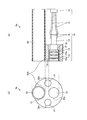
- FIG. 2 is (a) a front view of the distal end portion of the endoscope according to Embodiment 1 of the present invention, and (b) a cross-sectional view in a vertical plane including the optical axis.
- FIG. 3 is a front view of a distal end portion of the endoscope according to the first modification of the first embodiment of the present invention.
- FIG. 4 is a front view of a distal end portion of the endoscope according to the second modification of the first embodiment of the present invention.
- FIG. 1 is a diagram schematically illustrating an entire configuration of an endoscope system according to Embodiment 1 of the present invention.
- FIG. 2 is (a) a front view of the distal end portion of the endoscope according to Embodiment 1 of the present invention, and (b) a cross-sectional view in a vertical plane including the optical axi
- FIG. 5 is (a) a front view of a distal end portion of the endoscope according to the second embodiment of the present invention, and (b) a cross-sectional view in a vertical plane including an optical axis.
- FIG. 6 is a cross-sectional view orthogonal to the optical axis of a distal end portion of an endoscope according to a modification of the second embodiment of the present invention.
- FIG. 7 is (a) a front view of a distal end portion of an endoscope according to Embodiment 3 of the present invention, and (b) a cross-sectional view in a vertical plane including an optical axis.
- FIG. 8 is (a) a front view of a distal end portion of an endoscope according to Embodiment 4 of the present invention, and (b) a cross-sectional view in a vertical plane including an optical axis.
- an endoscope system including an endoscope end portion will be described. Further, the present invention is not limited by the embodiment. Further, each of the drawings referred to in the following description merely schematically shows the shape, size, and positional relationship to the extent that the contents of the present invention can be understood. That is, the present invention is not limited to only the shapes, sizes, and positional relationships illustrated in each drawing. Furthermore, the drawings include portions having different dimensions and ratios between the drawings.
- FIG. 1 is a diagram schematically illustrating an entire configuration of an endoscope system 1 according to the first embodiment of the present invention.
- an endoscope system 1 includes an endoscope 2 that is introduced into a subject and captures an image of the inside of the subject to generate an image signal in the subject.
- An information processing device 3 that performs predetermined image processing on an image signal captured by the endoscope 2 and controls each unit of the endoscope system 1; a light source device 4 that generates illumination light for the endoscope 2;
- a display device 5 that displays an image signal after image processing by the device 3.
- the endoscope 2 includes an insertion portion 6 to be inserted into the subject, an operation portion 7 on the proximal end side of the insertion portion 6 which is gripped by an operator, and a flexible universal extending from the operation portion 7.
- Code 8
- the insertion section 6 is realized using a light guide made of an illumination fiber, an electric cable, an optical fiber, or the like.
- the insertion portion 6 has a distal end portion 6a having a built-in imaging device, a bendable bending portion 6b formed by a plurality of bending pieces, and flexibility provided on a base end side of the bending portion 6b. And a flexible tube portion 6c.
- the distal end portion 6a is provided with an imaging unit 10 which is an observation unit for imaging the inside of the subject, a treatment tool channel 20 through which a treatment tool is inserted, and a light guide 21 which illuminates the inside of the subject via an illumination lens. (See FIG. 2).
- the operation unit 7 includes a bending knob 7a that bends the bending unit 6b in the up-down direction and the left-right direction, a treatment tool insertion unit 7b into which a treatment tool such as a biological forceps or a laser scalpel is inserted into a body cavity of a subject, and an information processing device. 3, a plurality of switches 7c for operating peripheral devices such as the light source device 4.
- the treatment tool inserted from the treatment tool insertion portion 7b is exposed through an opening at the distal end of the insertion portion 6 through the treatment tool channel 20 provided therein.
- the universal cord 8 is configured using a light guide 21 made of an illumination fiber, a cable, and the like.
- the universal cord 8 is branched at a base end, and one branched end is a connector 8a, and the other base end is a connector 8b.
- the connector 8a is detachable from the connector of the information processing device 3.
- the connector 8b is detachable from the light source device 4.
- the universal cord 8 transmits the illumination light emitted from the light source device 4 to the distal end portion 6a via the connector 8b and the light guide 21 composed of the illumination fiber.
- the universal code 8 transmits an image signal captured by an imaging device described later to the information processing device 3 via a cable and a connector 8a.
- the information processing device 3 performs predetermined image processing on the image signal output from the connector 8a, and controls the entire endoscope system 1.
- the light source device 4 is configured using a light source that emits light, a condenser lens, and the like.
- the light source device 4 emits light from the light source under the control of the information processing device 3, and transmits the light to the endoscope 2 connected via the connector 8 b and the light guide 21 composed of the illumination fiber of the universal cord 8. It is supplied as illumination light for a certain subject.
- the display device 5 is configured using a display using liquid crystal or organic EL (Electro Luminescence).
- the display device 5 displays various types of information including an image that has been subjected to predetermined image processing by the information processing device 3 via the video cable 5a. Accordingly, the operator can observe the image (in-vivo image) displayed on the display device 5 and operate the endoscope 2 to observe a desired position in the subject and determine a symptom.
- FIG. 2 is (a) a front view of the distal end portion 6a of the endoscope 2 according to Embodiment 1 of the present invention, and (b) a cross-sectional view in a vertical plane including the optical axis.
- the imaging unit 10 includes a lens unit 11, an imaging device 12 disposed on the base end side of the lens unit 11, a circuit board 13 connected to an end surface of the imaging device 12 on the base end side, and a plurality of signal cables 15. And a collective cable 14 in which is twisted.
- the lens unit 11 has a plurality of objective lenses 11a, 11b, and 11c, and a lens holder 11d that holds the cover glass 17.
- the image sensor 12 is composed of a CCD or a CMOS, and the light receiving portion of the image sensor 12 is covered with a cover glass 17 and adhered thereto.
- the imaging device 12 is held by a lens holder 11d via a cover glass 17 adhered to the imaging device 12.
- the circuit board 13 is electrically and mechanically connected to a connection terminal (not shown) formed on the back side of the image sensor 12.
- a connection terminal (not shown) formed on the back side of the image sensor 12.
- the core wire 16 is connected.
- the treatment instrument channel 20 is made of a tube made of polytetrafluoroethylene (PTFE) and having a circular cross-sectional inner diameter.
- the treatment tool channel 20 made of PTFE is preferably one whose outer periphery is surface-treated in order to improve adhesiveness to a partition member 30 described later.
- the partition member 30 holds the imaging unit 10, the treatment tool channel 20, and the two light guides 21 therein, and adjusts the positions of the imaging unit 10, the treatment tool channel 20, and the two light guides 21.
- the partition member 30 has a columnar shape, and has grooves 31, 32, and 33 on the outer periphery thereof, which penetrate the inside of the partition member 30 in parallel with the optical axis direction.
- the treatment instrument channel 20 is fitted into the groove 31, and the outer surface of the treatment instrument channel 20 protruding from the groove 31 is exposed from the outer surface of the partition member 30.
- the light guides 21 are fitted into the grooves 32, respectively, and the outer surfaces of the light guides 21 protruding from the grooves 32 are exposed from the outer surfaces of the partition members 30.
- the imaging unit 10 is fitted into the groove 33, and the outer surface of the imaging unit 10 protruding from the groove 33 is exposed from the outer surface of the partition member 30.
- each of the grooves 31, 32, and 33 is substantially the same as the size of the built-in component to be fitted, and is large enough to fix the built-in product to be fitted, that is, at least one-third of the outer circumference of the built-in product to be fitted. It is preferable that the size is in contact with two or more, but if the position of each built-in component can be adjusted, the length of contact may be smaller than ⁇ ⁇ of the outer circumference of the built-in component.
- the sizes of the grooves 31, 32, and 33 are smaller than 1 / of the outer circumference of the member to be fitted, the members may be fixed to the grooves 31, 32, and 33 with an adhesive. .
- the partition member 30 has a smaller diameter than a conventionally used distal end structural member, and the treatment tool channel 20, the light guide 21, and the imaging unit 10 are disposed on the outer periphery of the partition member 30.
- the position is adjusted by being fitted into the arranged grooves 31, 32, 33. Therefore, in the first embodiment of the present invention, the diameter of the distal end portion 6a of the endoscope 2 can be reduced, and the positional accuracy of the built-in object housed in the distal end portion can be improved.
- the grooves 31, 32, and 33 are arranged for the purpose of exposing all the internal components from the outer surface of the partition member 30, but at least one of the internal components is located on the outer surface.
- the grooves 31, 32, and 33 are arranged for the purpose of exposing, the diameter of the distal end portion 6a of the endoscope 2 can be reduced.
- FIG. 3 is a front view of the distal end portion 6a of the endoscope 2 according to the first modification of the first embodiment of the present invention.
- the partition member 30A has through holes 32A and 33A instead of the grooves 32 and 33.
- the treatment instrument channel 20 is fitted into the groove 31, and the outer surface of the treatment instrument channel 20 protruding from the groove 31 is exposed from the outer surface of the partition member 30 ⁇ / b> A.
- the light guide 21 is inserted through the through hole 32B, and the imaging unit 10 is inserted through the through hole 33A.
- at least one of the internal components, preferably the treatment instrument channel 20, which is the internal component having the largest diameter, is exposed from the outer surface of the partition member 30A, so that the distal end portion 6a is thinned. The diameter can be increased.
- the endoscope having the imaging unit 10, the treatment tool channel 20, and the light guide 21 as a built-in object has been described as an example.
- the present invention is not limited to this.
- the built-in component is held and fixed to the partition member, and at least one built-in component is located outside the partition member. By exposing from the surface, the distal end portion 6a can be reduced in diameter.
- FIG. 4 is a front view of the distal end portion 6a of the endoscope 2 according to the second modification of the first embodiment of the present invention.
- the built-in components are the imaging unit 10 and the light guide 21.
- the partition member 30B has a groove 33 and a through hole 32B.
- the imaging unit 10 is fitted into the groove 33, and the outer surface of the imaging unit 10 that protrudes from the groove 33 is exposed from the outer surface of the partition member 30B.
- the light guides 21 are inserted through the through holes 32B.
- at least one of the built-in components, preferably the imaging unit 10 having the largest diameter, is exposed from the outer surface of the partition member 30B so that the distal end portion 6a has a small diameter.
- FIG. 5 is (a) a front view of the distal end portion 6a of the endoscope 2 according to Embodiment 2 of the present invention, and (b) a cross-sectional view in a vertical plane including the optical axis.
- the distal end portion 6a of the endoscope 2 has the treatment tool channel 20, the light guide 21, and the imaging unit 10 fitted into grooves 31, 32, and 33 formed on the outer periphery of the partition member 30, respectively.
- the treatment tool channel 20 exposed from the outer surface of the partition member 30 and the outer surface of the partition member 30, the light guide 21, and the resin coating layer 40 that covers the imaging unit 10 are provided.
- the partition member 30 and the resin coating layer 40 have a length that covers at least the lens unit 11 and the imaging element 12 which are the front ends of the imaging unit 10.
- the resin coating layer 40 can be formed by disposing the tip 6a in a mold for resin molding, injecting resin between the mold and the tip 6a, and curing the resin.
- the imaging element 12 since the imaging element 12 is covered with the conductive resin coating layer 40, it is necessary to shield electromagnetic noise from the imaging element 12 from the outside and electromagnetic noise from the imaging element 12 to the outside. Can be. Of course, a short circuit is prevented by the conductive resin coating layer 40 by providing an insulating film on a surface of an electric terminal or the like on the surface of the imaging element 12. In addition, since the strength of the distal end portion 6a can be improved by the resin coating layer 40, it is possible to prevent the imaging element 12 from being damaged.
- FIG. 6 is a cross-sectional view orthogonal to the optical axis of distal end portion 6a of endoscope 2 according to a modification of the second embodiment of the present invention.
- the resin coating layer 40 ⁇ / b> D covers the outer surface of the partition member 30 and the partition member 30 from the lens unit 11 of the imaging unit 10 to the end of the jacket 18 of the collective cable 14. Covers the treatment tool channel 20, the light guide 21, and the imaging unit 10 exposed from the outer surface of the imaging device.
- the inside of the distal end portion 6a of the endoscope 2 is sealed with a sealing resin for the purpose of improving the reliability of the connection portion of the signal cable 15 and the connection portion of the imaging element 12 and the circuit board.
- a sealing resin for the purpose of improving the reliability of the connection portion of the signal cable 15 and the connection portion of the imaging element 12 and the circuit board.
- FIG. 7 is (a) a front view of the distal end portion 6a of the endoscope 2 according to Embodiment 3 of the present invention, and (b) a cross-sectional view in a vertical plane including the optical axis.
- the treatment instrument channel 20, the light guide 21, and the imaging unit 10 are fitted into grooves 31, 32, and 33 formed on the outer periphery of the partition member 30 at the distal end 6a of the endoscope 2.
- a metal coating layer 50 covering the outer surface of the partition member 30 and the treatment instrument channel 20, the light guide 21, and the imaging unit 10 exposed from the outer surface of the partition member 30. It is preferable that the partition member 30 and the metal coating layer 50 have a length that covers at least the lens unit 11 and the imaging element 12 which are the front ends of the imaging unit 10.
- the metal coating layer 50 can be formed by electrolytic plating or the like after forming a metal seed layer on the partition member 30, the treatment instrument channel, the light guide 21, and the outer surface of the imaging unit 10.
- the imaging element 12 since the imaging element 12 is covered with the metal coating layer 50, electromagnetic noise from the outside to the imaging element 12 and electromagnetic noise from the imaging element 12 to the outside can be shielded. Further, since the strength of the distal end portion 6a can be improved by the metal coating layer 50, it is possible to prevent the imaging element 12 from being damaged.
- the distal end portion 6a of the endoscope 2 according to Embodiment 4 includes a resin coating layer and a metal coating layer that cover the outer surface of the partition member.
- FIG. 8 is (a) a front view of the distal end portion 6a of the endoscope 2 according to Embodiment 4 of the present invention, and (b) a cross-sectional view in a vertical plane including the optical axis.
- the treatment tool channel 20, the light guide 21, and the imaging unit 10 are fitted into grooves 31, 32, and 33 formed on the outer periphery of the partition member 30 at the distal end 6a of the endoscope 2.
- the partition member 30, the resin coating layer 40, and the metal coating layer 50 have a length that covers at least the lens unit 11 and the imaging element 12, which are the front ends of the imaging unit 10.
- the imaging element 12 since the imaging element 12 is covered with the resin coating layer 40 and the metal coating layer 50, electromagnetic noise from the external to the imaging element 12 and electromagnetic noise from the imaging element 12 to the outside are shielded. Properties can be further improved. Further, since the strength of the distal end portion 6a can be improved by the resin coating layer 40 and the metal coating layer 50, it is possible to prevent the imaging element 12 from being damaged.
Landscapes
- Health & Medical Sciences (AREA)
- Life Sciences & Earth Sciences (AREA)
- Surgery (AREA)
- Nuclear Medicine, Radiotherapy & Molecular Imaging (AREA)
- Biomedical Technology (AREA)
- Optics & Photonics (AREA)
- Pathology (AREA)
- Radiology & Medical Imaging (AREA)
- Biophysics (AREA)
- Engineering & Computer Science (AREA)
- Physics & Mathematics (AREA)
- Heart & Thoracic Surgery (AREA)
- Medical Informatics (AREA)
- Molecular Biology (AREA)
- Animal Behavior & Ethology (AREA)
- General Health & Medical Sciences (AREA)
- Public Health (AREA)
- Veterinary Medicine (AREA)
- Endoscopes (AREA)
Abstract
内視鏡に使用される各内蔵物の位置を精度よく調整するとともに、内視鏡先端部の細径化を可能とする内視鏡先端構造を提供する。本発明の内視鏡先端構造は、照明光を照射するライトガイド21と、前記照明光で照明された被写体を撮像する撮像ユニット10と、ライトガイド21および撮像ユニット10の先端部を内部に保持して、ライトガイド21および撮像ユニット10の位置を調整する仕切り部材30と、を備え、ライトガイド21および撮像ユニット10のうちの少なくとも1つは、仕切り部材30の外表面から露出していることを特徴とする。
Description
本発明は、小型化可能な内視鏡先端構造および内視鏡に関する。
従来、内視鏡は、先端に撮像装置が設けられた細長形状をなす可撓性の挿入部を患者等の被検体内に挿入することによって、被検体内の体内画像を取得する。このような内視鏡先端部において、画像を取得する撮像ユニット、光を照射するライトガイド、および処置具を通すチャンネルといった内蔵物は、先端構成部品に設けられた収納孔にそれぞれ挿入することにより、各内蔵物の位置が調整されている(例えば、特許文献1を参照)。
しかしながら、上述した特許文献1等の先端構造部品は、各内蔵物を収納孔に挿入することによって保持、固定するため、先端構造部品の外径を小さくするには限界があった。
本発明は、上記に鑑みてなされたものであって、内視鏡に使用される各内蔵物の位置を精度よく調整するとともに、内視鏡先端部の細径化を可能とする内視鏡先端構造を提供することを目的とする。
上述した課題を解決し、目的を達成するために、本発明に係る内視鏡先端構造は、照明光を照射するライトガイドと、前記照明光で照明された被写体を撮像する撮像ユニットと、前記ライトガイドおよび前記撮像ユニットの先端部を内部に保持して、前記ライトガイドおよび前記撮像ユニットの位置を調整する仕切り部材と、を備え、前記ライトガイドおよび前記撮像ユニットのうちの少なくとも1つは、前記仕切り部材の外表面から露出していることを特徴とする。
また、本発明に係る内視鏡先端構造は、上記発明において、送気・送水ノズル、または処置具を挿通するチャンネルを、さらに備え、前記仕切り部材は、前記ライトガイド、前記撮像ユニットおよび前記チャンネルの先端部を内部に保持して、前記ライトガイド、前記撮像ユニットおよび前記チャンネルの位置を調整し、前記ライトガイド、前記撮像ユニットおよび前記チャンネルのうちの少なくとも1つは、前記仕切り部材の外表面から露出していることを特徴とする。
また、本発明に係る内視鏡先端構造は、上記発明において、前記仕切り部材は、前記ライトガイド、前記撮像ユニットおよび前記チャンネルの先端部をそれぞれ配置する溝部を有し、前記ライトガイド、前記撮像ユニットおよび前記チャンネルの先端部のそれぞれの一部が、前記仕切り部材の外表面から露出していることを特徴とする。
また、本発明に係る内視鏡先端構造は、上記発明において、前記仕切り部材の外表面、ならびに前記仕切り部材の外表面から露出する前記ライトガイド、前記撮像ユニットおよび前記チャンネルを被覆する樹脂被覆層を備えることを特徴する。
また、本発明に係る内視鏡先端構造は、上記発明において、前記仕切り部材の外表面、ならびに前記仕切り部材の外表面から露出する前記ライトガイド、前記撮像ユニットおよび前記チャンネルを被覆する金属被覆層を備えることを特徴する。
また、本発明に係る内視鏡先端構造は、上記発明において、前記樹脂被覆層の外表面を覆う金属被覆層を備えることを特徴する。
また、本発明に係る内視鏡は、上記のいずれか一つに記載の内視鏡先端構造を備えたことを特徴とする。
本発明によれば、内視鏡の先端部を細径化できるとともに、先端部に収容される内蔵物の位置精度を向上することができるという効果を奏する。
以下、本発明を実施するための形態(以下、「実施の形態」という)として、内視鏡先端部を備えた内視鏡システムについて説明する。また、この実施の形態により本発明が限定されるものではない。さらに、以下の説明において参照する各図は、本発明の内容を理解でき得る程度に形状、大きさ、および位置関係を概略的に示してあるに過ぎない。すなわち、本発明は、各図で例示された形状、大きさおよび位置関係のみに限定されるものではない。さらにまた、図面の相互間においても、互いの寸法や比率が異なる部分が含まれている。
(実施の形態1)
図1は、本発明の実施の形態1にかかる内視鏡システム1の全体構成を模式的に示す図である。図1に示すように、本実施の形態にかかる内視鏡システム1は、被検体内に導入され、被検体の体内を撮像して被検体内の画像信号を生成する内視鏡2と、内視鏡2が撮像した画像信号に所定の画像処理を施すとともに内視鏡システム1の各部を制御する情報処理装置3と、内視鏡2の照明光を生成する光源装置4と、情報処理装置3による画像処理後の画像信号を画像表示する表示装置5と、を備える。
図1は、本発明の実施の形態1にかかる内視鏡システム1の全体構成を模式的に示す図である。図1に示すように、本実施の形態にかかる内視鏡システム1は、被検体内に導入され、被検体の体内を撮像して被検体内の画像信号を生成する内視鏡2と、内視鏡2が撮像した画像信号に所定の画像処理を施すとともに内視鏡システム1の各部を制御する情報処理装置3と、内視鏡2の照明光を生成する光源装置4と、情報処理装置3による画像処理後の画像信号を画像表示する表示装置5と、を備える。
内視鏡2は、被検体内に挿入される挿入部6と、挿入部6の基端部側であって術者が把持する操作部7と、操作部7から延伸する可撓性のユニバーサルコード8と、を備える。
挿入部6は、照明ファイバからなるライトガイド、電気ケーブルまたは光ファイバ等を用いて実現される。挿入部6は、後述する撮像装置を内蔵した先端部6aと、複数の湾曲駒によって構成された湾曲自在な湾曲部6bと、湾曲部6bの基端部側に設けられた可撓性を有する可撓管部6cと、を有する。先端部6aには、被検体内を撮像する観察部である撮像ユニット10、処置具を挿通する処置具用チャンネル20、照明レンズを経由して被検体内を照明するライトガイド21が設けられている(図2参照)。
操作部7は、湾曲部6bを上下方向および左右方向に湾曲させる湾曲ノブ7aと、被検体の体腔内に生体鉗子、レーザメス等の処置具が挿入される処置具挿入部7bと、情報処理装置3、光源装置4等の周辺機器の操作を行う複数のスイッチ部7cと、を有する。処置具挿入部7bから挿入された処置具は、内部に設けられた処置具用チャンネル20を経て挿入部6先端の開口部から表出する。
ユニバーサルコード8は、照明ファイバからなるライトガイド21、ケーブル等を用いて構成される。ユニバーサルコード8は、基端で分岐しており、分岐した一方の端部がコネクタ8aであり、他方の基端がコネクタ8bである。コネクタ8aは、情報処理装置3のコネクタに対して着脱自在である。コネクタ8bは、光源装置4に対して着脱自在である。ユニバーサルコード8は、光源装置4から出射された照明光を、コネクタ8b、および照明ファイバからなるライトガイド21を経由して先端部6aに伝播する。また、ユニバーサルコード8は、後述する撮像装置が撮像した画像信号を、ケーブルおよびコネクタ8aを経由して情報処理装置3に伝送する。
情報処理装置3は、コネクタ8aから出力される画像信号に所定の画像処理を施すとともに、内視鏡システム1全体を制御する。
光源装置4は、光を発する光源や、集光レンズ等を用いて構成される。光源装置4は、情報処理装置3の制御のもと、光源から光を発し、コネクタ8bおよびユニバーサルコード8の照明ファイバからなるライトガイド21を経由して接続された内視鏡2へ、被写体である被検体内に対する照明光として供給する。
表示装置5は、液晶または有機EL(Electro Luminescence)を用いた表示ディスプレイ等を用いて構成される。表示装置5は、映像ケーブル5aを経由して情報処理装置3によって所定の画像処理が施された画像を含む各種情報を表示する。これにより、術者は、表示装置5が表示する画像(体内画像)を見ながら内視鏡2を操作することにより、被検体内の所望の位置の観察および症状を判定することができる。
次に、内視鏡2の先端部6aについて詳細に説明する。図2は、本発明の実施の形態1に係る内視鏡2の先端部6aの(a)正面図、および(b)光軸を含む鉛直面での断面図である。
撮像ユニット10は、レンズユニット11と、レンズユニット11の基端側に配置する撮像素子12と、撮像素子12の基端側の面に端面接続されている回路基板13と、複数の信号ケーブル15を撚り合せた集合ケーブル14と、を有する。
レンズユニット11は、複数の対物レンズ11a、11b、および11cと、カバーガラス17を保持するレンズホルダ11dを有する。
撮像素子12は、CCDまたはCMOSなどから構成され、撮像素子12の受光部は、カバーガラス17により覆われて接着されている。撮像素子12は、撮像素子12に接着されたカバーガラス17を経由してレンズホルダ11dで保持されている。
回路基板13は、撮像素子12の裏面側に形成されている図示しない接続端子に電気的および機械的に接続されている。回路基板13上には、撮像素子12に電源を供給、あるいは情報処理装置3からの信号を撮像素子12へ入力または撮像素子12からの信号を情報処理装置3に出力する複数の信号ケーブル15の芯線16が接続されている。
処置具チャンネル20は、ポリテトラフルオロエチレン(PTFE)製の断面内径形状が円形のチューブから構成されている。PTFE製の処置具チャンネル20は、後述する仕切り部材30との接着性を向上するために、外周を表面処理したものであることが好ましい。
仕切り部材30は、撮像ユニット10、処置具チャンネル20、および2本のライトガイド21を内部に保持して、撮像ユニット10、処置具チャンネル20、および2本のライトガイド21の位置を調整する。
仕切り部材30は、円柱状をなし、外周上に、光軸方向と平行に仕切り部材30の内部を貫通する溝部31、32、33を有している。溝部31には処置具チャンネル20が嵌めこまれ、溝部31からはみ出した処置具チャンネル20の外表面は、仕切り部材30の外表面から露出している。また、溝部32にはライトガイド21がそれぞれ嵌めこまれ、溝部32からはみ出したライトガイド21の外表面は、仕切り部材30の外表面から露出している。溝部33には撮像ユニット10が嵌めこまれ、溝部33からはみ出した撮像ユニット10の外表面は、仕切り部材30の外表面から露出している。
溝部31、32、および33の大きさ(および形状)は、嵌め合せる内蔵物と略同径であって、嵌め合せる内蔵物を固定できる大きさ、すなわち、嵌め合せる内蔵物の外周の少なくとも1/2以上と接する大きさであることが好ましいが、各内蔵物の位置の調整が可能であれば、接する長さが内蔵物の外周の1/2よりも小さくてもよい。溝部31、32、および33の大きさが、嵌め合せる部材の外周の1/2よりも小さい接する大きさである場合は、各部材を接着剤により溝部31、32、および33に固定すればよい。
本発明の実施の形態1では、仕切り部材30は従来使用する先端構造部材よりも細径なものを使用し、処置具チャンネル20、ライトガイド21および撮像ユニット10は、仕切り部材30の外周上に配置された溝部31、32、33に嵌めこまれて、位置の調整がされている。したがって、本発明の実施の形態1では、内視鏡2の先端部6aを細径化するとともに、先端部に収容される内蔵物の位置精度を向上することができる。
なお、本発明の実施の形態1では、すべての内蔵物が仕切り部材30の外表面から露出するという目的で溝部31、32、33が配置されているが、内蔵物の少なくとも1つが外表面から露出するという目的で溝部を形成、配置することにより、内視鏡2の先端部6aを細径化することができる。図3は、本発明の実施の形態1の変形例1に係る内視鏡2の先端部6aの正面図である。
実施の形態1の変形例1において、仕切り部材30Aは、溝部32および33に換えて、貫通孔32A、33Aを有している。溝部31には処置具チャンネル20が嵌めこまれ、溝部31からはみ出した処置具チャンネル20の外表面は、仕切り部材30Aの外表面から露出している。貫通孔32Bにはライトガイド21がそれぞれ挿通され、貫通孔33Aには撮像ユニット10が挿通されている。実施の形態1の変形例1のように、内蔵物の少なくとも1つ、好ましくは最大径の内蔵物である処置具チャンネル20を仕切り部材30Aの外表面から露出させることにより、先端部6aを細径化することができる。
また、上記実施の形態1では、撮像ユニット10、処置具チャンネル20およびライトガイド21を内蔵物として有する内視鏡を例として説明したが、これに限定するものではなく、処置具チャンネル20に換えて送気・送水ノズルを有するものや、処置具チャンネルと送気・送水ノズルをともに有する内視鏡においても、内蔵物が仕切り部材に保持、固定され、少なくとも1つの内蔵物が仕切り部材の外表面から露出させることで、先端部6aを細径化することができる。
さらに、内蔵物が、撮像ユニット10およびライトガイド21のみの場合でも、撮像ユニット10およびライトガイド21のうちの少なくとも1つが、仕切り部材の外表面から露出することによって、先端部6aを細径化することができる。図4は、本発明の実施の形態1の変形例2に係る内視鏡2の先端部6aの正面図である。
実施の形態1の変形例2において、内蔵物は撮像ユニット10およびライトガイド21である。仕切り部材30Bは、溝部33と、貫通孔32Bを有している。溝部33には撮像ユニット10が嵌めこまれ、溝部33からはみ出した撮像ユニット10の外表面は、仕切り部材30Bの外表面から露出している。貫通孔32Bにはライトガイド21がそれぞれ挿通されている。実施の形態1の変形例2のように、内蔵物の少なくとも1つ、好ましくは最大径の内蔵物である撮像ユニット10を仕切り部材30Bの外表面から露出させることにより、先端部6aを細径化することができる。
(実施の形態2)
実施の形態2に係る内視鏡2の先端部6aは、仕切り部材の外表面を被覆する樹脂被覆層を備える。図5は、本発明の実施の形態2に係る内視鏡2の先端部6aの(a)正面図、および(b)光軸を含む鉛直面での断面図である。
実施の形態2に係る内視鏡2の先端部6aは、仕切り部材の外表面を被覆する樹脂被覆層を備える。図5は、本発明の実施の形態2に係る内視鏡2の先端部6aの(a)正面図、および(b)光軸を含む鉛直面での断面図である。
実施の形態2において、内視鏡2の先端部6aは、仕切り部材30の外周に形成された溝部31、32、および33に、処置具チャンネル20、ライトガイド21、および撮像ユニット10がそれぞれ嵌め込まれ、仕切り部材30の外表面、ならびに仕切り部材30の外表面から露出する処置具チャンネル20、ライトガイド21および撮像ユニット10を被覆する樹脂被覆層40を備える。仕切り部材30および樹脂被覆層40は、少なくとも、撮像ユニット10の前端であるレンズユニット11および撮像素子12を覆う長さとすることが好ましい。なお、樹脂被覆層40は、樹脂成型用の型内に先端部6aを配置し、型と先端部6aの間に樹脂を注入し、硬化させることにより形成することができる。
実施の形態2では、導電性の樹脂被覆層40で撮像素子12が覆われているため、外部からの撮像素子12への電磁波ノイズ、及び撮像素子12からの外部への電磁波ノイズを遮蔽することができる。もちろん、撮像素子12の表面にある電気的な端子等の面には絶縁膜を設けるなどして、導電性の樹脂被覆層40でショートしないようにしている。また、樹脂被覆層40により先端部6aの強度を向上することができるので、撮像素子12の破損等を防止することができる。
なお、上記の実施の形態2では、仕切り部材30および樹脂被覆層40の光軸方向の長さを、撮像ユニット10の前端であるレンズユニット11から撮像素子12までとしているが、樹脂被覆層40で基端側まで接着固定することもできる。図6は、本発明の実施の形態2の変形例に係る内視鏡2の先端部6aの光軸と直交する断面図である。
図6に示すように、実施の形態2の変形例では、樹脂被覆層40Dは、撮像ユニット10のレンズユニット11から集合ケーブル14のジャケット18端まで、仕切り部材30の外表面、ならびに仕切り部材30の外表面から露出する処置具チャンネル20、ライトガイド21、および撮像ユニット10を被覆する。
一般に、内視鏡2の先端部6a内は、信号ケーブル15の接続部、および撮像素子12と回路基板の接続部の信頼性の向上等を目的として、封止樹脂で封止されている。実施の形態2の変形例では、樹脂被覆層40Dにより撮像素子11、回路基板13および信号ケーブル15の接続部を被覆するため、内視鏡2の先端部6a内の封止工程を省略することが可能となる。
(実施の形態3)
実施の形態3に係る内視鏡2の先端部6aは、仕切り部材の外表面を被覆する金属被覆層を備える。図7は、本発明の実施の形態3に係る内視鏡2の先端部6aの(a)正面図、および(b)光軸を含む鉛直面での断面図である。
実施の形態3に係る内視鏡2の先端部6aは、仕切り部材の外表面を被覆する金属被覆層を備える。図7は、本発明の実施の形態3に係る内視鏡2の先端部6aの(a)正面図、および(b)光軸を含む鉛直面での断面図である。
実施の形態3において、内視鏡2の先端部6aは、仕切り部材30の外周に形成された溝部31、32、および33に、処置具チャンネル20、ライトガイド21、および撮像ユニット10がそれぞれ嵌め込まれ、仕切り部材30の外表面、ならびに仕切り部材30の外表面から露出する処置具チャンネル20、ライトガイド21および撮像ユニット10を被覆する金属被覆層50を備える。仕切り部材30および金属被覆層50は、少なくとも、撮像ユニット10の前端であるレンズユニット11および撮像素子12を覆う長さとすることが好ましい。金属被覆層50は、仕切り部材30、処置具チャンネル、ライトガイド21、および撮像ユニット10の外表面に金属シード層を形成した後、電解メッキ等により形成することができる。
実施の形態3では、金属被覆層50で撮像素子12が覆われているため、外部からの撮像素子12への電磁波ノイズ、及び撮像素子12からの外部への電磁波ノイズを遮蔽することができる。また、金属被覆層50により先端部6aの強度を向上することができるので、撮像素子12の破損等を防止することができる。
(実施の形態4)
実施の形態4に係る内視鏡2の先端部6aは、仕切り部材の外表面を被覆する、樹脂被覆層および金属被覆層を備える。図8は、本発明の実施の形態4に係る内視鏡2の先端部6aの(a)正面図、および(b)光軸を含む鉛直面での断面図である。
実施の形態4に係る内視鏡2の先端部6aは、仕切り部材の外表面を被覆する、樹脂被覆層および金属被覆層を備える。図8は、本発明の実施の形態4に係る内視鏡2の先端部6aの(a)正面図、および(b)光軸を含む鉛直面での断面図である。
実施の形態4において、内視鏡2の先端部6aは、仕切り部材30の外周に形成された溝部31、32、および33に、処置具チャンネル20、ライトガイド21、および撮像ユニット10がそれぞれ嵌め込まれ、仕切り部材30の外表面、ならびに仕切り部材30の外表面から露出する処置具チャンネル20、ライトガイド21および撮像ユニット10を被覆する樹脂被覆層40と、樹脂被覆層40を被覆する金属被覆層50を備える。仕切り部材30、樹脂被覆層40および金属被覆層50は、少なくとも、撮像ユニット10の前端であるレンズユニット11および撮像素子12を覆う長さとすることが好ましい。
実施の形態4では、樹脂被覆層40および金属被覆層50で撮像素子12が覆われているため、外部からの撮像素子12への電磁波ノイズ、及び撮像素子12からの外部への電磁波ノイズの遮蔽性をさらに向上することができる。また、樹脂被覆層40および金属被覆層50により先端部6aの強度を向上することができるので、撮像素子12の破損等を防止することができる。
1 内視鏡システム
2 内視鏡
3 情報処理装置
4 光源装置
5 表示装置
6 挿入部
6a 先端部
6b 湾曲部
6c 可撓管部
7 操作部
7a 湾曲ノブ
7b 処置具挿入部
7c スイッチ部
8 ユニバーサルコード
8a、8b コネクタ
10 撮像ユニット
11 レンズユニット
11a、11b、11c 対物レンズ
11d レンズホルダ
12 撮像素子
13 回路基板
14 集合ケーブル
15 信号ケーブル
16 芯線
17 カバーガラス
20 処置具チャンネル
21 ライトガイド
30 仕切り部材
31、32、33 溝部
40 樹脂被覆層
50 金属被覆層
2 内視鏡
3 情報処理装置
4 光源装置
5 表示装置
6 挿入部
6a 先端部
6b 湾曲部
6c 可撓管部
7 操作部
7a 湾曲ノブ
7b 処置具挿入部
7c スイッチ部
8 ユニバーサルコード
8a、8b コネクタ
10 撮像ユニット
11 レンズユニット
11a、11b、11c 対物レンズ
11d レンズホルダ
12 撮像素子
13 回路基板
14 集合ケーブル
15 信号ケーブル
16 芯線
17 カバーガラス
20 処置具チャンネル
21 ライトガイド
30 仕切り部材
31、32、33 溝部
40 樹脂被覆層
50 金属被覆層
Claims (7)
- 照明光を照射するライトガイドと、
前記照明光で照明された被写体を撮像する撮像ユニットと、
前記ライトガイドおよび前記撮像ユニットの先端部を内部に保持して、前記ライトガイドおよび前記撮像ユニットの位置を調整する仕切り部材と、
を備え、
前記ライトガイドおよび前記撮像ユニットのうちの少なくとも1つは、前記仕切り部材の外表面から露出していることを特徴とする内視鏡先端構造。 - 送気・送水ノズル、または処置具を挿通するチャンネルを、さらに備え、
前記仕切り部材は、前記ライトガイド、前記撮像ユニットおよび前記チャンネルの先端部を内部に保持して、前記ライトガイド、前記撮像ユニットおよび前記チャンネルの位置を調整し、
前記ライトガイド、前記撮像ユニットおよび前記チャンネルのうちの少なくとも1つは、前記仕切り部材の外表面から露出していることを特徴とする請求項1に記載の内視鏡先端構造。 - 前記仕切り部材は、前記ライトガイド、前記撮像ユニットおよび前記チャンネルの先端部をそれぞれ配置する溝部を有し、
前記ライトガイド、前記撮像ユニットおよび前記チャンネルの先端部のそれぞれの一部が、前記仕切り部材の外表面から露出していることを特徴とする請求項2に記載の内視鏡先端構造。 - 前記仕切り部材の外表面、ならびに前記仕切り部材の外表面から露出する前記ライトガイド、前記撮像ユニットおよび前記チャンネルを被覆する樹脂被覆層を備えることを特徴する請求項2または3に記載の内視鏡先端構造。
- 前記仕切り部材の外表面、ならびに前記仕切り部材の外表面から露出する前記ライトガイド、前記撮像ユニットおよび前記チャンネルを被覆する金属被覆層を備えることを特徴する請求項2または3に記載の内視鏡先端構造。
- 前記樹脂被覆層の外表面を覆う金属被覆層を備えることを特徴する請求項4に記載の内視鏡先端構造。
- 請求項1~6のいずれか一つに記載の内視鏡先端構造を備えたことを特徴とする内視鏡。
Priority Applications (1)
| Application Number | Priority Date | Filing Date | Title |
|---|---|---|---|
| PCT/JP2018/024737 WO2020003474A1 (ja) | 2018-06-28 | 2018-06-28 | 内視鏡先端構造および内視鏡 |
Applications Claiming Priority (1)
| Application Number | Priority Date | Filing Date | Title |
|---|---|---|---|
| PCT/JP2018/024737 WO2020003474A1 (ja) | 2018-06-28 | 2018-06-28 | 内視鏡先端構造および内視鏡 |
Publications (1)
| Publication Number | Publication Date |
|---|---|
| WO2020003474A1 true WO2020003474A1 (ja) | 2020-01-02 |
Family
ID=68984954
Family Applications (1)
| Application Number | Title | Priority Date | Filing Date |
|---|---|---|---|
| PCT/JP2018/024737 Ceased WO2020003474A1 (ja) | 2018-06-28 | 2018-06-28 | 内視鏡先端構造および内視鏡 |
Country Status (1)
| Country | Link |
|---|---|
| WO (1) | WO2020003474A1 (ja) |
Citations (3)
| Publication number | Priority date | Publication date | Assignee | Title |
|---|---|---|---|---|
| JP2001083436A (ja) * | 1999-09-14 | 2001-03-30 | Fuji Photo Optical Co Ltd | 内視鏡の挿入部 |
| WO2014208218A1 (ja) * | 2013-06-25 | 2014-12-31 | オリンパスメディカルシステムズ株式会社 | 内視鏡 |
| JP2015039410A (ja) * | 2013-08-20 | 2015-03-02 | オリンパスメディカルシステムズ株式会社 | 内視鏡 |
-
2018
- 2018-06-28 WO PCT/JP2018/024737 patent/WO2020003474A1/ja not_active Ceased
Patent Citations (3)
| Publication number | Priority date | Publication date | Assignee | Title |
|---|---|---|---|---|
| JP2001083436A (ja) * | 1999-09-14 | 2001-03-30 | Fuji Photo Optical Co Ltd | 内視鏡の挿入部 |
| WO2014208218A1 (ja) * | 2013-06-25 | 2014-12-31 | オリンパスメディカルシステムズ株式会社 | 内視鏡 |
| JP2015039410A (ja) * | 2013-08-20 | 2015-03-02 | オリンパスメディカルシステムズ株式会社 | 内視鏡 |
Similar Documents
| Publication | Publication Date | Title |
|---|---|---|
| CN106886089B (zh) | 内窥镜 | |
| US11125990B2 (en) | Endoscope distal end portion, endoscope, and method of manufacturing endoscope distal end portion | |
| US20180070803A1 (en) | Imaging device and endoscope system | |
| EP3050491B1 (en) | Endoscope device | |
| US12011145B2 (en) | Endoscope distal end structure and endoscope | |
| CN113271837B (zh) | 内窥镜前端构造及内窥镜 | |
| CN106886088B (zh) | 内窥镜 | |
| EP3244603A1 (en) | Imaging unit, imaging module and endoscopic system | |
| US12042131B2 (en) | Endoscope distal end portion having conductive elastically deformable member and endoscope having the distal end portion | |
| WO2018116471A1 (ja) | ケーブル構造体、実装モジュールおよび内視鏡 | |
| EP3184028A1 (en) | Connector for endoscope | |
| WO2018155066A1 (ja) | 内視鏡 | |
| CN106061360A (zh) | 摄像装置和内窥镜装置 | |
| US20210345861A1 (en) | Holding frame, endoscope distal end structure, and endoscope | |
| US11857166B2 (en) | Imaging unit and endoscope | |
| US10517465B2 (en) | Cable connection structure and endoscope apparatus | |
| CN113271835A (zh) | 内窥镜前端构造和内窥镜 | |
| US12336691B2 (en) | Distal end portion of endoscope, distal end frame, endoscope, and electric conduction confirmation method | |
| WO2020003474A1 (ja) | 内視鏡先端構造および内視鏡 | |
| JP6321917B2 (ja) | 撮像装置および電子内視鏡 | |
| WO2019026219A1 (ja) | ケーブル端部構造体、ケーブル接続構造体、および内視鏡 | |
| JPWO2017187621A1 (ja) | ケーブル接続構造、撮像装置および内視鏡 | |
| JP2021164525A (ja) | 内視鏡 | |
| JP2016174643A (ja) | 撮像装置 | |
| WO2020012566A1 (ja) | ケーブル接続構造体、内視鏡およびケーブル接続構造体の製造方法 |
Legal Events
| Date | Code | Title | Description |
|---|---|---|---|
| 121 | Ep: the epo has been informed by wipo that ep was designated in this application |
Ref document number: 18924812 Country of ref document: EP Kind code of ref document: A1 |
|
| NENP | Non-entry into the national phase |
Ref country code: DE |
|
| 122 | Ep: pct application non-entry in european phase |
Ref document number: 18924812 Country of ref document: EP Kind code of ref document: A1 |
|
| NENP | Non-entry into the national phase |
Ref country code: JP |