WO2020003498A1 - 車両用非接触給電システム - Google Patents
車両用非接触給電システム Download PDFInfo
- Publication number
- WO2020003498A1 WO2020003498A1 PCT/JP2018/024838 JP2018024838W WO2020003498A1 WO 2020003498 A1 WO2020003498 A1 WO 2020003498A1 JP 2018024838 W JP2018024838 W JP 2018024838W WO 2020003498 A1 WO2020003498 A1 WO 2020003498A1
- Authority
- WO
- WIPO (PCT)
- Prior art keywords
- power
- coil unit
- power supply
- power transmission
- transmission coil
- Prior art date
- Legal status (The legal status is an assumption and is not a legal conclusion. Google has not performed a legal analysis and makes no representation as to the accuracy of the status listed.)
- Ceased
Links
Images





Classifications
-
- B—PERFORMING OPERATIONS; TRANSPORTING
- B60—VEHICLES IN GENERAL
- B60L—PROPULSION OF ELECTRICALLY-PROPELLED VEHICLES; SUPPLYING ELECTRIC POWER FOR AUXILIARY EQUIPMENT OF ELECTRICALLY-PROPELLED VEHICLES; ELECTRODYNAMIC BRAKE SYSTEMS FOR VEHICLES IN GENERAL; MAGNETIC SUSPENSION OR LEVITATION FOR VEHICLES; MONITORING OPERATING VARIABLES OF ELECTRICALLY-PROPELLED VEHICLES; ELECTRIC SAFETY DEVICES FOR ELECTRICALLY-PROPELLED VEHICLES
- B60L53/00—Methods of charging batteries, specially adapted for electric vehicles; Charging stations or on-board charging equipment therefor; Exchange of energy storage elements in electric vehicles
- B60L53/10—Methods of charging batteries, specially adapted for electric vehicles; Charging stations or on-board charging equipment therefor; Exchange of energy storage elements in electric vehicles characterised by the energy transfer between the charging station and the vehicle
- B60L53/12—Inductive energy transfer
- B60L53/124—Detection or removal of foreign bodies
-
- B—PERFORMING OPERATIONS; TRANSPORTING
- B60—VEHICLES IN GENERAL
- B60L—PROPULSION OF ELECTRICALLY-PROPELLED VEHICLES; SUPPLYING ELECTRIC POWER FOR AUXILIARY EQUIPMENT OF ELECTRICALLY-PROPELLED VEHICLES; ELECTRODYNAMIC BRAKE SYSTEMS FOR VEHICLES IN GENERAL; MAGNETIC SUSPENSION OR LEVITATION FOR VEHICLES; MONITORING OPERATING VARIABLES OF ELECTRICALLY-PROPELLED VEHICLES; ELECTRIC SAFETY DEVICES FOR ELECTRICALLY-PROPELLED VEHICLES
- B60L53/00—Methods of charging batteries, specially adapted for electric vehicles; Charging stations or on-board charging equipment therefor; Exchange of energy storage elements in electric vehicles
- B60L53/10—Methods of charging batteries, specially adapted for electric vehicles; Charging stations or on-board charging equipment therefor; Exchange of energy storage elements in electric vehicles characterised by the energy transfer between the charging station and the vehicle
- B60L53/12—Inductive energy transfer
- B60L53/122—Circuits or methods for driving the primary coil, e.g. supplying electric power to the coil
-
- B—PERFORMING OPERATIONS; TRANSPORTING
- B60—VEHICLES IN GENERAL
- B60L—PROPULSION OF ELECTRICALLY-PROPELLED VEHICLES; SUPPLYING ELECTRIC POWER FOR AUXILIARY EQUIPMENT OF ELECTRICALLY-PROPELLED VEHICLES; ELECTRODYNAMIC BRAKE SYSTEMS FOR VEHICLES IN GENERAL; MAGNETIC SUSPENSION OR LEVITATION FOR VEHICLES; MONITORING OPERATING VARIABLES OF ELECTRICALLY-PROPELLED VEHICLES; ELECTRIC SAFETY DEVICES FOR ELECTRICALLY-PROPELLED VEHICLES
- B60L53/00—Methods of charging batteries, specially adapted for electric vehicles; Charging stations or on-board charging equipment therefor; Exchange of energy storage elements in electric vehicles
- B60L53/30—Constructional details of charging stations
- B60L53/35—Means for automatic or assisted adjustment of the relative position of charging devices and vehicles
- B60L53/38—Means for automatic or assisted adjustment of the relative position of charging devices and vehicles specially adapted for charging by inductive energy transfer
- B60L53/39—Means for automatic or assisted adjustment of the relative position of charging devices and vehicles specially adapted for charging by inductive energy transfer with position-responsive activation of primary coils
-
- H—ELECTRICITY
- H02—GENERATION; CONVERSION OR DISTRIBUTION OF ELECTRIC POWER
- H02J—ELECTRIC POWER NETWORKS; CIRCUIT ARRANGEMENTS OR SYSTEMS FOR SUPPLYING OR DISTRIBUTING ELECTRIC POWER; SYSTEMS FOR STORING ELECTRIC ENERGY
- H02J50/00—Circuit arrangements or systems for wireless supply or distribution of electric power
- H02J50/10—Circuit arrangements or systems for wireless supply or distribution of electric power using inductive coupling
-
- H—ELECTRICITY
- H02—GENERATION; CONVERSION OR DISTRIBUTION OF ELECTRIC POWER
- H02J—ELECTRIC POWER NETWORKS; CIRCUIT ARRANGEMENTS OR SYSTEMS FOR SUPPLYING OR DISTRIBUTING ELECTRIC POWER; SYSTEMS FOR STORING ELECTRIC ENERGY
- H02J50/00—Circuit arrangements or systems for wireless supply or distribution of electric power
- H02J50/60—Circuit arrangements or systems for wireless supply or distribution of electric power responsive to the presence of foreign objects, e.g. detection of living beings
-
- H—ELECTRICITY
- H02—GENERATION; CONVERSION OR DISTRIBUTION OF ELECTRIC POWER
- H02J—ELECTRIC POWER NETWORKS; CIRCUIT ARRANGEMENTS OR SYSTEMS FOR SUPPLYING OR DISTRIBUTING ELECTRIC POWER; SYSTEMS FOR STORING ELECTRIC ENERGY
- H02J50/00—Circuit arrangements or systems for wireless supply or distribution of electric power
- H02J50/90—Circuit arrangements or systems for wireless supply or distribution of electric power involving detection or optimisation of position, e.g. alignment
-
- H—ELECTRICITY
- H02—GENERATION; CONVERSION OR DISTRIBUTION OF ELECTRIC POWER
- H02J—ELECTRIC POWER NETWORKS; CIRCUIT ARRANGEMENTS OR SYSTEMS FOR SUPPLYING OR DISTRIBUTING ELECTRIC POWER; SYSTEMS FOR STORING ELECTRIC ENERGY
- H02J2105/00—Networks for supplying or distributing electric power characterised by their spatial reach or by the load
- H02J2105/30—Networks for supplying or distributing electric power characterised by their spatial reach or by the load the load networks being external to vehicles, i.e. exchanging power with vehicles
- H02J2105/33—Networks for supplying or distributing electric power characterised by their spatial reach or by the load the load networks being external to vehicles, i.e. exchanging power with vehicles exchanging power with road vehicles
- H02J2105/37—Networks for supplying or distributing electric power characterised by their spatial reach or by the load the load networks being external to vehicles, i.e. exchanging power with vehicles exchanging power with road vehicles exchanging power with electric vehicles [EV] or with hybrid electric vehicles [HEV]
-
- Y—GENERAL TAGGING OF NEW TECHNOLOGICAL DEVELOPMENTS; GENERAL TAGGING OF CROSS-SECTIONAL TECHNOLOGIES SPANNING OVER SEVERAL SECTIONS OF THE IPC; TECHNICAL SUBJECTS COVERED BY FORMER USPC CROSS-REFERENCE ART COLLECTIONS [XRACs] AND DIGESTS
- Y02—TECHNOLOGIES OR APPLICATIONS FOR MITIGATION OR ADAPTATION AGAINST CLIMATE CHANGE
- Y02T—CLIMATE CHANGE MITIGATION TECHNOLOGIES RELATED TO TRANSPORTATION
- Y02T10/00—Road transport of goods or passengers
- Y02T10/60—Other road transportation technologies with climate change mitigation effect
- Y02T10/70—Energy storage systems for electromobility, e.g. batteries
-
- Y—GENERAL TAGGING OF NEW TECHNOLOGICAL DEVELOPMENTS; GENERAL TAGGING OF CROSS-SECTIONAL TECHNOLOGIES SPANNING OVER SEVERAL SECTIONS OF THE IPC; TECHNICAL SUBJECTS COVERED BY FORMER USPC CROSS-REFERENCE ART COLLECTIONS [XRACs] AND DIGESTS
- Y02—TECHNOLOGIES OR APPLICATIONS FOR MITIGATION OR ADAPTATION AGAINST CLIMATE CHANGE
- Y02T—CLIMATE CHANGE MITIGATION TECHNOLOGIES RELATED TO TRANSPORTATION
- Y02T10/00—Road transport of goods or passengers
- Y02T10/60—Other road transportation technologies with climate change mitigation effect
- Y02T10/7072—Electromobility specific charging systems or methods for batteries, ultracapacitors, supercapacitors or double-layer capacitors
-
- Y—GENERAL TAGGING OF NEW TECHNOLOGICAL DEVELOPMENTS; GENERAL TAGGING OF CROSS-SECTIONAL TECHNOLOGIES SPANNING OVER SEVERAL SECTIONS OF THE IPC; TECHNICAL SUBJECTS COVERED BY FORMER USPC CROSS-REFERENCE ART COLLECTIONS [XRACs] AND DIGESTS
- Y02—TECHNOLOGIES OR APPLICATIONS FOR MITIGATION OR ADAPTATION AGAINST CLIMATE CHANGE
- Y02T—CLIMATE CHANGE MITIGATION TECHNOLOGIES RELATED TO TRANSPORTATION
- Y02T90/00—Enabling technologies or technologies with a potential or indirect contribution to GHG emissions mitigation
- Y02T90/10—Technologies relating to charging of electric vehicles
- Y02T90/12—Electric charging stations
-
- Y—GENERAL TAGGING OF NEW TECHNOLOGICAL DEVELOPMENTS; GENERAL TAGGING OF CROSS-SECTIONAL TECHNOLOGIES SPANNING OVER SEVERAL SECTIONS OF THE IPC; TECHNICAL SUBJECTS COVERED BY FORMER USPC CROSS-REFERENCE ART COLLECTIONS [XRACs] AND DIGESTS
- Y02—TECHNOLOGIES OR APPLICATIONS FOR MITIGATION OR ADAPTATION AGAINST CLIMATE CHANGE
- Y02T—CLIMATE CHANGE MITIGATION TECHNOLOGIES RELATED TO TRANSPORTATION
- Y02T90/00—Enabling technologies or technologies with a potential or indirect contribution to GHG emissions mitigation
- Y02T90/10—Technologies relating to charging of electric vehicles
- Y02T90/14—Plug-in electric vehicles
Definitions
- the present invention relates to a contactless power supply system for vehicles [contactless power supply system] for vehicles.
- a non-contact power supply system In an electric vehicle (EV) or a plug-in hybrid vehicle (PHV), the mounted running battery is charged. At present, charging is generally performed by wire, but a non-contact power supply system has also been developed. In a non-contact power supply system, a battery is charged with electric power supplied from a power transmission coil unit provided in the ground or on the ground to a power receiving coil unit mounted on the lower surface of a vehicle.
- Patent Document 1 below discloses a non-contact power supply system including a power transmission coil unit.
- Patent Document 1 also discloses a foreign object detection device in a non-contact power supply system. However, even if foreign matter can be detected, power supply is affected if foreign matter is present (some systems stop power supply). Therefore, it is desired to further suppress entry of foreign matter.
- An object of the present invention is to provide a non-contact power supply system that can reduce the influence of a foreign object while suppressing the foreign object from entering.
- a feature of the present invention is to provide a non-contact pneumatic device for a vehicle including a power transmission coil unit provided on the ground side and an elevating device for moving the power transmission coil unit upward from the ground.
- the power transmission coil unit magnetically couples with the power reception coil unit provided on the vehicle side to transmit power.
- the power transmission coil unit has a case that houses the power transmission coil wound in a planar shape. On the upper surface of the case, a protruding portion protruding upward from the surrounding surface is formed around the winding central axis of the power transmission coil.
- ground-side regarding the wireless power supply system includes “on-the-ground” and “under-the-ground” and “vehicle-side”.
- ground side includes the case of “floor-side” in consideration of the case where the system is installed on an intermediate floor of a building. This “floor side” also includes the case of ““ floor surface [on the floor] ”and the case of“ under floor [under the floor] ”.
- the raised portion on the upper surface of the power receiving coil unit, it is possible to make it difficult for foreign matter to remain on the raised portion that is raised one step when power is not supplied.
- the gap is eliminated by bringing the raised portion close to (contacting with) the bottom surface of the power receiving coil unit during power supply, thereby ensuring that foreign matter enters the raised portion (that is, between the power transmitting coil unit and the power receiving coil unit). Can be suppressed.
- the power transmission coil unit that can move upward can be brought close to (close to) the power reception coil unit of the vehicle. Therefore, since the output required for power supply can be reduced, even if foreign matter enters the power transmission coil unit, the influence of the foreign matter on power supply can be reduced.
- FIG. 1 is a configuration diagram of a wireless power supply system for a vehicle according to an embodiment.
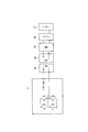
- FIG. 2 is a conceptual diagram of the configuration of the contactless power supply system.
- FIG. 3 is a sectional view of a power feeding coil unit in the non-contact power feeding system.
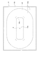
- FIG. 4 is a plan view of the power supply coil unit.
- FIG. 5 is a partial cross-sectional view of the power supply coil unit.
- FIG. 6 is a partial cross-sectional view of the power supply coil unit.
- FIG. 7 is a partial cross-sectional view of the power feeding coil unit and the power receiving coil unit.
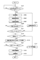
- FIG. 8 is a flowchart showing the operation of the contactless power supply system.
- the non-contact power supply system includes a power supply device 100 that is a ground-side unit and a power receiving device 200 that is a vehicle-side unit.
- the contactless power supply system wirelessly supplies power from a power supply device 100 disposed at a power supply stand or the like to a power receiving device 200 mounted on the vehicle 10 such as an EV or a PHV, and charges a battery 27 mounted on the vehicle 10. I do.
- the power supply device 100 includes the power transmission coil unit 12 disposed in a parking space near the power supply stand.
- the power receiving device 200 includes a power receiving coil unit 22 mounted on the lower surface of the vehicle 10.
- the power receiving coil unit 22 is disposed so as to face the power transmitting coil unit 12 when the vehicle 10 stops at a predetermined position (a power supplyable position) in the parking space.
- the power transmission coil 120 (see FIGS. 3 and 4) built in the power transmission coil unit 12 is configured by a primary coil made of a conductive wire, and transmits power to the power reception coil unit 22.
- the power transmission coil unit 12 will be described in more detail later.
- the power receiving coil 220 (see FIG. 7) built in the power receiving coil unit 22 is also configured by a secondary coil made of a conductive wire, and receives power from the power transmitting coil unit 12.
- electric power can be supplied from the power transmitting coil unit 12 to the power receiving coil unit 22 in a non-contact manner by electromagnetic induction between the coils 12 and 22.
- the power supply device 100 includes a power control unit [electricity controller] 11, a power transmission coil unit 12 [power transmitter transmitter unit], a wireless communication unit [wireless communication device 13], a control unit [controller] 14, and a base 15. It includes a lifting link mechanism 17, a drive motor 18, and a distance sensor 20.
- the lifting link mechanism 17 and the drive motor 18 constitute a lifting device that vertically moves the power transmission coil unit 12 upward from the ground.
- the elevating device that moves the power transmission coil unit 12 above the ground may be constituted by a rotary motor and a gear mechanism, or may be constituted by a hydraulic cylinder.
- the base 15 is buried underground, and firmly supports the lifting device from below.
- the power control unit 11 converts the AC power transmitted from the AC power supply 110 into high-frequency AC power and transmits the high-frequency AC power to the power transmission coil unit 12.
- the power control unit 11 includes a rectifier 111, a PFC circuit 112, a DC power supply 114, and an inverter 113.
- the rectifier 111 is electrically connected to the AC power supply 110 and rectifies the AC power output from the AC power supply 110.
- the PFC circuit 112 is connected between the rectifier 111 and the inverter 113, and improves the power factor by shaping the waveform output from the rectifier 111.
- the inverter 113 includes a PWM control circuit including a switching element such as an IGBT, and converts DC power into AC power based on a switching control signal to supply power to the power transmission coil unit 12.
- DC power supply 114 outputs a DC voltage for exciting power transmission coil 120.
- the wireless communication unit 13 performs two-way communication with the wireless communication unit 23 provided in the vehicle 10.
- the control unit 14 comprehensively controls the power supply device 100 and includes an inverter control unit 141, a PFC control unit 142, a sequence control unit 143, and a foreign object detection unit [foreign object detector] 144.
- the control unit 14 performs a parking position determination process when the vehicle 10 is parked in the parking space.
- a PFC (Power Factor Correction) control unit 142 generates an exciting power command
- an inverter control unit 141 controls the inverter 113 by generating a frequency command and a duty ratio of the exciting power.
- the control unit 14 transmits power for determining the parking position from the power transmission coil unit 12 to the power reception coil unit 22.
- the control unit 14 sends electric power for parking position determination by setting the power transmission coil unit 12 to weak excitation [weak excitation] (excitation weaker than during normal charging).
- the sequence control unit 143 exchanges sequence information with the power receiving device 200 via the wireless communication unit 13.
- the foreign object detection unit 144 is connected to foreign object detection coils 121 and 122 (see FIG. 3) described later, which are built in the power transmission coil unit 12.
- the foreign object detection unit 144 detects a foreign object above the first foreign object detection coil 121 based on an induced voltage generated in the first foreign object detection coil 121, and detects a second object based on the induced voltage generated in the second foreign object detection coil 122. Foreign matter above the foreign matter detection coil 122 is detected.
- the power receiving device 200 includes a power receiving coil unit 22, a wireless communication unit 23, a charge control unit [charge controller] 24, a rectifying unit 25, a relay 26, a battery 27, an inverter 28, a motor 29, A notification unit [notifier] 30.
- the charging control unit 24 controls charging of the battery 27.
- the charging control unit 24 performs a parking position determination process when the vehicle 10 is parked in a parking space.
- the charging control unit 24 monitors the power received by the power receiving coil unit 22. Further, when the power transmission coil unit 12 is excited, the charging control unit 24 detects the position of the power reception coil unit 22 with respect to the power transmission coil unit 12 (that is, the position of the vehicle 10) based on the voltage received by the power reception coil unit 22. I do.
- the charging control unit 24 also controls the wireless communication unit 23, the notification unit 30, the relay 26, and the like.
- the charging control unit 24 transmits a charging start signal to the control unit 14 of the power supply device 100 via the wireless communication unit 23.
- the rectifying unit 25 is connected to the power receiving coil unit 22, rectifies the AC power received by the power receiving coil unit 22 into DC power, and supplies the DC power to the battery 27 or the inverter 28 (see FIG. 2).
- the relay 26 is turned on / off under the control of the charging control unit 24. When the relay 26 is off, the battery 27 and the rectifier 25 are electrically disconnected (see FIG. 2). Battery 27 is a power source of vehicle 10 configured by connecting a plurality of secondary batteries.
- the inverter 28 includes a PWM control circuit including a switching element such as an IGBT.
- the inverter 28 converts DC power output from the battery 27 into AC power based on the switching control signal and supplies the AC power to the motor 29.
- the motor 29 is, for example, a three-phase AC motor, and is a driving source for driving the vehicle 10.
- the notification unit 30 includes a warning lamp, a display of a navigation device, a speaker, and the like, and notifies the user of each information based on the control of the charging control unit 24.
- the power transmission coil unit 12 includes a distance sensor 20 for detecting a distance from the power reception coil unit 22, as shown in FIG. 1, but the distance sensor 20 is not shown in FIGS. .
- the power transmission coil unit 12 houses a power transmission coil 120 and foreign object detection coils 121 and 122 in a case 123.
- the power transmitting coil 120 is magnetically coupled to the power receiving coil 220 housed in the power receiving coil unit 22 and transmits power in a magnetically coupled non-contact manner.
- the case 123 protects various devices (such as the power transmission coil 120 and the foreign object detection coils 121 and 122) provided inside.
- the case 123 has sufficient strength and rigidity to withstand even when the vehicle 10 is mounted. When the power transmission coil unit 12 is provided outdoors, the case 123 also has sufficient weather resistance.
- the case 123 is formed of, for example, a material that does not hinder the above-described magnetic coupling, such as a resin.
- the power transmission coil 120 is wound annularly around the winding center axis O, and in the present embodiment, is wound in a plane so as to have an elliptical outer shape.
- the winding center axis (coil axis) O is an axis perpendicular to the winding surface passing through the winding center.
- the winding center is the center of gravity (geometric center) of a planar figure formed by any one winding of the power transmission coil 120 wound a plurality of times. Therefore, the power transmission coil 120 has an elliptical outer shape having a hole at the center (that is, around the winding center axis O).
- the shape of the center hole of the power transmission coil 120 (that is, the inner peripheral edge 120a) is a rectangle with four rounded corners (see FIG. 4).
- the power receiving coil 220 is also wound in an annular shape around the winding center axis, and is also wound in a planar shape so as to have an elliptical outer shape.
- the power receiving coil 220 also has an elliptical outer shape having a hole at the center (that is, around the winding center axis O).
- the power receiving coil 220 is smaller than the power transmitting coil 120 and slightly larger than the center hole of the power transmitting coil 120 (see FIG. 7). It is most preferable that the center axis O of winding of the power transmission coil 120 and the center axis of winding of the power receiving coil 220 completely coincide with each other to perform non-contact power supply.
- the ferrite 124 is spread on the inner bottom surface of the case 123 in a planar shape, and the entire outer shape is a rectangle larger than the power transmission coil 120.
- Power transmission coil 120 is provided on the upper surface of ferrite 124.
- the power transmission coil 120 is connected to the power control unit 11 (the inverter 113) as described above.
- FIG. 4 does not show the foreign object detection coils 121 and 122 and the ferrite 124.
- an elliptical first foreign object detection coil [first ⁇ foreign ⁇ object ⁇ detection ⁇ (FOD) ⁇ coil [121] having a hole formed in the center is provided on the power transmission coil 120.
- a raised portion [bulge] 123a and an annular lower surface [surrounding @ surface] 123b one step lower around the raised portion 123a are formed on the case 123.
- the raised portion 123a will be described later in detail.
- the first foreign matter detection coil 121 detects foreign matter on the peripheral surface 123b.
- a substantially rectangular second foreign matter detection coil 122 is provided inside the first annular foreign matter detection coil 121. That is, the second foreign matter detection coil 122 is disposed below the raised part 123a and detects foreign matter on the raised part 123a.
- the second foreign object detection coil 122 is arranged higher than the first foreign object detection coil 121.
- the distance from the first foreign object detection coil 121 to the peripheral surface 123b is substantially equal to the distance from the second foreign object detection coil 122 to the upper surface of the raised portion 123a. That is, the distance from the first foreign object detection coil 121 to its detection reference plane is the same as the distance from the second foreign object detection coil 122 to its detection reference plane.
- the first foreign substance detection coil 121 and the second foreign substance detection coil are connected to the control unit 14 (the foreign substance detection unit 144) as described above.
- the raised portion 123a is formed on the upper surface of the case 123.
- the raised portion 123a is formed around the above-described winding center axis O of the power transmission coil 120 in a plan view (see FIG. 4).
- the range of the center hole of the power transmission coil 120 formed around the winding center axis O is a range in which a strong magnetic flux is generated at the time of power supply. Due to the formation of the raised portion 123a, foreign matter enters the power transmission coil unit 12. Suppress. The suppression of foreign matter entry will be described later in detail.
- a peripheral surface 123b is formed around the raised portion 123a, and the peripheral surface 123b is a flat surface and becomes flat with the ground when the power transmission coil unit 12 is at the lowered position.
- the upper surface of the raised portion 123a is parallel to the peripheral surface 123b.
- the raised portion 123a is formed around the winding center axis O of the power transmitting coil 120 as described above, and the inner peripheral edge 120a of the annular power transmitting coil 120 is located inside the raised portion 123a.
- the raised portion 123a is raised just above the inner peripheral edge 120a from the peripheral surface 123b.
- the protruding portion 123a may be protruded from a position substantially coinciding with the inner peripheral edge 120a as long as the protruding portion 123a includes the inner peripheral edge 120a inside thereof in plan view.
- the protruding portion 123a also has a rectangular shape having substantially the same shape as the inner peripheral edge 120a and rounded at four corners.
- the surface of the case 123 may be formed with a certain pattern [pattern] (for example, a pattern as an aesthetic design or a pattern for preventing slippage).
- pattern for example, a pattern as an aesthetic design or a pattern for preventing slippage.
- the difference [minute height difference]) is not a “ridge”.
- only one “raised portion” is provided around the winding central axis O, and the upper surface thereof is formed to be a single plane.
- FIG. 5 shows the positional relationship between the raised portion 123a and the above-described second foreign matter detection coil 122 (first foreign matter detection coil 121).
- the outer peripheral edge 122a of the second foreign matter detection coil 122 is located inside the boundary inner peripheral edge 123c (on the inner surface of the case 123) of the raised portion 123a (see the arrow in FIG. 5).
- the outer peripheral edge 122a coincides with a position where the upper surface of the raised portion 123a becomes flat from a curved surface.
- FIG. 5 shows a cross section (hereinafter, referred to as a reference cross section) including an arbitrary point on the inner peripheral edge 120a and perpendicular to the tangent line of the inner peripheral edge 120a at the arbitrary one point and parallel to the winding center axis O described above. ing.
- the positional relationship shown in FIG. 5 is established over the entire circumference of the raised portion 123a (the inner peripheral edge 120a). By doing so, it is possible to ensure a sufficient thickness at the boundary (peripheral edge) of the raised portion 123a, and it is possible to avoid a decrease in the strength and rigidity of the upper surface of the case 123. In particular, since stress tends to concentrate on the boundary of the raised portion 123a, it is important to ensure the strength and rigidity of this portion.
- the inner edge of the first foreign matter detection coil 121 is arranged so as to overlap with the convex curved side wall [convex @ side @ wall] of the raised portion 123a. In this way, the first foreign matter detection coil 121 can cover a range that is difficult to be detected by the second foreign matter detection coil 122.
- the side wall of the raised portion 123a may be formed as a concave curved side wall [concave side wall] or an inclined flat side wall [sloped flat side wall]. (However, even in the case of the inclined flat side wall, the surface of the inclined flat side wall is curved in the circumferential direction in a section where the boundary of the raised portion 123a draws an arc in plan view.)
- FIG. 6 shows the positional relationship between the raised portion 123a and (the inner peripheral edge 120a of) the power transmission coil 120. As described above, in a plan view, the raised portion 123a is formed around the winding center axis O, and the inner peripheral edge 120a is included inside the raised portion 123a. This positional relationship will be described in more detail. FIG. 6 also shows the above-described reference cross section, and the positional relationship shown is established over the entire circumference of the raised portion 123a (the inner peripheral edge 120a). As shown in FIG.
- a reference tilt line (reference tilt surface) Z that tilts outward by 60 ° is defined.
- the boundary point X is located outside the right angle line Y and inside the reference inclined line Z.
- the raised portion 123a is arranged inside the reference inclined surface formed by the reference inclined line over the entire circumference of the inner peripheral edge 120a.
- the range of the center hole of the power transmission coil 120 is a range in which a strong magnetic flux is generated at the time of power supply, and entry of foreign matter into this range is suppressed.
- the intensity of the emitted magnetic flux is about 30 ° with respect to the right angle line Y near the inner peripheral edge 120a. It was found (see the arrow in FIG. 6). Outside of this, the magnetic flux becomes weak and its direction is also directed to the side, so that it does not contribute much to power supply.
- the magnetic flux is slightly weakened, and its direction is almost parallel to the right angle line Y.
- the power transmitting coil unit 12 is raised by the lifting device (the lifting link mechanism 17 and the driving motor 18), and the power transmitting coil unit 12 is brought close to (contacts with) the power receiving coil unit 22.
- the output required for power supply can be reduced. Therefore, even if foreign matter that cannot be detected by the foreign matter detection coils 121 and 122 and the foreign matter detection unit 144 is left on the power transmission coil unit 12, the temperature of the foreign matter (for example, metal) increases due to magnetic flux during power supply. Such a situation can be suppressed.
- the power transmission coil unit 12 is brought closer to the vehicle body, so that the vehicle body functions as a radio wave shield, so that leakage magnetic flux to the surroundings can be reduced.
- the distance to the power reception coil unit 22 is monitored by the distance sensor 20. Even if foreign matter that cannot be detected by the foreign matter detection coils 121 and 122 and the foreign matter detection unit 144 is left on the power transmission coil unit 12, the foreign matter (for example, a large-sized foreign matter) causes the power reception coil unit 22 of the power transmission coil unit 12 to move to the power reception coil unit 22. There is also a possibility that foreign matter can be detected by inhibiting the approach (approach) of the object.
- the required minimum ground clearance is different between the sedan and the SUV
- the power transmission coil unit 12 can be raised to match the height of the power reception coil unit 22, the degree of freedom in designing the vehicle 10 is improved. For example, it is possible to avoid a situation in which the power receiving coil unit 22 must be installed at a low position in spite of the SUV.
- sedan and SUV can be handled by one kind of non-contact power supply system.
- the vertical positional relationship between the power transmitting coil unit 12 and the power receiving coil unit 22 can always be optimized at the time of power supply, power supply efficiency can always be maintained good.
- the monitoring of the elevation of the power transmission coil unit 12 may be performed based on the operation state of the actuator (the drive motor 18 or the like) of the lifting device instead of the distance sensor 20.
- the actuator is a servomotor
- the elevation of the power transmission coil unit 12 can be monitored based on the operation state of the servomotor.
- the power transmitting coil unit 12 and the power receiving coil unit 22 are not completely in contact with each other and a slight gap is formed therebetween, there is no problem in power supply. Even if such a small gap is formed due to the mechanical accuracy of the lifting device, power can be supplied if the power transmitting coil unit 12 and the power receiving coil unit 22 are close to each other.
- FIG. 7 shows the positional relationship between the power transmitting coil unit 12 and the power receiving coil unit 22 during power supply.
- FIG. 7 shows only one side of the vehicle 10, the other side is also formed symmetrically.
- the power transmission coil unit 12 is shown as a cross section, but the power reception coil unit 22 only shows the outer shape.
- FIG. 7 does not show components that are not necessary for description.
- the power receiving coil unit 22 is attached to the subframe 300 of the vehicle.
- the subframe 300 is also shown in a simplified manner.
- the power transmission coil unit 12 is raised, and the upper surface of the raised portion 123 a is in contact with (close to) the bottom surface of the power reception coil unit 22.
- the bottom surface of the power receiving coil unit 22 is also flat like the upper surface of the raised portion 123a.
- the suspension component 301 is arranged above the peripheral surface 123b.
- the size of the power receiving coil unit 22 of the present embodiment in plan view is equal to or substantially equal to the size of the protrusion 123a (that is, the range of the above-described strong magnetic flux effective for power supply) in plan view.
- many components are arranged around the power receiving coil unit 22 like the component 301.
- the position of the peripheral surface 123b can be lowered by providing the raised portion 123a.
- a clearance can be provided between the component 301 and the peripheral surface 123b, and the degree of freedom in component layout around the power receiving coil unit 22 can be improved.
- the height A of the raised portion 123a and the protruding length B of the component from the bottom surface of the power receiving coil unit 22 are defined.
- A> B and a clearance (AB) is ensured between the peripheral surface 123b and the component 301.
- the projecting length B from the bottom surface of the component 301 projecting below the bottom surface of the power receiving coil unit 22 is smaller than the height A of the raised portion 123 a from the top surface of the case 123. This condition is satisfied within the range of the size of the power transmission coil unit when the power reception coil unit 22 and the raised portion 123a are overlapped in a plan view.
- the power transmission coil unit 12 be arranged on the back side of the parking space in consideration of the locus of the wheels. With such an arrangement, it is possible to prevent the wheels from passing over the power transmission coil unit 12 as much as possible.
- the power receiving coil unit 22 is disposed at the front of the vehicle assuming forward parking, or the power receiving coil unit 22 is disposed at the rear of the vehicle assuming reverse parking. That is, it can be assumed that components of the suspension are arranged around the power receiving coil unit 22. Due to the requirement of the suspension geometry (especially the center of swing of the arm, beam, rod, link, etc.), it may be desirable to place some of the components of the suspension at a lower position. In such a case, as described above, it is very useful to be able to lower the position of the peripheral surface 123b by providing the raised portion 123a.
- the charging control unit 24 determines whether the user has performed a charging start operation (step S101).
- the charging start operation is, for example, an operation by a user of a charging start switch installed in the cabin of the vehicle 10.
- the user starts the parking by driving the vehicle 10 (step S103).
- the parking may be automatically started by the vehicle 10 by the automatic parking system.
- the process waits until the charging start operation is performed.
- the charging control unit 24 starts wireless communication with the control unit 14 via the wireless communication unit 23 (step S105).
- the charging control unit 24 transmits a weak excitation request signal to the control unit 14 when the vehicle 10 approaches the parking space.
- the control unit 14 detects the position of the power receiving coil unit 22 (Step S107).
- the control unit 14 supplies power for weak excitation to the power transmission coil unit 12 based on the weak excitation request signal received in step S105.
- the charging control unit 24 determines that the power receiving coil unit 22 is located within the chargeable range when the power received by the power receiving coil unit 22 is equal to or more than a predetermined value. This determination is also recognized by the control unit 14 via the wireless communication units 13 and 23.
- step S111 the control unit 14 performs pairing between the power transmitting coil unit 12 and the power receiving coil unit 22 (step S111). Pairing is to authenticate a combination of the power receiving coil unit 22 and the power transmitting coil unit 12 that supplies power. For example, pairing is a process for preventing a neighboring charging station from malfunctioning in a parking lot where charging stations are lined up.
- step S111 the control unit 14 detects whether or not there is a foreign substance on the power transmission coil unit 12 using the foreign substance detection coils 121 and 122 (step S111). Step S115).
- the notification unit 30 notifies the user that there is a foreign substance on the power transmission coil unit 12 (step S117), and the process ends.
- step S117 the notification unit 30 may instruct the user to remove the foreign matter. In this case, when the user removes the foreign matter, the process proceeds to step S119.
- step S115 If there is no foreign matter on the power transmission coil unit 12 (No in step S115), the notification unit 30 notifies the user that charging is possible (step S119). If the user stops the traveling system of the vehicle 10 (Yes in step S121), the process proceeds to step S123, in which the control unit 14 controls the lifting / lowering device to raise the power transmission coil unit 12 and move closer to the power reception coil unit 22. (Contact) (step S123). Thereafter, the control unit 14 starts charging (step S125). If the user has not stopped the traveling system (No in step S121), the process waits until the traveling system is stopped.
- the above-mentioned raised portion 123a is formed on the upper surface of the power transmission coil unit 12 provided on the ground side and movable upward. Then, the protrusion 123a prevents foreign matter from entering the power transmission coil unit 12, particularly in the range where the strong magnetic flux is generated at the time of the above-described power supply.
- the power transmission coil unit 12 When power is not supplied, the power transmission coil unit 12 is lowered to the ground level, and the peripheral surface 123b is at the same height as the ground. At this time, the protruding portion 123a is located at a position higher than the ground, and it is unlikely that a foreign substance climbs from the peripheral surface 123b to the protruding portion 123a, except in the case of an organism such as an insect (this is a very rare case). And the creatures move to other places). In addition, it is conceivable that the wafer is carried on the raised portion 123a by wind or the like, but in such a case, it is carried from the raised portion 123a to another place.
- the power transmission coil unit 12 is moved upward to approach (contact) the power reception coil unit 22, so that the output itself required for power supply is reduced. Therefore, by suppressing foreign matter from entering the range of the strong magnetic flux corresponding to the raised portion 123a, the influence on power supply can be sufficiently avoided. Then, even if the foreign matter remains on the peripheral surface 123b outside the range of the strong magnetic flux and the power supply is shifted to the power supply, the power supply is hardly affected. Even if the foreign matter is a metal, it is possible to avoid an excessive rise in temperature due to weak magnetic flux.
- the first foreign matter detection coil 121 is provided so as to correspond to the peripheral surface 123b, and the foreign matter on the peripheral surface 123b can be detected using the first foreign matter detection coil 121. Therefore, in the present embodiment, it is possible to prevent the power supply from starting while the foreign matter remains on the peripheral surface 123b.
- the power transmission coil unit 12 is moved upward to approach (contact) the power reception coil unit 22.
- the power transmitting coil unit 12 cannot be brought close to (contact with) the power receiving coil unit 22, and the presence of the foreign matter can be detected.
- the power receiving coil unit 22 can be detected from the states of the distance sensor 20 and the actuator of the lifting device.
- the second foreign matter detection coil 122 is also provided, and the foreign matter on the peripheral surface 123b can be detected using the first foreign matter detection coil 121.
- the first foreign matter detection coil 121 can detect small foreign matter. Therefore, in the present embodiment, it is possible to prevent the power supply from being started while the foreign matter remains on the raised portion 123a.
- the raised portion 123a is close to (contacts with) the power receiving coil unit 22.
- the position of the two is higher than the ground, and the vehicle body functions as a shield. Therefore, it is possible to reliably prevent foreign matter from entering between the raised portion 123a and the power receiving coil unit 22 during power feeding.
- charging an EV or PHV requires a longer time than charging gasoline.
- foreign matter is carried by the wind during long-time charging, or if someone drops something near the vehicle and spreads, foreign matter enters between the raised portion 123a and the power receiving coil unit 22. Can be reliably prevented. As a result, it is possible to sufficiently avoid the influence on the power supply by suppressing the entry of foreign matter into the range of the strong magnetic flux corresponding to the raised portion 123a.
- the raised portion 123a is close to (contacted with) the power receiving coil unit 22, so that the position of the peripheral surface 123b is higher than the ground, and the vehicle body functions as a shield. Therefore, it is possible to reliably prevent a foreign object from entering between the peripheral surface 123b and the vehicle body during power feeding. As a result, entry of foreign matter onto the peripheral surface 123b is also suppressed, and the influence on power supply can be sufficiently avoided. As described above, even if foreign matter enters the peripheral surface 123b, the influence on power supply is small. Further, as described above, in the present embodiment, the first foreign matter detection coil 121 is also provided.
- the power transmission coil 120 is formed to have an elliptical outer shape, but may be formed to have a perfect circle, ellipse, or polygon.
- the power receiving coil 220 and the protruding portion 123a may also be formed in a shape corresponding to the power transmitting coil 120.
- the second foreign substance detection coil 122 for detecting a foreign substance on the raised portion 123a is also provided. However, if the formation of the raised portion 123a is sufficient to deal with foreign matter on the raised portion 123a, the second foreign matter detection coil 122 may not be provided.
- the lifting device vertically moves the power transmission coil unit 12, but may move the power transmission coil unit 12 upward in an arc or oblique straight line.
- the upper surface of the raised portion 123a is a flat surface, but a slightly curved surface or a slightly inclined surface descending from the center of the raised portion 123a so that sand or rainwater easily falls on the peripheral surface 123b. May be done.
- the non-contact power supply system of the present invention can be applied to a power supply system in which a power supply coil and a power reception coil are magnetically coupled.
- a power supply system of an electromagnetic induction type [electromagnetic inductive coupling type] a magnetic resonance method [resonant] capacitive coupling type] power supply system.
- the present invention is applicable to a non-contact power supply system mounted on a vehicle.
Landscapes
- Engineering & Computer Science (AREA)
- Power Engineering (AREA)
- Transportation (AREA)
- Mechanical Engineering (AREA)
- Computer Networks & Wireless Communication (AREA)
- Charge And Discharge Circuits For Batteries Or The Like (AREA)
- Electric Propulsion And Braking For Vehicles (AREA)
Abstract
車両用の非接触空電装置は、地上側に設けられた送電コイルユニット(12)と、この送電コイルユニット(12)を地面から上方に移動させる昇降装置とを備えている。送電コイルユニット(12)は、車両側に設けられた受電コイルユニット(22)と磁気的に結合して電力を送電する。送電コイルユニット(12)は、送電コイル(120)を収納したケース(123)を有している。ケース(123)の上面には、平面視において、面状に巻回された送電コイル(120)の巻回中心軸(O)の周辺に隆起部(123a)が形成されている。
Description
本発明は、車両用非接触給電システム[contactless electricity supply system for a vehicle]に関する。
電気自動車(EV)やプラグインハイブリッド車(PHV)では、搭載されている走行用バッテリの充電が行われる。現在、充電は有線で行われるのが一般的であるが、非接触給電システムも開発されている。非接触給電システムでは地中や地面上に設けられた送電コイルユニットから車両の下面に取り付けられた受電コイルユニットに供給された電力でバッテリが充電される。下記特許文献1は、送電コイルユニットを備えた非接触給電システムを開示している。
非接触給電システムでは、送電コイルユニットと受電コイルユニットとの間の磁気的結合を利用して給電する。この際、送電コイルユニットと受電コイルユニットとの間、具体的には、送電コイルユニット上に異物があると、給電が影響を受ける。特に、異物が金属であると、磁束に与える影響が大きいので給電を阻害する原因になり得る。上記特許文献1は、非接触給電システムにおける異物検出装置も開示している。しかし、異物を検出できたとしても、異物が存在すれば給電が影響を受ける(給電を中止するシステムもある)。従って、異物が入り込むのをより一層抑制することが望まれている。
本発明の目的は、異物が入り込むのを抑止しつつ入り込んだ異物による影響を低減することのできる非接触給電システムを提供することにある。
本発明の特徴は、地上側に設けられた送電コイルユニットと、この送電コイルユニットを地面から上方に移動させる昇降装置とを備えた車両用の非接触空電装置を提供する。ここで、送電コイルユニットは、車両側に設けられた受電コイルユニットと磁気的に結合して電力を送電する。送電コイルユニットは、面状に巻回された送電コイルを収納したケースを有している。ケースの上面には、送電コイルの巻回中心軸周辺に、周囲面から上方に隆起した隆起部が形成されている。
なお、以下、非接触給電システムに関して「地上側[ground-side]」の語は、「地面[on the ground]」の場合と「地下[under the ground]」の場合とを含み、「車両側」に対する側である。なお、システムがビルの中間階に設けられるような場合を考慮して、「地上側」の語は「床側[floor-side]」の場合も含む。この「床側」も、(「床面[on the floor]」の場合と「床下[under the floor]」の場合を含む。
上記特徴によれば、受電コイルユニットの上面に隆起部を設けることで、非給電時には一段高くされている隆起部の上に異物が残り難くできる。また、給電中には隆起部を受電コイルユニットの底面に近接(接触)させることで隙間をなくし、隆起部上(即ち、送電コイルユニットと受電コイルユニットの間)に異物が入り込むのを確実に抑止できる。さらに、給電時には上方移動可能な送電コイルユニットを車両の受電コイルユニットに近接(接近)させることができる。従って、給電に必要な出力を低減できるので、もし仮に送電コイルユニット上に異物が入り込んだとしても異物による給電への影響を低減できる。
以下、実施形態に係る車両用非接触給電システムについて、図面を参照しつつ説明する。まず、システム全体の構成に関して、図1及び2を参照しつつ説明する。
(非接触給電システムの構成)
図1に示されるように、非接触給電システムは、地上側ユニット[ground-side unit]である給電装置100と、車両側ユニット[vehicle-side unit]である受電装置200とを備えている。非接触給電システムは、給電スタンド等に配置された給電装置100からEVやPHV等の車両10に搭載された受電装置200に非接触で電力を供給し、車両10に搭載されたバッテリ27を充電する。
図1に示されるように、非接触給電システムは、地上側ユニット[ground-side unit]である給電装置100と、車両側ユニット[vehicle-side unit]である受電装置200とを備えている。非接触給電システムは、給電スタンド等に配置された給電装置100からEVやPHV等の車両10に搭載された受電装置200に非接触で電力を供給し、車両10に搭載されたバッテリ27を充電する。
給電装置100は、給電スタンド近傍の駐車スペースに配置された送電コイルユニット12を備えている。一方、受電装置200は、車両10の下面に装着された受電コイルユニット22を備えている。受電コイルユニット22は、車両10が駐車スペースの所定位置(給電可能位置)に停車したときに送電コイルユニット12に対向するように配置されている。
送電コイルユニット12に内蔵された送電コイル120(図3及び図4参照)は、導電線からなる一次コイルによって構成され、受電コイルユニット22に送電する。送電コイルユニット12は追ってより詳しく説明する。また、受電コイルユニット22に内蔵された受電コイル220(図7参照)は、同じく導電線からなる二次コイルによって構成され、送電コイルユニット12から受電する。本実施形態では、両コイル12及び22間の電磁誘導によって送電コイルユニット12から受電コイルユニット22に電力を非接触で供給することができる。
給電装置100は、電力制御部[electricity controller]11と、送電コイルユニット12[power transmitter coil unit]と、無線通信部[wireless communication device]13と、制御部[controller]14と、ベース15と、昇降リンク機構17と、駆動モータ18と、距離センサ20と、を備えている。本実施形態では、昇降リンク機構17及び駆動モータ18によって、送電コイルユニット12を地面から上方に垂直移動させる昇降装置[lifting device]が構成されている。なお、送電コイルユニット12を地面よりも上方に移動させる昇降装置は、回転モータとギア機構によって構成されてもよいし、液圧シリンダによって構成されてもよい。ベース15は、地下に埋設されており、昇降装置を下方からしっかりと支持している。
電力制御部11は、交流電源110から送電される交流電力を高周波の交流電力に変換して送電コイルユニット12に送電する。電力制御部11は、整流部[rectifier]111と、PFC回路112と、DC電源114と、インバータ113とを備えている。
整流部111は、交流電源110に電気的に接続され、交流電源110から出力される交流電力を整流する。PFC回路112は、整流部111とインバータ113との間に接続されており、整流部111から出力される波形を整形することで力率を改善する。
インバータ113は、IGBT等のスイッチング素子で構成されたPWM制御回路を備えており、スイッチング制御信号に基づいて直流電力を交流電力に変換して送電コイルユニット12に電力を供給する。DC電源114は、送電コイル120の励磁のための直流電圧を出力する。
無線通信部13は、車両10に設けられた無線通信部23と双方向通信する。
制御部14は、給電装置100を総合制御するものであり、インバータ制御部141と、PFC制御部142と、シーケンス制御部143と、異物検出部[foreign object detector]144とを備えている。制御部14は、車両10の駐車スペースでの駐車時に、駐車位置の判定処理を実行する。この際、PFC(Power Factor Correction)制御部142は励磁電力指令を生成し、インバータ制御部141は励磁電力の周波数指令やデューティー比を生成してインバータ113を制御する。これにより、制御部14は、駐車位置を判定するための電力を送電コイルユニット12から受電コイルユニット22に送電する。
駐車位置の判定処理の際、制御部14は、送電コイルユニット12を弱励磁[weak excitation](通常の充電時よりも弱い励磁)とすることにより駐車位置判定用の電力を送る。また、シーケンス制御部143は、無線通信部13を介して受電装置200とシーケンス情報を交換する。異物検出部144は、送電コイルユニット12に内蔵された後述する異物検出コイル121及び122(図3参照)と接続されている。異物検出部144は、第1異物検出コイル121に生じる誘導電圧に基づいて第1異物検出コイル121の上方の異物を検出し、また、第2異物検出コイル122に生じる誘導電圧に基づいて第2異物検出コイル122の上方の異物を検出する。
一方、受電装置200は、受電コイルユニット22と、無線通信部23と、充電制御部[charge controller]24と、整流部25と、リレー26と、バッテリ27と、インバータ28と、モータ29と、通知部[notifier]30とを備えている。
充電制御部24は、バッテリ27の充電を制御する。充電制御部24は、車両10の駐車スペースでの駐車時に、駐車位置の判定処理を実行する。また、充電制御部24は、受電コイルユニット22が受け取る電力を監視する。さらに、充電制御部24は、送電コイルユニット12が励磁されると、受電コイルユニット22が受け取った電圧に基づいて送電コイルユニット12に対する受電コイルユニット22の位置(即ち、車両10の位置)を検出する。
充電制御部24は、無線通信部23、通知部30、リレー26等も制御している。充電制御部24は、充電開始信号を、無線通信部23を介して給電装置100の制御部14に送信する。整流部25は、受電コイルユニット22に接続され、受電コイルユニット22が受け取った交流電力を直流電力に整流して、バッテリ27又はインバータ28に供給する(図2参照)。
リレー26は、充電制御部24の制御によってオン/オフが切り換えられる。また、リレー26がオフの場合、バッテリ27と整流部25とが電気的に切り離される(図2参照)。バッテリ27は、複数の二次電池を接続して構成された車両10の電力源である。
インバータ28は、IGBT等のスイッチング素子で構成されたPWM制御回路を備えている。インバータ28は、スイッチング制御信号に基づいて、バッテリ27から出力された直流電力を交流電力に変換してモータ29に供給する。
モータ29は、例えば三相の交流電動機であり、車両10を走行させるための駆動源である。通知部30は、警告ランプ、ナビゲーション装置のディスプレイやスピーカ等によって構成され、充電制御部24の制御に基づいてユーザに各情報を通知する。
(送電コイルユニットの構成)
次に、送電コイルユニット12について、図3~図7を参照しつつ、より詳しく説明する。なお、送電コイルユニット12は、図1に示されるように、受電コイルユニット22との距離を検出する距離センサ20を備えているが、図3~図7には距離センサ20は示されていない。
次に、送電コイルユニット12について、図3~図7を参照しつつ、より詳しく説明する。なお、送電コイルユニット12は、図1に示されるように、受電コイルユニット22との距離を検出する距離センサ20を備えているが、図3~図7には距離センサ20は示されていない。
送電コイルユニット12は、ケース123の内部に、送電コイル120並びに異物検出コイル121及び122を収納している。送電コイル120は、受電コイルユニット22に収納された受電コイル220と磁気的に結合して[magnetically couple with]非接触で送電する。ケース123は、内部に設けられた各種機器(送電コイル120並びに異物検出コイル121及び122等)を保護する。ケース123は、車両10が載っても耐えられる程度の強度及び剛性を有している。また、送電コイルユニット12が屋外に設けられる場合は、ケース123は十分な耐候性も有している。ケース123は、例えば、樹脂などの上述した磁気結合を阻害しない材料によって形成されている。
送電コイル120は、巻回中心軸O回りに環状に巻回されており、かつ、本実施形態では長円外形を有するように面状に巻回されている。巻回中心軸(コイル軸)Oは、巻回中心を通る巻回面に直角な軸である。巻回中心は、複数回巻回されている送電コイル120の任意の一巻きによって形成される平面図形の重心(幾何中心)である。従って、送電コイル120は、その中央(即ち、巻回中心軸O周辺)に孔を有する長円外形を有する。送電コイル120の中央の孔(即ち、内周縁120a)の形状は、四隅が丸められた長方形である(図4参照)。
受電コイル220も、巻回中心軸回りに環状に巻回されており、かつ、長円外形を有するように面状に巻回されている。受電コイル220も、その中央(即ち、巻回中心軸O周辺)に孔を有する長円外形を有する。受電コイル220は、送電コイル120よりも小さく、送電コイル120の中央の孔よりやや大きい(図7参照)。送電コイル120の巻回中心軸Oと受電コイル220の巻回中心軸とを完全に一致させて非接触給電するのが最も好ましい。
ケース123内部底面上には、フェライト124が面状に敷かれており、その全体の外形は送電コイル120よりも大きな長方形である。送電コイル120は、フェライト124の上面上に設けられている。この送電コイル120は、上述したように、電力制御部11(インバータ113)に接続されている。なお、図4には、異物検出コイル121及び122並びにフェライト124は示されていない。
送電コイル120上には、中央に孔が形成された長円形状の第1異物検出コイル[first foreign object detection (FOD) coil]121が設けられている。ケース123上には、隆起部[bulge]123aと、隆起部123aの周囲に一段低い環状の周囲面[surrounding surface]123bとが形成されている。隆起部123aについては追って詳しく説明する。第1異物検出コイル121は、周囲面123b上の異物を検出する。環状長円形状の第1異物検出コイル121の内方には、ほぼ長方形の第2異物検出コイル122が設けられている。即ち、第2異物検出コイル122は、隆起部123aの下方に配置されて、隆起部123a上の異物を検出する。
第2異物検出コイル122は、第1異物検出コイル121よりも高く配置されている。第1異物検出コイル121から周囲面123bまでの距離と、第2異物検出コイル122から隆起部123aの上面までの距離とはほぼ等しい。即ち、第1異物検出コイル121からその検出基準面までの距離と、第2異物検出コイル122からその検出基準面までの距離と、は同じにされている。第1異物検出コイル121及び第2異物検出コイルは、上述したように、制御部14(異物検出部144)に接続されている。
上述したように、ケース123の上面には、隆起部123aが形成されている。隆起部123aは、平面視において(図4参照)、送電コイル120の上述した巻回中心軸O周辺に形成されている。巻回中心軸O周辺に形成された送電コイル120の中央の孔の範囲は、給電時に強磁束が発生する範囲であり、この隆起部123aの形成によって、送電コイルユニット12上に異物が入り込むのを抑制する。異物の入り込み抑制については追って詳しく説明する。隆起部123aの周囲には周囲面123bが形成されており、周囲面123bは、平面であり、送電コイルユニット12が降下位置にあるときに地面と平坦になる。隆起部123aの上面は、周囲面123bと平行である。
平面視において(図4参照)、隆起部123aは上述したように送電コイル120の巻回中心軸O周辺に形成されており、かつ、環状の送電コイル120の内周縁120aは隆起部123aの内側に配置されている。本実施形態では、平面視において、隆起部123aは内周縁120aのすぐ外側で周囲面123bから上方に隆起されている。なお、隆起部123aは、平面視において、その内側に内周縁120aを含むのであれば、内周縁120aとほぼ一致する位置から隆起されてもよい。
従って、隆起部123aも、内周縁120aとほぼ同じ形状の、四隅が丸められた長方形を有している。なお、ケース123の表面には何らかの模様[pattern](例えば、美的デザインとしての模様や滑り止めのための模様等)が形成されてもよく、このような模様の凹凸[asperity](微細な高低差[minute height difference])は「隆起部」ではない。また、本実施形態では、「隆起部」は、巻回中心軸Oの周辺に1つだけ設けられており、その上面が単一の平面となるように形成されている。
隆起部123aと上述した第2異物検出コイル122(第1異物検出コイル121)との位置関係を図5に示す。第2異物検出コイル122の外周縁122aは、隆起部123aの境界内周縁123c(ケース123の内面上)よりも内側に位置されている(図5中の矢印参照)。本実施形態では、外周縁122aは、隆起部123aの上面が曲面から平面となる位置に一致されている。図5は、内周縁120a上の任意の一点を含み当該任意の一点における内周縁120aの接線に直角で、かつ、上述した巻回中心軸Oに平行な断面(以下、基準断面という)を示している。図5に示される位置関係は、隆起部123a(内周縁120a)の全周にわたって成立している。こうすることで、隆起部123aの境界(周縁)部の厚さを十分に確保することができ、ケース123の上面の強度や剛性の低下を回避できる。特に、隆起部123aの境界部には応力が集中しやすいため、この部分の強度及び剛性の確保は重要である。
また、隆起部123aの凸曲側壁[convex side wall]とオーバーラップするように、第1異物検出コイル121の内縁部が配置されている。このようにすることで、第2異物検出コイル122によって検出しにくい範囲を第1異物検出コイル121によってカバーすることができる。なお、隆起部123aの側壁は、凹曲側壁[concave side wall]や傾斜平側壁[sloped flat side wall]として形成されてもよい。(ただし、傾斜平側壁の場合でも、平面視で隆起部123aの境界が弧を描いている区間では傾斜平側壁の表面は周方向に曲面となる。)
隆起部123aと送電コイル120(の内周縁120a)との位置関係を図6に示す。上述したように、平面視において、隆起部123aは巻回中心軸Oの周辺に形成されており、かつ、内周縁120aは隆起部123aの内側に含まれている。この位置関係をもう少し詳しく説明する。図6も、上述した基準断面を示しており、示されている位置関係は、隆起部123a(内周縁120a)の全周にわたって成立している。図6に示されるように、隆起部123aの境界点(境界線)X、内周縁120aを通る送電コイル120に対して直角な直角線(直角面)Y、内周縁120aを通り直角線Yに対して外側に60°傾斜する基準傾斜線(基準傾斜面)Zを定義する。この時、境界点Xは、直角線Yよりも外側で、かつ、基準傾斜線Zよりも内側に位置している。言い換えれば、隆起部123aは、内周縁120aの全周にわたって基準傾斜線で形成される基準傾斜面より内側に配置されている。
上述したように、送電コイル120の中心孔の範囲は、給電時に強磁束が発生する範囲であり、この範囲内への異物の入り込みが抑制される。実際の測定(送電コイル120と受電コイル220との間隔:150mm)を通して、内周縁120a近傍では、放射される磁束が最も強いのは直角線Yに対して約30°であることを発明者は知見した(図6中の矢印参照)。この外側では、磁束は弱くなり、かつ、その方向も側方に向かうので給電にはあまり寄与しない。一方、その内側、即ち、送電コイル120の中央の孔の上方(隆起部123aの上方)では、磁束は若干しか弱くならず、その方向も直角線Yにほぼ平行であり、上述したような強磁束の範囲を形成する。従って、直角線Yに対して最大でも60°までをカバーしておけば、強磁束を利用するには十分である。上述した条件を満たすように隆起部123aを形成することで、給電時に強磁束が発生する範囲を確実にカバーでき、当該範囲内への異物の入り込みを効果的に抑止できる。隆起部123aによる異物の入り込み抑制については追って詳しく説明する。
なお、本実施形態では、給電時には昇降装置(昇降リンク機構17及び駆動モータ18)によって送電コイルユニット12を上昇させ、送電コイルユニット12を受電コイルユニット22に近接(接触)させる。送電コイルユニット12を受電コイルユニット22に近接(接触)させることで、給電に必要な出力を低減できる。従って、もし仮に異物検出コイル121及び122並びに異物検出部144によって検出できない異物が送電コイルユニット12上に残されていても、給電時の磁束によって異物(例えば、金属)の温度が上昇してしまうようなことを抑制できる。また、給電に必要な出力の低減に加えて、送電コイルユニット12を車体に近づけるので車体が電波遮蔽物として機能するので、周囲への漏れ磁束も低減できる。
また、送電コイルユニット12の上昇時には、受電コイルユニット22との距離が距離センサ20によって監視される。もし仮に異物検出コイル121及び122並びに異物検出部144によって検出できない異物が送電コイルユニット12上に残されていても、異物(例えば、大きなサイズの異物)によって送電コイルユニット12の受電コイルユニット22への近接(接近)が阻害されることで異物を検出できる可能性もある。
さらに、セダンとSUVとでは要求される最低地上高が異なるが、送電コイルユニット12を上昇させて受電コイルユニット22の高さに合わせることができれば、車両10の設計自由度が向上する。例えば、SUVなのに受電コイルユニット22を低い位置に設置しなければならないような状況を回避できる。また、セダンとSUVとに一種類の非接触給電システムで対応できる。また、給電時に送電コイルユニット12と受電コイルユニット22との垂直位置関係を常に最適にできるので、給電効率を常に良好に維持できる。
なお、送電コイルユニット12の上昇の監視は、距離センサ20ではなく、昇降装置のアクチュエータ(駆動モータ18等)の動作状態に基づいて行われてもよい。例えば、アクチュエータがサーボモータであれば、サーボモータの動作状態に基づいて送電コイルユニット12の上昇を監視できる。また、送電コイルユニット12と受電コイルユニット22とが完全に接触されずに、両者の間にわずかな隙間が形成されても給電に支障はない。上昇装置の機械的精度に起因してこのようなわずかな隙間が形成されても、送電コイルユニット12と受電コイルユニット22とが近接されていれば給電は可能である。
給電時の送電コイルユニット12と受電コイルユニット22との位置関係を図7に示す。なお、図7には、車両10の一側のみを示してあるが、他側も対称に形成されている。また、図7では、送電コイルユニット12は断面として示されているが、受電コイルユニット22は外形のみが示されている。また、図7には、説明に必要のない部品は示されていない。受電コイルユニット22は、車両のサブフレーム300に取り付けられている。サブフレーム300も簡略化して示されている。図7では送電コイルユニット12は上昇されており、隆起部123aの上面が受電コイルユニット22の底面に接触(近接)されている。受電コイルユニット22の底面も、隆起部123aの上面と同様に平面である。周囲面123bの上方には、サスペンションの部品301が配置されている。
本実施形態の受電コイルユニット22の平面視における大きさは、隆起部123a(即ち、給電に有効な上述した強磁束の範囲)の平面視における大きさに等しい、又は、ほぼ等しい。車両10では、部品301のように、受電コイルユニット22の周囲には多くの部品が配置される。この時、隆起部123aを設けることで、周囲面123bの位置を下げることができる。この結果、部品301と周囲面123bとの間にクリアランスを設けることができ、受電コイルユニット22周囲の部品レイアウトの自由度を向上させることができる。
具体的には、図7に示されるように、隆起部123aの高さA、及び、受電コイルユニット22の底面からの部品の突出長さBを定義する。図7に示されるレイアウトでは、A>Bとされており、周囲面123bと部品301との間にはクリアランス(A-B)が確保されている。言い換えれば、受電コイルユニット22の底面よりも下方に突出する部品301の底面からの突出長さBが、ケース123の上面からの隆起部123aの高さAよりも小さくされている。この条件は、平面視で受電コイルユニット22と隆起部123aとを重ねた場合の送電コイルユニットの大きさの範囲内で満たされている。
なお、駐車スペースに直線的にアプローチできない場合、車輪の軌跡を考慮すると送電コイルユニット12は駐車スペースの奥側に配置されるのが好ましい。このような配置では車輪が送電コイルユニット12上を通過するのを極力回避できる。このような状況を考慮して、前進駐車を想定して受電コイルユニット22を車両前部に配置するか、後退駐車を想定して受電コイルユニット22を車両後部に配置する。即ち、受電コイルユニット22の周囲にはサスペンションの部品が配置されることが想定され得る。サスペンションジオメトリ(特に、アーム、ビーム、ロッド、リンク等の揺動中心位置)の要請から、サスペンションの部品のいくつかは低い位置に配置したい場合がある。このような場合、上述したように、隆起部123aを設けることで周囲面123bの位置を下げることができることは、非常に有用である。
(非接触給電システムの動作)
図11に示されたフローチャートを参照しつつ、上述した非接触給電システムの動作を説明する。
図11に示されたフローチャートを参照しつつ、上述した非接触給電システムの動作を説明する。
充電制御部24は、ユーザが充電開始操作を行ったか否かを判断する(ステップS101)。充電開始操作は、例えば、車両10の車室内に設置された充電開始スイッチのユーザによる操作である。ユーザが充電開始操作を行った場合(ステップS101でYes)、ユーザは、車両10を走行させて駐車を開始する(ステップS103)。なお、オートパーキングシステムによって、車両10が自動で駐車が開始されてもよい。一方、ユーザが充電開始操作を行っていない場合(ステップS101でNo)、充電開始操作が行われるまで処理は待機する。
ステップS103で駐車が開始されたら、充電制御部24は、無線通信部23を介して制御部14と無線通信を開始する(ステップS105)。充電制御部24は、車両10が駐車スペースに接近した際に、弱励磁要求信号を制御部14に送信する。
制御部14は、受電コイルユニット22の位置を検知する(ステップS107)。制御部14は、ステップS105で受信した弱励磁要求信号に基づいて、送電コイルユニット12に弱励磁のための電力を供給する。充電制御部24は、受電コイルユニット22が受電した電力が所定値以上の場合に、受電コイルユニット22が充電可能範囲内に位置していると判断する。この判断は、無線通信部13及び23を介して制御部14も把握する。
受電コイルユニット22が充電可能範囲内に位置している場合(ステップS109でYes)、制御部14は、送電コイルユニット12と受電コイルユニット22とのペアリングが行われる(ステップS111)。ペアリングとは、受電コイルユニット22と電力を供給する送電コイルユニット12との組み合わせを認証することである。例えば、充電ステーションが並んでいるような駐車場で隣の充電ステーションを誤動作させないための処理がペアリングである。
制御部14が、ペアリングが完了した場合(ステップS111でYes)、制御部14は、異物検出コイル121及び122を用いて、送電コイルユニット12の上に異物があるか否かを検出する(ステップS115)。送電コイルユニット12の上に異物がある場合(ステップS115でYes)、通知部30は、送電コイルユニット12の上に異物があることをユーザに通知し(ステップS117)、処理が終了する。なお、ステップS117において、通知部30は、ユーザに異物を取り除くよう指示してもよい。この場合、ユーザが異物を取り除くと処理はステップS119に進む。
送電コイルユニット12の上に異物がない場合(ステップS115でNo)、通知部30は、充電可能であることをユーザに通知する(ステップS119)。ユーザが車両10の走行システムを停止した場合(ステップS121でYes)、処理はステップS123に進み、制御部14は、昇降装置を制御して送電コイルユニット12を上昇させて受電コイルユニット22に近接(接触)させる(ステップS123)。その後、制御部14は、充電を開始する(ステップS125)。ユーザが、走行システムを停止していない場合(ステップS121でNo)、走行システムが停止されるまで処理は待機する。
(隆起部による異物の入り込み抑制)
本実施形態では、地上側に設けられた上方移動可能な送電コイルユニット12の上面に上述した隆起部123aが形成される。そして、この隆起部123aによって、送電コイルユニット12上に、特に、上述した給電時に強磁束が生じる範囲内に異物が入り込むのを抑止する。
本実施形態では、地上側に設けられた上方移動可能な送電コイルユニット12の上面に上述した隆起部123aが形成される。そして、この隆起部123aによって、送電コイルユニット12上に、特に、上述した給電時に強磁束が生じる範囲内に異物が入り込むのを抑止する。
非給電時には、送電コイルユニット12は地面レベルに降ろされており、周囲面123bが地面と同じ高さである。この時、隆起部123aは地面より高い位置にあり、異物が周囲面123bから隆起部123aへと上ることは、昆虫などの生物である場合以外は考えにくい(これは非常にまれな場合であるし、生物は他の場所に移動する)。また、風などによって隆起部123aの上に運ばれることも考えられるが、そのような場合は隆起部123aの上から他の場所にも運ばれる。さらに、従って、異物が隆起部123aから周囲面123b上に落ちてしまえば、その異物が隆起部123a上に戻ってしまう可能性は低く、隆起部123a上に異物が入り込んでそのままとなってしまうのを抑制できる。
なお、上記の場合、周囲面123b上には異物が入り込んで残ってしまう可能性がある。しかし、上述したように、本実施形態では、給電時には送電コイルユニット12を上方移動させて受電コイルユニット22に近接(接触)させるので、給電に必要な出力自体が低減されている。従って、隆起部123aに対応する強磁束の範囲に異物が入り込むのは抑制することで、給電への影響を十分に回避できる。そして、強磁束の範囲外の周囲面123b上に異物が残っていてそのまま給電に移行したとしても、給電はほとんど影響を受けない。もし仮に、異物が金属であったとしても、磁束が弱いのでその温度が過剰に上昇するようなことも回避できる。
特に、本実施形態では、周囲面123bに対応させて、第1異物検出コイル121を設けてあり、第1異物検出コイル121を利用して周囲面123b上の異物を検出できる。従って、本実施形態では、周囲面123b上に異物が残されたまま給電が開始されるのも回避できる。
次に、給電時には、送電コイルユニット12を上方移動させて受電コイルユニット22に近接(接触)させる。異物の大きさにもよるが、隆起部123a上に大きな異物があれば、送電コイルユニット12を受電コイルユニット22に近接(接触)させることができず、異物の存在を検出できる。送電コイルユニット12が受電コイルユニット22に近接(接触)したか否かは、距離センサ20や上昇装置のアクチュエータの状態から検出可能である。特に、本実施形態では、第2異物検出コイル122も設けてあり、第1異物検出コイル121を利用して周囲面123b上の異物を検出できる。第1異物検出コイル121によれば小さな異物も検出できる。従って、本実施形態では、隆起部123a上に異物が残されたまま給電が開始されるのも回避できる。
また、給電中には、隆起部123aは受電コイルユニット22に近接(接触)されている。そして、この両者の位置は地面から高く、車体が遮蔽物として機能する。従って、給電中には、隆起部123aと受電コイルユニット22との間に異物が入り込んでしまうようなことを確実に防止できる。現在、EVやPHVの充電にはガソリンの充填よりも長い時間が必要である。しかし、例えば、長時間充電中に異物が風によって運ばれてきたり、誰かが車両の近くで何かを落としてばらまいたりしたとしても、隆起部123aと受電コイルユニット22との間に異物が入り込んでしまうようなことを確実に防止できる。その結果、隆起部123aに対応する強磁束の範囲に異物が入り込むのは抑制することで、給電への影響を十分に回避できる。
さらに、給電中には、隆起部123aは受電コイルユニット22に近接(接触)されているので、周囲面123bの位置も地面から高く、車体が遮蔽物として機能する。従って、給電中には、周囲面123bと車体との間に異物が入り込んでしまうようなことも確実に防止できる。その結果、周囲面123b上に異物が入り込むのも抑制され、給電への影響を十分に回避できる。なお、上述したように、もし仮に、周囲面123b上に異物が入り込んだとしても、給電への影響は少ない。また、上述したように、本実施形態では、第1異物検出コイル121も設けられている。
なお、上記実施形態では、送電コイル120は長円外形を有するように形成されたが、正円形や楕円形、多角形状に形成されてもよい。この場合、受電コイル220及び隆起部123aも送電コイル120に対応する形状に形成されるのがよい。また、上記実施形態では、第1異物検出コイル121に加えて、隆起部123a上の異物を検出する第2異物検出コイル122も設けられた。しかし、隆起部123aの形成によって隆起部123a上の異物への対処が十分であるのであれば、第2異物検出コイル122は設けられなくてもよい。また、上記実施形態では、昇降装置は送電コイルユニット12を垂直移動させるが、弧状や斜め直線状に送電コイルユニット12を上方移動させてもよい。
また、上記実施形態では、隆起部123aの上面は平面とされたが、砂や雨水が周囲面123b上に落ちやすいように、隆起部123aの中央から下がる、わずかな曲面やわずかな傾斜面とされてもよい。なお、本発明の非接触給電システムは、給電コイルと受電コイルとが磁気的に結合する給電システムに適用でき、電磁誘導方式[electromagnetic inductive coupling type]の給電システムに加えて、磁界共振方式[resonant capacitive coupling type]の給電システムにも適用できる。
本発明は、車両に搭載される非接触給電システムに適用できる。
10 車両
12 送電コイルユニット
120 送電コイル
120a (送電コイル120の)内周縁
121 第1異物検出コイル
122 第2異物検出コイル
122a (第2異物検出コイル122の)外周縁
123 ケース
123a 隆起部
123b 周囲面
123c (隆起部123aの)境界内周縁
22 受電コイルユニット
220 受電コイル
15 ベース
17 昇降リンク機構(昇降装置)
18 駆動モータ(昇降装置)
301 (受電コイルユニット22の底面よりも下方に突出する)部品
Y 直角線(直角面)
Z 基準傾斜線(基準傾斜面)
A (部品301の)突出長さ
B (隆起部123aの)高さ
O (送電コイルの)巻回中心軸
12 送電コイルユニット
120 送電コイル
120a (送電コイル120の)内周縁
121 第1異物検出コイル
122 第2異物検出コイル
122a (第2異物検出コイル122の)外周縁
123 ケース
123a 隆起部
123b 周囲面
123c (隆起部123aの)境界内周縁
22 受電コイルユニット
220 受電コイル
15 ベース
17 昇降リンク機構(昇降装置)
18 駆動モータ(昇降装置)
301 (受電コイルユニット22の底面よりも下方に突出する)部品
Y 直角線(直角面)
Z 基準傾斜線(基準傾斜面)
A (部品301の)突出長さ
B (隆起部123aの)高さ
O (送電コイルの)巻回中心軸
Claims (7)
- 車両用非接触給電システムであって、
地上側に設けられた送電コイルユニットと、
前記送電コイルユニットを地面から上方に移動させる昇降装置と、を備えており、
前記送電コイルユニットが、車両側に設けられる受電コイルユニットに収納された受電コイルとの磁気的結合によって前記受電コイルユニットに非接触で送電する送電コイルと、前記送電コイルを収納するケースとを備えており、
前記送電コイルが、巻回中心軸回りに面状に巻回されており、
前記ケースの上面の前記巻回中心軸周辺に、周囲面から上方に隆起した隆起部が形成されている、非接触給電システム。 - 請求項1に記載の非接触給電システムであって、
平面視において、前記隆起部の内側に前記送電コイルの内周縁が配置されている、非接触給電システム。 - 請求項1又は2に記載の非接触給電システムであって、
前記送電コイルユニットが、前記ケース内に第1異物検出コイルをさらに備えており、
前記第1異物検出コイルは、前記送電コイル上に配置され、当該第1異物検出コイルに発生する誘導電圧に基づいて前記送電コイルの上方の異物を検出する、非接触給電システム。 - 請求項3に記載の非接触給電システムであって、
前記送電コイルユニットが、前記ケース内に第2異物検出コイルをさらに備えており、
前記第2異物検出コイルは、前記隆起部の下方に配置され、当該第2異物検出コイルに発生する誘導電圧に基づいて前記隆起部上の異物を検出する、非接触給電システム。 - 請求項4に記載の非接触給電システムであって、
前記内周縁上の任意の一点を含み当該任意の一点における前記内周縁の接線に直角で、かつ、前記巻回中心軸に平行な断面において、前記第2異物検出コイルの外周縁は、前記ケース内面上の前記隆起部の境界内周縁よりも内側に位置されている、非接触給電システム。 - 請求項2~5の何れか一項に記載の非接触給電システムであって、
前記内周縁上の任意の一点を含み当該任意の一点における前記内周縁の接線に直角で、かつ、前記巻回中心軸に平行な断面において、前記内周縁を通り前記送電コイルに対して直角な直角線、及び、前記内周縁を通り前記直角線に対して外側に60°傾斜する基準傾斜線を定義した場合に、
前記隆起部は、前記内周縁の全周にわたって前記基準傾斜線で形成される基準傾斜面より内側に配置されている、非接触給電システム。 - 請求項2~6の何れか一項に記載の非接触給電システムであって、
前記車両の下面に取り付けられた前記受電コイルユニットをさらに備えており、
前記受電コイルユニットの前記平面視における大きさが前記隆起部の前記平面視における大きさに等しく、前記平面視で前記受電コイルユニットと前記隆起部とを重ねた場合の前記送電コイルユニットの大きさの範囲内の前記車両の前記下面において、前記受電コイルユニットの底面よりも下方に突出する部品の前記底面からの突出長さが、前記ケースの前記上面からの前記隆起部の高さよりも小さくされている、非接触給電システム。
Priority Applications (5)
| Application Number | Priority Date | Filing Date | Title |
|---|---|---|---|
| PCT/JP2018/024838 WO2020003498A1 (ja) | 2018-06-29 | 2018-06-29 | 車両用非接触給電システム |
| EP18925030.1A EP3817191B1 (en) | 2018-06-29 | 2018-06-29 | Vehicle non-contact power feeding system |
| US17/256,425 US11932127B2 (en) | 2018-06-29 | 2018-06-29 | Contactless electricity supply system for vehicle |
| JP2020526856A JP7156375B2 (ja) | 2018-06-29 | 2018-06-29 | 車両用非接触給電システム |
| CN201880095146.5A CN112352367B (zh) | 2018-06-29 | 2018-06-29 | 车辆用非接触供电系统 |
Applications Claiming Priority (1)
| Application Number | Priority Date | Filing Date | Title |
|---|---|---|---|
| PCT/JP2018/024838 WO2020003498A1 (ja) | 2018-06-29 | 2018-06-29 | 車両用非接触給電システム |
Publications (1)
| Publication Number | Publication Date |
|---|---|
| WO2020003498A1 true WO2020003498A1 (ja) | 2020-01-02 |
Family
ID=68984778
Family Applications (1)
| Application Number | Title | Priority Date | Filing Date |
|---|---|---|---|
| PCT/JP2018/024838 Ceased WO2020003498A1 (ja) | 2018-06-29 | 2018-06-29 | 車両用非接触給電システム |
Country Status (5)
| Country | Link |
|---|---|
| US (1) | US11932127B2 (ja) |
| EP (1) | EP3817191B1 (ja) |
| JP (1) | JP7156375B2 (ja) |
| CN (1) | CN112352367B (ja) |
| WO (1) | WO2020003498A1 (ja) |
Cited By (2)
| Publication number | Priority date | Publication date | Assignee | Title |
|---|---|---|---|---|
| JP2022150532A (ja) * | 2021-03-26 | 2022-10-07 | トヨタ自動車株式会社 | 充電設備および充電設備の制御方法 |
| US12134328B2 (en) | 2021-02-10 | 2024-11-05 | Toyota Jidosha Kabushiki Kaisha | Charging apparatus |
Families Citing this family (5)
| Publication number | Priority date | Publication date | Assignee | Title |
|---|---|---|---|---|
| DE102016219476A1 (de) * | 2016-10-07 | 2018-04-12 | Bayerische Motoren Werke Aktiengesellschaft | Induktive Ladeeinheit für ein Fahrzeug |
| JP7183888B2 (ja) * | 2019-03-19 | 2022-12-06 | トヨタ自動車株式会社 | 車両下部構造 |
| US11923697B2 (en) * | 2020-11-04 | 2024-03-05 | Samsung Electronics Co., Ltd. | Wireless power transmitting apparatus and method for controlling wireless power transmitting apparatus |
| US20230322108A1 (en) * | 2022-04-08 | 2023-10-12 | Toyota Motor Engineering & Manufacturing North America, Inc. | Movable receiver coil for improved wireless coupling & charging |
| DE102024137379B3 (de) | 2024-12-12 | 2026-03-26 | Dr. Ing. H.C. F. Porsche Aktiengesellschaft | Verfahren und Vorrichtung zur Durchführung eines induktiven Ladevorgangs einer Batterie in einem Fahrzeug |
Citations (5)
| Publication number | Priority date | Publication date | Assignee | Title |
|---|---|---|---|---|
| JP2013135491A (ja) * | 2011-12-26 | 2013-07-08 | Equos Research Co Ltd | アンテナ |
| JP2013191865A (ja) * | 2012-03-14 | 2013-09-26 | Panasonic Corp | 給電装置、受電装置及び給電システム |
| JP2015128363A (ja) | 2013-11-28 | 2015-07-09 | Tdk株式会社 | コイルユニットおよび異物検知装置 |
| JP2015164363A (ja) * | 2014-02-28 | 2015-09-10 | 矢崎総業株式会社 | 給電ユニット及び給電システム |
| JP2016171687A (ja) * | 2015-03-13 | 2016-09-23 | 株式会社Ihi | 異物検出装置およびコイル装置 |
Family Cites Families (9)
| Publication number | Priority date | Publication date | Assignee | Title |
|---|---|---|---|---|
| CN104094498B (zh) * | 2012-03-14 | 2017-11-21 | 松下知识产权经营株式会社 | 供电装置、受电装置以及供电系统 |
| JP6114926B2 (ja) * | 2012-07-19 | 2017-04-19 | パナソニックIpマネジメント株式会社 | 電力伝送コイル |
| EP2996221B1 (en) * | 2013-05-10 | 2017-10-04 | IHI Corporation | Contactless power supply system |
| EP3073601B1 (en) * | 2013-11-18 | 2019-06-12 | IHI Corporation | Wireless power supply system |
| JP5904251B2 (ja) * | 2013-11-28 | 2016-04-13 | Tdk株式会社 | コイルユニットおよび非接触電力伝送装置 |
| JP6361515B2 (ja) * | 2015-01-19 | 2018-07-25 | 株式会社Ihi | 送電システム及び異物検出装置 |
| EP3249783B1 (en) * | 2015-01-19 | 2022-02-09 | IHI Corporation | Power transmission system, foreign matter detection device, and coil device |
| JP6485080B2 (ja) * | 2015-02-02 | 2019-03-20 | 株式会社Ihi | コイル装置の取付構造およびコイル装置 |
| JP6572870B2 (ja) * | 2016-11-18 | 2019-09-11 | トヨタ自動車株式会社 | コイルユニット |
-
2018
- 2018-06-29 CN CN201880095146.5A patent/CN112352367B/zh active Active
- 2018-06-29 US US17/256,425 patent/US11932127B2/en active Active
- 2018-06-29 WO PCT/JP2018/024838 patent/WO2020003498A1/ja not_active Ceased
- 2018-06-29 EP EP18925030.1A patent/EP3817191B1/en active Active
- 2018-06-29 JP JP2020526856A patent/JP7156375B2/ja active Active
Patent Citations (5)
| Publication number | Priority date | Publication date | Assignee | Title |
|---|---|---|---|---|
| JP2013135491A (ja) * | 2011-12-26 | 2013-07-08 | Equos Research Co Ltd | アンテナ |
| JP2013191865A (ja) * | 2012-03-14 | 2013-09-26 | Panasonic Corp | 給電装置、受電装置及び給電システム |
| JP2015128363A (ja) | 2013-11-28 | 2015-07-09 | Tdk株式会社 | コイルユニットおよび異物検知装置 |
| JP2015164363A (ja) * | 2014-02-28 | 2015-09-10 | 矢崎総業株式会社 | 給電ユニット及び給電システム |
| JP2016171687A (ja) * | 2015-03-13 | 2016-09-23 | 株式会社Ihi | 異物検出装置およびコイル装置 |
Non-Patent Citations (1)
| Title |
|---|
| See also references of EP3817191A4 |
Cited By (3)
| Publication number | Priority date | Publication date | Assignee | Title |
|---|---|---|---|---|
| US12134328B2 (en) | 2021-02-10 | 2024-11-05 | Toyota Jidosha Kabushiki Kaisha | Charging apparatus |
| JP2022150532A (ja) * | 2021-03-26 | 2022-10-07 | トヨタ自動車株式会社 | 充電設備および充電設備の制御方法 |
| JP7582012B2 (ja) | 2021-03-26 | 2024-11-13 | トヨタ自動車株式会社 | 充電設備および充電設備の制御方法 |
Also Published As
| Publication number | Publication date |
|---|---|
| EP3817191A1 (en) | 2021-05-05 |
| EP3817191A4 (en) | 2021-05-12 |
| EP3817191B1 (en) | 2025-03-26 |
| US11932127B2 (en) | 2024-03-19 |
| CN112352367B (zh) | 2024-02-23 |
| US20210268922A1 (en) | 2021-09-02 |
| JPWO2020003498A1 (ja) | 2021-08-12 |
| JP7156375B2 (ja) | 2022-10-19 |
| CN112352367A (zh) | 2021-02-09 |
Similar Documents
| Publication | Publication Date | Title |
|---|---|---|
| JP7156375B2 (ja) | 車両用非接触給電システム | |
| CN112204847B (zh) | 送电装置及送电装置的控制方法 | |
| JP6067211B2 (ja) | 非接触給電装置 | |
| US9917478B2 (en) | Power transmission device, power reception device and power transfer system | |
| US10279691B2 (en) | Contactless feeding pad and contactless feeding device | |
| KR20150038050A (ko) | 유도성 전력 전달 시스템들에서의 디바이스 정렬 및 식별 | |
| US9902278B2 (en) | Power supplying device, wireless power-supplying system, and bag unit | |
| KR20150134394A (ko) | 차량 및 비접촉 급전 시스템 | |
| JP6566131B2 (ja) | 非接触給電システムのコイル位置検出方法及び非接触給電システム | |
| KR20160146849A (ko) | 유도성 전력 전달 시스템에서 이질적인 물체들을 검출하기 위한 물체 검출 시스템 및 방법 | |
| US20160197492A1 (en) | Contactless power transmission device | |
| JP6939098B2 (ja) | 非接触給電システムによる異物検知方法及び非接触給電システム | |
| JP2015008552A (ja) | 非接触充電装置 | |
| CN107567674A (zh) | 非接触供电系统 | |
| JP2013038893A (ja) | 電力伝送システム | |
| JP6969680B2 (ja) | 送電装置の解凍方法、非接触給電システム、及び送電装置 | |
| US10224762B2 (en) | Living-object protection system antenna structure | |
| WO2020241677A1 (ja) | 送電装置および無線電力伝送システム | |
| JP6428420B2 (ja) | 非接触給電システム | |
| WO2019229805A1 (ja) | 送電装置の解凍方法、非接触給電システム、及び送電装置 | |
| JP2014093321A (ja) | 電力伝送システム | |
| JP2017076654A (ja) | 非接触給電システム |
Legal Events
| Date | Code | Title | Description |
|---|---|---|---|
| 121 | Ep: the epo has been informed by wipo that ep was designated in this application |
Ref document number: 18925030 Country of ref document: EP Kind code of ref document: A1 |
|
| ENP | Entry into the national phase |
Ref document number: 2020526856 Country of ref document: JP Kind code of ref document: A |
|
| NENP | Non-entry into the national phase |
Ref country code: DE |
|
| WWE | Wipo information: entry into national phase |
Ref document number: 2018925030 Country of ref document: EP |