WO2020003511A1 - ヒートポンプ装置 - Google Patents
ヒートポンプ装置 Download PDFInfo
- Publication number
- WO2020003511A1 WO2020003511A1 PCT/JP2018/024895 JP2018024895W WO2020003511A1 WO 2020003511 A1 WO2020003511 A1 WO 2020003511A1 JP 2018024895 W JP2018024895 W JP 2018024895W WO 2020003511 A1 WO2020003511 A1 WO 2020003511A1
- Authority
- WO
- WIPO (PCT)
- Prior art keywords
- heat exchanger
- refrigerant
- opening
- heat
- partition plate
- Prior art date
- Legal status (The legal status is an assumption and is not a legal conclusion. Google has not performed a legal analysis and makes no representation as to the accuracy of the status listed.)
- Ceased
Links
Images




Classifications
-
- F—MECHANICAL ENGINEERING; LIGHTING; HEATING; WEAPONS; BLASTING
- F24—HEATING; RANGES; VENTILATING
- F24F—AIR-CONDITIONING; AIR-HUMIDIFICATION; VENTILATION; USE OF AIR CURRENTS FOR SCREENING
- F24F1/00—Room units for air-conditioning, e.g. separate or self-contained units or units receiving primary air from a central station
- F24F1/06—Separate outdoor units, e.g. outdoor unit to be linked to a separate room comprising a compressor and a heat exchanger
- F24F1/14—Heat exchangers specially adapted for separate outdoor units
-
- F—MECHANICAL ENGINEERING; LIGHTING; HEATING; WEAPONS; BLASTING
- F24—HEATING; RANGES; VENTILATING
- F24F—AIR-CONDITIONING; AIR-HUMIDIFICATION; VENTILATION; USE OF AIR CURRENTS FOR SCREENING
- F24F1/00—Room units for air-conditioning, e.g. separate or self-contained units or units receiving primary air from a central station
- F24F1/06—Separate outdoor units, e.g. outdoor unit to be linked to a separate room comprising a compressor and a heat exchanger
- F24F1/26—Refrigerant piping
- F24F1/30—Refrigerant piping for use inside the separate outdoor units
-
- F—MECHANICAL ENGINEERING; LIGHTING; HEATING; WEAPONS; BLASTING
- F24—HEATING; RANGES; VENTILATING
- F24F—AIR-CONDITIONING; AIR-HUMIDIFICATION; VENTILATION; USE OF AIR CURRENTS FOR SCREENING
- F24F1/00—Room units for air-conditioning, e.g. separate or self-contained units or units receiving primary air from a central station
- F24F1/06—Separate outdoor units, e.g. outdoor unit to be linked to a separate room comprising a compressor and a heat exchanger
- F24F1/46—Component arrangements in separate outdoor units
-
- F—MECHANICAL ENGINEERING; LIGHTING; HEATING; WEAPONS; BLASTING
- F24—HEATING; RANGES; VENTILATING
- F24H—FLUID HEATERS, e.g. WATER OR AIR HEATERS, HAVING HEAT-GENERATING MEANS, e.g. HEAT PUMPS, IN GENERAL
- F24H4/00—Fluid heaters characterised by the use of heat pumps
- F24H4/02—Water heaters
-
- F—MECHANICAL ENGINEERING; LIGHTING; HEATING; WEAPONS; BLASTING
- F24—HEATING; RANGES; VENTILATING
- F24H—FLUID HEATERS, e.g. WATER OR AIR HEATERS, HAVING HEAT-GENERATING MEANS, e.g. HEAT PUMPS, IN GENERAL
- F24H9/00—Details
- F24H9/02—Casings; Cover lids; Ornamental panels
-
- F—MECHANICAL ENGINEERING; LIGHTING; HEATING; WEAPONS; BLASTING
- F24—HEATING; RANGES; VENTILATING
- F24H—FLUID HEATERS, e.g. WATER OR AIR HEATERS, HAVING HEAT-GENERATING MEANS, e.g. HEAT PUMPS, IN GENERAL
- F24H9/00—Details
- F24H9/14—Arrangements for connecting different sections, e.g. in water heaters
- F24H9/148—Arrangements of boiler components on a frame or within a casing to build the fluid heater, e.g. boiler
-
- F—MECHANICAL ENGINEERING; LIGHTING; HEATING; WEAPONS; BLASTING
- F25—REFRIGERATION OR COOLING; COMBINED HEATING AND REFRIGERATION SYSTEMS; HEAT PUMP SYSTEMS; MANUFACTURE OR STORAGE OF ICE; LIQUEFACTION SOLIDIFICATION OF GASES
- F25B—REFRIGERATION MACHINES, PLANTS OR SYSTEMS; COMBINED HEATING AND REFRIGERATION SYSTEMS; HEAT PUMP SYSTEMS
- F25B30/00—Heat pumps
- F25B30/02—Heat pumps of the compression type
-
- F—MECHANICAL ENGINEERING; LIGHTING; HEATING; WEAPONS; BLASTING
- F24—HEATING; RANGES; VENTILATING
- F24F—AIR-CONDITIONING; AIR-HUMIDIFICATION; VENTILATION; USE OF AIR CURRENTS FOR SCREENING
- F24F2221/00—Details or features not otherwise provided for
- F24F2221/18—Details or features not otherwise provided for combined with domestic apparatus
- F24F2221/183—Details or features not otherwise provided for combined with domestic apparatus combined with a hot-water boiler
-
- F—MECHANICAL ENGINEERING; LIGHTING; HEATING; WEAPONS; BLASTING
- F25—REFRIGERATION OR COOLING; COMBINED HEATING AND REFRIGERATION SYSTEMS; HEAT PUMP SYSTEMS; MANUFACTURE OR STORAGE OF ICE; LIQUEFACTION SOLIDIFICATION OF GASES
- F25B—REFRIGERATION MACHINES, PLANTS OR SYSTEMS; COMBINED HEATING AND REFRIGERATION SYSTEMS; HEAT PUMP SYSTEMS
- F25B2339/00—Details of evaporators; Details of condensers
- F25B2339/04—Details of condensers
- F25B2339/047—Water-cooled condensers
Definitions
- the present invention relates to a heat pump device.
- Patent Literature 1 discloses, as an outdoor unit of such a heat pump system, an outdoor unit having a heat pump cycle in which a compressor, an air refrigerant heat exchanger, a pressure reducing unit, and a water refrigerant heat exchanger are sequentially connected by a refrigerant circulation pipe in a housing. Machine is disclosed.
- a compressor is mounted on one side of a casing partitioned by a partition plate, and a blower fan and a water-refrigerant heat exchanger are provided on the other partition.
- a cutout portion is formed in the lower front part of the partition plate to allow a pipe extending from the water-refrigerant heat exchanger to pass through the compressor.
- Patent Document 1 has the following problems.
- the water-refrigerant heat exchanger is covered by a protective cover.
- the protective cover is engaged with the notch of the partition plate.
- this protective cover does not completely cover the notch. For this reason, there is a possibility that foreign matter typified by insects or small animals on the side of the blower fan may enter the compressor side through the gap in the notch. These foreign substances cause failure of electronic components arranged on the side of the compressor.
- the present invention has been made in order to solve the above-described problem, and in a heat pump device in which a blower room side where a blower is arranged and a machine room side where a compressor is arranged are partitioned by a partition plate, piping is provided. It is an object of the present invention to provide a heat pump device capable of suppressing entry of foreign matter from the blower room side to the machine room side through an opening of a partition plate through which the partition plate passes.
- the heat pump device is a compressor that compresses the refrigerant, a first heat exchanger that exchanges heat between the refrigerant and air, a blower, and a second heat exchanger that exchanges heat between the refrigerant and the heat medium, And a partition that partitions the space in the housing into a machine room in which the compressor is stored, and a blower room in which the first heat exchanger, the blower, and the second heat exchanger are stored. And a storage container in which the second heat exchanger is stored.
- the storage container has a first opening for communicating a pipe extending from the second heat exchanger from the side to the outside, and a projection provided around the first opening and projecting outward from the side, It is comprised including.
- the partition plate includes a second opening through which the pipe passes.
- a storage container is installed so that a piping may pass from a blower room side to a machine room side through a 2nd opening part, and a protrusion part may fit in a 2nd opening part.
- the second opening opened in the partition plate is fitted to the projection of the storage container. Therefore, it is possible to suppress foreign matter from entering from the blower room side to the machine room side through the second opening.
- FIG. 2 is a front view showing the internal structure of the heat pump device according to the first embodiment.
- FIG. 2 is a perspective view of the internal structure of the heat pump device according to Embodiment 1 as viewed obliquely from the front. It is a perspective view which shows the structure of a heat insulation member and a partition plate. It is a perspective view showing the state where a heat insulating member was fitted to a partition plate. It is a rear view showing the state where the heat insulation member was fitted to the partition plate. It is a figure showing arrangement of a projection part of a heat insulation member. It is the figure which looked at the projection part and the notch part from the machine room side. It is a figure which shows the other modification of the shape of the protrusion part of a heat insulation member, and the notch part of a partition plate.
- FIG. FIG. 1 is a front view showing the internal structure of the heat pump device according to the first embodiment.
- FIG. 2 is a perspective view of the internal structure of the heat pump device according to Embodiment 1 as viewed obliquely from the front.
- the heat pump device 100 according to the present embodiment is installed outdoors.
- the heat pump device 100 heats a liquid heat medium.
- the heat medium in the present embodiment is water.
- the heat pump device 100 generates hot water by heating water.
- the heat medium in the present invention may be, for example, an aqueous solution of calcium chloride, an aqueous solution of ethylene glycol, alcohol, or the like.
- the heat pump device 100 includes a bottom plate 7 that forms the bottom of the housing.
- a machine room 20 is formed on the right side and a blower room 22 is formed on the left side when viewed from the front.
- the machine room 20 and the blower room 22 are separated by a partition plate 6 extending in the vertical direction.
- the housing forming the outer shell of the heat pump device 100 further includes a front panel (not shown), a back panel, and a top panel in addition to the bottom plate 7 described above.
- the front panel includes a front part that covers the front of the housing and a left side part that covers the left side of the housing.
- the back panel includes a rear part that covers the rear surface of the housing and a right side part that covers the right side of the housing.
- the top panel is configured to cover the upper surface of the housing.
- These components of the housing are formed, for example, from sheet metal.
- the outer surface of the heat pump device 100 is covered by this housing except for the air-refrigerant heat exchanger 4 arranged on the rear surface side.
- An opening for discharging air that has passed through the blower chamber 22 is formed in the front part, and a lattice is attached to this opening.
- 1 and 2 show a state in which each part of the housing other than the bottom plate 7 is removed. In FIG. 1, illustration of some components is omitted.
- a compressor 1 for compressing the refrigerant As shown in FIG. 1, in the machine room 20, as refrigerant circuit components, a compressor 1 for compressing the refrigerant, an expansion valve 3 for decompressing the refrigerant, and refrigerant pipes such as a suction pipe and a discharge pipe connecting these, and the like. It has been incorporated.
- the compressor 1 includes a compressor (not shown) and a motor (not shown) inside a cylindrical shell.
- the compression section performs a compression operation of the refrigerant.
- the motor drives the compression unit.
- the motor of the compressor 1 is driven by electric power supplied from the outside.
- the refrigerant is sucked into the compressor 1 through the suction pipe.
- a discharge pipe for discharging the refrigerant compressed inside the compressor 1 is connected to an upper part of the compressor 1.
- the expansion valve 3 has a coil built-in member attached to the outer surface of the main body. By energizing the coil from the outside, the internal flow path resistance adjuster is operated to adjust the flow path resistance of the refrigerant.
- the pressure of the high-pressure refrigerant on the upstream side and the pressure of the low-pressure refrigerant on the downstream side can be adjusted by the expansion valve 3.
- the expansion valve 3 is an example of a pressure reducing device that reduces the pressure of the refrigerant.
- the blower room 22 has a larger space than the machine room 20 to secure an air passage.
- the blower 5 is incorporated in the blower room 22.
- the blower 5 includes a plurality of propeller blades and a motor that drives the propeller blades to rotate.
- the motor and the propeller blades rotate by electric power supplied from the outside.
- An air refrigerant heat exchanger 4 as a first heat exchanger is provided on the rear side of the blower room 22 so as to face the blower 5.
- the air-refrigerant heat exchanger 4 includes a large number of aluminum thin plate fins, and a long refrigerant tube that reciprocates several times in close contact with the aluminum thin plate fins.
- Each fin has a vertically long rectangular shape, and is fixed to the refrigerant pipe in a stacked state with a small gap in the horizontal direction.
- the air-refrigerant heat exchanger 4 has a flat outer shape bent in an L shape.
- the air-refrigerant heat exchanger 4 is installed from the rear surface of the heat pump device 100 to the left side surface.
- the rear end of the air-refrigerant heat exchanger 4 extends to the rear of the machine room 20.
- the partition plate 6 has a flat outer shape bent in an L-shape, and is installed so as to partition a space from the front surface of the heat pump device 100 to the rear surface end of the air-refrigerant heat exchanger 4. .
- the air refrigerant heat exchanger 4 heat is exchanged between the refrigerant in the refrigerant pipe and the air around the fins.
- the air flow of the air flowing between the fins by the blower 5 is increased and adjusted, and the amount of heat exchange is increased and adjusted.
- the air-refrigerant heat exchanger 4 is an example of an evaporator that evaporates the refrigerant.
- the water-refrigerant heat exchanger 2 as a second heat exchanger is installed on the bottom plate 7 below the blower room 22.
- the water-refrigerant heat exchanger 2 is installed on the bottom plate 7 while being covered with a heat insulating member 8 and a protective cover 9.
- the water-refrigerant heat exchanger 2 is bent so that the long water pipe and the long refrigerant pipe can be housed in the heat insulating member 8 in a state of being in close contact with each other.
- heat is exchanged between the refrigerant in the refrigerant pipe and the water in the water pipe, that is, the heat medium.
- water, that is, a heat medium is heated.
- a blower 5 is arranged above the water-refrigerant heat exchanger 2.
- the outlet of the compressor 1 is connected to the refrigerant inlet of the water-refrigerant heat exchanger 2 via a discharge pipe.
- the refrigerant outlet of the water-refrigerant heat exchanger 2 is connected to the inlet of the expansion valve 3 in the machine room 20 via a refrigerant pipe.
- An outlet of the expansion valve 3 is connected to a refrigerant inlet of the air-refrigerant heat exchanger 4 via a refrigerant pipe.
- the refrigerant outlet of the air-refrigerant heat exchanger 4 is connected to the inlet of the compressor 1 via a suction pipe.
- Other refrigerant circuit components may be attached in the middle of each refrigerant pipe.
- a refrigerant is sealed in a closed space of a refrigerant circuit provided in the heat pump device 100.
- the refrigerant may be, for example, a CO 2 refrigerant.
- the heat pump device 100 according to the first embodiment is characterized in that the heat insulating member 8 is fitted to the partition plate 6.
- FIG. 3 is a perspective view showing the configuration of the heat insulating member and the partition plate.
- FIG. 4 is a perspective view showing a state where the heat insulating member is fitted to the partition plate.
- the heat insulating member 8 has a rectangular parallelepiped shape.
- a contact surface 81 of the side surface of the heat insulating member 8 which contacts the partition plate 6 is provided with a rectangular first opening 11 for communicating a water pipe extending from the water-refrigerant heat exchanger 2 and a refrigerant pipe to the outside.
- a protruding portion 12 protruding in a rectangular shape toward the partition plate 6 is provided.
- the partition plate 6 is provided with a notch 10 as a second opening.
- the cutout portion 10 is a rectangular cutout cutout upward from the lower end of the surface of the partition plate 6 facing the heat insulating member 8. The position and the shape of the notch 10 are determined so that the protrusion 12 of the heat insulating member fits into the notch 10 without a gap when the heat insulating member 8 is fixed to the bottom plate 7.
- the blower room 22 has a structure that takes in air from the external space, insects, small animals, and the like may enter with the external air. When such foreign matter enters the machine room 20 through the gap of the partition plate 6, there is a possibility that the electronic components installed in the machine room 20 may fail.
- the notch 10 of the partition plate 6 is fitted into the protrusion 12 of the heat insulating member 8 without any gap.
- piping can be passed from the blower room 22 to the machine room 20 side without generating a gap in the partition plate 6.
- the intrusion of foreign matter into the machine room 20 can be suppressed, so that the reliability of the heat pump device 100 can be improved.
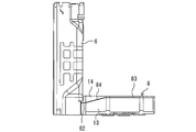
- FIG. 5 is a rear view showing a state where the heat insulating member is fitted to the partition plate.
- the heat insulating member 8 is mainly disposed on the side surface portion 13 that covers the side surface and the bottom surface side of the water-refrigerant heat exchanger 2, and is disposed above the side surface portion 13. 2 and a cover 14 that covers the upper surface side.
- the contact portion 82 around the protruding portion 12 is configured at a position lower than the contact portion 83 of the other portion.
- the contact portion 84 between them is constituted by an inclined surface.
- the lid 14 can be slid in a direction away from the partition plate 6, the lid 14 can be removed without removing the partition plate 6. Thereby, the state of the water-refrigerant heat exchanger 2 housed in the heat insulating member 8 can be easily checked.
- FIG. 6 is a diagram showing the arrangement of the protrusions of the heat insulating member.
- the protruding portion 12 is provided at a rear portion of the contact surface 81 of the heat insulating member 8.
- the pipe 16 extending from the water-refrigerant heat exchanger 2 into the machine room 20 is routed to the rear side of the compressor 1.
- the piping of the water-refrigerant heat exchanger 2 is not in the way, so that it is possible to prevent accidental damage to the piping.
- the heat pump device according to Embodiment 1 described above may employ, for example, the following modified embodiments.
- the shape of the heat insulating member 8 is not limited to a rectangular parallelepiped as long as the heat insulating member 8 is configured as a storage container that stores the water-refrigerant heat exchanger 2 and is installed in the blower room 22.
- the first opening 11 may have another shape as long as the pipe of the water-refrigerant heat exchanger 2 passes therethrough.
- the protruding portion 12 may have another shape as long as the protruding portion 12 fits into the notch portion 10 of the partition plate 6 without any gap.
- the cutout portion 10 of the partition plate 6 is not limited to the cutout shape as long as the cutout portion 10 is configured as an opening that fits the protrusion portion 12 without a gap, and may be, for example, a hole shape.
- FIG. 7 is a view showing a modified example of the shapes of the protrusion of the heat insulating member and the cutout of the partition plate.
- FIG. 7 is a view of the protruding portion 12 and the notch portion 10 viewed from the machine room side.
- the notch 10 includes an inclined portion 101 that is inclined so that the width of the notch increases from the closing side to the opening side.
- the side surface 121 of the protruding portion 12 corresponding to the inclined portion 101 is inclined at the same inclination angle so as to fit with the inclined portion 101 without a gap.
- FIG. 8 is a view showing another modification of the shapes of the protrusion of the heat insulating member and the cutout of the partition plate.
- FIG. 8 is a view of the protruding portion 12 and the cutout portion 10 viewed from the machine room side as in FIG.
- the protrusion 12 of the heat insulating member 8 is connected to the notch 10 of the partition plate 6. It is possible to further prevent the notch 10 from being caught and damaged by the protrusion 12 of the heat insulating member 8 and the workability from deteriorating when fitted into the heat insulating member 8.
Landscapes
- Engineering & Computer Science (AREA)
- Mechanical Engineering (AREA)
- General Engineering & Computer Science (AREA)
- Chemical & Material Sciences (AREA)
- Combustion & Propulsion (AREA)
- Physics & Mathematics (AREA)
- Thermal Sciences (AREA)
- Heat-Pump Type And Storage Water Heaters (AREA)
- Other Air-Conditioning Systems (AREA)
- Housings, Intake/Discharge, And Installation Of Fluid Heaters (AREA)
Abstract
本発明に係るヒートポンプ装置(100)は、筐体と、筐体内の空間を、圧縮機(1)が収納された機械室(20)と、冷媒と空気とを熱交換させる第一熱交換器(4)、送風機(5)及び冷媒と熱媒体とを熱交換させる第二熱交換器(2)が収納された送風機室(22)とに仕切る仕切板(6)と、第二熱交換器を内部に収納した収納容器(8)と、を備える。収納容器は、第二熱交換器から延びる配管(16)を側面から外部へ連通させるための第一開口部(11)と、第一開口部の周囲に設けられ、側面から外側に向かって突出した突出部(12)と、を含んで構成される。仕切板は、配管を通すための第二開口部(10)を含んで構成される。そして、収納容器は、第二開口部を通じて送風機室の側から機械室の側へ配管を通すとともに突出部が第二開口部に嵌合するように設置される。
Description
本発明は、ヒートポンプ装置に関する。
外気から吸収した熱を用いて水などの液状熱媒体を加熱するヒートポンプシステムが広く用いられている。特許文献1には、このようなヒートポンプシステムの室外機として、圧縮機、空気冷媒熱交換器、減圧手段及び水冷媒熱交換器を順次冷媒循環配管で接続したヒートポンプサイクルを筐体内に備えた室外機が開示されている。この室外機では、仕切板によって区画した筐体内の一方に圧縮機が搭載され、もう一方の区画には送風ファンと水冷媒熱交換器が設けられている。そして、仕切板の前方下部には水冷媒熱交換器から延びる配管を圧縮機の側に通すための切欠き部が形成されている。
特許文献1の室外機では、以下の問題がある。水冷媒熱交換器は保護カバーにより覆われている。保護カバーは仕切板の切欠き部に係合される。しかしながら、この保護カバーは、切欠き部を完全に塞いでいない。このため、送風ファンの側の虫または小動物などに代表される異物が切欠き部の隙間から圧縮機の側に侵入するおそれがある。これらの異物は、圧縮機の側に配置されている電子部品の故障の原因となる。
本発明は、上述のような課題を解決するためになされたもので、送風機が配置された送風機室側と圧縮機が配置された機械室側とを仕切板によって区画したヒートポンプ装置において、配管を通すための仕切板の開口を通じて送風機室側から機械室側へと異物が侵入することを抑制することのできるヒートポンプ装置を提供することを目的とする。
本発明に係るヒートポンプ装置は、冷媒を圧縮する圧縮機と、冷媒と空気とを熱交換させる第一熱交換器と、送風機と、冷媒と熱媒体とを熱交換させる第二熱交換器と、を内部に収納する筐体と、筐体内の空間を、圧縮機が収納された機械室と、第一熱交換器、送風機及び第二熱交換器が収納された送風機室とに仕切る仕切板と、第二熱交換器を内部に収納した収納容器と、を備える。収納容器は、第二熱交換器から延びる配管を側面から外部へ連通させるための第一開口部と、第一開口部の周囲に設けられ、側面から外側に向かって突出した突出部と、を含んで構成される。仕切板は、配管を通すための第二開口部を含んで構成される。そして、収納容器は、第二開口部を通じて送風機室の側から機械室の側へ配管を通すとともに突出部が第二開口部に嵌合するように設置される。
本発明のヒートポンプ装置によれば、仕切板に開口した第二開口部が収納容器の突出部に嵌合している。これにより、送風機室側から機械室側へと第二開口部を介して異物が侵入することを抑制することが可能となる。
以下、図面を参照して実施の形態について説明する。各図において共通する要素には、同一の符号を付して、重複する説明を簡略化または省略する。また、本開示は、以下の各実施の形態で説明する構成のうち、組み合わせ可能な構成のあらゆる組み合わせを含み得る。
実施の形態1.
図1は、実施の形態1のヒートポンプ装置の内部構造を示す正面図である。図2は、実施の形態1のヒートポンプ装置の内部構造を斜め前から見た斜視図である。本実施の形態のヒートポンプ装置100は、室外に設置される。ヒートポンプ装置100は、液状の熱媒体を加熱する。本実施の形態での熱媒体は、水である。ヒートポンプ装置100は、水を加熱して湯を生成する。本発明における熱媒体は、例えば塩化カルシウム水溶液、エチレングリコール水溶液、アルコールなどでもよい。
図1は、実施の形態1のヒートポンプ装置の内部構造を示す正面図である。図2は、実施の形態1のヒートポンプ装置の内部構造を斜め前から見た斜視図である。本実施の形態のヒートポンプ装置100は、室外に設置される。ヒートポンプ装置100は、液状の熱媒体を加熱する。本実施の形態での熱媒体は、水である。ヒートポンプ装置100は、水を加熱して湯を生成する。本発明における熱媒体は、例えば塩化カルシウム水溶液、エチレングリコール水溶液、アルコールなどでもよい。
図1に示すように、ヒートポンプ装置100は、筐体の底部を形成する底板7を備える。底板7上には、前方から見て、右側に機械室20が形成され、左側に送風機室22が形成されている。機械室20と送風機室22とは、鉛直方向に延在する仕切板6により隔てられている。ヒートポンプ装置100の外郭を形成する筐体は、上述した底板7の他、図示しないフロントパネルと、バックパネルと、トップパネルと、を更に備える。フロントパネルは、筐体の前面を覆う前面部と筐体の左側面を覆う左側面部とから構成されている。また、バックパネルは、筐体の後面を覆う後面部と筐体の右側面を覆う右側面部とから構成されている。トップパネルは、筐体の上面部を覆うように構成されている。筐体のこれらの構成要素は例えば板金材から成形される。ヒートポンプ装置100の外面は、後面側に配置された空気冷媒熱交換器4を除いて、この筐体によって覆われている。前面部には、送風機室22を通った空気を排出するための開口が形成され、この開口には格子が取り付けられている。なお、図1及び図2は、底板7以外の筐体の各部を取り外した状態を示している。また、図1では、一部の構成機器の図示を省略している。
図1に示すように、機械室20内には、冷媒回路部品として、冷媒を圧縮する圧縮機1、冷媒を減圧する膨張弁3、これらを接続する吸入管及び吐出管等の冷媒管などが組み込まれている。
圧縮機1は、円筒形のシェルの内部にある圧縮部(図示省略)及びモータ(図示省略)を備える。圧縮部は、冷媒の圧縮動作を行う。モータは、圧縮部を駆動する。外部から供給される電力により圧縮機1のモータが駆動される。吸入管を通って冷媒が圧縮機1に吸入される。圧縮機1の内部で圧縮された冷媒を吐出する吐出管が圧縮機1の上部に接続されている。膨張弁3は、その本体の外側面にコイル組み込み部材が取り付けられている。コイルに外部から通電することにより、内部の流路抵抗調節部を稼動させて冷媒の流路抵抗を調節する。膨張弁3により、その上流側の高圧冷媒の圧力と、その下流側の低圧冷媒の圧力とを調節できる。膨張弁3は、冷媒を減圧する減圧装置の例である。
送風機室22は、風路を確保するため、機械室20より大きな空間を有する。送風機室22内には、送風機5が組み込まれている。送風機5は、複数枚のプロペラ翼とプロペラ翼を回転駆動させるモータとを備える。外部から供給される電力によりモータ及びプロペラ翼が回転する。送風機室22の後面側には、送風機5に対向して、第一熱交換器としての空気冷媒熱交換器4が設置されている。空気冷媒熱交換器4は、多数のアルミ薄板のフィンと、アルミ薄板のフィンに多数密着して数回往復する長い冷媒管とを備える。それぞれのフィンは、縦長の矩形形状を有し、横方向に微小隙間を隔てながら積層された状態で冷媒管に固定されている。空気冷媒熱交換器4は、L字状に曲がった平板状の外形を有する。空気冷媒熱交換器4は、ヒートポンプ装置100の後面から左側面にかけて設置されている。空気冷媒熱交換器4の後面側の端部は、機械室20の後側まで延びている。このため、仕切板6は、L字状に曲がった平板状の外形を有し、ヒートポンプ装置100の前面から空気冷媒熱交換器4の後面側の端部までの空間を仕切るように設置される。空気冷媒熱交換器4では、冷媒管内の冷媒とフィン周辺の空気との間で熱を交換する。送風機5により各フィン間を流れて通過する空気の風量が増やされて調節され、熱交換の量が増やされて調節されている。空気冷媒熱交換器4は、冷媒を蒸発させる蒸発器の例である。
送風機室22の下部の底板7の上に、第二熱交換器としての水冷媒熱交換器2が設置されている。水冷媒熱交換器2は、断熱部材8及び保護カバー9に覆われた状態で底板7に設置されている。水冷媒熱交換器2は、長い水管と長い冷媒管とが密着した状態で、断熱部材8に収納可能となるように曲げ成形されている。水冷媒熱交換器2内では、冷媒管内の冷媒と、水管内の水すなわち熱媒体との間で熱を交換する。水冷媒熱交換器2内では、水すなわち熱媒体が加熱される。水冷媒熱交換器2の上方に送風機5が配置されている。
圧縮機1の出口部は、吐出管を介して、水冷媒熱交換器2の冷媒入口部に接続されている。水冷媒熱交換器2の冷媒出口部は、冷媒管を介して、機械室20内の膨張弁3の入口部に接続されている。膨張弁3の出口部は、冷媒管を介して、空気冷媒熱交換器4の冷媒入口部に接続されている。空気冷媒熱交換器4の冷媒出口部は、吸入管を介して、圧縮機1の入口部に接続されている。各冷媒管の途中には、その他の冷媒回路部品が取り付けられていてもよい。
ヒートポンプ装置100が備える冷媒回路の密閉空間内には、冷媒が封入されている。冷媒は、例えば、CO2冷媒でもよい。
次に、実施の形態1のヒートポンプ装置100の特徴的構成について説明する。実施の形態1のヒートポンプ装置100は、断熱部材8を仕切板6に嵌合させる構成に特徴を有している。図3は、断熱部材及び仕切板の構成を示す斜視図である。また、図4は、断熱部材を仕切板に嵌合させた状態を示す斜視図である。
図3及び図4に示すように、断熱部材8は直方体形状を有している。断熱部材8の側面のうち仕切板6に接触する接触面81には、水冷媒熱交換器2から延びる水管及び冷媒管を外部へ連通させるための矩形の第一開口部11が設けられている。また、第一開口部11の周囲には、仕切板6に向かって矩形形状に突出した突出部12が設けられている。
水冷媒熱交換器2が送風機室22の側に配置されている構成では、水冷媒熱交換器2から延びる配管を機械室20の側へと通す必要がある。そこで、仕切板6には、第二開口部としての切欠き部10が設けられている。切欠き部10は、仕切板6における断熱部材8と対向する面の下端側から上方に向かって切り欠いた矩形形状の切欠きである。切欠き部10は、断熱部材8を底板7に固定した状態において、断熱部材の突出部12が当該切欠き部10に隙間なく嵌合するように、その位置及び形状が定められている。
送風機室22は外部空間から空気を取り込む構造のため、外部空気とともに虫又は小動物等が侵入することがある。このような異物が仕切板6の隙間から機械室20の側に侵入すると、機械室20に設置されている電子部品の故障を引き起こすおそれがある。
実施の形態1のヒートポンプ装置100では、仕切板6の切欠き部10が断熱部材8の突出部12に隙間なく嵌合している。このような構成によれば、仕切板6に隙間を生じさせることなく送風機室22から機械室20の側へと配管を通すことができる。これにより、機械室20への異物の侵入を抑制することができるので、ヒートポンプ装置100の信頼性を高めることが可能となる。
また、断熱部材8は、その形状にも特徴を有している。図5は、断熱部材を仕切板に嵌合させた状態を示す背面図である。この図に示すように、断熱部材8は、主に水冷媒熱交換器2の側面側及び底面側を覆う側面部13と、当該側面部13の上側に配置され、主に水冷媒熱交換器2の上面側を覆う蓋部14とを含んで構成されている。そして、図5に示す例では、側面部13と蓋部14との接触部のうち、突出部12の周囲の接触部82が他の部分の接触部83よりも低い位置に構成され、これらの間の接触部84が、傾斜面によって構成されている。このような構成によれば、蓋部14を仕切板6から離れる方向にスライドさせることができるので、仕切板6を外すことなく蓋部14を取り外すことが可能となる。これにより、断熱部材8内に収納されている水冷媒熱交換器2の状態を容易に確認することが可能となる。
また、断熱部材8は、突出部12の配置にも特徴を有している。図6は、断熱部材の突出部の配置を示す図である。この図に示すように、突出部12は、断熱部材8の接触面81における後方部に設けられている。このような配置によれば、水冷媒熱交換器2から機械室20内へと延びる配管16が圧縮機1の後方側に取り回される。これにより、圧縮機1のサービスメンテナンスを行う際に水冷媒熱交換器2の配管が邪魔にならないため、誤って配管を損傷してしまうことを防ぐことができる。
上述した実施の形態1のヒートポンプ装置は、例えば以下のように変形した態様を採用してもよい。
断熱部材8は、内部に水冷媒熱交換器2を収納して送風機室22に設置される収納容器として構成されていれば、その形状は直方体形状に限らない。第一開口部11についても、水冷媒熱交換器2の配管が通る形状であれば、他の形状を採用してもよい。また、突出部12は、仕切板6の切欠き部10に隙間なく嵌合する形状であれば、他の形状を採用してもよい。更に、仕切板6の切欠き部10は、突出部12と隙間なく嵌合する開口部として構成されていれば切欠き形状に限らず、例えば穴形状でもよい。
図7は、断熱部材の突出部及び仕切板の切欠き部の形状の変形例を示す図である。なお、図7は、機械室の側から突出部12及び切欠き部10を見た図である。この図に示す変形例では、切欠き部10は、閉口側から開口側へ向かうにつれて切欠き幅が拡がるように傾斜した傾斜部101を含んで構成されている。そして、傾斜部101に対応する突出部12の側面121は、傾斜部101との間で隙間なく嵌合するように、同様の傾斜角で傾斜している。このような構成によれば、断熱部材8の突出部12を仕切板6の切欠き部10に嵌合させる際に、当該切欠き部10が断熱部材8の突出部12に引っ掛かり破損すること及び組み立て作業性が悪化することを防ぐことが可能となる。
図8は、断熱部材の突出部及び仕切板の切欠き部の形状の他の変形例を示す図である。なお、図8は、図7と同様に機械室の側から突出部12及び切欠き部10を見た図である。この図に示す変形例では、切欠き部10の開口側の端部に角R102が設けられているこのような構成によれば、断熱部材8の突出部12を仕切板6の切欠き部10に嵌合させる際に、当該切欠き部10が断熱部材8の突出部12に引っかかり破損すること及び作業性が悪化することを更に防ぐことが可能となる。
1 圧縮機、 2 水冷媒熱交換器、 3 膨張弁、 4 空気冷媒熱交換器、 5 送風機、 6 仕切板、 7 底板、 8 断熱部材、 9 保護カバー、 10 切欠き部、 11 第一開口部、 12 突出部、 13 側面部、 14 蓋部、 20 機械室、 22 送風機室、 81 接触面、 82,83,84 接触部、 100 ヒートポンプ装置、 101 傾斜部、 121 側面、 102 角R
Claims (5)
- 冷媒を圧縮する圧縮機と、冷媒と空気とを熱交換させる第一熱交換器と、送風機と、冷媒と熱媒体とを熱交換させる第二熱交換器と、を内部に収納する筐体と、
前記筐体内の空間を、前記圧縮機が収納された機械室と、前記第一熱交換器、前記送風機及び前記第二熱交換器が収納された送風機室とに仕切る仕切板と、
前記第二熱交換器を内部に収納した収納容器と、を備え、
前記収納容器は、
前記第二熱交換器から延びる配管を側面から外部へ連通させるための第一開口部と、
前記第一開口部の周囲に設けられ、前記側面から外側に向かって突出した突出部と、を含んで構成され、
前記仕切板は、前記配管を通すための第二開口部を含んで構成され、
前記収納容器は、前記第二開口部を通じて前記送風機室の側から前記機械室の側へ前記配管を通すとともに前記突出部が前記第二開口部に嵌合するように設置されることを特徴とするヒートポンプ装置。 - 前記収納容器は、
前記第二熱交換器の側面側及び底面側を覆う側面部と、
前記側面部の上側に配置され、前記第二熱交換器の上面側を覆う蓋部と、を含み、
前記蓋部は、前記仕切板から離れる方向にスライドさせて取り外し可能に構成されていることを特徴とする請求項1に記載のヒートポンプ装置。 - 前記第二開口部は、前記仕切板の下端側から上方に向かって矩形に切り欠いた切欠き部として構成され、
前記切欠き部は、閉口側から開口側に向かうにつれて切欠き幅が拡がるように傾斜した傾斜部を含んで構成され、
前記突出部を構成する側面のうち前記傾斜部に対応する側面は、前記傾斜部と同じ傾斜角で傾斜するように構成されていることを特徴とする請求項1又は請求項2に記載のヒートポンプ装置。 - 前記第二開口部は、前記切欠き部の開口側の端部に角Rが形成されていることを特徴とする請求項3に記載のヒートポンプ装置。
- 前記突出部は、前記側面における後方部に設けられ、
前記配管は、前記機械室において前記圧縮機の後方側に取り回されるように構成されることを特徴とする請求項1から請求項4の何れか1項に記載のヒートポンプ装置。
Priority Applications (3)
| Application Number | Priority Date | Filing Date | Title |
|---|---|---|---|
| EP18923910.6A EP3816535A4 (en) | 2018-06-29 | 2018-06-29 | Heat pump device |
| JP2020527142A JP6940000B2 (ja) | 2018-06-29 | 2018-06-29 | ヒートポンプ装置 |
| PCT/JP2018/024895 WO2020003511A1 (ja) | 2018-06-29 | 2018-06-29 | ヒートポンプ装置 |
Applications Claiming Priority (1)
| Application Number | Priority Date | Filing Date | Title |
|---|---|---|---|
| PCT/JP2018/024895 WO2020003511A1 (ja) | 2018-06-29 | 2018-06-29 | ヒートポンプ装置 |
Publications (1)
| Publication Number | Publication Date |
|---|---|
| WO2020003511A1 true WO2020003511A1 (ja) | 2020-01-02 |
Family
ID=68984782
Family Applications (1)
| Application Number | Title | Priority Date | Filing Date |
|---|---|---|---|
| PCT/JP2018/024895 Ceased WO2020003511A1 (ja) | 2018-06-29 | 2018-06-29 | ヒートポンプ装置 |
Country Status (3)
| Country | Link |
|---|---|
| EP (1) | EP3816535A4 (ja) |
| JP (1) | JP6940000B2 (ja) |
| WO (1) | WO2020003511A1 (ja) |
Citations (5)
| Publication number | Priority date | Publication date | Assignee | Title |
|---|---|---|---|---|
| JP2011196560A (ja) | 2010-03-17 | 2011-10-06 | Panasonic Corp | ヒートポンプ給湯機 |
| JP2012145274A (ja) * | 2011-01-12 | 2012-08-02 | Mitsubishi Electric Corp | ヒートポンプ給湯室外機 |
| JP2012247186A (ja) * | 2012-09-14 | 2012-12-13 | Panasonic Corp | ヒートポンプ給湯機 |
| JP2013047591A (ja) * | 2011-08-29 | 2013-03-07 | Noritz Corp | ヒートポンプ給湯装置 |
| JP2016191535A (ja) * | 2015-03-31 | 2016-11-10 | ダイキン工業株式会社 | 室外機 |
Family Cites Families (2)
| Publication number | Priority date | Publication date | Assignee | Title |
|---|---|---|---|---|
| JP5333287B2 (ja) * | 2010-02-24 | 2013-11-06 | 株式会社富士通ゼネラル | 空気調和機の室外機 |
| JP6489211B2 (ja) * | 2015-05-11 | 2019-03-27 | 三菱電機株式会社 | ヒートポンプ装置 |
-
2018
- 2018-06-29 EP EP18923910.6A patent/EP3816535A4/en not_active Withdrawn
- 2018-06-29 JP JP2020527142A patent/JP6940000B2/ja not_active Expired - Fee Related
- 2018-06-29 WO PCT/JP2018/024895 patent/WO2020003511A1/ja not_active Ceased
Patent Citations (5)
| Publication number | Priority date | Publication date | Assignee | Title |
|---|---|---|---|---|
| JP2011196560A (ja) | 2010-03-17 | 2011-10-06 | Panasonic Corp | ヒートポンプ給湯機 |
| JP2012145274A (ja) * | 2011-01-12 | 2012-08-02 | Mitsubishi Electric Corp | ヒートポンプ給湯室外機 |
| JP2013047591A (ja) * | 2011-08-29 | 2013-03-07 | Noritz Corp | ヒートポンプ給湯装置 |
| JP2012247186A (ja) * | 2012-09-14 | 2012-12-13 | Panasonic Corp | ヒートポンプ給湯機 |
| JP2016191535A (ja) * | 2015-03-31 | 2016-11-10 | ダイキン工業株式会社 | 室外機 |
Non-Patent Citations (1)
| Title |
|---|
| See also references of EP3816535A4 * |
Also Published As
| Publication number | Publication date |
|---|---|
| JP6940000B2 (ja) | 2021-09-22 |
| EP3816535A1 (en) | 2021-05-05 |
| EP3816535A4 (en) | 2021-06-23 |
| JPWO2020003511A1 (ja) | 2021-06-24 |
Similar Documents
| Publication | Publication Date | Title |
|---|---|---|
| JP6501908B2 (ja) | 室外機 | |
| JP3821153B2 (ja) | 空気調和装置の室外ユニット | |
| CN107076433B (zh) | 室外机 | |
| JP6593402B2 (ja) | 冷凍装置の室外ユニット | |
| JP6747614B2 (ja) | ヒートポンプ給湯室外機 | |
| JP6921326B2 (ja) | ヒートポンプ給湯室外機 | |
| JP2007120900A (ja) | 閉鎖弁サポート部材及びそれを備えた空気調和装置の室外ユニット | |
| JP6489211B2 (ja) | ヒートポンプ装置 | |
| WO2018167928A1 (ja) | ヒートポンプ装置 | |
| JP2016121864A (ja) | 空気調和機の室外機 | |
| JP2010054168A (ja) | 空気調和機の室外機 | |
| EP3734194A1 (en) | Heat pump hot water supplying outdoor unit | |
| JP6938396B2 (ja) | ヒートポンプ室外機 | |
| WO2020003511A1 (ja) | ヒートポンプ装置 | |
| JP5880123B2 (ja) | ヒートポンプ室外機 | |
| JP2014031902A (ja) | ヒートポンプ給湯室外機 | |
| JP2011142131A (ja) | 冷凍装置 | |
| JP5423509B2 (ja) | ヒートポンプ給湯機 | |
| JP6137114B2 (ja) | 空気調和装置の熱源ユニット | |
| JP2006214633A (ja) | 空気調和装置の室外ユニット | |
| JP2006214632A (ja) | 空気調和装置の室外ユニット | |
| JP6635202B2 (ja) | ヒートポンプ装置 | |
| JP7344130B2 (ja) | ヒートポンプ式温水暖房装置 | |
| JP7257799B2 (ja) | 貯湯式給湯装置 | |
| JP6743968B2 (ja) | 水冷媒熱交換器及び水熱交換器を備えたヒートポンプ装置 |
Legal Events
| Date | Code | Title | Description |
|---|---|---|---|
| 121 | Ep: the epo has been informed by wipo that ep was designated in this application |
Ref document number: 18923910 Country of ref document: EP Kind code of ref document: A1 |
|
| ENP | Entry into the national phase |
Ref document number: 2020527142 Country of ref document: JP Kind code of ref document: A |
|
| NENP | Non-entry into the national phase |
Ref country code: DE |
|
| WWE | Wipo information: entry into national phase |
Ref document number: 2018923910 Country of ref document: EP |