WO2020003521A1 - Dispositif à fluide, système et procédé de mélange - Google Patents
Dispositif à fluide, système et procédé de mélange Download PDFInfo
- Publication number
- WO2020003521A1 WO2020003521A1 PCT/JP2018/024911 JP2018024911W WO2020003521A1 WO 2020003521 A1 WO2020003521 A1 WO 2020003521A1 JP 2018024911 W JP2018024911 W JP 2018024911W WO 2020003521 A1 WO2020003521 A1 WO 2020003521A1
- Authority
- WO
- WIPO (PCT)
- Prior art keywords
- flow path
- valve
- substrate
- solution
- flow
- Prior art date
- Legal status (The legal status is an assumption and is not a legal conclusion. Google has not performed a legal analysis and makes no representation as to the accuracy of the status listed.)
- Ceased
Links
Images



Classifications
-
- G—PHYSICS
- G01—MEASURING; TESTING
- G01N—INVESTIGATING OR ANALYSING MATERIALS BY DETERMINING THEIR CHEMICAL OR PHYSICAL PROPERTIES
- G01N1/00—Sampling; Preparing specimens for investigation
- G01N1/28—Preparing specimens for investigation including physical details of (bio-)chemical methods covered elsewhere, e.g. G01N33/50, C12Q
- G01N1/38—Diluting, dispersing or mixing samples
-
- B—PERFORMING OPERATIONS; TRANSPORTING
- B01—PHYSICAL OR CHEMICAL PROCESSES OR APPARATUS IN GENERAL
- B01L—CHEMICAL OR PHYSICAL LABORATORY APPARATUS FOR GENERAL USE
- B01L3/00—Containers or dishes for laboratory use, e.g. laboratory glassware; Droppers
- B01L3/50—Containers for the purpose of retaining a material to be analysed, e.g. test tubes
- B01L3/502—Containers for the purpose of retaining a material to be analysed, e.g. test tubes with fluid transport, e.g. in multi-compartment structures
- B01L3/5027—Containers for the purpose of retaining a material to be analysed, e.g. test tubes with fluid transport, e.g. in multi-compartment structures by integrated microfluidic structures, i.e. dimensions of channels and chambers are such that surface tension forces are important, e.g. lab-on-a-chip
- B01L3/502738—Containers for the purpose of retaining a material to be analysed, e.g. test tubes with fluid transport, e.g. in multi-compartment structures by integrated microfluidic structures, i.e. dimensions of channels and chambers are such that surface tension forces are important, e.g. lab-on-a-chip characterised by integrated valves
-
- G—PHYSICS
- G01—MEASURING; TESTING
- G01N—INVESTIGATING OR ANALYSING MATERIALS BY DETERMINING THEIR CHEMICAL OR PHYSICAL PROPERTIES
- G01N35/00—Automatic analysis not limited to methods or materials provided for in any single one of groups G01N1/00 - G01N33/00; Handling materials therefor
- G01N35/08—Automatic analysis not limited to methods or materials provided for in any single one of groups G01N1/00 - G01N33/00; Handling materials therefor using a stream of discrete samples flowing along a tube system, e.g. flow injection analysis
-
- G—PHYSICS
- G01—MEASURING; TESTING
- G01N—INVESTIGATING OR ANALYSING MATERIALS BY DETERMINING THEIR CHEMICAL OR PHYSICAL PROPERTIES
- G01N37/00—Details not covered by any other group of this subclass
-
- B—PERFORMING OPERATIONS; TRANSPORTING
- B01—PHYSICAL OR CHEMICAL PROCESSES OR APPARATUS IN GENERAL
- B01L—CHEMICAL OR PHYSICAL LABORATORY APPARATUS FOR GENERAL USE
- B01L2300/00—Additional constructional details
- B01L2300/08—Geometry, shape and general structure
- B01L2300/0861—Configuration of multiple channels and/or chambers in a single devices
- B01L2300/0874—Three dimensional network
-
- B—PERFORMING OPERATIONS; TRANSPORTING
- B01—PHYSICAL OR CHEMICAL PROCESSES OR APPARATUS IN GENERAL
- B01L—CHEMICAL OR PHYSICAL LABORATORY APPARATUS FOR GENERAL USE
- B01L2300/00—Additional constructional details
- B01L2300/08—Geometry, shape and general structure
- B01L2300/0887—Laminated structure
-
- B—PERFORMING OPERATIONS; TRANSPORTING
- B01—PHYSICAL OR CHEMICAL PROCESSES OR APPARATUS IN GENERAL
- B01L—CHEMICAL OR PHYSICAL LABORATORY APPARATUS FOR GENERAL USE
- B01L2300/00—Additional constructional details
- B01L2300/12—Specific details about materials
- B01L2300/123—Flexible; Elastomeric
-
- B—PERFORMING OPERATIONS; TRANSPORTING
- B01—PHYSICAL OR CHEMICAL PROCESSES OR APPARATUS IN GENERAL
- B01L—CHEMICAL OR PHYSICAL LABORATORY APPARATUS FOR GENERAL USE
- B01L2400/00—Moving or stopping fluids
- B01L2400/04—Moving fluids with specific forces or mechanical means
- B01L2400/0475—Moving fluids with specific forces or mechanical means specific mechanical means and fluid pressure
- B01L2400/0487—Moving fluids with specific forces or mechanical means specific mechanical means and fluid pressure fluid pressure, pneumatics
-
- B—PERFORMING OPERATIONS; TRANSPORTING
- B01—PHYSICAL OR CHEMICAL PROCESSES OR APPARATUS IN GENERAL
- B01L—CHEMICAL OR PHYSICAL LABORATORY APPARATUS FOR GENERAL USE
- B01L2400/00—Moving or stopping fluids
- B01L2400/06—Valves, specific forms thereof
- B01L2400/0633—Valves, specific forms thereof with moving parts
- B01L2400/0655—Valves, specific forms thereof with moving parts pinch valves
-
- G—PHYSICS
- G01—MEASURING; TESTING
- G01N—INVESTIGATING OR ANALYSING MATERIALS BY DETERMINING THEIR CHEMICAL OR PHYSICAL PROPERTIES
- G01N1/00—Sampling; Preparing specimens for investigation
- G01N1/28—Preparing specimens for investigation including physical details of (bio-)chemical methods covered elsewhere, e.g. G01N33/50, C12Q
- G01N1/38—Diluting, dispersing or mixing samples
- G01N2001/386—Other diluting or mixing processes
Definitions
- the present invention relates to a fluid device and a system and a mixing method.
- ⁇ -TAS Micro-Total Analysis Systems
- ⁇ -TAS is superior to conventional testing devices in that it can be measured and analyzed with a small amount of sample, can be carried around, and can be disposable at low cost. Furthermore, it is attracting attention as a highly useful method when an expensive reagent is used or a small amount of a large number of samples are tested.
- Non-Patent Document 1 a device including a flow path and a pump disposed on the flow path has been reported.
- a plurality of solutions are injected into the flow path and the pump is operated to mix the plurality of solutions in the flow path.
- the first substrate, the second substrate, and the third substrate sequentially stacked in a thickness direction, and the first substrate, the second substrate, and the third substrate are provided on one of the first substrate and the second substrate.
- a first flow path formed by a groove along a first direction parallel to a bonding surface between the first substrate and the second substrate by being covered by the other of the one substrate and the second substrate;
- the second substrate which is provided on one of the second substrate and is covered by the other of the first substrate and the second substrate, includes the shared portion, and is parallel to the bonding surface and intersects the first direction.
- a first portion formed of a groove along the first substrate and one of the second substrate and the third substrate;
- a second portion formed by a groove along the second direction by being covered by the other of the plate and the third substrate; and the first portion penetrating the second substrate in the thickness direction.
- a fluid device having a second portion and a third portion connecting the second portion with each other at positions on both ends in the second direction.
- a first flow path including a stacked first substrate and a second substrate, and a groove provided in at least one of the first substrate and the second substrate.
- a plurality of passages, a plurality of parts provided independently of each other along a direction in which the fluid flows in the first flow passage, and a shared portion sharing a part of the flow passage with the first flow passage;
- An annular second flow path configured by a non-shared part that does not share a part, wherein the shared part of the plurality of second flow paths is adjacent to each other and connected via a valve in the first flow path.
- a fluid device is provided.
- a fluid device according to the first or second aspect of the present invention, and a valve for adjusting a flow of a fluid in the flow path when set in the fluid device And a supply unit capable of independently supplying a force for deforming the valve to each of the valves.
- a fluid device according to the first aspect of the present invention, and a force for collectively deforming the drive valves arranged linearly over the plurality of second flow paths.
- a second supply unit that can be supplied via a supply path arranged along the straight line.
- a first substrate and a second substrate sequentially laminated in a thickness direction, and a groove provided on at least one of the first substrate and the second substrate A first flow path, and a plurality of annular second flow paths independently provided along a direction in which fluid flows in the first flow path.
- a shared portion that is configured by a groove provided on at least one of the first substrate and the second substrate, and shares a part of the flow path with the first flow path;
- Providing a fluid device having a non-shared portion that does not share a part of a channel introducing a first solution into the first channel, and providing a non-shared portion in the plurality of second channels.
- Introducing a second solution respectively, and changing the shared portion from a part of the first flow path to a part of the second flow path And be replaced Ri, in the second flow path, the method comprising mixing the first solution and the second solution, mixing method comprising is provided.
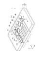
- FIG. 1 is an external perspective view schematically illustrating a fluid device according to an embodiment.
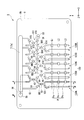
- FIG. 1 is a plan view schematically showing a fluid device according to an embodiment.
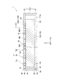
- FIG. 3 is a sectional view taken along line AA in FIG. 2.
- FIG. 3 is a sectional view taken along line BB in FIG. 2.
- FIG. 6 is a cross-sectional view of the base material 5 taken along line CC in FIG. 5.
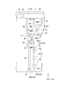
- FIG. 1 is a partial plan view schematically illustrating a fluid device according to an embodiment.
- FIG. 1 is an external perspective view schematically illustrating a fluid device according to an embodiment.
- FIG. 1 is a cross-sectional view illustrating a basic configuration of a system SYS according to an embodiment.
- FIG. 2 is a plan view showing a driving unit TR of the system SYS according to the embodiment.
- FIG. 9 is a partial plan view showing a modified example of the first channel 110 and the second channels 120
- FIG. 1 is an external perspective view schematically showing a fluid device 1 of the present embodiment.
- FIG. 2 is a plan view schematically illustrating an example of a flow channel provided in the fluid device 1.
- the transparent upper plate 6 is illustrated in a state where the components disposed on the lower side are transmitted.
- FIG. 3 is a sectional view taken along line AA in FIG.
- FIG. 4 is a sectional view taken along line BB in FIG.
- the fluid device 1 of the present embodiment includes, as an example, a device that detects a sample substance to be detected contained in a specimen sample by an immune reaction, an enzyme reaction, or the like.
- the sample substance is, for example, a biological molecule such as a nucleic acid, DNA, RNA, peptide, protein, or extracellular endoplasmic reticulum.
- the fluid device 1 includes a substrate 5.
- the substrate 5 has three substrates (a first substrate 6, a second substrate 9, and a third substrate 8) stacked in the thickness direction.
- the first substrate 6, the second substrate 9, and the third substrate 8 of the present embodiment are made of a resin material. Examples of the resin material constituting the first substrate 6, the second substrate 9, and the third substrate 8 include polypropylene, polycarbonate, and the like.
- the first base member 6 and the third base member 8 are made of a transparent material.
- the material which comprises the 1st base material 6, the 3rd base material 8, and the 2nd base material 9 is not limited.
- the first substrate 6, the second substrate 9, and the third substrate 8 are each arranged along a horizontal plane in a substantially rectangular plate shape as viewed from the S plane, and the first substrate 6 is located above the second substrate 9.
- the third substrate 8 will be described as being disposed below the second substrate 9. However, this merely defines the horizontal direction and the vertical direction for convenience of description, and does not limit the orientation when the fluid device 1 according to the present embodiment is used.
- the long side direction of the first substrate 6, the second substrate 9, and the third substrate 8 is defined as an X direction (first direction), and the short side direction (second direction S) is defined as a Y direction.
- the stacking direction orthogonal to the X direction and the Y direction will be appropriately described as the Z direction.
- the first substrate 6 has an upper surface 6b and a lower surface 6a.
- the second base material 9 has an upper surface 9b and a lower surface 9a.
- the third base material 8 has an upper surface 8b and a lower surface 8a.
- the lower surface 6a of the first substrate 6 faces and contacts the upper surface 9b of the second substrate 9 in the laminating direction.
- the lower surface 6a of the first substrate 6 and the upper surface 9b of the second substrate 9 are joined to each other by joining means such as adhesion.
- the lower surface 6a of the first substrate 6 and the upper surface 9b of the second substrate 9 constitute a first boundary surface (joining surface) 61. That is, the first base member 6 and the second base member 9 are joined at the first boundary surface 61.
- the upper surface 8b of the third substrate 8 faces and contacts the lower surface 9a of the second substrate 9 in the laminating direction.
- the upper surface 8b of the third substrate 8 and the lower surface 9a of the second substrate 9 are joined to each other by joining means such as adhesion.
- the upper surface 8b of the third base member 8 and the lower surface 9a of the second base member 9 form a second boundary surface (joining surface) 62. That is, the second base material 9 and the third base material 8 are joined at the second boundary surface 62.
- the base material 5 includes a flow path 11, a reservoir 29, an injection hole 32, a waste liquid tank 7, a discharge path 37, an air hole 35, a supply path 39, Valves V1 to V16, V21 to V22, and a pump P are provided.
- the waste liquid tank 7 is provided on the base material 5 to discard the solution in the flow path 11.
- the waste liquid tank 7 is formed in a space on the inner wall surface of the through hole 7 a penetrating the second substrate 9, the lower surface 6 a of the first substrate 6, and the upper surface 8 b of the third substrate 8. As shown in FIGS. 1 and 2, the waste liquid tank 7 is formed to extend in the X direction.
- the waste liquid tank 7 is arranged near the + Y side edge of the second substrate 9.
- the air holes 35 are provided through the first substrate 6 and the second substrate 9. As shown in FIGS. 1 and 2, the air holes 35 are arranged at intervals on the ⁇ X side of the waste liquid tank 7. On the lower surface 9a of the second substrate 9, there is formed a groove 36 for communicating the waste liquid tank 7 with the air hole 35.
- the flow path 11 includes a first flow path 110 formed of a groove along the X direction, and a plurality of flow paths 11 provided independently of each other along the X direction (FIGS. 1 and 2).
- first flow path 110 formed of a groove along the X direction
- second flow paths 120A to 120E there are five second flow paths 120A to 120E (hereinafter, appropriately referred to as second flow paths 120).
- the groove portion extends along the X direction means that a straight line connecting both ends in the length of the groove portion is substantially parallel to the X direction.
- the first flow path 110 is provided on the upper surface 9 b of the second substrate 9 and is formed by being covered by the first substrate 6.
- the first flow path 110 has a plurality of quantitative sections GB1 to GB5 arranged in the X direction corresponding to the plurality of second flow paths 120A to 120E, an introduction path 51, and a discharge path 52.
- the quantification units GB1 to GB5 have the same shape, size, and volume.
- the shapes and sizes of the quantification units GB1 to GB5 are the same (common), it is possible to share the valve arrangement in the plurality of second flow paths 120A to 120E.
- the shapes, sizes, and volumes of the quantification units GB1 to GB5 do not have to be the same.
- the volumes of the quantification units GB1 to GB5 can be easily changed without changing the arrangement of the valves. This configuration is useful, for example, when evaluating samples having different concentrations in the plurality of second flow paths 120A to 120E.
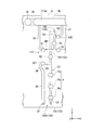
- FIG. 5 is an enlarged partial plan view of the second flow passage 120A.
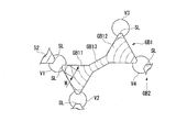
- the fixed amount part GB1 includes merging / branching parts GB11 and GB12 of a substantially equilateral triangle, and a connecting part GB13 connecting these.
- FIG. 7 is a plan view showing the details of the quantitative section GB1 as viewed in the stacking direction. As shown in FIG. 7, the merging / branching portions GB11 and GB12 are spaces each having a substantially equilateral triangular upper surface and a lower surface.
- the substantially equilateral triangle means that the longest three sides each make 60 degrees.
- the merging / branching portions GB11 and GB12 are line segments connecting vertex positions (hereinafter, simply referred to as vertex positions) of an equilateral triangle serving as a reference in a plan view (in the stacking direction (in the thickness direction of the second substrate 9)). It is formed by a dent provided on the upper surface 9b of the second substrate 9 and surrounded by a contour offset by a predetermined distance inside the equilateral triangle in parallel with.
- the merging / branching portions GB11 and GB12 in the present embodiment have upper and lower surfaces of an equilateral triangle parallel to the upper surface 9b of the second substrate 9, and side surfaces orthogonal to the upper and lower surfaces.
- the above-mentioned outline in plan view of the merging / branching portions GB11 and GB12 is formed by a ridge line where the upper surface 9b and the side surface of the second substrate 9 intersect.
- the top surface and the bottom surface forming the merging / branching portions GB11 and GB12 are equilateral triangles having the same size, and completely overlap in the stacking direction.
- a valve for adjusting the flow of the fluid in the flow channel 11 is provided (details will be described later).
- the upper surface and the bottom surface forming the merging / branching portions GB11 and GB12 are equilateral triangles whose upper surface is larger than the bottom surface. May be arranged. At this time, the side surfaces forming the merging / branching portions GB11 and GB12 are inclined inward toward the inside as going from the top surface to the bottom surface.
- the intersection position is arranged inside the equilateral triangle.
- the offset amount between the line segment and the contour is, for example, about 0.1 mm to 0.2 mm.
- the offset allows the elastomeric ground surface of the diaphragm member of the valve to be widened, so that the valve can be more stably sealed.
- the volume of the branch portion can be finely adjusted by the offset. For example, in a plurality of merging / branching portions, even if the size of the valve is common, by changing the offset amount, the branch portions having different volumes can be obtained.
- the offset amount may be such that the distance on at least one of the three sides is different from the distance on the other side.
- a difference can be made in the liquid contact area of the valve, and the internal pressure resistance of the valve having a small liquid contact area can be improved.
- One of the vertex positions in the merging / branching portion GB11 and one of the vertex positions in the merging / branching portion GB12 are arranged at the same position.
- a certain distance may be provided between one of the apex positions at the merging / branching portion GB11 and one of the apex positions at the merging / branching portion GB12.
- the first flow path 110 is configured such that the merging / branching portions of the contour of the equilateral triangle in plan view are arranged in a pair symmetrically with respect to the center point, and the connecting portion passing through the center point connects the pair of merging / branching portions.
- a plurality of standing drum-shaped (ribbon-shaped, hourglass-shaped) quantitative sections GB1 to GB5 to be connected are combined.
- the plurality of quantification units GB1 to GB5 as the common unit are arranged continuously. Adjacent fixed parts GB1 to GB5 share the apex position of the merging / branching part.
- a valve is provided at the vertex position shared by the adjacent quantitative units GB1 to GB5.
- the connecting portion GB13 is located at the same position in the merging / branching portions GB11, GB12.
- the merging / branching portions GB11 and GB12 are connected to each other via the disposed vertex positions.
- the vertex position at the merging / branching portion GB11 is determined by the connection portion GB13.
- the connection part GB13 is formed by a linear groove as an example.
- the junction / branch portions GB11, GB12 and the connection portion GB13 are formed at the same depth.
- the areas and depths (that is, volumes) of the merging / branching parts GB11, GB12 and the connection part GB13 are set according to the volume of the solution to be quantified in the quantification part GB1.
- Valves V1 and V2 are disposed at the apexes of the junction / branch GB11 where the connection GB13 is not disposed (not disposed).
- the junction / branch portion GB11 is connected to the discharge path 52 via the valve V1, and can be connected or shielded to the discharge path 52 according to opening and closing of the valve V1.
- the discharge path 52 is connected at one end to the metering section GB1 via the valve V1, and at the other end to the waste liquid tank 7.
- Valves V3 and V4 are arranged at the apexes of the junction / branch GB12 where the connection GB13 is not arranged (not arranged). As shown in FIG. 2, the merging / branching portion GB12 is connected to the fixed amount portion GB2 via the valve V4, and can be connected or shielded to the fixed amount portion GB2 according to the opening and closing of the valve V4.
- the quantitative unit GB2 is connected to the quantitative unit GB3 via the valve V7, and can be connected to or shielded from the quantitative unit GB3 according to the opening and closing of the valve V7.
- the quantitative unit GB3 is connected to the quantitative unit GB4 via the valve V10, and can be connected to or shielded from the quantitative unit GB4 according to the opening and closing of the valve V10.
- the quantitative unit GB4 is connected to the quantitative unit GB5 via the valve V13, and can be connected to or shielded from the quantitative unit GB5 according to the opening and closing of the valve V13.
- the metering unit GB5 is connected to the introduction path 51 via the valve V16, and can be connected to or blocked from the introduction path 51 according to the opening and closing of the valve V16.
- the introduction path 51 is connected at one end to the metering section GB5 via the valve V16, and at the other end to the injection hole 53.
- the injection hole 53 is formed penetrating the second substrate 9 in the thickness direction.
- the third substrate 8 has an air hole 54 at a position facing the injection hole 53 as shown in FIG.
- the air holes 54 are formed to penetrate the third substrate 8 in the thickness direction.
- the solution is injected into the injection hole 53 through the air hole 54.
- the injection hole 53 functions as a reservoir, and can store (hold) the injected solution.
- the solution to be injected and stored in the injection hole 53 includes, for example, a solution containing a sample such as a specimen.
- the first flow path 110 opens the valves V1, V4, V7, V10, V13, and V16 with the valves V2, V3, V5, V6, V8, V9, V11, V12, V14, and V15 closed. It can communicate with the injection hole 53, the waste liquid tank 7, the groove 36, and the air hole 35. In the first flow path 110, by closing the valves V1 to V16, the quantitative sections GB1 to GB5 are partitioned.
- the second flow path 120A is a circulation flow path formed in an annular shape (loop shape) along a plane substantially parallel to the YZ plane.
- the second flow path 120 ⁇ / b> A is provided on the upper surface 9 b of the second substrate 9, and is covered by the first substrate 6 and is formed by a groove along the Y direction, and the lower surface 9 a of the second substrate 9.
- a second portion 122 formed of a groove along the Y direction by being covered with the third substrate 8, and a first portion 121 and a second portion 122 penetrating the second substrate 9 in the thickness direction.
- the third portion 123 penetrates through the second substrate 9 substantially perpendicularly to, for example, the bonding surface between the first substrate 6 and the second substrate 9 and the bonding surface between the second substrate 9 and the third substrate 8. You may.
- the first portion 121 has merging / branching portions GB21, GB22, upper surface channels 131, 132, and a quantifying portion GB1.
- the quantitative section GB1 is provided as a shared section between the first flow path 110 and the second flow path 120A. That is, the quantification unit GB1, which is a shared unit, is a part of the second channel 120A, which is a circulation channel.
- the merging / branching part GB21 is, like the merging / branching parts GB11 and GB12, a contour that matches a line connecting the vertices of the equilateral triangle in plan view, or a predetermined distance parallel to the line and inside the equilateral triangle. It is formed by a depression surrounded by an offset contour.
- One of the vertex positions in the merging / branching portion GB21 and one of the vertex positions in the merging / branching portion GB11 are arranged at the same position.
- the merging / branching part GB21 and the merging / branching part GB11 can be connected or shielded according to the opening / closing of a valve V2 arranged at the same vertex position.
- the top channel 131 is connected to one of the apex positions different from the apex position where the valve V2 is arranged in the merging / branching portion GB21, and the valve V21 is arranged in the other one.
- the upper surface channel 131 extends along the Y direction.
- the upper surface channel 131 is connected to the merging / branching portion GB21 on the + Y side, and a pump P is provided in the middle.
- the pump P is composed of three element pumps (driving valves) Pe arranged side by side in the flow path.
- the element pump Pe is a so-called valve pump.
- the pump P can adjust and transport the flow of the solution in the circulation channel (the second channel 120A) by sequentially opening and closing the three element pumps Pe in cooperation with each other.
- the number of element pumps Pe constituting the pump P may be three or more, and may be, for example, 4, 5, 6, 7, 8, 9, or 10.
- each of the element pumps Pe is disposed on straight lines L1 to L3 extending in the X direction at the same position in the Y direction over the second flow paths 120A to 120E. Therefore, by supplying the utilities for driving the element pumps Pe along the straight lines L1 to L3, it becomes possible to drive the element pumps Pe of the second flow paths 120A to 120E collectively. Therefore, the flows of the solutions in the second flow paths 120A to 120E can be synchronized.
- the merging / branching part GB22 is, like the merging / branching part GB21, a contour that matches a line connecting the vertices of the equilateral triangle in plan view, or a predetermined distance parallel to the line and inside the equilateral triangle. It is formed by a depression surrounded by a contour.
- One of the vertex positions in the merging / branching portion GB22 and one of the vertex positions in the merging / branching portion GB12 are arranged at the same position.
- the merging / branching part GB22 and the merging / branching part GB12 can be connected or shielded according to the opening / closing of the valve V3 arranged at the same vertex position.
- the top surface flow path 132 is connected to one of the apex positions different from the apex position where the valve V3 is arranged in the merging / branching part GB22, and the other is provided with the valve V22.
- the upper surface channel 132 extends along the Y direction.
- the upper surface channel 132 is connected to the junction / branch portion GB22 on the ⁇ Y side.
- the second portion 122 has a lower surface channel 133.
- the lower surface channel 133 extends along the Y direction. A part of the lower flow path 133 overlaps the upper flow paths 131 and 132 and the quantitative section GB1 when viewed in the stacking direction. That is, the first portion 121 and the second portion 122 partially overlap in the thickness direction of the second substrate 9.
- the third portion 123 has connection holes 134 and 135. As shown in FIG. 3, the connection hole 134 penetrates the second substrate 9. The connection hole 134 connects the ⁇ Y side end of the upper surface channel 131 and the ⁇ Y side end of the lower surface channel 133. The connection hole 135 passes through the second substrate 9. The connection hole 135 connects the + Y side end of the upper surface channel 131 with the + Y side end of the lower surface channel 133.
- the reservoir 29 is connected to the second flow path 120A via the supply path 39, and the waste liquid tank 7 is connected to the second flow path 120A via the discharge path 37.
- the reservoir 29 is provided substantially parallel to the upper surface channel 131.
- the reservoir 29 is formed by a groove opening on the upper surface 9 b of the second substrate 9.
- An injection hole 32 penetrating in the thickness direction of the second substrate 9 and opening to the lower surface 9a is formed at the ⁇ Y side end of the reservoir 29. The solution is injected into the reservoir 29 from the lower surface 9a side through the injection hole 32 and stored.
- the reservoir 29 is provided individually and independently in each of the second flow paths 120A to 120E.
- the solution to be filled in the reservoir 29 is, for example, a reagent for the sample stored in the injection hole 53.
- the reagents filled in the second flow paths 120A to 120E reservoir 29 may be of the same type or different types.
- the supply path 39 can be connected to or shielded from the merging / branching part GB21 according to the opening / closing of the valve V21.
- the discharge path 37 can be connected to or shielded from the merging / branching part GB22 according to the opening and closing of the valve V22.
- the reservoir 29 in the second flow path 120A is partitioned from the second flow path 120A by closing the valve V21.
- FIG. 6 is a cross-sectional view of the base material 5 in FIG.
- the structure of the merging / branching portions GB11 and GB21 and the valve V2 will be described as a representative, but the other merging / branching portions and the valves V1 to V16 and V21 to V22 have the same configuration.
- the center positions of the merging / branching portions GB11 to GB12, GB21 to GB22 and the valves V1 to V16, V21 to V22 are respectively arranged at positions selected from a predetermined number of index points arranged in a two-dimensional hexagonal lattice pattern. Have been.
- the first base member 6 is provided with a valve holding hole 34 for holding the valve V2.
- the valve V2 is held by the first base member 6 in the valve holding hole 34.
- the valve V2 is made of an elastic material. Examples of the elastic material that can be used for the valve V2 include rubber and an elastomer resin.
- a hemispherical recess 40 is provided in the flow path 11 immediately below the valve V2.
- the depression 40 has a circular shape in plan view on the upper surface 9 b of the second base material 9.
- the diameter of the depression 40 in the upper surface 9b is preferably, for example, 1.0 to 3.0 mm.
- the valve V2 adjusts the flow of the solution in the flow channel 11 by elastically deforming downward to change the cross-sectional area of the flow channel.
- the valve V ⁇ b> 2 elastically deforms downward and abuts the depression 40 to close the flow path 11. Further, the valve V2 opens the flow path 11 by separating from the depression 40 (the phantom line (two-dot chain line in FIG. 6)).
- an inclined portion SL is located at the boundary between the valve V2 (dent 40) and the merging / branching portions GB11, GB21, and decreases the distance from the top surface 85p toward the valve V2.
- the inclined portion SL for example, compared with a case where the inclined portion SL is not provided and a step (corner) exists at the boundary between the bottom of the depression 40 and the bottom surface 85q of the merging / branching portions GB11 and GB21.
- the solution can be smoothly introduced into the valve V2, and the remaining bubbles at the steps (corners) can be effectively suppressed.
- the above-described inclined portion SL is provided at the boundary between each of the discharge paths 37 and 52, the supply path 39, and the introduction path 51 and the depression 40.
- the inclined portion SL is particularly effective when the flow channel 11 is flat and has lyophilicity for a solution.
- the flow path 11 being flat means that the depth of the flow path 11 is smaller than the width of the flow path 11.
- Each inclined portion SL has a tapered shape whose diameter decreases at an angle of 60 ° toward the center of the valve.
- the maximum width W (see FIG. 7) of the inclined portion SL in the tapered shape is preferably about 0.5 to 1.5 mm.
- the configuration in which the inclined portion SL is provided works effectively, but the lowest position of the depression 40 is When it is at a position lower than the bottom surface 85q of the merging / branching portions GB11 and GB21, the bottom surface 85q and the recess 40 may intersect without providing the inclined portion SL.
- the valves V2, V3, V5, V6, V8, V9, V11, V12, V14, V15 are closed, and the valves V1, V4, V7, V10, V13 , V16 are released.
- the quantification units GB1 to GB5, the introduction path 51, and the discharge path 52 that constitute the first flow path 110 communicate with the injection hole 53, the waste liquid tank 7, the groove 36, and the air hole 35.
- the inside of the waste liquid tank 7 is suctioned at a negative pressure from the air holes 35 shown in FIGS. 1 and 2 and FIGS.
- the solution in the injection hole 53 moves to the flow channel 11 via the introduction channel 51.
- the air that has passed through the air holes 54 is introduced behind the solution in the introduction path 51.
- the solution accommodated in the injection hole 53 is sequentially introduced into the quantification units GB5 to GB1 and the discharge path 52 via the introduction path 51.
- valve (third valve) V2 and the valve (fourth valve) V3 are closed, the valve (first valve) V1 and the valve (first valve) V4 are opened, and when the solution is introduced into the quantitative portion GB1,
- the solution introduced from the portion GB2 to the merge / branch portion GB12 via the valve V4 is introduced to the merge / branch portion GB11 via the connection portion GB13.
- the solution is supplied to the boundary between the fixed amount portion GB2 and the valve V4 (the depression 40) in a state where air bubbles remain. It can be smoothly introduced and filled into the valve V4.
- the merging / branching portion GB12 is formed in an equilateral triangle in plan view, and has the same distance from the valve V4 (the depression 40) as a base point to the valve V3 and the connection portion GB13 arranged at other apexes. .
- the solution introduced from the valve V4 to the merge / branch portion GB12 reaches the valve V3 and the connection portion GB13 almost at the same time as shown by the two-dot chain line in FIG.
- the merging / branching part GB11 into which the solution is introduced via the connecting part GB13, the merging / branching part GB11 is formed in an equilateral triangle in plan view, and is located at another vertex position with the connecting part GB13 as a base point.
- the distances to the valves V1, V2 are the same. Therefore, the solution introduced from the connection part GB13 to the junction / branch part GB11 reaches the valves V1 and V2 almost at the same time as shown by the two-dot chain line in FIG. As a result, for example, it is possible to suppress a situation in which the solution that has reached the valve V1 first flows into the discharge path 52 and air bubbles remain near the valve V2.
- valves V1, V4, V7, V10, V13, and V16 are closed (that is, the valves V1 to V16 are closed), thereby partitioning the quantitative units GB1 to GB5, respectively.
- the solution SA is quantified in the quantification units GB1 to GB5 in a state where the residual air bubbles are suppressed.
- the quantification unit GB1 is separated from the first flow path 110 in a state where the solution SA is quantified.
- the valves V1 to V4 are closed and the valves V21 and V22 are opened.
- the reservoir 29 is provided with the supply path 39, the merging / branching part GB 21 and the upper surface flow path 131 constituting the first part 121, the connection hole 134 constituting the third part 123, and the lower surface flow path constituting the second part 122.
- 133, a connection hole 135 forming the third portion 123, an upper surface flow channel 132 and a merging / branching portion GB22 forming the first portion 121, and a discharge tank 37 communicate with the waste liquid tank 7.
- the inside of the waste liquid tank 7 is suctioned from the air hole 35 through the groove 36 by using the suction device described above.
- the solution in the reservoir 29 flows through the supply path 39 to the junction / branch portion GB21, the upper surface channel 131, the connection hole 134, the lower surface channel 133, the connection hole 135, the upper surface channel 132, the junction / branch portion GB22. And into the discharge path 37 sequentially.
- the merging / branching part GB21 When the solution is introduced into the merging / branching part GB21 via the supply path 39, the merging / branching part GB21 is formed in an equilateral triangle in plan view, and the valve V2 located at another vertex position with the valve V21 as a base point. And the distance to the upper surface channel 131 is the same. Therefore, the solution introduced from the supply path 39 to the merging / branching part GB21 reaches the valve V2 and the upper surface flow path 131 almost simultaneously, and is introduced into the upper surface flow path 131 in a state where bubbles remain.
- the merging / branch part GB22 is formed in an equilateral triangle in a plan view.
- the distance to the valve V3 and the discharge path 37 at the apex position is the same. Therefore, the solution introduced into the merge / branch portion GB22 reaches the valve V3 and the discharge path 37 almost at the same time, and is introduced into the discharge path 37 in a state where bubbles remain.
- the procedure for quantifying the solution SB in the second flow path 120A excluding the quantification unit GB1 may be similarly performed.
- a procedure may be adopted in which the solution is simultaneously quantified in one or more of the second flow paths 120B to 120E.
- the time required for quantifying the solution can be reduced although the negative pressure suction force of the suction device increases.
- the quantification unit GB1 becomes a part of the first flow path 110 by opening the valves V1 and V4 and closing the valves V2 and V3 among the valves V1 to V4, opening the valves V2 and V3, and opening the valves V1 and V4. Is closed so as to be a part of the second channel 120A.
- the solutions SA and SB in the second flow path 120A are sent and circulated using the pump P.
- the solutions SA and SB circulating in the second flow path 120A the flow velocity around the wall surface is low and the flow velocity in the center of the flow path is high due to the interaction (friction) between the flow path wall surface and the solution in the flow path.
- the flow rate of the solution can be distributed, mixing and reaction of the quantified solutions SA and SB are promoted.
- the quantitative sections GB1 to GB5 constituting a part of the first flow path 110 arranged along the X direction are respectively included as the common sections, and along the Y direction.
- the annular second flow paths 120A to 120E along a plane substantially parallel to the YZ plane are provided independently of each other along the X direction. Therefore, a size reduction can be realized as compared with the case where a plurality of independent components are provided.
- the first flow channel 110 is configured such that the quantification units GB1 to GB5, which are shared by the second flow channels 120A to 120E, are continuous through the valve, so that the first The sample can be transferred to the second flow path without waste as compared with a case where the sample is transferred to the second flow paths 120A to 120E through the sample introduction flow path branched from the flow path 110. This is particularly effective when the sample amount is very small.
- the fluid device 1 of the present embodiment at least a part of the first portion 121 and the second portion 122 overlap in the stacking direction, so that the fluid device 1 can be further miniaturized. Therefore, in the fluid device 1 of the present embodiment, for example, even when one type of specimen is inspected with a plurality of types of reagents, the inspection can be performed with a small facility.
- the quantification unit GB1 is switched to a part of the first flow path 110 or a part of the second flow path 120A by opening and closing the valves V1 to V4, it is easy to switch the common unit. It can be implemented quickly. That is, it is possible to easily switch between the operation of introducing the liquid into the quantification units GB1 to GB5 in the first flow channel 110 and the operation of circulating the liquid in the quantification units GB1 to GB5 in the second flow channels 120A to 120E. . Further, the liquid introduced in the first flow path 110 can be introduced into the second flow paths 120A to 120E without waste.
- the first flow path 110 and the second flow paths 120A to 120E are each surrounded by a contour parallel to each line connecting the apex positions of the equilateral triangle, and the solution merges or Since it has a pair of merging / branching portions GB11 and GB12 where branching is performed, it is possible to quantify the solutions SA and SB with high accuracy while suppressing generation of bubbles. Therefore, in the fluid device 1 of the present embodiment, it is possible to perform high-accuracy measurement using the solutions SA and SB quantified with high accuracy without being affected by bubbles.
- the element pumps Pe are respectively arranged on straight lines L1 to L3 extending in the X direction at the same position in the Y direction over the second flow paths 120A to 120E. Therefore, it is possible to drive the element pumps Pe of the second flow paths 120A to 120E collectively. Therefore, in the fluid device 1 of the present embodiment, it is possible to easily synchronize the flows of the solutions in the second flow paths 120A to 120E.
- valves V1 to V16, V21, and V22 including the above-described element pump Pe are arranged in the first portion 121 formed on the upper surface 9b, a valve for driving the valve is provided. It is only necessary to supply the utility from one side (+ Z side) in the laminating direction of the base material 5, which can contribute to a reduction in the size and cost of the apparatus as compared with a case where the utility is supplied from both sides in the laminating direction.
- detecting a sample substance means that the sample substance can be detected directly or indirectly.
- the sample substance may be combined with a detection auxiliary substance that assists in detecting the sample substance.
- a labeling substance detection auxiliary substance
- a solution containing the sample substance mixed with the labeling substance and bound to the detection auxiliary substance may be used as the first solution.
- the detection unit may be a unit that optically detects a sample substance.
- the detection unit may include an objective lens and an imaging unit.
- the imaging unit may be, for example, an EMCCD (Electron Multiplying Charge Coupled Device) camera. You may have.
- the detection unit may be one that performs electrochemical detection of the sample substance, and may include an electrode as an example.
- labeling substances include fluorescent dyes, fluorescent beads, fluorescent proteins, quantum dots, gold nanoparticles, biotin, antibodies, antigens, energy-absorbing substances, radioisotopes, chemiluminescent substances, enzymes and the like.
- fluorescent dyes include FAM (carboxyfluorescein), JOE (6-carboxy-4 ', 5'-dichloro2', 7'-dimethoxyfluorescein), FITC (fluorescein isothiocyanate), TET (tetrachlorofluorescein), and HEX ( 5′-hexachloro-fluorescein-CE phosphoramidite), Cy3, Cy5, Alexa568, Alexa647, and the like.
- the enzyme include alkaline phosphatase, peroxidase and the like.
- the detection portion can efficiently detect the sample material.
- the sample substance can be concentrated by discharging the solution from the second flow paths 120A to 120E while continuing to capture the sample substance.
- the capturing unit can collect the sample substance from the solution circulating in the second flow paths 120A to 120E by capturing the sample substance itself or the carrier particles combined with the sample substance.
- the capturing unit is, for example, a magnetic force generation source such as a magnet.
- the carrier particles are, for example, magnetic beads or magnetic particles.
- a circulation channel different from the second channels 120A to 120E as a reaction unit in the fluid device 1 and providing the detection unit, the capture unit, and the like in the reaction unit, for example, detection, capture, washing, A desired reaction such as dilution can be performed.
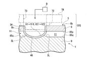
- FIG. 9 is a cross-sectional view illustrating a basic configuration of the system SYS.
- the system SYS includes the above-described fluid device 1 and the driving unit TR.
- the fluid device 1 is used by being set in the drive unit TR.
- the drive unit TR is formed in a plate shape, and is arranged to face the upper surface 6b of the first base material when the fluid device 1 is set.
- the drive section TR has a contact section 72 that contacts the upper surface 6b of the first base member 6 when the fluid device 1 is set.
- the contact portion 72 is formed in an annular shape surrounding the periphery of the valve holding hole 34. When the contact portion 72 contacts the upper surface 6b of the first base member 6, the contact portion 72 can hermetically seal the space between the contact portion 72 and the upper surface 6b.
- the drive unit TR has a drive fluid supply hole (supply unit) 73 for supplying a drive fluid to the valves V1 to V16 and V21 to V22 of the fluid device 1.
- the driving fluid supply hole 73 is supplied with a driving fluid (for example, air) from a fluid supply source D.
- the driving fluid is a force for deforming the valves V1 to V16 and V21 to V22.
- the drive unit TR supplies the utilities for driving the element pumps Pe of the second flow paths 120A to 120E via the supply paths arranged along the straight lines L1 to L3 shown in FIG. (Not shown).
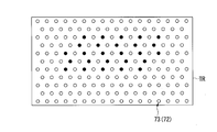
- FIG. 10 is a plan view of the driving unit TR.
- the drive section TR has a plurality of contact sections 72 and a drive fluid supply hole 73.
- the drive fluid can be independently supplied to each drive fluid supply hole 73 from the fluid supply source D.
- a predetermined number (182 in FIG. 10) of the contact portions 72 and the driving fluid supply holes 73 are arranged in a two-dimensional hexagonal lattice pattern.
- the center positions of the valves V1 to V16 and V21 to V22 in the fluid device 1 are selected from the contact portions 72 and the driving fluid supply holes 73 arranged in a two-dimensional hexagonal lattice pattern (shown in black in FIG. 10). Position).
- the fluid device 1 is set in the drive unit TR, and the drive fluid is supplied from the fluid supply source D in accordance with the opening and closing of the valves V1 to V16 and V21 to V22.
- the introduction of the solution SA into the flow channel 110 (quantification units GB1 to GB5), the introduction of the solution SB into the second flow channel 120A excluding the quantification unit GB1, and the mixing of the solutions SA and SB in the second flow channel 120A can be performed. .
- the valves V1 to V16 and V21 to V22 of the fluid device 1 are arranged at positions selected from the contact portions 72 and the driving fluid supply holes 73 arranged in a two-dimensional hexagonal lattice pattern.
- the flow path 11 and the merging / branching parts GB11 and GB12 in the fluid device 1 are not limited to the arrangement and the number thereof. Optimum flow path design that can suppress the occurrence of blemishes becomes possible.
- the arrangement and the number of the flow paths, the merging / branching parts, and the valves exemplified in the above embodiment are merely examples, and as described above, the contact parts 72 and the driving fluid supply holes 73 arranged in a two-dimensional hexagonal lattice pattern.
- a configuration is exemplified in which the contours of the merging / branching portions GB11 and GB12 are parallel to the line connecting the vertexes of the equilateral triangle in which the center positions of the valves V1 to V16 and V21 to V22 are arranged.
- the configuration is not limited to this configuration.
- the configuration may be a configuration in which the contour is a line segment connecting vertex positions.
- the configuration in which the first portion 121 of the second flow paths 120A to 120E is provided on the upper surface 9b of the second substrate 9 and the second portion 122 is provided on the lower surface 9a of the second substrate 9 has been exemplified.
- the present invention is not limited to this configuration.
- the structure provided in both may be sufficient.
- the second portion 122 also has a structure provided on the upper surface 8b of the third substrate 8 or the lower surface 9a of the second substrate 9 and the upper surface 8b of the third substrate 8 with the second portion 122 straddling the second boundary surface 62.
- a configuration may be provided in both. When the groove serving as the flow path is provided on only one of the substrates, processing and alignment between the substrates are facilitated.
- FIG. 11 is a partial plan view showing a modified example in which solutions are merged or branched in a straight flow path in the second flow path 120A and the first flow path 110, which are representative of the second flow paths 120A to 120E. It is.
- the first flow path 110 is formed of a linear flow path extending in the X direction, and the valves V1 and V4 are arranged at intervals.
- a fixed portion GB1 is formed between the valves V1 and V4.
- the + Y side end of the linear upper surface flow path 131 in which the connection hole 134 and the pump P are arranged, and the linear upper surface flow path 132 in which the connection hole 135 is formed at the + Y side end. Is connected to the end on the ⁇ Y side.
- the upper surface flow channel 131 and the upper surface flow channel 132 that constitute the first portion 121 are respectively extended in the Y direction and are spaced apart in the X direction.
- a valve V2 is arranged in the upper surface channel 131 near the quantitative section GB1.
- An introduction channel 161 having one end connected to the valve V21 is connected between the pump P and the valve V2 in the upper surface channel 131.
- a valve V3 is disposed in the upper surface flow path 132 near the quantitative section GB1.
- a discharge flow path 162 having one end connected to the valve V22 is connected between the connection hole 135 in the upper surface flow path 132 and the valve V3.
- the lower surface channel 133 constituting the second portion 122 has the same position in the X direction as the upper surface channel 131 and is arranged so as to overlap in the stacking direction.
- the connection hole 135 penetrates through the second substrate 9 inclining with respect to the lamination direction (inclination about the Y axis with respect to the Z axis), and connects the + Y side ends of the upper surface flow channel 132 and the lower surface flow channel 133 to each other.
- the second flow path 120A excluding the quantitative section GB1 is formed in a plane substantially parallel to the YZ plane.
- the other second flow paths 120B to 120E have the same configuration as the second flow path 120A.
- valves V2 and V3 by closing the valves V2 and V3 and introducing the solution SA into the first flow path 110 with the valves V1 and V4 open, the valves V1 and V4 are closed.
- a predetermined amount of the solution SA is quantified by the quantification unit GB1.
- the upper flow path 131, the connection hole 134, the lower flow path 133, the connection hole 135, and the upper flow path 132 are passed through the introduction flow path 161.
- the solution SB is quantified by partitioning a region excluding the quantification unit GB1 in the second flow path 120A.
- the solution SA is quantified to the quantification part GB1, and the solution SA, SB in the second flow path 120A is sent using the pump P in a state where the solution SB is quantified to the second flow path 120A excluding the quantification part GB1.
- the solutions SA and SB can be mixed by the small fluid device 1 in which the second flow paths 120A to 120E are formed in a plane substantially parallel to the YZ plane.
Landscapes
- Chemical & Material Sciences (AREA)
- Health & Medical Sciences (AREA)
- General Health & Medical Sciences (AREA)
- Analytical Chemistry (AREA)
- Life Sciences & Earth Sciences (AREA)
- Physics & Mathematics (AREA)
- Biochemistry (AREA)
- General Physics & Mathematics (AREA)
- Immunology (AREA)
- Pathology (AREA)
- Hematology (AREA)
- Clinical Laboratory Science (AREA)
- Chemical Kinetics & Catalysis (AREA)
- Dispersion Chemistry (AREA)
- Automatic Analysis And Handling Materials Therefor (AREA)
Abstract
L'objectif de la présente invention est de fournir un dispositif à fluide compact. L'invention concerne un dispositif à fluide comprenant : des premier à troisième substrats qui sont séquentiellement stratifiés dans la direction de l'épaisseur ; et une pluralité de passages d'écoulement de circulation ayant un premier passage d'écoulement qui est formé à partir d'une rainure disposée sur au moins l'un des premier et second substrats, une première section qui est formée à partir d'une rainure prévue sur au moins l'un des premier et second substrats et qui comprend une section partagée qui est un passage d'écoulement partiel partagé avec le premier passage d'écoulement, une seconde section qui est formée à partir d'une rainure prévue sur au moins l'un des second et troisième substrats, et une troisième section qui pénètre dans le second substrat dans la direction de l'épaisseur et relie les première et seconde sections à des positions sur les deux côtés d'extrémité.
Priority Applications (3)
| Application Number | Priority Date | Filing Date | Title |
|---|---|---|---|
| PCT/JP2018/024911 WO2020003521A1 (fr) | 2018-06-29 | 2018-06-29 | Dispositif à fluide, système et procédé de mélange |
| US17/256,542 US20220003644A1 (en) | 2018-06-29 | 2018-06-29 | Fluidic device, system, and mixing method |
| JP2020527152A JP7070679B2 (ja) | 2018-06-29 | 2018-06-29 | 流体デバイス及びシステム並びに混合方法 |
Applications Claiming Priority (1)
| Application Number | Priority Date | Filing Date | Title |
|---|---|---|---|
| PCT/JP2018/024911 WO2020003521A1 (fr) | 2018-06-29 | 2018-06-29 | Dispositif à fluide, système et procédé de mélange |
Publications (1)
| Publication Number | Publication Date |
|---|---|
| WO2020003521A1 true WO2020003521A1 (fr) | 2020-01-02 |
Family
ID=68986358
Family Applications (1)
| Application Number | Title | Priority Date | Filing Date |
|---|---|---|---|
| PCT/JP2018/024911 Ceased WO2020003521A1 (fr) | 2018-06-29 | 2018-06-29 | Dispositif à fluide, système et procédé de mélange |
Country Status (3)
| Country | Link |
|---|---|
| US (1) | US20220003644A1 (fr) |
| JP (1) | JP7070679B2 (fr) |
| WO (1) | WO2020003521A1 (fr) |
Families Citing this family (1)
| Publication number | Priority date | Publication date | Assignee | Title |
|---|---|---|---|---|
| WO2020003520A1 (fr) * | 2018-06-29 | 2020-01-02 | 株式会社ニコン | Dispositif et système fluidique |
Citations (4)
| Publication number | Priority date | Publication date | Assignee | Title |
|---|---|---|---|---|
| JP2002532710A (ja) * | 1998-12-16 | 2002-10-02 | ユーティー−バトル,エルエルシー | 電圧源と流体リザーバの数を削減する動電操作を実行する微小流体回路設計 |
| WO2015046263A1 (fr) * | 2013-09-25 | 2015-04-02 | 国立大学法人東京大学 | Mélangeur de solution, dispositif pour fluides, et procédé de mélange de solution |
| WO2017213123A1 (fr) * | 2016-06-07 | 2017-12-14 | 国立大学法人東京大学 | Dispositif à fluide |
| WO2017213080A1 (fr) * | 2016-06-06 | 2017-12-14 | 株式会社ニコン | Dispositif de fluide, système, procédé de détection de substance d'échantillon et procédé de purification de substance d'échantillon |
Family Cites Families (14)
| Publication number | Priority date | Publication date | Assignee | Title |
|---|---|---|---|---|
| DE19511603A1 (de) * | 1995-03-30 | 1996-10-02 | Norbert Dr Ing Schwesinger | Vorrichtung zum Mischen kleiner Flüssigkeitsmengen |
| JP2005326392A (ja) | 2004-04-15 | 2005-11-24 | Tama Tlo Kk | 試料導入マイクロデバイス |
| US20050272144A1 (en) | 2004-06-08 | 2005-12-08 | Konica Minolta Medical & Graphic, Inc. | Micro-reactor for improving efficiency of liquid mixing and reaction |
| JP4419760B2 (ja) | 2004-09-02 | 2010-02-24 | 株式会社島津製作所 | 分取用の電気泳動マイクロチップ装置 |
| JP2006346671A (ja) * | 2005-05-16 | 2006-12-28 | Dainippon Screen Mfg Co Ltd | 液液界面反応装置 |
| JP4880944B2 (ja) | 2005-08-11 | 2012-02-22 | セイコーインスツル株式会社 | 液体移動装置、マイクロリアクタ、およびマイクロリアクタシステム |
| US8337777B2 (en) | 2006-06-28 | 2012-12-25 | Applied Biosystems, Llc | Sample distribution devices and methods |
| NL1032816C2 (nl) * | 2006-11-06 | 2008-05-08 | Micronit Microfluidics Bv | Micromengkamer, micromenger omvattende meerdere van dergelijke micromengkamers, werkwijzen voor het vervaardigen daarvan, en werkwijzen voor mengen. |
| EP3088076A4 (fr) * | 2013-12-27 | 2017-08-30 | ASAHI FR R&D Co., Ltd. | Puce microchimique tridimensionnelle |
| EP3190169A4 (fr) * | 2014-09-02 | 2018-03-21 | Toshiba Medical Systems Corporation | Cassette de détection d'acides nucléiques |
| CN108369238A (zh) | 2015-09-25 | 2018-08-03 | 惠普发展公司,有限责任合伙企业 | 用于微流控设备的流体通道 |
| CN108291184B (zh) * | 2015-12-01 | 2022-07-01 | 日本板硝子株式会社 | Pcr反应容器、pcr装置、pcr方法 |
| JP7036126B2 (ja) * | 2017-12-28 | 2022-03-15 | 株式会社ニコン | 流体デバイスおよび流路供給システム |
| JP7151766B2 (ja) * | 2018-06-29 | 2022-10-12 | 株式会社ニコン | 流体デバイス、システム及び混合方法 |
-
2018
- 2018-06-29 WO PCT/JP2018/024911 patent/WO2020003521A1/fr not_active Ceased
- 2018-06-29 US US17/256,542 patent/US20220003644A1/en not_active Abandoned
- 2018-06-29 JP JP2020527152A patent/JP7070679B2/ja not_active Expired - Fee Related
Patent Citations (4)
| Publication number | Priority date | Publication date | Assignee | Title |
|---|---|---|---|---|
| JP2002532710A (ja) * | 1998-12-16 | 2002-10-02 | ユーティー−バトル,エルエルシー | 電圧源と流体リザーバの数を削減する動電操作を実行する微小流体回路設計 |
| WO2015046263A1 (fr) * | 2013-09-25 | 2015-04-02 | 国立大学法人東京大学 | Mélangeur de solution, dispositif pour fluides, et procédé de mélange de solution |
| WO2017213080A1 (fr) * | 2016-06-06 | 2017-12-14 | 株式会社ニコン | Dispositif de fluide, système, procédé de détection de substance d'échantillon et procédé de purification de substance d'échantillon |
| WO2017213123A1 (fr) * | 2016-06-07 | 2017-12-14 | 国立大学法人東京大学 | Dispositif à fluide |
Also Published As
| Publication number | Publication date |
|---|---|
| JPWO2020003521A1 (ja) | 2021-07-15 |
| US20220003644A1 (en) | 2022-01-06 |
| JP7070679B2 (ja) | 2022-05-18 |
Similar Documents
| Publication | Publication Date | Title |
|---|---|---|
| US11565259B2 (en) | Microfluidic devices having isolation pens and methods of testing biological micro-objects with same | |
| US10775368B2 (en) | Fluidic device, system, and method | |
| US11192106B2 (en) | Fluidic device, system, method of detecting sample material and method of purifying sample material | |
| US20180001320A1 (en) | Fluidic device, system, and method | |
| US20190099752A1 (en) | Fluidic device | |
| JP7151766B2 (ja) | 流体デバイス、システム及び混合方法 | |
| JP7070679B2 (ja) | 流体デバイス及びシステム並びに混合方法 | |
| JP7196916B2 (ja) | 流体デバイス及びシステム | |
| JP7226444B2 (ja) | 流体デバイス及びシステム | |
| US20210208175A1 (en) | Fluid device | |
| US11504712B2 (en) | Fluid device and fluid control system | |
| EP3629020B1 (fr) | Procédé et appareil de dosage de gouttelettes microfluidiques | |
| KR102458206B1 (ko) | 농도 구배 소자 | |
| US11369959B2 (en) | Fluidic device | |
| US20210162404A1 (en) | Fluid device | |
| US9475016B2 (en) | Fluid mixing structure | |
| KR20250087341A (ko) | 마이크로입자 웰을 구비한 다중진단용 칩 | |
| WO2023021951A1 (fr) | Dispositif de dosage | |
| HK1228441B (en) | Microfluidic devices having isolation pens and methods of testing biological micro-objects with same |
Legal Events
| Date | Code | Title | Description |
|---|---|---|---|
| 121 | Ep: the epo has been informed by wipo that ep was designated in this application |
Ref document number: 18924041 Country of ref document: EP Kind code of ref document: A1 |
|
| ENP | Entry into the national phase |
Ref document number: 2020527152 Country of ref document: JP Kind code of ref document: A |
|
| NENP | Non-entry into the national phase |
Ref country code: DE |
|
| 122 | Ep: pct application non-entry in european phase |
Ref document number: 18924041 Country of ref document: EP Kind code of ref document: A1 |