WO2020003530A1 - Matrice plate - Google Patents
Matrice plate Download PDFInfo
- Publication number
- WO2020003530A1 WO2020003530A1 PCT/JP2018/024924 JP2018024924W WO2020003530A1 WO 2020003530 A1 WO2020003530 A1 WO 2020003530A1 JP 2018024924 W JP2018024924 W JP 2018024924W WO 2020003530 A1 WO2020003530 A1 WO 2020003530A1
- Authority
- WO
- WIPO (PCT)
- Prior art keywords
- flat die
- grooves
- groove
- rod
- gradually
- Prior art date
- Legal status (The legal status is an assumption and is not a legal conclusion. Google has not performed a legal analysis and makes no representation as to the accuracy of the status listed.)
- Ceased
Links
Images


Classifications
-
- B—PERFORMING OPERATIONS; TRANSPORTING
- B21—MECHANICAL METAL-WORKING WITHOUT ESSENTIALLY REMOVING MATERIAL; PUNCHING METAL
- B21H—MAKING PARTICULAR METAL OBJECTS BY ROLLING, e.g. SCREWS, WHEELS, RINGS, BARRELS, BALLS
- B21H3/00—Making helical bodies or bodies having parts of helical shape
- B21H3/02—Making helical bodies or bodies having parts of helical shape external screw-threads ; Making dies for thread rolling
- B21H3/06—Making by means of profiled members other than rolls, e.g. reciprocating flat dies or jaws, moved longitudinally or curvilinearly with respect to each other
Definitions
- the present invention relates to a flat die for rolling and forming a screw component having a spiral crest, and more particularly to a flat die for manufacturing a tapping screw in which the height of a crest located at the tip of the screw component is gradually reduced. .
- a conventional flat die is formed so that a screw part can be manufactured by rolling a helically extending crest on the outer periphery of a rod-shaped material.
- the bar-shaped material before rolling, is provided integrally with a head having a cross-shaped hole and a shaft extending downward from the head, and the shaft has the same cross-section over its entire length. The dimensions are set so that
- the conventional flat die 100 is a pair of fixed die and movable die arranged opposite to each other, and the opposing surfaces thereof have a V-shaped cross section as shown in FIGS. 3 (a) to 3 (c).
- a plurality of grooves 104 are arranged so as to be inclined.
- the opposing surface has a tapered region introduction surface 102a that is inclined so as to gradually and strongly clamp the shaft portion of the rod-shaped material to be rolled, and a flat surface that is connected to the introduction surface 102a and finishes the peak portion on the shaft portion.
- a finishing surface 102b of the region and a discharge surface 102c of a reverse taper region which is provided on the finishing surface 102b and which is gradually inclined in a direction of releasing the contact from the rolling rod-shaped material are provided.
- the introduction surface 102a includes a plurality of non-slip grooves 110 formed so as to keep rolling the rod-shaped material that has started rolling.
- the inclined grooves 104 extend toward the discharge surface 102c while keeping the V-shaped bottom height constant from the introduction surface 102a.
- Three of the inclined grooves 104 are shown in FIGS. 3 (a) and 3 (b).
- a terminal portion is provided which is gradually rounded up to the terminal portions 104b1, 104b2, and 104b3.
- a virtual straight line Ls ′ connecting the terminal ends 104b1, 104b2, and 104b3 with a two-dot chain line extends in parallel with the upper end 100b and the lower end 100a of the flat die 100. Is set.
- the head of the rod-shaped material is protruded upward from the upper end 100b, and the outer periphery of the shaft is brought into contact with the facing surface to receive the same.
- the rod-shaped material is sandwiched between the opposing surfaces of the flat die 100, and rolls in the order of the introduction surface 102a, the finished surface 102b, and the discharge surface 102c, so that a spiral crest is formed on the shaft. Change to screw parts.
- the height of the ridges occupying most of the area arranged in the axial direction is substantially constant, and the height of the ridges at the remaining tip is set to the predetermined height as described above. Then it gradually lowers. Further, in the threaded part, all the ridges have the same root diameter regardless of the height of the ridges described above. Therefore, the threaded component obtained by the conventional flat die 100 gradually shifts from a low peak on the tip side to a large peak in the process of being screwed into the work, so that it is difficult to rapidly increase the screwing torque. There is.
- the conventional flat die a plurality of terminal portions are arranged side by side along the imaginary straight line Ls' on the finishing surface, so that the terminal portion whose bottom height is gradually reduced to be filled first with the excess thickness. Therefore, the surplus meat easily overflows, and the overflowed surplus meat flows into the inclined groove which is located above and has a margin in a space having a constant bottom height.
- the conventional flat die has a problem that the springback phenomenon disclosed in Patent Document 3 is easily generated in the threaded component formed by rolling.
- the present invention provides an inclined groove formed by a plurality of threads for rolling and forming a helical ridge on a rod-shaped material, an introduction surface for inviting the rod-shaped material and starting to form the ridge, and a ridge connected to the introduction surface.
- the inclined surface is provided with a finishing surface which arranges a portion and a discharge surface which is connected to the finishing surface and is inclined so as to gradually release the contact with the crest portion.
- the terminal portion of the up-grooves have the same up-angle.
- the end of the up-groove may include a raised portion for twisting the rod-shaped material which is raised toward the discharge surface side.
- the virtual straight line passing through all the terminal ends be set to an inclination angle obtained by subtracting a lead angle relating to an outer diameter of the peak from a lead angle relating to a valley diameter of the peak.
- the up-grooves formed on the finishing surface are sequentially arranged at the lower portion toward the discharge surface side, so that the up-grooves near the introduction surface side overflow from the terminal end of the shallow up-groove. Excess surplus is located in the lower part close to the discharge surface side and can be taken in stepwise into the next deep up-groove. Therefore, the flat die according to the present invention has the advantage that it is difficult to locally concentrate excess material as in the prior art, so that it is difficult to receive excessive pressure during the rolling and the life of the flat die can be extended.
- the flat die according to the present invention receives the excess thickness stepwise into the upwardly extending groove, which is located below and has room in the space as described above, so that the so-called springback phenomenon is unlikely to occur at the crest of the transferred screw component. There is also the advantage of becoming.
- the flat die according to the present invention since all the terminal portions have the same up angle, all the terminal portions have the same shape. As described above, the flat die according to the present invention can cut the end portions having the same shape by drawing the same cutter tool and the same processing trajectory, so that a plurality of processing programs for the end portions can be shared. Therefore, there is an advantage that it is difficult to complicate the creation of the machining program and the machining cost of the flat die can be reduced.
- the flat die according to the present invention since the flat die according to the present invention includes a raised portion in which the area of the up-groove formed on the finished surface is raised toward the discharge surface side, the tip of the shaft of the rod-shaped material is formed by the raised portion. Can be sharpened and twisted. Therefore, the flat die according to the present invention also has an advantage that it can be applied to the rolling of threaded parts such as one kind, two kinds, three kinds, and four kinds of tappings having a sharp point.
- the flat die according to the present invention finishes by setting an inclination angle of the virtual straight line based on an angle obtained by subtracting a lead angle relating to an outer diameter of the peak from a lead angle relating to a valley diameter of the peak.
- a plurality of terminations arranged on the surface can be arranged so as to be positioned downward toward the discharge surface side. Therefore, there is also an advantage that the arrangement of the terminal ends can be determined from the dimensions specified for the screw to be rolled.
- a flat die 1 according to the present invention is connected to an introduction surface 2a inclined from the rear end 1c to the front end 1d so as to gradually increase in thickness, and is connected to the introduction surface 2a. It has a finishing surface 2b extending toward the front end 1d, and a discharge surface 2c connected to the finishing surface 2b and inclined toward the front end 1d so as to gradually decrease its thickness.
- a plurality of V-shaped inclined grooves 4 extending in a direction from the rear end 1c side to the front end 1d side and from the upper end 1b side to the lower end 1a side are arranged.
- the inclined grooves 4 are cut by a rotary cutter having a V-shaped cutting edge.
- the plurality of inclined grooves 4 are provided with a regular groove having a constant bottom height h from the start end to the end, and an end portion cut up so as to gradually increase the bottom height (h). It is configured separately from the up-groove provided.
- the above-mentioned up-groove is provided with ends 4b1, 4b2, 4b3 which are rounded up from a fixed bottom height (h) by a predetermined up-angle ⁇ , and the above-mentioned end portions are as shown in FIG. 1 (a). Each of them is formed in the area of the finishing surface 2b.
- the plurality of up-grooves are set at a constant bottom height (h), and the bottom height (h) is the closest to the introduction surface 2a. Are set to be higher than those related to the ends 4b2 and 4b3.
- both the ends 4b2 and 4b3 have the same bottom height h and are rounded up at the same up angle ⁇ , so that both have the same volume and the same shape.
- the end portions relating to the end portions 4b1, 4b2, 4b3 are arranged so as to be closer to the lower end 1a as the position is closer to the discharge surface 2c side.
- the distance L2 from the bottom height of the terminal end of the terminal end 4b3 closest to the discharge surface 2c side to the upper end 1b is equal to the terminal end of the terminal end 4b2 close to the introduction surface 2a side. It is slightly longer than the distance L1 from the bottom height to the upper end 1b.
- a virtual straight line Ls connecting all of these ends 4b1, 4b2, 4b3 is formed from the introduction surface 2a to the discharge surface 2c and from the upper end 1b to the lower end 1a.
- the inclination angle ⁇ is set in advance. As a result, the position of the terminal end of each up-groove is determined.
- the inclination angle ⁇ of the virtual straight line Ls is set in advance in an angle range of 0 degrees 30 minutes to 1 degrees 30 minutes, but the inclination angle ⁇ calculated from the pitch and the valley diameter of the crest obtained by rolling is also included.
- the angle may be set based on the two lead angles and the first lead angle calculated from the pitch and the outer diameter of the peaks.
- the first lead angle or the second lead angle is obtained by dividing the pitch of the crest by the outer diameter or the valley diameter of the crest, dividing the divided value by a pi, It is determined from the arc tangent (ArcTan: arc tangent) of the value divided by the ratio ⁇ . Thereafter, an angle obtained by subtracting the first lead angle from the calculated second lead angle may be set as the inclination angle ⁇ .
- the cut-up position of the terminal end can be set based on the size of the screw to be rolled, and the positions of the terminal ends 4b1, 4b2, and 4b3 can be set. Can be easily set.
- the two flat dies 1 according to the present invention are opposed to each other with a predetermined gap therebetween so as to face each other, and at least one of the flat dies 1 relatively moves in the front-rear direction while maintaining the gap.
- the flat die 1 relatively moves forward, the separately supplied bar-shaped material is sandwiched by the opposing surfaces and rolls in the order of the introduction surface 2a, the finished surface 2b, and the discharge surface 2c in this order. It is gradually deformed and rolled into a spiral crest on its outer periphery.
- the flat die 1 has the ends 4b1, 4b2, and 4b3 of the inclined groove 4 arranged on the lower end 1a side in order as approaching the discharge surface 2c side.
- the crest rolls toward the front end 1d of the finished surface 2b, it moves from the raised groove at the end 4b2 to the raised groove at the end 4b3 located closer to the lower end 1a.
- the ridge in the middle of the molding which is rolling toward the discharge surface 2c side, is located below and fits into the up-groove having a deep bottom, so that the helical ridge finally obtained is On the finished surface 2b, it is roll-formed so as to become gradually longer in the axial direction.
- the flat die 1 according to the present invention can be moved in the first half of the finished surface 2b and the excess thickness of the shaft portion overflowing from the terminal portion can be moved to the next deep terminal portion located below, so that the conventional flat die 1 can be used. It is possible to prevent the concentration of excessive local excess. As a result, it is possible to roll form a ridge that is unlikely to cause a springback phenomenon, which has been a problem in the related art, and to finish the outer diameter of the ridge within the range of the standard dimension value.
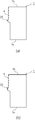
- the flat die 1 according to the present invention includes a raised portion 20 in which the region of the terminal portion is raised as approaching the discharge surface 2c as shown in FIGS. 2 (a) and 2 (b). Is also good.
- the tip of the rolled screw component can be finished to a pointed shape in the latter half of the finished surface 2b. Therefore, the flat die 1 according to the present invention is not limited to the above-described threaded part in which the valley diameter of the crest is all the same over the entire length of the shaft portion, and also the sharpness in which the trough diameter of the crest at the tip is gradually reduced. Screw parts such as the above-mentioned tapping types 1, 2, 3, and 4 can also be roll formed.
Landscapes
- Engineering & Computer Science (AREA)
- Mechanical Engineering (AREA)
- Electrical Discharge Machining, Electrochemical Machining, And Combined Machining (AREA)
Abstract
Le problème décrit par la présente invention est de fournir une matrice plate qui peut réduire la concentration locale d'une surépaisseur. La solution selon l'invention porte sur une matrice plate (1) qui comporte : une pluralité de rainures inclinées destinées à former par laminage une crête en forme de spirale sur un matériau de base en forme de tige ; une surface d'introduction destinée à guider le matériau de base en forme de tige ; une surface de finition destinée à régler la partie de crête ; et une surface de sortie inclinée de façon à libérer progressivement un contact avec la partie de crête. Les rainures inclinées sont composées de rainures régulières qui s'étendent à une hauteur inférieure fixe, et de rainures raccourcies comportant chacune une section d'extrémité terminale qui est progressivement raccourcie vers son extrémité terminale. Une pluralité des sections d'extrémité terminale des rainures raccourcies sont agencées dans une zone de la surface de finition, et disposées de façon à se déplacer séquentiellement vers le bas à l'approche du côté de la surface de sortie. Grâce à ladite configuration, la surépaisseur à partir des rainures inclinées se prolonge graduellement jusqu'à la rainure la plus profonde suivante positionnée au-dessous. Ainsi, la surépaisseur est résistante à une concentration locale, et par conséquent le phénomène de retour élastique d'un élément de vis laminé ne se produit pas facilement.
Priority Applications (2)
| Application Number | Priority Date | Filing Date | Title |
|---|---|---|---|
| PCT/JP2018/024924 WO2020003530A1 (fr) | 2018-06-29 | 2018-06-29 | Matrice plate |
| TW108113707A TWI766157B (zh) | 2018-06-29 | 2019-04-19 | 平模 |
Applications Claiming Priority (1)
| Application Number | Priority Date | Filing Date | Title |
|---|---|---|---|
| PCT/JP2018/024924 WO2020003530A1 (fr) | 2018-06-29 | 2018-06-29 | Matrice plate |
Publications (1)
| Publication Number | Publication Date |
|---|---|
| WO2020003530A1 true WO2020003530A1 (fr) | 2020-01-02 |
Family
ID=68984790
Family Applications (1)
| Application Number | Title | Priority Date | Filing Date |
|---|---|---|---|
| PCT/JP2018/024924 Ceased WO2020003530A1 (fr) | 2018-06-29 | 2018-06-29 | Matrice plate |
Country Status (2)
| Country | Link |
|---|---|
| TW (1) | TWI766157B (fr) |
| WO (1) | WO2020003530A1 (fr) |
Citations (5)
| Publication number | Priority date | Publication date | Assignee | Title |
|---|---|---|---|---|
| JPS56105842A (en) * | 1980-01-25 | 1981-08-22 | Toopura:Kk | Thread rolling method for screw |
| DE3823834A1 (de) * | 1988-07-14 | 1990-01-18 | J Vom Cleff A Sohn Gmbh & Co | Schraube, insbesondere holzschraube, verfahren zum herstellen einer schraube sowie vorrichtung zum durchfuehren des verfahrens |
| JPH05280519A (ja) * | 1992-03-17 | 1993-10-26 | Adolf Wuerth Gmbh & Co Kg | ねじとその製造方法及びその製造に用いる転造ダイス |
| JP3194977U (ja) * | 2014-10-09 | 2014-12-18 | 力鋼精密企業有限公司 | 耐摩耗性を有する転造平ダイス |
| WO2017158853A1 (fr) * | 2016-03-18 | 2017-09-21 | 株式会社三秀 | Filière plate de calandrage pour élément de vis et procédé de travail de calandrage |
Family Cites Families (2)
| Publication number | Priority date | Publication date | Assignee | Title |
|---|---|---|---|---|
| CN85102977B (zh) * | 1985-04-20 | 1988-08-24 | 夸姆克公司 | 切割型滚丝平模 |
| AU738734B2 (en) * | 1997-08-08 | 2001-09-27 | Pcc Specialty Products, Inc. | Flat thread rolling die for pointed screws |
-
2018
- 2018-06-29 WO PCT/JP2018/024924 patent/WO2020003530A1/fr not_active Ceased
-
2019
- 2019-04-19 TW TW108113707A patent/TWI766157B/zh active
Patent Citations (5)
| Publication number | Priority date | Publication date | Assignee | Title |
|---|---|---|---|---|
| JPS56105842A (en) * | 1980-01-25 | 1981-08-22 | Toopura:Kk | Thread rolling method for screw |
| DE3823834A1 (de) * | 1988-07-14 | 1990-01-18 | J Vom Cleff A Sohn Gmbh & Co | Schraube, insbesondere holzschraube, verfahren zum herstellen einer schraube sowie vorrichtung zum durchfuehren des verfahrens |
| JPH05280519A (ja) * | 1992-03-17 | 1993-10-26 | Adolf Wuerth Gmbh & Co Kg | ねじとその製造方法及びその製造に用いる転造ダイス |
| JP3194977U (ja) * | 2014-10-09 | 2014-12-18 | 力鋼精密企業有限公司 | 耐摩耗性を有する転造平ダイス |
| WO2017158853A1 (fr) * | 2016-03-18 | 2017-09-21 | 株式会社三秀 | Filière plate de calandrage pour élément de vis et procédé de travail de calandrage |
Also Published As
| Publication number | Publication date |
|---|---|
| TW202000334A (zh) | 2020-01-01 |
| TWI766157B (zh) | 2022-06-01 |
Similar Documents
| Publication | Publication Date | Title |
|---|---|---|
| CA1110474A (fr) | Vis autotaraudeuse a cone etage, et matrice de filetage pour sa fabricaton | |
| US3463045A (en) | Drilling screw | |
| US3395603A (en) | Rotary threaded fasteners | |
| US3875780A (en) | Method of making a thread forming screw | |
| US3209383A (en) | Fluted lobular thread-forming members | |
| US7101134B2 (en) | Fastener having multiple lobed thread | |
| JPS584207B2 (ja) | ネジヤマスエコミネジ | |
| US20030078109A1 (en) | Thread forming tap | |
| CN104936733A (zh) | 螺纹成型工具 | |
| EP0139195B1 (fr) | Procédé pour la fabrication des vis et outil correspondant | |
| US3550255A (en) | Method of making rotary threaded fasteners | |
| CN113369606A (zh) | 一种薄型电极的加工方法 | |
| KR101804720B1 (ko) | 절삭 탭 | |
| US6956181B2 (en) | Method for making a fastener | |
| US4655073A (en) | Thread rolling die for self-tapping screw | |
| JP3604325B2 (ja) | 棒先付きねじ用転造ダイス | |
| JP6876791B2 (ja) | 盛上げタップ | |
| US6708544B2 (en) | Thread rolling die and process for the production thereof | |
| US2165009A (en) | Die and the art of forming anchorage instruments | |
| US4368552A (en) | Method of making self tapping thread forming screw | |
| US3517542A (en) | Complementary finishing dies | |
| US4563890A (en) | Cut-off style, roll thread flat dies | |
| WO2020003530A1 (fr) | Matrice plate | |
| TWI749028B (zh) | 自攻螺釘之滾軋模 | |
| KR102708806B1 (ko) | 전조 다이스 |
Legal Events
| Date | Code | Title | Description |
|---|---|---|---|
| 121 | Ep: the epo has been informed by wipo that ep was designated in this application |
Ref document number: 18924684 Country of ref document: EP Kind code of ref document: A1 |
|
| NENP | Non-entry into the national phase |
Ref country code: DE |
|
| 122 | Ep: pct application non-entry in european phase |
Ref document number: 18924684 Country of ref document: EP Kind code of ref document: A1 |
|
| NENP | Non-entry into the national phase |
Ref country code: JP |