WO2020003565A1 - Bobine d'arrêt en mode commun - Google Patents
Bobine d'arrêt en mode commun Download PDFInfo
- Publication number
- WO2020003565A1 WO2020003565A1 PCT/JP2019/001323 JP2019001323W WO2020003565A1 WO 2020003565 A1 WO2020003565 A1 WO 2020003565A1 JP 2019001323 W JP2019001323 W JP 2019001323W WO 2020003565 A1 WO2020003565 A1 WO 2020003565A1
- Authority
- WO
- WIPO (PCT)
- Prior art keywords
- coil
- common mode
- coils
- mode choke
- parallel running
- Prior art date
- Legal status (The legal status is an assumption and is not a legal conclusion. Google has not performed a legal analysis and makes no representation as to the accuracy of the status listed.)
- Ceased
Links
Images





Classifications
-
- H—ELECTRICITY
- H01—ELECTRIC ELEMENTS
- H01F—MAGNETS; INDUCTANCES; TRANSFORMERS; SELECTION OF MATERIALS FOR THEIR MAGNETIC PROPERTIES
- H01F17/00—Fixed inductances of the signal type
- H01F17/04—Fixed inductances of the signal type with magnetic core
- H01F17/06—Fixed inductances of the signal type with magnetic core with core substantially closed in itself, e.g. toroid
- H01F17/062—Toroidal core with turns of coil around it
-
- H—ELECTRICITY
- H01—ELECTRIC ELEMENTS
- H01F—MAGNETS; INDUCTANCES; TRANSFORMERS; SELECTION OF MATERIALS FOR THEIR MAGNETIC PROPERTIES
- H01F17/00—Fixed inductances of the signal type
- H01F17/04—Fixed inductances of the signal type with magnetic core
- H01F17/06—Fixed inductances of the signal type with magnetic core with core substantially closed in itself, e.g. toroid
-
- H—ELECTRICITY
- H01—ELECTRIC ELEMENTS
- H01F—MAGNETS; INDUCTANCES; TRANSFORMERS; SELECTION OF MATERIALS FOR THEIR MAGNETIC PROPERTIES
- H01F27/00—Details of transformers or inductances, in general
- H01F27/006—Details of transformers or inductances, in general with special arrangement or spacing of turns of the winding(s), e.g. to produce desired self-resonance
-
- H—ELECTRICITY
- H01—ELECTRIC ELEMENTS
- H01F—MAGNETS; INDUCTANCES; TRANSFORMERS; SELECTION OF MATERIALS FOR THEIR MAGNETIC PROPERTIES
- H01F27/00—Details of transformers or inductances, in general
- H01F27/08—Cooling; Ventilating
- H01F27/22—Cooling by heat conduction through solid or powdered fillings
-
- H—ELECTRICITY
- H01—ELECTRIC ELEMENTS
- H01F—MAGNETS; INDUCTANCES; TRANSFORMERS; SELECTION OF MATERIALS FOR THEIR MAGNETIC PROPERTIES
- H01F27/00—Details of transformers or inductances, in general
- H01F27/28—Coils; Windings; Conductive connections
- H01F27/30—Fastening or clamping coils, windings, or parts thereof together; Fastening or mounting coils or windings on core, casing, or other support
- H01F27/306—Fastening or mounting coils or windings on core, casing or other support
-
- H—ELECTRICITY
- H01—ELECTRIC ELEMENTS
- H01F—MAGNETS; INDUCTANCES; TRANSFORMERS; SELECTION OF MATERIALS FOR THEIR MAGNETIC PROPERTIES
- H01F17/00—Fixed inductances of the signal type
- H01F2017/0093—Common mode choke coil
Definitions
- the present invention relates to a common mode choke coil provided between a power supply and a load device to reduce noise generated on the load device side and transmitted to the power supply side.
- EMI noise Electro-Magnetic Interface Noise
- inverter of the power converter Since the EMI noise becomes conduction noise and flows through the power supply line and the ground, the EMI noise may be transmitted to other electric devices and cause a malfunction, for example.
- the common mode choke coil has a common mode inductance and is mainly used to reduce common mode noise.However, it also has a normal mode inductance due to leakage magnetic flux, that is, a leakage inductance, so it is also effective in reducing normal mode noise. There is.
- a common mode choke coil is composed of a magnetic core and a pair of coils, and has a split winding configuration in which each of the pair of coils is individually wound around the magnetic core.
- the magnetic core is magnetically saturated, and the common mode inductance decreases.
- Patent Document 1 a method of suppressing magnetic saturation by winding a pair of coils by bifilar has been proposed (for example, Patent Document 1). reference).
- the present invention has been made to solve the above-described problem, and has a small size capable of suppressing magnetic saturation without extending a winding portion in a magnetic path length direction and improving a performance of reducing normal mode noise. To obtain a common mode choke coil.
- a common mode choke coil includes a magnetic core and a pair of coils wound around a winding portion of the magnetic core.
- the pair of coils each include a first pole coil and a second pole coil spirally wound N turns around the winding section in the length direction of the winding section.
- the coil and the second pole coil are arranged in the winding portion such that one or more turns of the N turns are adjacent to each other, and the adjacent first pole coil and the second pole coil are In at least one turn, there are parallel running portions overlapping each other when viewed from the length direction of the winding portion, and non-parallel running portions separated from each other in a direction orthogonal to the length direction of the winding portion.
- N is an integer of 1 or more.
- the first pole coil and the second pole coil constituting the pair of coils are arranged in the winding portion such that one or more turns out of N turns are adjacent to each other.
- magnetic saturation can be suppressed without extending the winding portion in the magnetic path length direction.
- the first pole coil and the second pole coil run parallel to each other when viewed from the longitudinal direction of the winding part.
- a non-parallel running part separated from each other in a direction perpendicular to the length direction of the winding part.
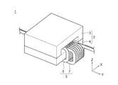
- FIG. 2 is a perspective view showing a common mode choke coil according to Embodiment 1 of the present invention.
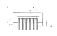
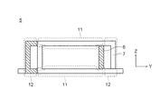
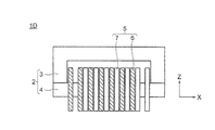
- FIG. 2 is a front view showing the common mode choke coil according to Embodiment 1 of the present invention.
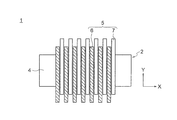
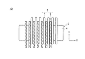
- FIG. 2 is a bottom view showing the common mode choke coil according to Embodiment 1 of the present invention.
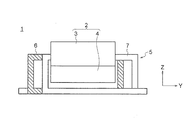
- FIG. 2 is a side view showing the common mode choke coil according to Embodiment 1 of the present invention.
- FIG. 3 is a side view showing a pair of coils in the common mode choke coil according to Embodiment 1 of the present invention.
- FIG. 2 is a schematic diagram illustrating a current flowing through a coil of the common mode choke coil according to Embodiment 1 of the present invention and a magnetic flux generated thereby.
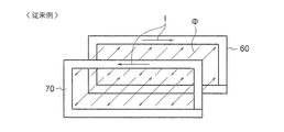
- FIG. 9 is a schematic diagram showing a magnetic flux linked from an adjacent coil in the conventional common mode choke coil disclosed in Patent Document 1.
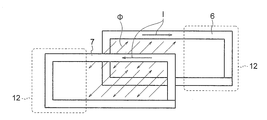
- FIG. 3 is a schematic diagram showing a magnetic flux linking from an adjacent coil in the common mode choke coil according to Embodiment 1 of the present invention.
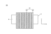
- FIG. 9 is a front view showing a common mode choke coil according to Embodiment 2 of the present invention.
- FIG. 9 is a bottom view showing a common mode choke coil according to Embodiment 2 of the present invention.
- FIG. 9 is a side view showing a pair of coils in a common mode choke coil according to Embodiment 2 of the present invention.
- FIG. 10 is a side view showing a pair of coils and a metal housing in a common mode choke coil according to Embodiment 2 of the present invention. It is a side view showing a pair of coils and a metal case in a common mode choke coil of a comparative example.
- FIG. 10 is a side view showing a common mode choke coil according to Embodiment 3 of the present invention.
- FIG. 14 is a side view showing a common mode choke coil according to Embodiment 4 of the present invention.
- FIG. 15 is a front view showing a common mode choke coil according to Embodiment 5 of the present invention.
- FIG. 15 is a bottom view showing a common mode choke coil according to Embodiment 5 of the present invention.
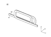
- FIG. 16 is a perspective view showing a pair of coils in a common mode choke coil according to Embodiment 6 of the present invention.
- FIG. 14 is a side view showing a pair of coils in a common mode choke coil according to Embodiment 6 of the present invention.
- FIG. FIG. 1 is a perspective view showing a common mode choke coil according to Embodiment 1 for carrying out the present invention
- FIG. 2 is a front view showing a common mode choke coil according to Embodiment 1
- FIG. FIG. 4 is a side view showing the common mode choke coil according to the first embodiment
- FIG. 5 is a side view showing the common mode choke coil according to the first embodiment. It is a side view which shows a coil.
- a common mode choke coil 1 includes a magnetic core 2 including a U-shaped core 3 and an I-shaped core 4, a positive pole coil 6 as a first pole coil, and a negative pole as a second pole coil. And a pair of coils 5 including a coil 7.
- the X direction is the direction of the magnetic path length of the magnetic core 2.
- the direction of the magnetic path length of the magnetic core 2 is the direction of the magnetic flux passing through the I-shaped core 4 which is the winding part of the pair of coils 5, and is the length direction of the I-shaped core 4.
- the Z direction is a direction orthogonal to the X direction, and is a direction in which the U-shaped core 3 is connected to the I-shaped core 4.
- the Y direction is a direction orthogonal to the X direction and the Z direction.
- the U-shaped core 3 and the I-shaped core 4 are made of a magnetic material such as ferrite.
- the magnetic core 2 is arranged such that the I-shaped core 4 connects the both leg portions of the U-shaped core 3 to constitute a closed magnetic circuit.
- the positive electrode coil 6 and the negative electrode coil 7 are formed by spirally winding a rectangular copper conductor around the I-shaped core 4 for seven turns so that the turns are alternately arranged in the X direction.
- the positive coil 6 and the negative coil 7 have the same coil shape, and are wound around the I-shaped core 4 so as to be shifted in the Y direction in FIG. As a result, as shown in FIG.
- the positive coil 6 and the negative coil 7 have a parallel running portion 11 that is an overlapping region overlapping each other and a non-parallel running portion that is a non-overlapping region that does not overlap each other, as viewed in the X direction.
- the non-overlapping region where the positive electrode coil 6 and the negative electrode coil 7 do not overlap each other when viewed from the X direction is a region where the positive electrode coil 6 and the negative electrode coil 7 are separated from each other in a direction orthogonal to the X direction.
- the X direction can also be expressed as a coil axis direction of a pair of coils 5 wound in a spiral.
- the positive coil 6 and the negative coil 7 constituting the pair of coils 5 are spirally formed on the I-shaped core 4 so that the turn portions are alternately arranged in the X direction. It is wound up. That is, the pair of coils 5 is formed by bifilar winding. Therefore, the dimension of the common mode choke coil 1 in the X direction can be reduced as compared with the conventional common mode choke coil according to Patent Documents 2 and 3, in which a bifilar winding and a split winding are used to form a pair of coils. , Miniaturization is achieved.
- FIG. 6 is a schematic diagram showing a current flowing through the coil of the common mode choke coil according to the first embodiment and a magnetic flux generated thereby.
- I indicates a current
- ⁇ indicates a magnetic flux.
- the parallel running section 11 the current I flows in opposite directions and close to the positive electrode coil 6 and the negative electrode coil 7. As a result, the magnetic flux ⁇ generated by the current I flowing through the positive coil 6 and the negative coil 7 cancel each other out, thereby suppressing the magnetic saturation of the magnetic core 2.
- the parallel running portion 11 has a small contribution to the normal mode inductance.
- the non-parallel running section 12 the current I flows in the positive coil 6 and the negative coil 7 in opposite directions and apart. As a result, a part of the magnetic flux ⁇ generated when the current I flows through the positive electrode coil 6 and the negative electrode coil 7 remains without being canceled and contributes to the normal mode inductance. However, the non-parallel running portion 12 contributes little to the suppression of the magnetic saturation of the magnetic core 2.
- the pair of coils 5 includes the parallel running portion 11 that contributes to the suppression of the magnetic saturation of the magnetic core 2 and the non-parallel running portion 12 that contributes to the normal mode inductance.
- the common mode choke coil 1 can suppress the magnetic saturation of the magnetic core 2 and improve the performance of reducing the normal mode noise.
- FIG. 7 is a schematic diagram showing the shape of the one-turn coil 8.
- Equation 1 The partial self-inductance and partial mutual inductance of the 81 turn coil 8 are expressed by Equation 1.
- i and j each take one of the values 1, 2, 3, and 4, and correspond to the section numbers shown in FIG.
- ⁇ 0 is the magnetic permeability of vacuum
- 1 is the length of the coil 8
- the coil 8 of the i-th section and the coil of the j-th section when i ⁇ j 8 is the distance.
- the loop inductance of the one-turn coil 8 is expressed by Expression 2.
- FIG. 8 is a schematic diagram showing a magnetic flux linked from an adjacent coil in a conventional common mode choke coil disclosed in Patent Document 1
- FIG. 9 is an adjacent diagram in a common mode choke coil according to the first embodiment. It is the schematic diagram which showed the magnetic flux linked from a coil. Note that the positive electrode coils 60 and 70 in FIG. 8 have the same coil shape as the positive electrode coil 6 and the negative electrode coil 7.
- Equation 3 shows the relationship between the loop inductance of the coil and the magnetic flux linking the coil.
- ⁇ is a magnetic flux linking the coil
- B is a magnetic flux density linking the coil
- s is a surface surrounded by the coil
- I is a current flowing through the coil.
- the positive coil 60 and the negative coil 70 wound in bifilar winding only have an overlapping region where they overlap each other when viewed in the X direction. That is, in the conventional common mode choke coil, the positive electrode coil 60 and the negative electrode coil 70 have only the parallel running part 11 and do not have the non-parallel running part 12. Then, as shown in FIG. 8, the current I flowing between the adjacent positive coil 60 and the negative coil 70 is in the opposite direction, and the interlinking magnetic flux ⁇ is in the opposite direction. Thereby, the magnetic flux ⁇ linking the adjacent positive coil 60 and negative coil 70 is canceled each other.
- the value of L loop that is, the normal mode inductance, is (1-n) times.
- n is 0 ⁇ n ⁇ 1.
- the adjacent positive coil 6 and the negative electrode coil 7 include the parallel running part 11 and the non-parallel running part 12, the adjacent positive coil 6 and negative electrode coil 7 The facing area is reduced by the presence of the non-parallel running portions 12.
- the facing area between the adjacent positive coil 6 and the negative coil 7 becomes m times larger than the facing area of the adjacent positive coils 60 and 70 having only the parallel portion 11. I do.
- the ratio of the canceled magnetic flux ⁇ to the total magnetic flux ⁇ linked to the adjacent positive electrode coil 6 and negative electrode coil 7 is (n ⁇ m) times.
- m is 0 ⁇ m ⁇ 1.
- the facing area between the positive coil 6 and the negative coil 7 is such that the non-parallel running portion 12 is provided so that the facing area between the positive coils 60 and 70 in Patent Document 1 is 20 mm ⁇ 50 mm. , 20 mm ⁇ 45 mm.
- m 0.9.
- the magnetic flux density B is perpendicular to the surface surrounded by the positive electrode coil 6 and the negative electrode coil 7 and is constant regardless of the position.
- the pair of coils 5 includes the positive coil 6 spirally wound around the I-shaped core 4 of the magnetic core 2 so that the turns are alternately arranged in the X direction. And a negative electrode coil 7.
- Each of the positive coil 6 and the negative coil 7 includes a parallel running portion 11 that contributes to suppression of magnetic saturation and a non-parallel running portion 12 that contributes to normal mode inductance.
- the positive coil 6 and the negative coil 7 have the same coil shape. However, the positive coil 6 and the negative coil 7 may have different coil shapes. Further, in the first embodiment, the adjacent positive coil 6 and the negative coil 7 include the parallel running portion 11 and the non-parallel running portion 12 in all of the seven turns. The negative coil 7 only needs to include the parallel running part 11 and the non-parallel running part 12 in at least one of the seven turns.
- FIG. FIG. 10 is a front view showing a common mode choke coil according to Embodiment 2 for carrying out the present invention
- FIG. 11 is a bottom view showing a common mode choke coil according to Embodiment 2
- FIG. 13 is a side view showing a pair of coils in a common mode choke coil according to Embodiment 2
- FIG. 13 is a side view showing a pair of coils and a metal housing in the common mode choke coil according to Embodiment 2
- FIG. It is a side view showing a pair of coils and a metal case in a common mode choke coil of a comparative example.
- each of the pair of coils 21 includes a positive coil 22 as a first pole coil and a negative coil 23 as a second pole coil.
- the turn portion of the positive coil 22 is configured to be larger in the Z direction than the turn portion of the negative coil 23.
- the positive electrode coil 22 and the negative electrode coil 23 are wound around the I-shaped core 4 by seven turns so that the turns are alternately arranged in the X direction.
- a metal housing 25 as a metal member is arranged on the opposite side of the U-shaped core 3 of the I-shaped core 4 in the Z direction.
- the positive electrode coil 22 and the negative electrode coil 23 are arranged such that the outer peripheral portion of the I-shaped core 4 in the Z direction opposite to the U-shaped core 3 is in contact with the metal housing 25 via the flat insulator 24. Then, it is held by the metal housing 25. Therefore, the positive coil 22 protrudes from the negative coil 23 on the side opposite to the metal housing 25 in the Z direction.
- the positive coil 22 and the negative coil 23 have a parallel running portion 11 that is an overlapping region overlapping each other and a non-parallel running portion that is a non-overlapping region that does not overlap each other, as viewed in the X direction.
- a metal material such as copper, iron, and aluminum is used for the metal housing 25, a metal material such as copper, iron, and aluminum is used.
- the other configuration is the same as that of the first embodiment.
- the positive coil 22 and the negative coil 23 are spirally wound around the I-shaped core 4 of the magnetic core 2 so that the turns are alternately arranged in the X direction.
- Each of the positive coil 22 and the negative coil 23 includes a parallel running portion 11 that contributes to suppression of magnetic saturation and a non-parallel running portion 12 that contributes to normal mode inductance. Therefore, also in the second embodiment, the same effect as in the first embodiment can be obtained.
- the non-parallel running portions 12 of the pair of coils 21 ⁇ / b> A are arranged at positions near the metal housing 25. Therefore, since the leakage magnetic flux links to the metal housing 25, the leakage magnetic flux is shielded, and the contribution to the normal mode inductance is reduced.
- the non-parallel running portions 12 of the pair of coils 21 are arranged at positions away from the metal housing 25. Therefore, since the leakage magnetic flux does not interlink with the metal housing 25, the leakage magnetic flux is not shielded, and the contribution to the normal mode inductance is increased.
- the non-parallel running portions 12 of the pair of coils 21 are arranged at positions away from the metal housing 25. Therefore, since the leakage magnetic flux in the non-parallel running portion 12 does not interlink with the metal housing 25, the improvement of the normal mode inductance becomes more effective than the case where the leakage magnetic flux interlinks with the metal housing 25.
- the metal housing 25 is disposed on the opposite side of the I-shaped core 4 of the pair of coils 21 from the U-shaped core 3. It may be arranged on the U-shaped core 3 side of the shaped core 4 or on one side of the pair of coils 21 in the Y direction. Also in this case, the non-parallel running part 12 is arranged on the opposite side of the metal casing 25 of the I-shaped core 4.
- a dedicated metal housing 25 is used as a metal member for holding the pair of coils 21.
- the metal member is a housing of a device for mounting a common mode choke coil, a common mode choke.
- a heat sink for cooling the coil, a ground of a substrate on which the common mode choke coil is mounted, or the like may be used.
- the pair of coils is held by these metal members via the insulator.
- the non-parallel running portions 12 of the pair of coils 21 may be disposed on the opposite side to the metal member such as the casing of the I-shaped core, the heat sink, and the ground of the substrate.
- FIG. FIG. 15 is a side view showing a common mode choke coil according to Embodiment 3 for carrying out the present invention.
- an auxiliary magnetic material core 30 configured as a rectangular quadrangular prism is placed in a space surrounded by the positive coil 6 and the negative coil 7 of the non-parallel running portion 12 from one end in the X direction of the space. It is inserted to reach the end.
- the other configuration is the same as that of the first embodiment.
- the positive electrode coil 6 and the negative electrode coil 7 are spirally wound around the I-shaped core 4 of the magnetic core 2 so that the turns are alternately arranged in the X direction. ing.
- Each of the positive coil 6 and the negative coil 7 includes a parallel running portion 11 that contributes to suppression of magnetic saturation and a non-parallel running portion 12 that contributes to normal mode inductance. Therefore, also in the third embodiment, the same effect as in the first embodiment can be obtained.
- the auxiliary magnetic core 30 is disposed in a space surrounded by the positive coil 6 and the negative coil 7 of the non-parallel running section 12.
- the common mode choke coil 1B according to the third embodiment is different from the first embodiment in that the auxiliary magnetic core 30 is not disposed in the space surrounded by the positive coil 6 and the negative coil 7 of the non-parallel running portion 12.
- the normal mode inductance can be more effectively improved without increasing the volume.
- the auxiliary magnetic core 30 is arranged in a space surrounded by the positive coil 6 and the negative coil 7 of the non-parallel running part 12 in the common mode choke coil 1 according to the first embodiment.
- the same effect can be obtained by arranging the auxiliary magnetic core 30 in a space surrounded by the positive coil and the negative coil of the non-parallel running part in the common mode choke coil according to another embodiment.
- the auxiliary magnetic core 30 may be made of the same magnetic material as the magnetic core 2 or may be made of a different magnetic material.
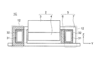
- FIG. 16 is a side view showing a common mode choke coil according to Embodiment 4 for implementing the present invention.
- a metal plate 31 which is a heat dissipating member having a rectangular quadrangular cylindrical structure, is placed in a space surrounded by the positive coil 6 and the negative coil 7 of the non-parallel running portion 12 in the X direction of the space. It is inserted from one end to the other end. Further, the metal plate 31 is inserted into the space in a state where the metal plate 31 is in contact with the inner peripheral wall surfaces of the positive coil 6 and the negative coil 7 constituting the space via the insulator 32.
- a metal material such as copper, iron, and aluminum is used for the metal plate 31.
- the other configuration is the same as that of the first embodiment.
- positive electrode coil 6 and negative electrode coil 7 are spirally wound around I-shaped core 4 of magnetic core 2 so that the turns are alternately arranged in the X direction. ing.
- Each of the positive coil 6 and the negative coil 7 includes a parallel running portion 11 that contributes to suppression of magnetic saturation and a non-parallel running portion 12 that contributes to normal mode inductance. Therefore, also in the fourth embodiment, the same effect as in the first embodiment can be obtained.
- the metal plate 31 is in contact with the positive coil 6 and the negative coil 7 via the insulator 32 in a space surrounded by the positive coil 6 and the negative coil 7 of the non-parallel running part 12.
- the common mode choke coil 1C according to the fourth embodiment is different from the first embodiment in which the metal plate 31 is not disposed in the space surrounded by the positive coil 6 and the negative coil 7 of the non-parallel running portion 12.
- the heat radiation of the pair of coils 5 can be improved without increasing the volume.
- the metal plate 31 does not shield the leakage magnetic flux generated from the non-parallel running parts 12, the effect of improving the normal mode inductance by providing the non-parallel running parts 12 is not hindered.
- the metal plate 31 is inserted into the space surrounded by the positive coil 6 and the negative coil 7 of the non-parallel running part 12 in the common mode choke coil 1 according to the first embodiment.
- the same effect can be obtained by inserting the metal plate 31 into a space surrounded by the positive coil and the negative coil of the non-parallel running part in the common mode choke coil according to another embodiment.
- the interior of the metal plate 31 is hollow.
- the metal plate 31 may be filled with a resin material, and the auxiliary magnetic core 30 according to the third embodiment may be placed in the metal plate 31. May be inserted.
- the positive electrode coil and the negative electrode coil are spirally wound around the I-shaped core by seven turns so that the turns are alternately arranged in the X direction.
- the negative coil is not limited to seven turns, and may be any number of turns.
- FIG. 17 is a front view showing a common mode choke coil according to a fifth embodiment for carrying out the present invention
- FIG. 18 is a bottom view showing a common mode choke coil according to the fifth embodiment.
- the positive coil 6 and the negative coil 7 are formed by spirally winding a copper rectangular conductor around the I-shaped core 4 so that six turns of seven turns are alternately arranged in the X direction. Have been.
- the other configuration is the same as that of the first embodiment.
- the positive coil 6 and the negative coil 7 are spirally wound around the I-shaped core 4 of the magnetic core 2 so that the turns are alternately arranged in the X direction.
- Each of the positive coil 6 and the negative coil 7 includes a parallel running portion 11 that contributes to suppression of magnetic saturation and a non-parallel running portion 12 that contributes to normal mode inductance. Therefore, also in the fifth embodiment, the same effect as in the first embodiment can be obtained.
- the positive coil 6 and the negative coil 7 are arranged on the I-shaped core 4 so as to be shifted by one turn in the X direction. That is, since the positive coil 6 and the negative coil 7 are configured using both bifilar winding and split winding, it is possible to improve the performance of reducing normal mode noise while suppressing magnetic saturation.
- the positive coil 6 and the negative coil 7 are arranged so that, of the total of 7 turns, 6 turns are alternately arranged in the X direction, and the remaining 1 turn is arranged adjacent to its own coil.
- the positive electrode coil 6 and the negative electrode coil 7 are arranged so that, of the total of seven turns, six turns are adjacent to coils of different poles, and the remaining one turn is adjacent to coils of the same pole.
- the number of turns in which coils of different poles are adjacent to each other is not limited to six, and may be any number between six and one. Further, the number of turns of the positive coil 6 and the negative coil 7 is not limited to 7 turns.
- the positive electrode coil 6 and the negative electrode coil 7 are arranged such that M turns out of all N turns are adjacent to coils of different poles, and so that (N ⁇ M) turns are adjacent to coils of the same pole. It should be done.
- N is an integer of 2 or more
- M is an integer of 1 or more and (N-1) or less.
- the normal mode inductance can be adjusted only by the ratio of the number of turns N to M. As a result, the normal mode inductance can take only discrete values.
- the normal mode inductance can be adjusted to an arbitrary value.
- the positive coil 6 and the negative coil 7 in the common mode choke coil 1 according to the first embodiment are arranged so that six turns out of a total of seven turns are alternately arranged in the X direction and remain. Although one turn is arranged so as to be adjacent to the coil of the same pole, the positive and negative coils in the common mode choke coil according to another embodiment are alternately arranged in six turns out of seven turns in the X direction. The same effect can be obtained even if the coils are arranged side by side and the remaining one turn is arranged adjacent to the coil having the same pole.
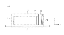
- FIG. 19 is a perspective view showing a pair of coils in a common mode choke coil according to Embodiment 6 for carrying out the present invention.
- FIG. 20 shows a pair of coils in a common mode choke coil according to Embodiment 6. It is a side view.
- the pair of coils 40 includes a positive coil 41, which is a one-turn first pole coil, and a negative coil 42, which is a one-turn second pole coil.
- the positive electrode coil 41 and the negative electrode coil 42 are wound around an I-shaped core which is a winding part of a magnetic core so as to be adjacent to each other.
- the positive electrode coil 41 and the negative electrode coil 42 include, when viewed from the X direction, a parallel running portion 11 that is an overlapping region that overlaps each other, and a non-parallel running portion 12 that is a non-overlapping region that does not overlap each other.
- the other configuration is the same as that of the first embodiment.
- the positive coil 41 and the negative coil 42 each having one turn are wound around the I-shaped magnetic core so as to be adjacent to each other in the X direction.
- the positive coil 41 and the negative coil 42 each include, in one turn, a parallel running portion 11 contributing to suppression of magnetic saturation and a non-parallel running portion 12 contributing to normal mode inductance. Therefore, also in the sixth embodiment, the same effect as in the first embodiment can be obtained.
- the effect of the present invention can be obtained even when the positive coil and the negative coil have one turn. Therefore, according to the present invention, the positive electrode coil and the negative electrode coil are spirally wound at least one turn in the longitudinal direction of the I-shaped core, and the positive electrode coil and the negative electrode coil are wound at least one turn at a time. And at least one turn between the adjacent positive and negative coils may be provided with a parallel running portion and a non-parallel running portion.
- the metal housing 25 may be arranged at a position away from the non-parallel running portions 12 of the pair of coils 40.
- the auxiliary magnetic core 30 may be inserted into a space surrounded by the positive coil 41 and the negative coil 42 of the non-parallel running portion 12.
- the metal plate 31 is provided between the positive coil 41 and the negative coil 42 via the insulator 32 in the space surrounded by the positive coil 41 and the negative coil 42 of the non-parallel part 12. May be arranged to be in contact with.
- the magnetic core composed of the U-shaped core and the I-shaped core is used.
- the magnetic core is limited to the core formed by combining the U-shaped core and the I-shaped core.
- a core combining a U-shaped core and a U-shaped core, a toroidal core, or the like may be used.
- the rectangular coil conductor made of copper is used as the material of the positive electrode coil and the negative electrode coil, but other highly conductive material, for example, a rectangular conductor made of aluminum may be used. Further, although a rectangular conductor is used as a material of the positive coil and the negative coil, a conductor having a circular cross section may be used.
- the positive electrode coil and the negative electrode coil are formed in a rectangular cylindrical coil shape, but the coil shape is not limited to the rectangular cylindrical shape.
Landscapes
- Engineering & Computer Science (AREA)
- Power Engineering (AREA)
- Microelectronics & Electronic Packaging (AREA)
- Coils Or Transformers For Communication (AREA)
- Coils Of Transformers For General Uses (AREA)
Abstract
Selon la présente invention, cette bobine d'arrêt en mode commun comprend un noyau magnétique (2), et une paire de bobines (5) enroulées sur une partie d'enroulement (4) du noyau magnétique. Chaque bobine de la paire de bobines (5) est pourvue d'une première bobine d'électrode (6) et d'une seconde bobine d'électrode (7) qui sont respectivement enroulées en N spires sur la partie d'enroulement en une forme de spirale dans la direction de la longueur de la partie d'enroulement. La première bobine d'électrode (6) et la seconde bobine d'électrode (7) sont disposées sur la partie d'enroulement (4) de telle sorte qu'une ou plusieurs spires parmi les N spires soient adjacentes l'une à l'autre. Vu depuis la direction de la longueur de la partie d'enroulement (4), au moins un tour adjacent de la première bobine d'électrode et de la seconde bobine d'électrode comprend une section de roulement parallèle (11) dans laquelle les bobines d'électrode se chevauchent, et une section de roulement non parallèle (12) dans laquelle elles se séparent l'une de l'autre dans une direction orthogonale à la direction de la longueur de la partie d'enroulement (4). N est un nombre entier de 1 ou plus.
Priority Applications (4)
| Application Number | Priority Date | Filing Date | Title |
|---|---|---|---|
| DE112019003205.4T DE112019003205T5 (de) | 2018-06-28 | 2019-01-17 | Gleichtakt-drosselspule |
| JP2019524484A JP6593834B1 (ja) | 2018-06-28 | 2019-01-17 | コモンモードチョークコイル |
| CN201980041264.2A CN112313764B (zh) | 2018-06-28 | 2019-01-17 | 共模扼流线圈 |
| US17/049,036 US11749439B2 (en) | 2018-06-28 | 2019-07-17 | Common mode choke coil |
Applications Claiming Priority (2)
| Application Number | Priority Date | Filing Date | Title |
|---|---|---|---|
| JP2018123064 | 2018-06-28 | ||
| JP2018-123064 | 2018-06-28 |
Publications (1)
| Publication Number | Publication Date |
|---|---|
| WO2020003565A1 true WO2020003565A1 (fr) | 2020-01-02 |
Family
ID=68986181
Family Applications (1)
| Application Number | Title | Priority Date | Filing Date |
|---|---|---|---|
| PCT/JP2019/001323 Ceased WO2020003565A1 (fr) | 2018-06-28 | 2019-01-17 | Bobine d'arrêt en mode commun |
Country Status (3)
| Country | Link |
|---|---|
| US (1) | US11749439B2 (fr) |
| DE (1) | DE112019003205T5 (fr) |
| WO (1) | WO2020003565A1 (fr) |
Cited By (2)
| Publication number | Priority date | Publication date | Assignee | Title |
|---|---|---|---|---|
| JP2021141223A (ja) * | 2020-03-06 | 2021-09-16 | 株式会社トーキン | リアクトル |
| WO2025134507A1 (fr) * | 2023-12-19 | 2025-06-26 | 株式会社Ihi | Circuit de filtre de mode commun |
Families Citing this family (2)
| Publication number | Priority date | Publication date | Assignee | Title |
|---|---|---|---|---|
| JP6956925B2 (ja) * | 2019-05-24 | 2021-11-02 | 三菱電機株式会社 | ノイズ低減素子 |
| JP7468275B2 (ja) * | 2020-09-29 | 2024-04-16 | 株式会社豊田自動織機 | ノイズフィルタ |
Citations (4)
| Publication number | Priority date | Publication date | Assignee | Title |
|---|---|---|---|---|
| JPH10163046A (ja) * | 1996-12-02 | 1998-06-19 | Matsushita Electric Ind Co Ltd | ノイズフィルタ |
| JP2005166791A (ja) * | 2003-12-01 | 2005-06-23 | Taiyo Yuden Co Ltd | 積層チップコモンモードチョークコイル |
| JP2007027445A (ja) * | 2005-07-15 | 2007-02-01 | Murata Mfg Co Ltd | 積層コモンモードチョークコイル |
| JP2019009152A (ja) * | 2017-06-20 | 2019-01-17 | スミダコーポレーション株式会社 | エッジワイズコイル、リアクトル及びリアクトル製造方法 |
Family Cites Families (6)
| Publication number | Priority date | Publication date | Assignee | Title |
|---|---|---|---|---|
| JPH0729755A (ja) | 1993-07-14 | 1995-01-31 | Top Denshi Kk | コモンモードチョークコイル |
| JPH11214229A (ja) | 1998-01-23 | 1999-08-06 | Kankyo Denji Gijutsu Kenkyusho:Kk | コモンモードチョークコイル |
| JP2002246244A (ja) | 2001-02-15 | 2002-08-30 | Murata Mfg Co Ltd | チョークコイル |
| US7385466B2 (en) * | 2004-03-30 | 2008-06-10 | Matsushita Electric Industrial Co., Ltd. | Differential transmission circuit and common mode choke coil |
| JP4797549B2 (ja) * | 2005-10-05 | 2011-10-19 | Tdk株式会社 | コモンモードチョークコイル及びその製造方法 |
| CN105706196B (zh) | 2013-11-08 | 2018-04-10 | 三菱电机株式会社 | 电磁感应设备 |
-
2019
- 2019-01-17 WO PCT/JP2019/001323 patent/WO2020003565A1/fr not_active Ceased
- 2019-01-17 DE DE112019003205.4T patent/DE112019003205T5/de not_active Withdrawn
- 2019-07-17 US US17/049,036 patent/US11749439B2/en active Active
Patent Citations (4)
| Publication number | Priority date | Publication date | Assignee | Title |
|---|---|---|---|---|
| JPH10163046A (ja) * | 1996-12-02 | 1998-06-19 | Matsushita Electric Ind Co Ltd | ノイズフィルタ |
| JP2005166791A (ja) * | 2003-12-01 | 2005-06-23 | Taiyo Yuden Co Ltd | 積層チップコモンモードチョークコイル |
| JP2007027445A (ja) * | 2005-07-15 | 2007-02-01 | Murata Mfg Co Ltd | 積層コモンモードチョークコイル |
| JP2019009152A (ja) * | 2017-06-20 | 2019-01-17 | スミダコーポレーション株式会社 | エッジワイズコイル、リアクトル及びリアクトル製造方法 |
Cited By (3)
| Publication number | Priority date | Publication date | Assignee | Title |
|---|---|---|---|---|
| JP2021141223A (ja) * | 2020-03-06 | 2021-09-16 | 株式会社トーキン | リアクトル |
| JP7437193B2 (ja) | 2020-03-06 | 2024-02-22 | 株式会社トーキン | リアクトル |
| WO2025134507A1 (fr) * | 2023-12-19 | 2025-06-26 | 株式会社Ihi | Circuit de filtre de mode commun |
Also Published As
| Publication number | Publication date |
|---|---|
| US20210327629A1 (en) | 2021-10-21 |
| DE112019003205T5 (de) | 2021-03-11 |
| US11749439B2 (en) | 2023-09-05 |
Similar Documents
| Publication | Publication Date | Title |
|---|---|---|
| KR0165948B1 (ko) | 초크 코일 | |
| WO2020003565A1 (fr) | Bobine d'arrêt en mode commun | |
| US11688541B2 (en) | Integrated magnetic component | |
| US20060152325A1 (en) | Magnetic core type laminated inductor | |
| US10224141B2 (en) | Coupled inductor | |
| US10804709B2 (en) | Coil unit, and power transmitting device, power receiving device and wireless power transmission system using the coil unit | |
| US20150109090A1 (en) | Electrical transformer with a shielded cast coil assembly | |
| JPH08181018A (ja) | コイル装置 | |
| CN117253700A (zh) | 变压器 | |
| JP6593834B1 (ja) | コモンモードチョークコイル | |
| US20100188184A1 (en) | Inductor and core member thereof | |
| CN113574619A (zh) | 漏磁变压器 | |
| JP2019009177A (ja) | 磁性被覆コイル及びこれを用いたトランス | |
| US20180040408A1 (en) | Reactor | |
| CN1185011A (zh) | 扼流圈 | |
| KR20040024724A (ko) | 트랜스포머 및 이를 구비하는 전기 기기 | |
| KR102735137B1 (ko) | 소형화된 가변 인덕터 | |
| JP6424710B2 (ja) | 非接触電力伝送用コイルおよび非接触電力伝送装置 | |
| JP6823130B2 (ja) | フィルタ装置 | |
| JP2002164235A (ja) | リーケージトランス、電源装置および照明器具 | |
| KR102075955B1 (ko) | 투인원 평면 인덕터 | |
| JPH08316038A (ja) | 偏平形積層トランス | |
| JP6376317B1 (ja) | アンテナ装置および電子機器 | |
| KR20230009602A (ko) | 자속 차폐 기능이 구비된 코어 타입 코일부품 | |
| JP7122137B2 (ja) | ワイヤレス給電用電気ユニット |
Legal Events
| Date | Code | Title | Description |
|---|---|---|---|
| ENP | Entry into the national phase |
Ref document number: 2019524484 Country of ref document: JP Kind code of ref document: A |
|
| 121 | Ep: the epo has been informed by wipo that ep was designated in this application |
Ref document number: 19825252 Country of ref document: EP Kind code of ref document: A1 |
|
| 122 | Ep: pct application non-entry in european phase |
Ref document number: 19825252 Country of ref document: EP Kind code of ref document: A1 |