WO2020003581A1 - Système d'opération et procédé de transfert de chariot d'alimentation - Google Patents
Système d'opération et procédé de transfert de chariot d'alimentation Download PDFInfo
- Publication number
- WO2020003581A1 WO2020003581A1 PCT/JP2019/004145 JP2019004145W WO2020003581A1 WO 2020003581 A1 WO2020003581 A1 WO 2020003581A1 JP 2019004145 W JP2019004145 W JP 2019004145W WO 2020003581 A1 WO2020003581 A1 WO 2020003581A1
- Authority
- WO
- WIPO (PCT)
- Prior art keywords
- feeder
- base
- truck
- nozzle
- mounting
- Prior art date
- Legal status (The legal status is an assumption and is not a legal conclusion. Google has not performed a legal analysis and makes no representation as to the accuracy of the status listed.)
- Ceased
Links
Images


Classifications
-
- H—ELECTRICITY
- H05—ELECTRIC TECHNIQUES NOT OTHERWISE PROVIDED FOR
- H05K—PRINTED CIRCUITS; CASINGS OR CONSTRUCTIONAL DETAILS OF ELECTRIC APPARATUS; MANUFACTURE OF ASSEMBLAGES OF ELECTRICAL COMPONENTS
- H05K13/00—Apparatus or processes specially adapted for manufacturing or adjusting assemblages of electric components
- H05K13/0084—Containers and magazines for components, e.g. tube-like magazines
-
- H—ELECTRICITY
- H05—ELECTRIC TECHNIQUES NOT OTHERWISE PROVIDED FOR
- H05K—PRINTED CIRCUITS; CASINGS OR CONSTRUCTIONAL DETAILS OF ELECTRIC APPARATUS; MANUFACTURE OF ASSEMBLAGES OF ELECTRICAL COMPONENTS
- H05K13/00—Apparatus or processes specially adapted for manufacturing or adjusting assemblages of electric components
- H05K13/04—Mounting of components, e.g. of leadless components
- H05K13/0417—Feeding with belts or tapes
- H05K13/0419—Feeding with belts or tapes tape feeders
-
- B—PERFORMING OPERATIONS; TRANSPORTING
- B66—HOISTING; LIFTING; HAULING
- B66F—HOISTING, LIFTING, HAULING OR PUSHING, NOT OTHERWISE PROVIDED FOR, e.g. DEVICES WHICH APPLY A LIFTING OR PUSHING FORCE DIRECTLY TO THE SURFACE OF A LOAD
- B66F9/00—Devices for lifting or lowering bulky or heavy goods for loading or unloading purposes
- B66F9/06—Devices for lifting or lowering bulky or heavy goods for loading or unloading purposes movable, with their loads, on wheels or the like, e.g. fork-lift trucks
- B66F9/063—Automatically guided
-
- G—PHYSICS
- G05—CONTROLLING; REGULATING
- G05B—CONTROL OR REGULATING SYSTEMS IN GENERAL; FUNCTIONAL ELEMENTS OF SUCH SYSTEMS; MONITORING OR TESTING ARRANGEMENTS FOR SUCH SYSTEMS OR ELEMENTS
- G05B19/00—Program-control systems
- G05B19/02—Program-control systems electric
- G05B19/418—Total factory control, i.e. centrally controlling a plurality of machines, e.g. direct or distributed numerical control [DNC], flexible manufacturing systems [FMS], integrated manufacturing systems [IMS] or computer integrated manufacturing [CIM]
- G05B19/41865—Total factory control, i.e. centrally controlling a plurality of machines, e.g. direct or distributed numerical control [DNC], flexible manufacturing systems [FMS], integrated manufacturing systems [IMS] or computer integrated manufacturing [CIM] characterised by job scheduling, process planning, material flow
-
- H—ELECTRICITY
- H05—ELECTRIC TECHNIQUES NOT OTHERWISE PROVIDED FOR
- H05K—PRINTED CIRCUITS; CASINGS OR CONSTRUCTIONAL DETAILS OF ELECTRIC APPARATUS; MANUFACTURE OF ASSEMBLAGES OF ELECTRICAL COMPONENTS
- H05K13/00—Apparatus or processes specially adapted for manufacturing or adjusting assemblages of electric components
- H05K13/0015—Orientation; Alignment; Positioning
-
- H—ELECTRICITY
- H05—ELECTRIC TECHNIQUES NOT OTHERWISE PROVIDED FOR
- H05K—PRINTED CIRCUITS; CASINGS OR CONSTRUCTIONAL DETAILS OF ELECTRIC APPARATUS; MANUFACTURE OF ASSEMBLAGES OF ELECTRICAL COMPONENTS
- H05K13/00—Apparatus or processes specially adapted for manufacturing or adjusting assemblages of electric components
- H05K13/08—Monitoring manufacture of assemblages
- H05K13/086—Supply management, e.g. supply of components or of substrates
-
- B—PERFORMING OPERATIONS; TRANSPORTING
- B62—LAND VEHICLES FOR TRAVELLING OTHERWISE THAN ON RAILS
- B62B—HAND-PROPELLED VEHICLES, e.g. HAND CARTS OR PERAMBULATORS; SLEDGES
- B62B3/00—Hand carts having more than one axis carrying transport wheels; Steering devices therefor; Equipment therefor
- B62B3/10—Hand carts having more than one axis carrying transport wheels; Steering devices therefor; Equipment therefor characterised by supports specially adapted to objects of definite shape
-
- G—PHYSICS
- G05—CONTROLLING; REGULATING
- G05B—CONTROL OR REGULATING SYSTEMS IN GENERAL; FUNCTIONAL ELEMENTS OF SUCH SYSTEMS; MONITORING OR TESTING ARRANGEMENTS FOR SUCH SYSTEMS OR ELEMENTS
- G05B2219/00—Program-control systems
- G05B2219/30—Nc systems
- G05B2219/50—Machine tool, machine tool null till machine tool work handling
- G05B2219/50393—Floor conveyor, AGV automatic guided vehicle
Definitions
- the present disclosure relates to a mounting system having a component mounting apparatus in which a mounting head mounts components supplied by a parts feeder on a substrate, a work system including an automatic transport system, and a transport method for a feeder cart.
- the component mounting apparatus is configured to produce a mounting board by mounting a component supplied by a parts feeder connected to a base to a substrate positioned by a substrate positioning unit after the mounting head sucks the nozzle by a nozzle. .
- the parts feeder is mounted on a feeder truck that can be connected to and separated from the base, and is connected to the base by connecting the feeder truck to the base.
- it is necessary to replace a feeder cart on which a part feeder for producing a board after the model change is set, in accordance with a board model change or the like (for example, see Patent Document 1 below).
- replacement of a feeder cart by an automatic carrier has been proposed for automation and labor saving.
- the work system is a work system including a mounting system for mounting components on a board and an automatic transport system having an automatic transport vehicle.
- the mounting system includes a base having a substrate positioning portion for positioning the substrate, a feeder truck that can be connected to and separated from the base, a connection mechanism that connects the feeder truck to the base, and an attachment to the feeder truck.
- a parts feeder for supplying parts in a state where the feeder cart is connected to the base; and a mounting head for mounting parts supplied by the parts feeder to the substrate positioned by the substrate positioning part.
- the automatic transport system notifies the mounting system of an arrival notification indicating that the automatic transport vehicle has arrived at a position where separation work for separating the feeder truck connected to the base from the base can be started.
- a first notification unit and a first processing unit that, when receiving a release notification from the mounting system indicating that the connection of the feeder truck has been released, causes the automatic guided vehicle to travel in a direction away from the base. Further, the mounting system, upon receiving the arrival notification, a second processing unit that causes the connection mechanism to perform a release operation for releasing the connection of the feeder trolley, and the automatic release notification is performed when the release operation is completed. And a second notification unit for notifying the transport system.
- the mounting system includes a base having a substrate positioning portion for positioning the substrate, a feeder truck that can be connected to and separated from the base, a connection mechanism that connects the feeder truck to the base, and the feeder truck is such that A trolley detecting means for detecting whether or not it is located at a position where connection by the connection mechanism is possible, and a parts feeder attached to the feeder trolley and supplying parts in a state where the feeder trolley is connected to the base. And a mounting head for mounting components supplied by the parts feeder to the substrate positioned by the substrate positioning unit.
- the automatic transport system notifies the mounting system of an arrival notification indicating that the automatic transport vehicle has transported the feeder truck scheduled to be connected to the base to a position where connection work with the base can be started.
- the automatic transport vehicle Upon receiving a connection notification permitting connection of the feeder truck to the base from the first notification unit and the mounting system, the automatic transport vehicle is driven to connect the feeder truck by the connection mechanism.
- the mounting system upon receiving the arrival notification, notifies the automatic transport system of the connection permission, and after the notification, when the bogie detecting means detects the feeder bogie, the connecting mechanism is operated to activate the feeder.
- a second processing unit that connects the carriage to the base; and a second notification unit that notifies the automatic transport system of the completion of the connection when the connection is completed.
- a method of transporting a feeder truck includes a base having a substrate positioning portion for positioning a substrate, a feeder truck that can be connected to and separated from the base, a connection mechanism that connects the feeder truck to the base, A parts feeder attached to the feeder cart and supplying parts in a state where the feeder cart is connected to the base, and a mounting head for attaching the parts supplied by the parts feeder to the board positioned by the board positioning section And a transport method of a feeder truck that transports the feeder truck using an automatic transport vehicle.
- the method of transporting a feeder truck includes moving the automatic transporter to a position where separation work for separating the feeder truck connected to the base from the base can be started, and controlling the automatic transporter.
- the arrival notification that the automatic carrier has arrived at a position where the separation work can be started is notified to the mounting system, and when the mounting system receives the arrival notification, the connection mechanism connects the feeder truck. And, from the mounting system, notifies the automatic transport system of a release notification that the connection of the feeder cart has been released, and when the automatic transport system receives the release notification, the automatic transport vehicle The feeder cart is moved in a direction away from the base.
- Another method of transporting a feeder truck includes a base having a substrate positioning portion for positioning a substrate, a feeder truck that can be connected to and separated from the base, and a connecting mechanism that connects the feeder truck to the base. And a parts feeder attached to the feeder cart and supplying parts in a state where the feeder cart is connected to the base; and a part supplied by the parts feeder mounted on the board positioned by the board positioning section.
- a feeder truck is transported by using an automatic transporter to transport the feeder truck.
- the method of transporting the feeder trolley includes moving the feeder trolley to be connected to the base by the automatic transporter to a position at which the feeder trolley can be connected by the connection mechanism.
- the carriage detection means detects whether or not it is located at a position where the carriage is possible, and in the mounting system, when the feeder carriage is detected, the connection mechanism is operated to connect the feeder carriage to the base, and the connection is performed. Is completed, the automatic guided vehicle is caused to travel in a direction away from the feeder truck connected to the base.
- FIG. 1 is a perspective view of a component mounting apparatus according to an embodiment of the present disclosure.
- FIG. 2 is a plan view of the component mounting apparatus according to the embodiment of the present disclosure.
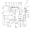
- FIG. 3 is a side view of the component mounting apparatus according to the embodiment of the present disclosure.
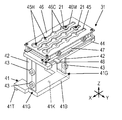
- FIG. 4 is a perspective view of a part of the component mounting apparatus according to the embodiment of the present disclosure.
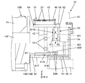
- FIG. 5 is a side view illustrating a state where the feeder cart is separated from the base of the component mounting apparatus according to the embodiment of the present disclosure.
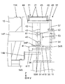
- FIG. 6 is a perspective view of a part of the base of the component mounting apparatus according to the embodiment of the present disclosure.
- FIG. 7 is a front view of the mounting head included in the component mounting apparatus according to the embodiment of the present disclosure.
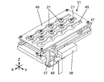
- FIG. 8 is a perspective view of a feeder cart included in the component mounting apparatus according to the embodiment of the present disclosure.
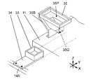
- FIG. 9 is a perspective view illustrating a state in which the nozzle replacement table is separated from the mounting table of the feeder truck included in the component mounting apparatus according to the embodiment of the present disclosure.
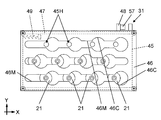
- FIG. 10A is a perspective view of a nozzle exchange table provided in the component mounting apparatus according to the embodiment of the present disclosure.
- FIG. 10B is a perspective view of a nozzle exchange table provided in the component mounting apparatus according to the embodiment of the present disclosure.
- FIG. 11A is a plan view of a nozzle exchange table provided in the component mounting apparatus according to the embodiment of the present disclosure.
- FIG. 11B is a plan view of a nozzle exchange table provided in the component mounting apparatus according to the embodiment of the present disclosure.
- FIG. 12 is a perspective view of an exchange table holding unit included in the component mounting apparatus according to the embodiment of the present disclosure.
- FIG. 13 is a cross-sectional view of a part of the exchange table holding unit included in the component mounting apparatus according to the embodiment of the present disclosure.
- FIG. 14 is a perspective view illustrating a state where the nozzle replacement table included in the component mounting apparatus according to the embodiment of the present disclosure is mounted on the mounting table.
- FIG. 15 is a side view illustrating a state where the nozzle replacement table is held in the replacement table holding unit of the component mounting apparatus according to the embodiment of the present disclosure.
- FIG. 16 is a side view illustrating a state in which the nozzle exchange table is held by the exchange table holder of the component mounting apparatus according to the embodiment of the present disclosure.
- FIG. 17 is a side view illustrating a state in which the nozzle exchange table is held by the exchange table holder of the component mounting apparatus according to the embodiment of the present disclosure.
- FIG. 18 is a side view illustrating a state where the nozzle replacement table is held in the replacement table holding unit of the component mounting apparatus according to the embodiment of the present disclosure.
- FIG. 19 is a perspective view illustrating a state in which the nozzle replacement table is held by the replacement table holder of the component mounting apparatus according to the embodiment of the present disclosure.
- FIG. 20A is a perspective view illustrating a positional relationship between the shutter operation unit and the operated piece before and after the nozzle exchange table is held by the exchange table holding unit of the component mounting apparatus according to an embodiment of the present disclosure.
- FIG. 20B is a perspective view illustrating a positional relationship between the shutter operation unit and the operated piece before and after the nozzle exchange table is held by the exchange table holder of the component mounting apparatus according to an embodiment of the present disclosure.
- FIG. 21A is a plan view of a nozzle exchange table provided in the component mounting apparatus according to the embodiment of the present disclosure.
- FIG. 21B is a plan view of the nozzle exchange table provided in the component mounting apparatus according to the embodiment of the present disclosure.
- FIG. 22A is a perspective view illustrating a state where the component disposal box of the component mounting apparatus according to the embodiment of the present disclosure is set within the movable range of the mounting head.
- FIG. 22B is a perspective view illustrating a state where the component disposal box of the component mounting apparatus according to the embodiment of the present disclosure is set within the movable range of the mounting head.
- FIG. 23 is a flowchart illustrating an example of an operation flow of the component mounting apparatus according to an embodiment of the present disclosure.
- FIG. 24 is a flowchart illustrating an example of an operation flow of the component mounting apparatus according to an embodiment of the present disclosure.
- FIG. 25 is a flowchart illustrating an example of an operation flow of the component mounting apparatus according to a modified example of the embodiment of the present disclosure.
- FIG. 23 is a flowchart illustrating an example of an operation flow of the component mounting apparatus according to an embodiment of the present disclosure.
- FIG. 26 is a diagram illustrating a configuration example of a work system including a component mounting apparatus according to an embodiment of the present disclosure.
- FIG. 27 is a flowchart illustrating an example of an operation flow of the work system including the component mounting apparatus according to the embodiment of the present disclosure.
- FIG. 28 is a flowchart illustrating an example of an operation flow of the work system including the component mounting apparatus according to the embodiment of the present disclosure.
- FIG. 29 is a diagram for describing the capturing mechanism of the automatic guided vehicle according to an embodiment of the present disclosure.
- FIG. 30 is a diagram illustrating a state where the feeder truck is lifted by the capturing mechanism according to the embodiment of the present disclosure.
- an object of the present disclosure is to provide a work system capable of exchanging a feeder truck by linking a mounting system and an automatic transport system, and a transport method of the feeder truck.
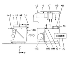
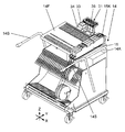
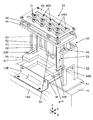
- the component mounting apparatus 1 is an apparatus for producing a component mounting board by mounting a component BH on a board KB carried in from the outside, and includes a base 11, a base cover 12, two transport conveyors 13, and two feeder carts 14. , A parts feeder 15, a head moving mechanism 16, two mounting heads 17, two component cameras 18, and the like.
- the left-right direction of the component mounting apparatus 1 is defined as an X-axis direction
- the front-rear direction is defined as a Y-axis direction
- the up-down direction is defined as a Z-axis direction.
- One side of the component mounting apparatus 1 in the front-rear direction is a front side
- the other side is a rear side.
- the two conveyors 13 include a front conveyor 13 and a rear conveyor 13. Each of the two conveyors 13 extends in the X-axis direction. Each of the two transport conveyors 13 functions as a substrate positioning unit, and transports the substrate KB loaded from the outside in the X-axis direction and positions it at a predetermined work position.
- the base cover 12 is provided so as to cover the base 11, and forms a work space 11S between the base cover 11 and the upper surface of the base 11 (FIGS. 1 and 3).
- a door portion 12C that is a part of the base cover 12 is provided (FIG. 3).
- the door 12C can be freely opened and closed in the vertical direction, and the operator OP can manually open and close it.
- the door 12 ⁇ / b> C that is open upward is indicated by a dashed line.
- the feeder cart 14 is connected to the front side and the rear side of the base 11 so as to be freely connected and separable.
- the area on the base 11 in front of the transport conveyor 13 on the front side is an equipment installation area on the front side, and the feeder truck 14 on the front side is connected to be adjacent to the front of the equipment installation area on the front side.
- the area behind the rear conveyor 13 on the base 11 is the equipment installation area on the rear side, and the feeder truck 14 on the rear side is connected adjacent to the rear of the equipment installation area on the rear side. Is done.
- each feeder truck 14 has a flat feeder base 14F.
- a parts feeder 15 is mounted on the upper surface side of the feeder base 14F.
- a plurality of parts feeders 15 can be mounted side by side in the X-axis direction on the feeder base 14F (FIGS. 2 and 4).
- the side facing the center of the base 11 with the feeder cart 14 connected to the base 11 is referred to as the “base side” of the feeder cart 14. ".
- the parts feeder 15 is detachably attached to the feeder base 14F of the feeder cart 14, and supplies the parts BH to the parts supply port 15K.
- the parts supply port 15K is positioned above the base-side end of the feeder base 14F (FIGS. 2 and 3).
- the parts feeder 15 is assumed to be a tape feeder of a type that feeds the parts BH to the parts supply port 15K by feeding the carrier tape containing the parts BH at a pitch, but the parts feeder 15 is not limited to the tape feeder. It may be a bulk feeder, a stick feeder, or the like.
- two operation units 14 ⁇ / b> S that the operator OP operates with both hands are provided on the left and right of each feeder cart 14.
- the operator OP operates the operation section 14S, approaches the base side end of the feeder base 14F so as to face the center of the base 11, and connects the feeder carriage 14 to the base 11.
- a plurality of parts feeders 15 attached to the feeder base 14F are connected to the base 11 in a lump.
- the parts supply port 15K of the parts feeder 15 is located in the work space 11S (FIG. 3). Therefore, when the parts feeder 15 connected to the base 11 sends the parts BH to the parts supply port 15K, the parts BH are supplied into the work space 11S.
- a trolley-side connector 14C protruding toward the center of the base 11 is provided at an end of the feeder trolley 14 on the base side.
- a base-side connector 11C is provided on the base 11 side. When the feeder truck 14 is connected to the base 11, the truck-side connector 14C fits into the base-side connector 11C.
- each of the parts feeders 15 attached to the feeder trolley 14 is electrically connected to the control device 20 (FIG. 3) provided on the base 11 via the feeder trolley 14. Connected.
- the parts feeder 15 is electrically connected to the control device 20, the operation of the parts feeder 15 can be controlled by the control device 20.
- the base 11 is provided with a bogie detection sensor 11M for detecting a state in which the bogie-side connector 14C is fitted into the base-side connector 11C.
- the control device 20 detects that the feeder truck 14 is located at a position where it can be connected to the base 11 based on the output of the truck detection sensor 11M.
- a pair of right and left bogie lock portions 11R is provided at portions of the base 11 that are located on the left and right sides of the feeder bogie 14 to which the base 11 is connected.
- the cart lock 11R functions as a coupling mechanism for mechanically holding the feeder cart 14.
- the bogie detection sensor 11M detects that the feeder bogie 14 has reached a position at which the feeder bogie 14 can be connected
- the bogie lock unit 11R is controlled by the control device 20 to operate the coupling mechanism, and locks the feeder bogie 14 to the base 11. I do.
- the feeder cart 14 is connected to the base 11.
- the operator OP cannot separate the feeder cart 14 from the base 11 unless the lock is released.
- a bogie positioning mechanism described in JP-A-2009-71029 can be applied as the coupling mechanism. Of course, other coupling mechanisms are also applicable.
- the head moving mechanism 16 is installed on the base 11. 2 and 3, the head moving mechanism 16 includes a fixed beam 16a, two moving beams 16b on the front and rear sides, and two head holding plates 16c on the front and rear sides.
- the fixed beam 16a has a shape extending in the Y-axis direction and is set on the base 11.
- Each of the two moving beams 16b has a shape extending in the X-axis direction, and one end thereof is movable along the fixed beam 16a (that is, movable in the Y-axis direction).
- the front head holding plate 16c of the two head holding plates 16c is attached to the front moving beam 16b, and is movable in the X-axis direction along the front moving beam 16b.
- the rear head holding plate 16c of the two head holding plates 16c is attached to the rear moving beam 16b, and is movable in the X-axis direction along the rear moving beam 16b.
- the two mounting heads 17 include a front mounting head 17 and a rear mounting head 17.
- the mounting head 17 on the front side is mounted on the head holding plate 16c on the front side
- the mounting head 17 on the rear side is mounted on the head holding plate 16c on the rear side.
- the front-side mounting head 17 moves the front-side moving beam 16b with respect to the fixed beam 16a in the Y-axis direction, and moves the front-side head holding plate 16c with respect to the front-side moving beam 16b in the X-axis direction.
- the work space 11S (mainly the front side of the work space 11S) moves in the XY plane direction.
- the mounting head 17 on the rear side moves the moving beam 16b on the rear side in the Y-axis direction with respect to the fixed beam 16a, and moves the head holding plate 16c on the rear side in the X-axis direction with respect to the moving beam 16b on the rear side. It moves in the working space 11S (mainly the rear side of the working space 11S) in the horizontal direction.
- the movement of the front-side mounting head 17 and the movement of the rear-side mounting head 17 are performed separately and independently within a range that does not interfere with each other.
- the front-side mounting head 17 includes a front-side equipment installation area within its movable range
- the rear-side mounting head 17 includes a rear-side equipment installation area within its movable range.
- each of the two mounting heads 17 includes a plurality of nozzle shafts 17S extending downward.
- a nozzle 21 is detachably attached to the lower end of each nozzle shaft 17S.
- Each nozzle shaft 17S (that is, each nozzle 21) is vertically movable with respect to the mounting head 17 and is rotatable about a vertical axis.
- each nozzle 21 includes a base 22, a tube 23, and a flange 24.
- the base 22 is a cylindrical portion that is fitted to the lower end of the nozzle shaft 17S.
- the pipe portion 23 is a tubular portion having an internal conduit communicating with the inside of the base 22.
- the flange 24 is a disk-shaped part located between the base 22 and the tube 23.
- the tube 23 extends downward from the base 22, and the flange 24 is in a horizontally spread posture.
- a vacuum pressure is supplied to the nozzle 21 through the nozzle shaft 17S, a suction force is generated at the lower end of the nozzle 21 (the lower end of the tube 23).
- the mounting head 17 can suck the component BH supplied from the parts feeder 15 to the component supply port 15K by the suction force generated at the lower end of the nozzle 21.
- the mounting head 17 on the front side absorbs the component BH supplied by the parts feeder 15 connected to the front side of the base 11, and the mounting head 17 on the rear side receives the parts feeder 15 connected to the rear side of the base 11. The supplied component BH is sucked.
- the mounting head 17 moves so that the nozzle 21 is positioned above the parts supply port 15K of the parts feeder 15, and lowers the nozzle shaft 17S. Then, the lower end of the tube portion 23 of the nozzle 21 is brought close to the component BH supplied to the component supply port 15K, and air is sucked. As a result, the component BH supplied to the component supply port 15K is sucked by the nozzle 21, and the component BH is picked up by the mounting head 17.
- the two component cameras 18 include a front component camera 18 and a rear component camera 18.
- the front part camera 18 is provided in the equipment installation area on the front side of the base 11 (see also FIG. 4), and the rear part camera 18 is provided in the equipment installation area on the rear side of the base 11. It is provided in.
- the two component cameras 18 each have the imaging field of view facing upward, and each of the two mounting cameras 17 images the component BH sucked by the nozzle 21 from below.
- the component camera 18 on the front side captures the component BH picked up by the mounting head 17 on the front side, and the component camera 18 on the rear side picks up component BH picked up by the mounting head 17 on the rear side.
- a control device 20 controls each of a transfer operation and a positioning operation of a substrate KB by two transfer conveyors 13, a supply operation of a component BH by each part feeder 15, and a movement operation of two mounting heads 17 by a head moving mechanism 16. I do.
- the control device 20 moves the nozzle shaft 17S of each of the two mounting heads 17 up and down (rotation of the nozzle 21) and the rotation operation about the vertical axis, the suction operation of the component BH by each nozzle 21, and the feeder truck 14 by the truck lock unit 11R.
- Each control of the lock to the base 11 and the release operation thereof is performed.
- control device 20 controls the imaging operation of the two component cameras 18 and recognizes the component BH based on the image of the component BH obtained by the imaging of each component camera 18. In addition, it also controls the operations of the front-side exchange table holder 32 and the rear-side exchange table holder 32 described later.
- a touch panel TP is provided on each of the front side and the rear side of the base cover 12.
- Each touch panel TP has a function of both an input unit for performing an input operation on the control device 20 and an output unit for displaying an output from the control device 20.
- the base cover 12 is provided with the front-side door portion 12C and the rear-side door portion 12C, and the operator OP enters the work space 11S from the opening formed by opening the door portion 12C. You can reach out. Thereby, the worker OP can perform inspection work of the equipment arranged on the base 11 and the like.
- the control device 20 constantly monitors the open / closed state of each of the front and rear doors 12C, and when the door 12C is opened while the component mounting apparatus 1 is performing the component mounting operation, The operation of the operation mechanism such as the transport conveyor 13, the parts feeder 15, the head moving mechanism 16, and the mounting head 17 is stopped to stop all the component mounting operations.
- a safety device is provided from the viewpoint of ensuring the safety of the worker OP, and when at least one of the front door 12C and the rear door 12C is opened, the control device 20 is completely turned off. The operation of the operation mechanism section is stopped.
- the front-side transport conveyor 13 and the rear-side transport conveyor 13 operate under the control of the control device 20 and operate on the upstream process side.
- the substrate KB sent from the apparatus is received and transported, and is positioned at a work position.
- the head moving mechanism 16 moves the front-side mounting head 17 and the rear-side mounting head 17 respectively, and mounts the component BH on the substrate KB.
- the mounting head 17 on the front side is mounted on the substrate KB positioned by the transport conveyor 13 on the front side
- the mounting head 17 on the rear side is mounted on the substrate KB positioned by the transport conveyor 13 on the rear side.
- this is a principle operation, and the substrate KB positioned by the front-side transport conveyor 13 and the rear-side transport conveyor 13 are positioned by both the front-side mounting head 17 and the rear-side mounting head 17.
- the component BH can be mounted on both the substrate KB.
- the component mounting apparatus 1 is provided with a nozzle replacement table 31 holding a replacement nozzle 21.
- exchange base holders 32 are provided on the front side and the rear side of the base 11, respectively.
- the exchange base holder 32 on the front side and the exchange base holder on the rear side are provided.
- Each of the sections 32 holds a nozzle replacement table 31.
- the front-side exchange table holding unit 32 is provided in a facility installation area on the front side of the base 11 (see also FIG. 4 and FIG. 6). It is held and positioned within the equipment installation area on the front side (that is, within the movable range of the mounting head 17 on the front side).
- the rear-side exchange table holding section 32 is provided in the equipment installation area on the rear side of the base 11, and holds the rear nozzle exchange table 31 to be in the equipment installation area on the rear side (that is, the rear-side mounting area). (Within the movable range of the head 17).
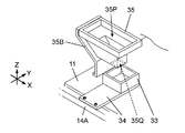
- a component disposal box 33 is installed in each of the equipment installation area on the front side and the equipment installation area on the rear side.
- the component disposal box 33 has a box shape opened upward (see also FIG. 4).
- the component BH is replaced with the board KB.
- Discarded components are put into the front-side component disposal box 33 from the front-side mounting head 17, and discarded components are put into the rear-side component disposal box 33 from the rear-side mounting head 17.
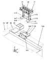
- a carrier holding member 14 ⁇ / b> A is provided at an end on the base side of the feeder truck 14 so as to extend in the X-axis direction.
- the base of a box holding member 34 which is a carrier of the component disposal box 33 is attached to the carrier holding member 14A.
- the box holding member 34 extends toward the center of the base 11, and detachably holds the box holding member 34 at its tip.
- the box holding member 34 is located at a position protruding toward the base 11 from the feeder base 14F, in other words, at a position protruding toward the transport conveyor 13 as a substrate positioning unit with respect to the feeder base 14F.
- the tip end of the box holding member 34 is located in the equipment installation area of the base 11 in a state where it is connected to the feeder trolley 14, so that the feeder trolley 14 is connected to the base 11.
- the component disposal box 33 is located in the equipment installation area of the base 11 (that is, in the movable area of the mounting head 17) (FIG. 4).
- a shooter 35 is provided in each of the equipment installation area on the front side of the base 11 and the equipment installation area on the rear side of the base 11. As shown in FIG. 6, the shooter 35 is formed in a cylindrical shape as a whole, and has an input port 35P opened upward and a discharge port 35Q opened downward.
- the chute 35 is attached to the base 11 via a chute bracket 35B attached to the base 11, and the chute 35 is relatively fixed to the base 11.
- the opening area of the inlet 35P is larger than the opening area of the outlet 35Q.
- the mounting head 17 puts the discarded component into the slot 35P of the shooter 35.
- the discarded component put into the input port 35P of the shooter 35 is discharged from the discharge port 35Q and stored (discarded) in the component disposal box 33.
- a mounting table 36 which is a carrier of the nozzle exchange table 31, is attached to a carrier holding member 14A provided on the feeder cart 14 via a bracket 14B in addition to the box holding member 34 described above.
- the mounting table 36 has a shape spread in the XY plane, and the nozzle exchange table 31 before being held by the exchange table holding unit 32 is mounted (temporarily placed).
- the upper surface of the mounting table 36 is provided with a fitting hole 36 ⁇ / b> K having a shape depressed downward.
- the mounting table 36 is, similarly to the box holding member 34 described above, at a position protruding from the feeder base 14F toward the base 11 side, in other words, at a position protruding from the feeder base 14F toward the transport conveyor 13 as a substrate positioning unit. positioned.
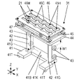
- FIGS. 10A and 10B show the nozzle changing table 31.
- the nozzle exchange table 31 includes a pedestal 41, two columns 42, four rollers 43, a base 44, a nozzle support 45, and a shutter 46.
- a positioning projection 41K protruding downward is provided (see also FIG. 9).
- the positioning projection 41K has a shape that can be fitted into the fitting hole 36K provided on the upper surface of the mounting table 36 from above.
- two guide projections 41T projecting downward are provided at both ends of the pedestal 41 in the X-axis direction (see also FIG. 9).
- the distance between the two guide protrusions 41T is slightly larger than the length of the mounting table 36 in the X-axis direction.
- the length of the half of the pedestal 41 on the base side (referred to as the pedestal inner part 41B) in the X-axis direction is smaller than the length of the half of the pedestal 41 on the near side in the X-axis direction.
- Both side surfaces in the X-axis direction of the pedestal back portion 41B are guided surfaces 41G parallel to the YZ plane.
- the two columns 42 are provided at both ends in the X-axis direction of the upper surface of the pedestal 41 so as to face each other in the X-axis direction, and extend in the Z-axis direction.
- the four rollers 43 are provided on the outer side surface of each of the two columns 42, two by two in the Z-axis direction.
- the base portion 44 has a shape spread in the XY plane, and the lower surface is supported by the two columns 42.
- the nozzle support 45 is formed of a block-shaped member and is provided on the upper surface side of the base portion 44.
- the nozzle support 45 is provided with a plurality of nozzle insertion holes 45H opened on the upper surface in a matrix (see also FIGS. 11A and 11B).
- the inner diameter of each nozzle insertion hole 45H is slightly larger than the outer diameter of the tube portion 23 of the nozzle 21.
- the shutter 46 is formed of a rectangular flat plate-shaped member that spreads in the XY plane.
- the shutter 46 is located above the nozzle support 45 and is slidable in the X-axis direction with respect to the nozzle support 45.
- the shutter 46 has a plurality of circular holes 46C provided in the same arrangement as the plurality of nozzle insertion holes 45H provided in the nozzle support 45 (see also FIGS. 11A and 11B).
- each circular hole 46C provided in the shutter 46 is larger than the inner diameter of the nozzle insertion hole 45H of the nozzle support 45 and larger than the outer diameter of the flange 24 of the nozzle 21.
- the plurality of circular holes 46C arranged in the X-axis direction are penetrated by grooves 46M extending in the X-axis direction (see also FIGS. 11A and 11B).
- the width (dimension in the Y-axis direction) of each groove 46M is smaller than the outer diameter of the flange 24 of the nozzle 21 and larger than the outer diameter of the base 22 of the nozzle 21.
- FIGS. 10A and 10B and FIGS. 11A and 11B below the shutter 46, a frame-shaped member 47 that is connected to the shutter 46 and moves in the X-axis direction integrally with the shutter 46 is provided below the shutter 46.
- An operated piece 48 protruding and extending toward the center of the base 11 is provided at an end of the frame 47 at the center of the base 11 (FIGS. 10B and 11A and 11B).
- 11A and 11B, between the frame-shaped member 47 and the nozzle support 45 an urging member 49 composed of, for example, a tension spring is provided. The urging member 49 urges the frame-shaped member 47 (that is, the shutter 46) against the nozzle support 45 in the X-axis direction.
- the shutter 46 When the operating force for operating the operated piece 48 in the X-axis direction is removed from the state where the shutter 46 is located at the open position, the shutter 46 is urged by the urging member 49 and returns to the closed position (FIG. 11B ⁇ FIG. 11A). .
- the nozzle 21 in which the tube portion 23 is inserted into the nozzle insertion hole 45 ⁇ / b> H cannot be pulled out upward because the flange portion 24 interferes with the lower surface of the shutter 46. Therefore, the nozzle 21 inserted into the nozzle insertion hole 45H does not fall off from the nozzle replacement table 31 when the shutter 46 is in the closed position.
- FIG. 12 shows the exchange table holder 32.
- the exchange table holding unit 32 includes a base plate 51, two support plates 52, two roller guides 53, an elevating cylinder 54, an elevating plate 55, a shutter operating cylinder 56, and a shutter operating unit 57 as a movable unit operating unit.
- the base plate 51 is composed of a plate-shaped member.
- the two support plates 52 are provided at both ends of the base 11 in the X-axis direction so as to face each other in the X-axis direction, and each extend in the Z-axis direction.
- the two roller guides 53 are provided on inner surfaces of the two support plates 52 (surfaces on the side where the support plates 52 oppose each other in the X-axis direction).
- each of the two roller guides 53 has a front wall 61 and a rear wall 62 located on the center side of the base 11 of the front wall 61.
- the space between the front wall 61 and the rear wall 62 is a guide groove 63 extending in the Z-axis direction.
- the guide groove 63 has a width W2 (FIGS. 12 and 13) slightly larger than the outer diameter W1 of the roller 43 (FIG. 10A).
- a groove 61M penetrating in the Y-axis direction is provided in the front wall 61 so as to extend in the Z-axis direction (FIG. 13).
- the vertical width W3 (FIGS. 12 and 13) of the groove 61M is larger than the outer diameter W1 of the roller 43.
- the lifting cylinder 54 as lifting means for lifting and lowering the nozzle exchange table 31 is provided with the lifting rod 54R as a piston rod directed downward.
- the elevating plate 55 is a member that supports the pedestal 41 of the nozzle exchange table 31 from below, and is connected to the lower end of the elevating rod 54R. The elevating plate 55 moves (elevates) in the Z-axis direction when the elevating cylinder 54 operates the elevating rod 54R.
- two guide rollers 55R extending in the Z-axis direction and rotatable around the Z-axis are provided side by side in the Y-axis direction at both ends in the X-axis direction of the upper surface of the elevating plate 55, respectively.
- a holding member 55P extends in the Y-axis direction above the two left and right guide rollers 55R (two guide rollers 55R arranged in the Y-axis direction) among the four guide rollers 55R.
- the distance between the two guide rollers 55R facing each other in the X-axis direction is slightly larger than the width in the X-axis direction of the pedestal back portion 41B of the nozzle replacement table 31.
- the distance between the upper surface of the base plate 51 and the lower surface of each pressing member 55P is slightly larger than the thickness-direction dimension of the pedestal back portion 41B of the nozzle replacement table 31.
- the shutter operation cylinder 56 is provided at a position closer to the center of the base 11 than the elevating cylinder 54 with the shutter operation rod 56R, which is a piston rod, oriented in the X-axis direction.
- the shutter operating section 57 extends in the Z-axis direction, and the lower end thereof is connected to the distal end of the shutter operating rod 56R.
- the shutter operation section 57 moves in the X-axis direction while maintaining the posture extended in the Z-axis direction.
- the carrier holding member 14A of the feeder cart 14 is used.
- the nozzle replacement table 31 is mounted on the mounting table 36 attached to the nozzle.
- the pedestal 41 of the nozzle replacement table 31 is mounted on the upper surface of the mounting table 36 (FIG. 9 ⁇ FIG. 14).
- the positioning protrusion 41K on the lower surface of the pedestal 41 is fitted into the fitting hole 36K of the mounting table 36 from above, and the mounting table 36 is positioned between the two guide protrusions 41T.
- the nozzle replacement table 31 is positioned at a specified position with respect to the mounting table 36 (FIG. 14).
- the operator OP moves the feeder truck 14 on the floor surface and transports it to the base 11, and connects the truck-side connector 14C of the feeder truck 14 to the base-side connector 11C.
- the cart lock unit 11R controlled by the control device 20 locks the feeder cart 14 to the base 11, and connects the feeder cart 14 to the base 11.
- the nozzle replacement table 31 mounted on the mounting table 36 is replaced in the area between the parts feeder 15 attached to the feeder trolley 14 and the replacement table holder 32. It is delivered to the table holder 32.
- the pedestal deep portion 41 ⁇ / b> B of the nozzle exchange table 31 mounted on the mounting table 36 is located in the space between the lifting plate 55 of the exchange table holder 32 and the pressing member 55 ⁇ / b> P. It enters (FIG. 15 ⁇ FIG. 16 ⁇ FIG. 17).
- the exchange table holder 32 receives the nozzle exchange table 31 from the mounting table 36.
- the pedestal back part 41B of the nozzle replacement pedestal 31 enters between the lifting plate 55 of the replacement pedestal holding part 32 and the pressing member, the two guided surfaces 41G at both ends of the pedestal back part 41B of the nozzle replacement pedestal 31 are replaced. It is guided from the side (X-axis direction) by four (two right and left) guide rollers 55 ⁇ / b> R provided in the table holder 32.
- the left and right upper and lower rollers 43 become two roller guides provided on the exchanging table holding unit 32. It enters the guide groove 63 of 53 (FIG. 16 ⁇ FIG. 17, see arrows M1 and M2 shown in FIG. 16).
- the upper roller 43 of the upper and lower rollers 43 enters the guide groove 63 through the groove 61M provided in the front wall 61 (arrow M1), and the lower roller 43 is the lower front wall. It enters the guide groove 63 from below 61 (arrow M2).
- the right and left upper and lower rollers 43 complete the entry of the left and right roller guides 53 into the guide grooves 63 when the feeder cart 14 is connected to the base 11.
- the lifting cylinder 54 raises the lifting plate 55.
- the nozzle exchange table 31 is lifted by the elevating cylinder 54 via the elevating plate 55 (FIGS. 17 to 18), and the pedestal 41 of the nozzle exchange table 31 is separated from the elevating plate 55 of the exchange table holder 32 (accordingly, , Mechanically separated from the feeder cart 14) and moves upward.
- the lifting cylinder 54 stops lifting the lifting plate 55.
- the four rollers 43 of the nozzle exchange table 31 (the left and right upper and lower rollers 43) are guided by the guide grooves 63 of the left and right roller guides 53, and are in the guide grooves 63. Moves straight (up) vertically upward. Then, when the nozzle replacement table 31 is located at the holding position, the left and right upper and lower rollers 43 are sandwiched by the front wall 61 and the rear wall 62, respectively. Therefore, the nozzle exchange table 31 is firmly held at a predetermined holding position by the exchange table holding unit 32 (FIGS. 18 and 19).
- the component mounting apparatus 1 is provided on the base 11 and the nozzle replacement table 31 that holds the replacement nozzle 21 that is attached to and detached from the mounting head 17.
- the exchange table holder 32 receives the nozzle exchange table 31 from the mounting table 36, raises the same, and holds the nozzle exchange table 31 in a state where the nozzle exchange table 31 is separated from the mounting table 36. It is designed to be held in position.
- the exchange table holding section 32 serves as an exchange table moving means for elevating and lowering the nozzle exchange table 31 received from the mounting table 36 such that the elevation cylinder 54 and the nozzle exchange table 31 which is moved up and down by the elevation cylinder 54 rise toward the holding position.
- a left and right roller guide 53 as a guide member for guiding the rollers.
- the nozzle exchange table 31 is moved obliquely upward toward the center of the base 11 with respect to the exchange table holding unit 32 (see FIG. 16 ⁇ FIG. 17).
- the operated piece 48 is located on the side of the shutter operating section 57 provided in the exchange table holding section 32 (FIGS. 16 ⁇ 17 and 20A ⁇ 20B).
- the nozzle exchange table 31 is moved upward by the lifting cylinder 54.
- the operated piece 48 is located on the side of the shutter operation section 57.
- the state is maintained (FIG. 17 ⁇ FIG. 18).
- the operated piece 48 is located on the side of the shutter operating unit 57.
- the shutter 46 can be switched from the closed position to the open position (FIG. 21A ⁇ FIG. 21B).
- the shutter operation section 57 is returned to the original position by the shutter operation cylinder 56 after switching the shutter 46 to the open position, the shutter 46 returns to the closed position by the urging force of the urging member 49 (see FIG. 21B ⁇ FIG. 21B). 21A).
- the shutter operation unit 57 as the movable unit operation unit that operates the shutter 46 that is the movable unit of the nozzle exchange table 31 and the shutter operation cylinder 56 as the actuator that drives the shutter operation unit 57 are formed. It is provided in the exchange stand holder 32. Then, in a state where the nozzle exchange table 31 is held at the holding position by the exchange table holding unit 32, the shutter operation unit 57 is located at a position where the shutter 46 of the nozzle exchange table 31 can be operated.
- the mounting table 36 is provided with a mounting state detection sensor 71.
- the placement state detection sensor 71 detects a state where the nozzle replacement table 31 is placed on the placement table 36, and outputs a detection signal to the control device 20.
- the control device 20 detects a state in which the nozzle replacement table 31 is mounted on the mounting table 36 based on an output of the mounting state detection sensor 71.
- a holding state detection sensor 72 is provided in the exchange table holding unit 32.
- the holding state detection sensor 72 detects a state in which the nozzle replacement table 31 is held at the holding position based on the amount of downward projection of the piston rod (elevation rod 54R) of the elevating cylinder 54 and the magnitude of the load.
- the detection signal is output to the control device 20.
- the control device 20 detects a state in which the nozzle replacement table 31 is held at the holding position based on the output of the holding state detection sensor 72.
- the component disposal box 33 attached to the feeder trolley 14 enters the equipment installation area of the base 11, and moves below the discharge port 35 ⁇ / b> Q of the shooter 35. (FIG. 22A ⁇ FIG. 22B). Therefore, the worker OP can install the parts disposal box 33 within the movable range of the mounting head 17 by connecting the feeder truck 14 to the base 11 without opening the door portion 12C of the base cover 12. it can.
- the replacement work of the nozzle 21 is performed in a state where the nozzle replacement table 31 is held at the holding position by the replacement table holding unit 32.
- the replacement work of the nozzle 21 is performed by holding the nozzle 21 attached to the nozzle shaft 17S on the nozzle replacement base 31 and removing it from the nozzle shaft 17S, and then replacing the replacement nozzle 21 held on the nozzle replacement base 31 with the nozzle. This is performed by attaching to the shaft 17S.
- the exchange operation for the plurality of nozzles 21 is collectively executed.
- the shutter operation cylinder 56 operates to move the shutter 46 from the closed position to the open position (FIG. 21A ⁇ FIG. 21B). Then, the mounting head 17 moves, and the vertical center axis of the nozzle 21 is aligned with the vertical center axis of the nozzle insertion hole 45H of the nozzle replacement table 31. When the vertical center axis of the nozzle 21 coincides with the vertical center axis of the nozzle insertion hole 45H, the mounting head 17 lowers the nozzle shaft 17S, and moves the nozzle 21 attached to the nozzle shaft 17S to the vacant nozzle insertion hole 45H. Insert.
- the shutter operation cylinder 56 operates to move the shutter 46 from the open position to the closed position (FIG. 21B ⁇ FIG. 21A).
- the flange portion 24 of the nozzle 21 interferes with the shutter 46 and is prevented from moving upward.
- the nozzle 21 is removed from the nozzle 17S and remains on the nozzle changing table 31. As a result, the nozzle 21 is removed from the nozzle shaft 17S.
- the replacement nozzle 21 is attached to the nozzle shaft 17S from which the nozzle 21 has been removed in this way, first, the mounting head 17 moves and the replacement nozzle 21 held on the nozzle replacement table 31 is moved. The nozzle shaft 17S to which the nozzle 21 is attached is located above. Then, the vertical center axis of the nozzle shaft 17S is made to coincide with the vertical center axis of the nozzle 21, and the nozzle shaft 17S is lowered. As a result, the base 22 of the replacement nozzle 21 is connected (fitted) to the lower end of the nozzle shaft 17S.
- the shutter operation cylinder 56 operates to move the shutter 46 from the closed position to the open position (FIG. 21A ⁇ FIG. 21B).
- the mounting head 17 pulls the nozzle shaft 17S upward.
- the nozzle 21 is pulled up in a state where the nozzle 21 is connected to the lower end of the nozzle shaft 17S, and the nozzle 21 for replacement is attached to the nozzle shaft 17S.
- the replacement work of the nozzle 21 is completed.
- the lifting cylinder 54 lowers the lifting plate 55.
- the nozzle exchange table 31 lifted by the lifting plate 55 moves on a path reverse to that when it is held at the holding position, and is mounted on the mounting table 36 provided on the feeder cart 14.
- the four rollers 43 of the nozzle exchange table 31 move straight down vertically through the guide grooves 63 of the two roller guides 53 included in the exchange table holder 32 (FIG. 18 ⁇ FIG. 17).
- the nozzle exchange table 31 After the nozzle exchange table 31 is mounted on the mounting table 36 as described above, when the feeder cart 14 is separated from the base 11, the nozzle exchange table 31 remains in the state of being mounted on the mounting table 36. It moves obliquely downward toward the direction away from the center of the table 11 and separates from the elevating plate 55 (FIG. 17 ⁇ FIG. 16). After that, it moves together with the feeder truck 14 while being placed on the placing table 36, and separates from the base 11 (FIG. 16 ⁇ FIG. 15). As described above, the exchange table holding unit 32 lowers the nozzle exchange table 31 from the holding position and mounts the nozzle exchange table 31 on the mounting table 36.
- Such a replacement operation of the nozzle replacement table 31 and the component disposal box 33 is performed in a state where the component mounting operation on the side where the nozzle replacement table 31 and the component disposal box 33 to be replaced is installed is stopped.
- the operator OP With the door 12C opened, the operator OP can insert the hand into the work space 11S to perform the operation.
- the safety device operates by opening the door portion 12C, while performing the replacement work of the nozzle replacement table 31 or the replacement work of the parts disposal box 33, the parts on the opposite side to the work side are performed.
- the mounting operation is also forcibly stopped.
- the nozzle replacement table 31 and the parts disposal box 33 are moved within the installation area of the base 11 (that is, the movable range of the mounting head 17). (Inner), and by separating the feeder cart 14 from the base 11, the nozzle replacement table 31 and the parts disposal box 33 can be separated from the equipment installation area of the base 11. Therefore, the replacement of the nozzle replacement table 31 can be performed by replacing the parts disposal box 33 without opening the door 12C.
- the operator OP does not need to open the door portion 12C of the base cover 12, so that the safety device does not operate, and the nozzle replacement table 31 and the parts disposal box 33 are replaced on one of the front side and the rear side. Is performed, the component mounting operation is continued on the other side, so that the operation of the component mounting apparatus 1 as a whole is maintained.
- the replacement of the nozzle replacement table 31 and the replacement of the component disposal box 33 (that is, the recovery of the waste component) can be easily performed without opening the door 12C of the base cover 12. Can be done. Further, since the door portion 12C cannot be opened, the safety device does not work and the component mounting operation is not forcibly stopped, and the replacement work of the nozzle replacement table 31 and the replacement work of the component disposal box 33 can be performed efficiently. . Next, the flow of operation of each part of the component mounting apparatus 1 in the replacement work of the nozzle replacement table 31 by the feeder truck 14 will be described.
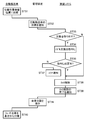
- FIG. 23 shows an operation flow of the component mounting apparatus 1 in a case where the feeder truck 14 connected to the base 11 is separated from the base 11 in the replacement work of the nozzle replacement table 31.
- the operator OP first performs an input operation for requesting permission (separation permission) to separate the feeder truck 14 from the touch panel TP. (Step ST1 in the flowchart of FIG. 23).
- the operation of requesting the separation permission is performed from the touch panel TP on the side where the worker OP is going to separate the feeder cart 14.
- control unit 20 When the control device 20 detects that the operation for requesting the separation has been performed from the touch panel TP, the control unit 20 separates the feeder carriage 14 from the base 11 when the nozzle replacement platform held by the replacement platform holding unit 32. 31 is also notified to the operator OP to confirm whether to remove it together (step ST2). This notification is performed by displaying a message inquiring on the screen of the touch panel TP as to whether or not the nozzle exchange table 31 is to be removed. Then, when the operator OP inputs a response to the notification on the touch panel TP (step ST3), the control device 20 checks the contents of the response input by the operator OP in step ST3 (step ST4).
- the control device 20 operates the elevating cylinder 54 of the exchange table holding unit 32 to lower the nozzle exchange table 31 and place it on the mounting table 36. Thereby, the nozzle exchange table 31 is detached from the exchange table holder 32 (step ST5).
- the control device 20 determines whether or not the nozzle exchange table 31 has been normally removed based on the output from the placement state detection sensor 71 ( Step ST6). Specifically, when it is detected that the nozzle replacement table 31 is mounted on the mounting table 36 within a predetermined time after the operation of the elevating cylinder 54 is started, the nozzle replacement table 31 is normally removed. Judge that it was done. On the other hand, if it is not detected that the nozzle replacement table 31 has been mounted on the mounting table 36 even after the predetermined time has elapsed, it is determined that the nozzle replacement table 31 has not been properly removed. .
- control device 20 determines that the removal of the nozzle replacement table 31 has been performed normally, the control device 20 causes the bogie lock unit 11R to perform an operation of unlocking the feeder bogie 14 (step ST7). On the other hand, if it is determined that the removal of the nozzle replacement table 31 has not been performed normally, the control device 20 operates through the touch panel TP without causing the carriage lock unit 11R to perform the operation of unlocking the feeder carriage 14. The user OP is notified of an error (step ST8). If the controller 20 confirms in step ST4 that the answer input by the operator OP does not remove the nozzle exchange table 31, the control apparatus 20 removes the nozzle exchange table 31 from the exchange table holding unit 32. Instead, the truck lock unit 11R releases the lock of the feeder truck 14 (step ST7).
- the control device 20 When the unlocking of the feeder trolley 14 by the trolley lock unit 11R is completed, the control device 20 notifies the operator OP through the touch panel TP that the unlocking of the feeder trolley 14 is completed (step ST9). Upon receiving the notification that the lock of the feeder cart 14 has been released via the touch panel TP, the operator OP operates the feeder cart 14 to separate it from the base 11 (step ST10). Thus, the operation of separating the feeder cart 14 from the base 11 is completed.
- the control device 20 controls the exchange platform.
- An inquiry is made to the operator OP as to whether or not the nozzle exchange table 31 held by the holding section 32 is to be removed from the exchange table holding section 32. If the answer from the operator OP is to remove the nozzle exchange table 31, the nozzle exchange table 31 is detached from the exchange table holding unit 32 and is placed on the mounting table 36, and then the feeder cart 14 is inserted into the cart lock unit 11R.
- the feeder carriage 14 can be inserted into the carriage lock unit 11R without causing the exchange table holder 32 to remove the nozzle exchange table 31. The lock is released.
- the nozzle exchange table 31 held by the exchange table holding section 32 can be removed together, so that the door section 12C of the base cover 12 is not opened. Also, the replacement work of the nozzle replacement table 31 can be easily performed. As described above, when the component mounting operation of the component mounting apparatus 1 is not performed at all, as described above, the operator OP opens the door portion 12C, inserts the hand into the work space 11S, and manually replaces the door. It is also possible to perform the replacement work of the nozzle replacement table 31 with respect to the table holding unit 32.
- the nozzle exchange table 31 located at the holding position may be pulled upward as it is, and when attaching the nozzle exchange table 31, What is necessary is just to follow the procedure reverse to removal.
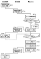
- FIG. 24 shows an operation flow of the component mounting apparatus 1 in a case where the nozzle replacement table 31 is installed on the base 11 by connecting the feeder truck 14 to the base 11 in the replacement work of the nozzle replacement table 31. ing.
- the operator OP When installing the nozzle replacement table 31 on the base 11 by connecting the feeder cart 14 to the base 11, the operator OP first places the nozzle replacement table 31 on the mounting table 36 (FIG. Step ST11 of the flowchart of FIG. 24). Then, an input operation for requesting permission (connection permission) to connect the feeder cart 14 to the base 11 is performed from the touch panel TP (step ST12). This connection permission request operation is performed from the touch panel TP on the side where the operator OP tries to connect the feeder truck 14.
- a request for connection permission is performed from the front touch panel TP, and the feeder truck 14 is connected to the rear side of the base 11.
- a connection permission request operation is performed from the rear touch panel TP.
- the exchange platform on the side where the feeder cart 14 is to be connected to the worker OP through the touch panel TP detects that a connection permission request operation has been performed from the front or rear touch panel TP
- the exchange platform on the side where the feeder cart 14 is to be connected to the worker OP through the touch panel TP A request is made to confirm whether the holding unit 32 is empty (step ST13). This request is made by displaying a message that calls attention to the operator OP on the screen of the touch panel TP.
- the operator OP performs an erroneous operation of connecting the feeder cart 14 with the nozzle exchange table 31 in a state where the nozzle exchange table 31 that has not been removed is mounted on the exchange table holding unit 32. There is no.
- step ST14 After the operator OP confirms the state where the nozzle exchange table 31 is not placed on the exchange table holding unit 32 by visual observation or the like, and gives a reply to that effect from the touch panel TP (step ST14), the control device 20 Then, the operator OP is urged to connect the feeder truck 14 to the base 11 through the touch panel TP (step ST15).
- step ST16 When prompted to connect the feeder cart 14 to the base 11, the worker OP pushes the feeder cart 14 into the base 11 (step ST16). After prompting the worker OP to connect the feeder trolley 14 to the base 11 in step ST15, the control device 20 determines the position where the feeder trolley 14 can be connected to the base 11 based on the output of the trolley detection sensor 11M. Is reached (step ST17). When detecting that the feeder truck 14 has reached a position where the feeder truck 14 can be connected, the control device 20 locks the feeder truck 14 with the truck lock unit 11R and connects the feeder truck 14 to the base 11 (step ST18). The elevating cylinder 54 of the exchange table holder 32 is operated to hold the nozzle exchange table 31 by the exchange table holder 32 (step ST19). Thus, the installation of the nozzle replacement table 31 on the base 11 is completed.
- FIG. 25 is a flowchart showing the modification.
- the operator OP performs an input operation requesting permission (separation permission) for separating the feeder cart 14 from the touch panel TP (step ST21).
- the operation of requesting the separation permission is performed from the touch panel TP on the side where the worker OP is going to separate the feeder cart 14.
- the control device 20 detects that the operation of requesting the separation is performed from the touch panel TP, the control device 20 refers to the setup change information stored in the storage unit of the control device 20 or a server device that can communicate with the control device 20. (Step ST22).
- This setup change information is created in advance based on the production plan. Then, if it is confirmed by the setup change information that the nozzle exchange table 31 is to be removed together with the feeder cart 14 for which separation permission has been requested (step ST23), the control device 20 operates the elevating cylinder 54 of the exchange table holder 32. Then, the nozzle replacement table 31 is lowered and mounted on the mounting table 36, thereby removing the nozzle replacement table 31 from the replacement table holder 32 (step ST24). Then, when it is confirmed that the removal of the nozzle replacement table 31 has been performed normally (step ST25), the carriage lock unit 11R releases the lock (step ST26).
- control device 20 When the control device 20 confirms that the nozzle replacement table 31 is not removed (step ST23), the control unit 20 skips steps ST24 and ST25 and causes the bogie lock unit 11R to release the lock (step ST26). If it is determined that the nozzle replacement table 31 has not been properly removed, the control device 20 controls the operator OP through the touch panel TP without causing the carriage lock unit 11R to perform the operation of unlocking the feeder carriage 14. (Step ST27).
- the control device 20 When the unlocking of the feeder trolley 14 by the trolley lock unit 11R is completed, the control device 20 notifies the worker OP of the completion of the unlocking of the feeder trolley 14 through the touch panel TP (step ST28). Upon receiving the notification that the lock of the feeder cart 14 has been released through the touch panel TP, the operator OP operates the feeder cart 14 to separate it from the base 11 (step ST29). As described above, in the modified example, the component mounting apparatus 1 determines whether to remove the nozzle replacement table 31 based on the information (setup change information) based on the production plan. it can.
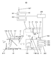
- FIG. 26 shows a combination of a mounting system including the component mounting apparatus 1, a self-propelled automatic transport vehicle 81, and an automatic transport system having a management device 82 for guiding the automatic transport vehicle 81 to travel on the floor.
- 3 shows a configuration example of a work system 83.
- the automatic transport vehicle 81 is equipped with a wireless communication device 81T, and the management device 82 wirelessly transmits and receives signals to and from the automatic transport vehicle 81 via the wireless communication device 81T by the wireless communication device 82T.
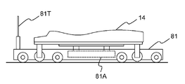
- the automatic transport vehicle 81 includes a capturing mechanism 81A (see FIG. 29) that lifts and captures the feeder truck 14.
- the automatic transport vehicle 81 travels while being guided wirelessly by the management device 82, enters under the feeder vehicle 14, and then captures the feeder vehicle 14 by the capturing mechanism 81A and transports the vehicle in a state of being lifted off the floor (FIG. 30). reference).
- the management device 82 can move the automatic transport vehicle 81 and transport the feeder vehicle 14, thereby connecting or separating the feeder vehicle 14 from the base 11.
- the capturing mechanism 81A is not limited to the one that lifts the feeder truck 14, and may be one that engages with the feeder truck 14 in a towable state.
- the mounting system includes at least the component mounting apparatus 1 and an information management unit 205 connected to the control device 200 of the component mounting apparatus 1.
- the information management unit 205 functions as a higher-level control unit of the component mounting apparatus 1, downloads data, programs, and the like necessary for operation of the component mounting apparatus 1 to the component mounting apparatus 1, and outputs information indicating the state of the component mounting apparatus 1. Receive log information and the like.
- the management device 82, the information management unit 205, and the control device 200 are connected via a wired or wireless communication network, and the automatic transport system and the mounting system transport the feeder cart 14 while communicating over the communication network.
- the management device 82 includes a first notification unit 821 that notifies the mounting system of an arrival notification that the automatic transport vehicle 81 has arrived at a position where the feeder vehicle 14 can be transported, and the feeder vehicle 14 by the vehicle lock unit 11R from the mounting system.
- the control device 200 has a function of controlling the component mounting device 1 and has a second notification unit 202 and a second processing unit 203.
- the second processing unit 203 receives the arrival notification from the automatic transport system, the second processing unit 203 transfers the nozzle exchange table 31 from the exchange table holding unit 32 to the mounting table 36, and releases the lock of the feeder cart 14 to the cart lock unit 11R. To perform a release operation.
- the second notification unit 202 notifies the automatic transport system of a release notification when the release operation by the bogie lock unit 11R is normally performed.
- the control device 200 further includes a determination unit 204 for determining whether to remove the nozzle exchange table 31 held by the exchange table holding unit 32.
- the determination unit 204 refers to the setup change information stored in the control device 200 or the information management unit 205 to determine whether to remove the nozzle replacement table 31. This setup change information is created in advance based on the production plan.
- FIG. 27 shows a flow of operation when the feeder truck 14 connected to the base 11 is separated from the base 11 by the automatic carrier 81.
- the automatic carrier 81 is brought to a position near the component mounting apparatus 1 by the management device 82, and further, The user is moved to a position (separation work standby position) where separation work for separating a predetermined feeder cart 14 mounted on the component mounting apparatus 1 can be started.
- the separation work standby position is below the feeder cart 14. Then, when the automatic transport vehicle 81 arrives at the separation work standby position (step ST31 in FIG.
- the first notification unit 821 instructs the control device 20 of the component mounting device 1 to send the automatic transport vehicle 81 the component mounting device 1 (Step ST32).
- This arrival notification is sent via the information management unit 205 to the control device 20 of the component mounting apparatus 1 on which the feeder cart 14 to be removed is mounted.
- the determination unit 204 determines whether to remove the nozzle replacement table 31 with reference to the setup change information (step ST33).
- the second processing unit 203 causes the replacement table holding unit 32 to remove the nozzle replacement table 31 (step ST34). Then, based on the output from the placement state detection sensor 71, it is determined whether or not the removal of the nozzle replacement table 31 by the replacement table holding unit 32 has been performed normally (step ST35).
- the second processing unit 203 starts the separation operation, and causes the carriage lock unit 11R to unlock the feeder carriage 14 (step ST36). .
- step ST35 determines in step ST35 that the removal of the nozzle replacement table 31 has not been performed normally
- the second processing unit 203 does not allow the bogie lock unit 11R to unlock the feeder bogie 14 without touching the touch panel.
- An error notification is sent to the worker OP through the TP (step ST37).
- the determination unit 204 determines in step ST23 that the nozzle replacement table 31 is not to be removed
- the second processing unit 203 starts the separation operation without causing the replacement table holding unit 32 to remove the nozzle replacement table 31.
- the trolley lock unit 11R releases the lock of the feeder trolley 14 (step ST36).
- the second notification unit 202 notifies the automatic transport system of the completion of the lock release through the information management unit 205 (hereinafter, referred to as lock release notification). (Step ST38). Then, upon receiving the lock release notification, the first notification unit 821 of the management device 82 instructs the automatic transport vehicle 81 to separate the feeder truck 14 (dolly separation) (step ST39).
- the automatic transport vehicle 81 that has received the instruction to separate the carts catches the feeder carts 14 by lifting them off the floor or the like, and moves away from the component mounting apparatus 1 in a state where the feeder carts 14 are lifted off the floor.
- the vehicle travels (step ST40). Thereby, the separating operation for separating the feeder cart 14 from the base 11 is completed.
- the management device 82 controls the control device before the automatic transport vehicle 81 transports the feeder vehicle 14 and separates the feeder vehicle 14 from the base 11.
- Reference numeral 200 determines whether or not the nozzle exchange table 31 held by the exchange table holder 32 is to be removed from the exchange table holder 32.
- the nozzle exchange table 31 is detached from the exchange table holder 32 and is mounted on the mounting table 36, and then the carriage lock unit 11R releases the lock of the feeder cart 14 to replace the nozzle.
- the carriage lock part 11R releases the lock of the feeder carriage 14 without causing the replacement base holding part 32 to remove the nozzle replacement base 31.
- FIG. 28 shows an operation flow when the feeder truck 14 is connected to the base 11 by the automatic transport vehicle 81 and the nozzle replacement table 31 is installed on the base 11.
- the automatic transporter 81 moves the feeder trolley 14 to be connected to the component mounting apparatus 1 to a connection work standby position near the component mounting apparatus 1.
- the first notification unit 821 that has detected the automatic transport vehicle 81 informs the information management unit 205 of the mounting system that the automatic transport vehicle 81 has the feeder truck.
- an arrival notification is sent to the user, indicating that the server 14 has been transported to the connection work standby position where the connection work can be started (step ST42).
- the automatic transport vehicle 81 waits with the mounting table 36 of the feeder truck 14 facing the component mounting apparatus 1.
- the information management unit 205 relays the arrival notification from the first notification unit 821 to the control device 200 of the component mounting apparatus 1.
- the second processing unit 203 of the control device 200 checks whether or not the nozzle exchange table 31 remains in the exchange table holder 32 on the side to which the feeder truck 14 is connected (step ST43). More specifically, this confirmation is performed based on the output of the above-mentioned holding state detection sensor 72 by determining whether or not the replacement table holder 32 is holding the nozzle replacement table 31.
- the second processing unit 203 determines whether or not the nozzle exchange table 31 can be attached to the exchange table holder 32 based on whether or not the nozzle exchange table 31 is held in the exchange table holder 32 (step). ST44).
- the second processing unit 203 transmits the information through the information management unit 205.
- the automatic transport system is notified of connection permission (step ST45), and enters a standby state to wait for the feeder truck 14 transported by the automatic transport vehicle 81 to be detected by the truck detection sensor 11M (step ST46).
- an error notification is sent to the operator OP through the touch panel TP (step ST47).
- the first processing unit 822 of the management device 82 Upon receiving the connection permission from the mounting system, the first processing unit 822 of the management device 82 sends an operation command to the automatic carrier 81 waiting at the connection work standby position to start the connection work (step ST48). .
- the automatic transport vehicle 81 having received the operation instruction from the first processing unit 822 transports the feeder truck 14 toward the base 11 (step ST49).
- step ST46 When the feeder trolley 14 approaches the base 11 and the trolley-side connector 14C fits into the base-side connector 11C, the trolley detection sensor 11M reacts, whereby the second processing unit 203 connects the feeder trolley 14 to the base 11.
- the arrival at the work standby position is detected (step ST46).
- the second processing unit 203 detects that the feeder trolley 14 has reached the connection work standby position, the second locker 11R locks the feeder trolley 14 to connect to the base 11 (step ST50). Thereby, the connection operation of the feeder cart 14 is completed.
- the second processing unit 203 operates the elevating cylinder 54 of the exchange table holding unit 32, and causes the exchange table holding unit 32 to hold the nozzle exchange table 31 (step ST51).
- step ST51 is skipped.
- the second notification unit 202 notifies the automatic transport system of the completion of connection indicating that the connection work of the feeder cart 14 is completed (step ST ⁇ b> 52).
- the first processing unit 822 that has received the notification of the completion of the connection instructs the automatic transport vehicle 81 to leave (step ST53).
- the automatic transporting vehicle 81 that has received the instruction to separate releases the feeder truck 14 and separates from the feeder truck 14 (step ST54).
- the exchange base holding unit 32 Since the nozzle replacement table 31 is received from the mounting table 36 and operates so as to be held within the movable range of the mounting head 17, the operator OP can easily open the nozzle replacement table 31 without opening the door portion 12C of the base cover 12. Can be installed on the base 11.
- the exchange table holding unit 32 holds the nozzle exchange table 31 in a state of being separated from the mounting table 36, so that the exchange table holding unit 32 holds the nozzle exchange table 31.
- the feeder cart 14 can be removed from the base 11 as it is.
- the exchange table holding unit 32 returns the held nozzle exchange table 31 to the mounting table 36, the feeder cart 14 is separated from the base 11, so that the nozzle exchange table 31 is moved together with the feeder cart 14 to the position of the base 11. It can be retracted to the outside and removed from the base 11. Therefore, according to the component mounting apparatus 1 of the present embodiment, the operator OP can easily remove the nozzle replacement table 31 from the base 11 without opening the door portion 12C of the base cover 12. it can.
- the door 12C of the base cover 12 cannot be opened, so that the safety device does not work and the component mounting operation does not stop, and the operator OP can efficiently operate.
- the replacement work of the nozzle replacement table 31 can be performed. Therefore, according to the component mounting apparatus 1 of the present embodiment, the operator OP can easily and efficiently exchange the nozzle exchanging table 31 without opening a part of the base cover 12 (the door 12C). Can be.
- the parts disposal box 33 attached to the feeder trolley 14 is located within the movable range of the mounting head 17.
- the component disposal box 33 can be easily installed on the base 11 without opening the 12C.
- the component disposal box 33 can be pulled out of the base 11 together with the feeder cart 14 and removed from the base 11, and the component disposal box 33 can be removed by the mounting head 17. Can be collected.
- the operator OP can easily perform the replacement work of the component disposal box 33 (collection of discarded components) without opening the door portion 12C of the base cover 12. Can be.
- the safety device does not work and the component mounting operation is not stopped, and the operator OP can efficiently operate the component.
- the replacement operation of the disposal box 33 can be performed. Therefore, according to the component mounting apparatus 1 of the present embodiment, the operator OP can easily and efficiently replace the component disposal box 33 without opening a part (the door 12C) of the base cover 12 (see FIG. Collection of waste parts).
- the working system includes the mounting system that mounts the component BH on the board KB and the automatic transport system that includes the automatic transport vehicle 81.
- the system By cooperating with the system, an operation of separating the feeder trolley 14 from the base 11 and an operation of connecting the feeder trolley 14 to the base 11 are performed.
- the automatic transporter 81 is connected to the feeder cart 14 connected to the base 11. Is moved to a position where a separation operation for separating from the base 11 can be started (step ST31). Then, from the automatic transport system that controls the automatic transport vehicle 81, an arrival notification that the automatic transport vehicle 81 has arrived at a position where separation work can be started is notified to the mounting system (step ST32). Then, when the mounting system receives the arrival notification, the coupling mechanism releases the connection of the feeder trolley 14 (step ST36), and notifies the automatic transport system of a release notification from the mounting system indicating that the connection of the feeder trolley 14 has been released. (Step ST38). Then, finally, when the automatic transport system receives the release notification, the automatic transport vehicle 81 moves the feeder cart 14 in a direction away from the base 11 (step ST40).
- the feeder to be connected to the base 11 by the automatic carrier 81 is described.
- the carriage 14 is moved to a position where it can be connected by the connection mechanism (step ST41), and in the mounting system, it is determined whether or not the feeder truck 14 is located at a position where the connection by the connection mechanism is possible (trolley detection sensor 11M).
- the connecting mechanism is operated to connect the feeder truck 14 to the base 11 (step ST50).
- the automatic transport vehicle 81 is connected to the base 11.
- the vehicle is caused to run away from the feeder cart 14 (step ST54).
- the automatic transport system receives a connection permission (step ST45) for permitting connection of the feeder truck 14 to the base 11 from the mounting system, the position at which the feeder truck 14 to be connected can be connected by the connection mechanism. (Step ST49).
- the mounting system and the automatic transport system separate the feeder trolley 14 from the base 11, and the feeder trolley 14 is mounted on the base.
- the operation of linking to 11 is performed by the mounting system and the automatic transport system in cooperation.
- the mounting system and the automatic transport system perform their own operations, they notify the other party of the completion of the operations, and proceed with the operations while confirming each other's operations. Therefore, according to the working system and the method of transporting the feeder trolley 14 (the procedure of transporting the feeder trolley 14 shown in the flowcharts of FIGS. 27 and 28) in the present embodiment, the mounting system and the automatic transport system are linked.
- the feeder cart 14 can be replaced, and the work can be smoothly and reliably progressed.
- the feeder cart 14 is connected to a plurality of locations (the front side and the rear side) of the base 11, but this is merely an example, and A configuration that can be attached may be used. Further, the feeder cart 14 may be connected to a plurality of locations on the front side and the rear side.
- the configuration of the nozzle replacement table 31, the configuration of the replacement table holding unit 32, the component disposal box 33, the box holding member 34, and the like are merely examples, and may have a configuration other than the configuration described in the above embodiment. Good.
- the trolley detection sensor 11M is trolley detection means for detecting that the feeder trolley 14 is located at a position connectable to the base 11, but the trolley detection means may be an optical sensor, a magnetic sensor, or an electric sensor. It is also possible to use a device that can be used for the purpose of detection.
- the management device 82 has a configuration including the first notification unit 821 and the first processing unit 822, but all or a part of them is realized by the automatic transport vehicle 81. You may.
- the control device 200 has a configuration including the second notification unit 202, the second processing unit 203, and the determination unit 204, but all or a part of them may be realized by the information management unit 205. Good.
Landscapes
- Engineering & Computer Science (AREA)
- Manufacturing & Machinery (AREA)
- Microelectronics & Electronic Packaging (AREA)
- Structural Engineering (AREA)
- Transportation (AREA)
- Mechanical Engineering (AREA)
- Life Sciences & Earth Sciences (AREA)
- Geology (AREA)
- Civil Engineering (AREA)
- General Engineering & Computer Science (AREA)
- Quality & Reliability (AREA)
- Physics & Mathematics (AREA)
- General Physics & Mathematics (AREA)
- Automation & Control Theory (AREA)
- Operations Research (AREA)
- Supply And Installment Of Electrical Components (AREA)
- Control Of Position, Course, Altitude, Or Attitude Of Moving Bodies (AREA)
Abstract
L'invention concerne un système d'opération pourvu d'un système de montage permettant de monter un composant sur un substrat, et un système de transfert automatique ayant un véhicule de transfert automatique. Le système de transfert automatique comprend : une première unité de notification qui notifie une notification d'arrivée au système de montage indiquant que le véhicule de transfert automatique est arrivé dans une position dans laquelle il est possible de démarrer une opération de séparation permettant de séparer un chariot d'alimentation couplé à une base à partir de la base ; et une première unité de traitement qui, lors de la réception, en provenance du système de montage, d'une notification de libération indiquant que le couplage du chariot d'alimentation a été libéré, amène le véhicule de transfert automatique à se déplacer dans une direction opposée à la base. En outre, le système de montage comprend : une seconde unité de traitement qui, lors de la réception de la notification d'arrivée, amène un mécanisme de couplage à effectuer une opération de libération pour libérer le couplage du chariot d'alimentation ; et une seconde unité de notification qui, lorsque l'opération de libération a été achevée, notifie une notification de libération au système de transfert automatique.
Priority Applications (7)
| Application Number | Priority Date | Filing Date | Title |
|---|---|---|---|
| DE112019003299.2T DE112019003299T5 (de) | 2018-06-29 | 2019-02-06 | Betriebssystem und zuführschlitten-förderverfahren |
| JP2019562432A JP6827191B2 (ja) | 2018-06-29 | 2019-02-06 | 作業システム及びフィーダ台車の搬送方法 |
| CN201980036375.4A CN112219461B (zh) | 2018-06-29 | 2019-02-06 | 作业系统以及馈送器台车的搬运方法 |
| CN202111638388.4A CN114302636B (zh) | 2018-06-29 | 2019-02-06 | 作业系统以及被搬运物的搬运方法和被搬运物的连结方法 |
| US17/009,165 US11950369B2 (en) | 2018-06-29 | 2020-09-01 | Work system and feeder carriage transfer method |
| US18/591,110 US12225666B2 (en) | 2018-06-29 | 2024-02-29 | Work system and feeder carriage transfer method |
| US18/591,145 US12457726B2 (en) | 2018-06-29 | 2024-02-29 | Work system and feeder carriage transfer method |
Applications Claiming Priority (2)
| Application Number | Priority Date | Filing Date | Title |
|---|---|---|---|
| JP2018-124067 | 2018-06-29 | ||
| JP2018124067 | 2018-06-29 |
Related Child Applications (1)
| Application Number | Title | Priority Date | Filing Date |
|---|---|---|---|
| US17/009,165 Continuation US11950369B2 (en) | 2018-06-29 | 2020-09-01 | Work system and feeder carriage transfer method |
Publications (1)
| Publication Number | Publication Date |
|---|---|
| WO2020003581A1 true WO2020003581A1 (fr) | 2020-01-02 |
Family
ID=68984751
Family Applications (1)
| Application Number | Title | Priority Date | Filing Date |
|---|---|---|---|
| PCT/JP2019/004145 Ceased WO2020003581A1 (fr) | 2018-06-29 | 2019-02-06 | Système d'opération et procédé de transfert de chariot d'alimentation |
Country Status (5)
| Country | Link |
|---|---|
| US (3) | US11950369B2 (fr) |
| JP (2) | JP6827191B2 (fr) |
| CN (2) | CN114302636B (fr) |
| DE (1) | DE112019003299T5 (fr) |
| WO (1) | WO2020003581A1 (fr) |
Cited By (4)
| Publication number | Priority date | Publication date | Assignee | Title |
|---|---|---|---|---|
| JP2021181295A (ja) * | 2020-05-20 | 2021-11-25 | パナソニックIpマネジメント株式会社 | 移動体、搬送装置、及び部品実装システム |
| JPWO2022079839A1 (fr) * | 2020-10-14 | 2022-04-21 | ||
| JP2023009011A (ja) * | 2021-07-05 | 2023-01-19 | エーエスエム・アセンブリー・システムズ・ゲーエムベーハー・ウント・コ・カーゲー | 精密な位置決めが可能である位置決め装置と連動した、無人輸送車両を用いたアセンブリ部品供給装置の自動的な交換 |
| CN115669249A (zh) * | 2020-05-26 | 2023-01-31 | 雅马哈发动机株式会社 | 基板制造系统、自主行驶台车及基板制造方法 |
Families Citing this family (6)
| Publication number | Priority date | Publication date | Assignee | Title |
|---|---|---|---|---|
| WO2020003581A1 (fr) * | 2018-06-29 | 2020-01-02 | パナソニックIpマネジメント株式会社 | Système d'opération et procédé de transfert de chariot d'alimentation |
| US12133334B2 (en) * | 2019-01-30 | 2024-10-29 | Fuji Corporation | Management device, mounting device, mounting system, and management method |
| US20240074132A1 (en) * | 2021-02-02 | 2024-02-29 | Fuji Corporation | Mounting system |
| CN116803224A (zh) * | 2021-03-12 | 2023-09-22 | 株式会社富士 | 物品交接系统及方法 |
| DE102021112830A1 (de) * | 2021-05-18 | 2022-11-24 | Asm Assembly Systems Gmbh & Co. Kg | Fertigungsstraßen-Transport |
| CN120614796B (zh) * | 2025-08-05 | 2025-10-28 | 深圳市易通自动化设备有限公司 | 贴片机 |
Citations (7)
| Publication number | Priority date | Publication date | Assignee | Title |
|---|---|---|---|---|
| JPH0575293A (ja) * | 1991-09-12 | 1993-03-26 | Matsushita Electric Ind Co Ltd | 電子部品実装装置 |
| WO1998016345A1 (fr) * | 1996-10-14 | 1998-04-23 | Matsushita Electric Industrial Co., Ltd. | Dispositif et procede de montage de pieces |
| JP2009071029A (ja) * | 2007-09-13 | 2009-04-02 | Panasonic Corp | 部品実装用装置の台車位置決め機構及び部品実装用装置用の台車 |
| JP2012134331A (ja) * | 2010-12-22 | 2012-07-12 | Hitachi Ltd | 部品搭載機の外段取りシステム |
| JP2013041527A (ja) * | 2011-08-19 | 2013-02-28 | Hitachi Industrial Equipment Systems Co Ltd | 自動搬送車及びそれを用いた自動搬送車システム |
| WO2017208287A1 (fr) * | 2016-06-01 | 2017-12-07 | パナソニックIpマネジメント株式会社 | Système de montage de composants |
| JP2018050002A (ja) * | 2016-09-23 | 2018-03-29 | ヤマハ発動機株式会社 | 部品供給システム、自律走行台車および部品供給方法 |
Family Cites Families (52)
| Publication number | Priority date | Publication date | Assignee | Title |
|---|---|---|---|---|
| EP0395002A3 (fr) * | 1989-04-28 | 1991-07-10 | Sanyo Electric Co., Ltd. | Appareil de montage de composants électroniques |
| JP2792956B2 (ja) * | 1989-11-10 | 1998-09-03 | 三洋電機株式会社 | 部品供給システム |
| EP0427243A1 (fr) * | 1989-11-07 | 1991-05-15 | Sanyo Electric Co., Ltd. | Système d'alimentation pour composants |
| JP2966082B2 (ja) * | 1990-11-06 | 1999-10-25 | 株式会社日立製作所 | 実装順序決定方法及びその実装方法 |
| JP3162213B2 (ja) * | 1992-12-04 | 2001-04-25 | 松下電器産業株式会社 | 実装機の部品交換装置 |
| JP3579538B2 (ja) * | 1996-05-22 | 2004-10-20 | 松下電器産業株式会社 | 部品供給装置及びこれを用いた部品供給方法 |
| JPH10159930A (ja) * | 1996-11-27 | 1998-06-16 | Fuji Mach Mfg Co Ltd | 回路部品搬送装置 |
| JP3914602B2 (ja) * | 1997-01-06 | 2007-05-16 | 松下電器産業株式会社 | 電子部品実装装置におけるノズル交換方法 |
| US6273666B1 (en) * | 1997-01-13 | 2001-08-14 | Siemens Aktiengesellschaft | Device for feeding electrical components to a mounting machine |
| JP3624145B2 (ja) * | 2000-09-26 | 2005-03-02 | 株式会社日立ハイテクインスツルメンツ | 電子部品装着装置 |
| JP2002094299A (ja) * | 2001-07-26 | 2002-03-29 | Matsushita Electric Ind Co Ltd | 部品の実装装置 |
| JP3955210B2 (ja) * | 2001-12-19 | 2007-08-08 | 松下電器産業株式会社 | 部品実装方法及び部品実装装置 |
| JP4132030B2 (ja) * | 2002-08-05 | 2008-08-13 | 株式会社日立ハイテクインスツルメンツ | 電子部品装着装置 |
| JP4391744B2 (ja) * | 2002-12-27 | 2009-12-24 | 東京エレクトロン株式会社 | 移動式プローブカード搬送装置、プローブ装置及びプローブ装置へのプローブカードの搬送方法 |
| JP4545488B2 (ja) * | 2004-05-31 | 2010-09-15 | ヤマハ発動機株式会社 | 実装機 |
| JP2006032443A (ja) * | 2004-07-13 | 2006-02-02 | Yamagata Casio Co Ltd | 移動型部品供給ステージ台車 |
| JP2006093536A (ja) * | 2004-09-27 | 2006-04-06 | Matsushita Electric Ind Co Ltd | 電子部品実装装置及び電子部品実装方法 |
| KR20090026064A (ko) * | 2007-09-06 | 2009-03-11 | 파나소닉 주식회사 | 테이프 절단 장치 및 테이프 피더 교환용 대차 |
| KR20090028424A (ko) * | 2007-09-13 | 2009-03-18 | 파나소닉 주식회사 | 부품 실장 장치의 대차 위치 결정 기구 및 대차 |
| JP4992830B2 (ja) * | 2008-06-11 | 2012-08-08 | パナソニック株式会社 | 部品実装機 |
| JP5093194B2 (ja) * | 2009-07-03 | 2012-12-05 | パナソニック株式会社 | 部品実装装置 |
| CN101674720A (zh) * | 2009-07-10 | 2010-03-17 | 李建 | 多功能台式全自动贴片机 |
| JP4724768B2 (ja) * | 2009-09-25 | 2011-07-13 | ヤマハ発動機株式会社 | テープフィーダと空テープガイドの配置構造、電子部品実装装置、台車 |
| JP5206655B2 (ja) * | 2009-12-01 | 2013-06-12 | パナソニック株式会社 | 部品実装装置および部品実装装置における基板搬送方法 |
| JP5438525B2 (ja) * | 2010-01-14 | 2014-03-12 | Juki株式会社 | 電子部品実装装置 |
| JP5440483B2 (ja) * | 2010-12-09 | 2014-03-12 | パナソニック株式会社 | 電子部品実装システムおよび電子部品実装方法 |
| JP5402949B2 (ja) * | 2011-01-07 | 2014-01-29 | パナソニック株式会社 | 部品実装装置 |
| JP5755536B2 (ja) * | 2011-09-05 | 2015-07-29 | 三星テクウィン株式会社Samsung Techwin Co., Ltd | 電子部品実装装置 |
| JP5816561B2 (ja) * | 2012-01-12 | 2015-11-18 | ヤマハ発動機株式会社 | 基板処理装置 |
| EP2874480B1 (fr) * | 2012-07-13 | 2021-01-27 | FUJI Corporation | Système de montage de composants |
| JP6037581B2 (ja) * | 2013-05-21 | 2016-12-07 | 富士機械製造株式会社 | カセット式ノズル交換ユニット及びその入替システム |
| CN106031325B (zh) * | 2014-02-14 | 2019-04-02 | 株式会社富士 | 供料器更换装置 |
| EP3128824B1 (fr) * | 2014-04-02 | 2019-01-02 | FUJI Corporation | Machine de montage de composants |
| JP6377746B2 (ja) * | 2014-07-25 | 2018-08-22 | 株式会社Fuji | フィーダ自動交換システム |
| JP6432036B2 (ja) * | 2014-10-27 | 2018-12-05 | パナソニックIpマネジメント株式会社 | 部品実装装置 |
| JP6427003B2 (ja) * | 2014-12-25 | 2018-11-21 | ヤマハ発動機株式会社 | 電子部品供給装置、リール装置、及び部品収納テープの補給方法 |
| US10820459B2 (en) * | 2015-08-25 | 2020-10-27 | Fuji Corporation | Component mounting line |
| JP6639520B2 (ja) * | 2015-11-27 | 2020-02-05 | 株式会社Fuji | 部品供給装置の電源制御装置および電源制御方法 |
| JP6590709B2 (ja) * | 2016-01-26 | 2019-10-16 | ヤマハ発動機株式会社 | 部品実装装置および部品実装方法 |
| WO2017130345A1 (fr) * | 2016-01-28 | 2017-08-03 | 富士機械製造株式会社 | Chariot de remplacement d'unité |
| US10356970B2 (en) * | 2016-02-23 | 2019-07-16 | Panasonic Intellectual Property Management Co., Ltd. | Feeder exchanging carriage |
| JP6500245B2 (ja) * | 2016-09-12 | 2019-04-17 | パナソニックIpマネジメント株式会社 | 部品実装システムおよび部品振分け方法ならびに部品実装装置 |
| JP6496908B2 (ja) * | 2016-10-28 | 2019-04-10 | パナソニックIpマネジメント株式会社 | 部品実装システム |
| JP6799616B2 (ja) * | 2017-01-05 | 2020-12-16 | 株式会社Fuji | 部品実装ラインの管理システム |
| CN111034384B (zh) * | 2017-06-07 | 2020-12-15 | 株式会社富士 | 元件安装机 |
| JP7012210B2 (ja) * | 2017-09-25 | 2022-01-28 | パナソニックIpマネジメント株式会社 | 部品供給管理システム及び部品供給管理方法 |
| JP2019061310A (ja) * | 2017-09-25 | 2019-04-18 | パナソニックIpマネジメント株式会社 | 材料補給支援装置および材料補給支援方法 |
| JP6785742B2 (ja) * | 2017-11-13 | 2020-11-18 | Juki株式会社 | 部品搬送装置 |
| JP7149454B2 (ja) * | 2018-05-23 | 2022-10-07 | パナソニックIpマネジメント株式会社 | 部品実装装置 |
| JP7134737B2 (ja) | 2018-06-26 | 2022-09-12 | キヤノン株式会社 | 撮像システム、撮像装置、照明装置および制御方法 |
| WO2020003581A1 (fr) * | 2018-06-29 | 2020-01-02 | パナソニックIpマネジメント株式会社 | Système d'opération et procédé de transfert de chariot d'alimentation |
| US12340331B2 (en) * | 2020-03-17 | 2025-06-24 | Fuji Corporation | Information processing device and information processing method |
-
2019
- 2019-02-06 WO PCT/JP2019/004145 patent/WO2020003581A1/fr not_active Ceased
- 2019-02-06 JP JP2019562432A patent/JP6827191B2/ja active Active
- 2019-02-06 CN CN202111638388.4A patent/CN114302636B/zh active Active
- 2019-02-06 DE DE112019003299.2T patent/DE112019003299T5/de active Pending
- 2019-02-06 CN CN201980036375.4A patent/CN112219461B/zh active Active
-
2020
- 2020-09-01 US US17/009,165 patent/US11950369B2/en active Active
- 2020-12-23 JP JP2020213142A patent/JP7113196B2/ja active Active
-
2024
- 2024-02-29 US US18/591,145 patent/US12457726B2/en active Active
- 2024-02-29 US US18/591,110 patent/US12225666B2/en active Active
Patent Citations (7)
| Publication number | Priority date | Publication date | Assignee | Title |
|---|---|---|---|---|
| JPH0575293A (ja) * | 1991-09-12 | 1993-03-26 | Matsushita Electric Ind Co Ltd | 電子部品実装装置 |
| WO1998016345A1 (fr) * | 1996-10-14 | 1998-04-23 | Matsushita Electric Industrial Co., Ltd. | Dispositif et procede de montage de pieces |
| JP2009071029A (ja) * | 2007-09-13 | 2009-04-02 | Panasonic Corp | 部品実装用装置の台車位置決め機構及び部品実装用装置用の台車 |
| JP2012134331A (ja) * | 2010-12-22 | 2012-07-12 | Hitachi Ltd | 部品搭載機の外段取りシステム |
| JP2013041527A (ja) * | 2011-08-19 | 2013-02-28 | Hitachi Industrial Equipment Systems Co Ltd | 自動搬送車及びそれを用いた自動搬送車システム |
| WO2017208287A1 (fr) * | 2016-06-01 | 2017-12-07 | パナソニックIpマネジメント株式会社 | Système de montage de composants |
| JP2018050002A (ja) * | 2016-09-23 | 2018-03-29 | ヤマハ発動機株式会社 | 部品供給システム、自律走行台車および部品供給方法 |
Cited By (11)
| Publication number | Priority date | Publication date | Assignee | Title |
|---|---|---|---|---|
| JP2021181295A (ja) * | 2020-05-20 | 2021-11-25 | パナソニックIpマネジメント株式会社 | 移動体、搬送装置、及び部品実装システム |
| CN113696999A (zh) * | 2020-05-20 | 2021-11-26 | 松下知识产权经营株式会社 | 移动体、输送装置以及部件安装系统 |
| JP7496545B2 (ja) | 2020-05-20 | 2024-06-07 | パナソニックIpマネジメント株式会社 | 移動体、搬送装置、及び部品実装システム |
| CN113696999B (zh) * | 2020-05-20 | 2025-10-10 | 松下知识产权经营株式会社 | 移动体、输送装置以及部件安装系统 |
| CN115669249A (zh) * | 2020-05-26 | 2023-01-31 | 雅马哈发动机株式会社 | 基板制造系统、自主行驶台车及基板制造方法 |
| JPWO2022079839A1 (fr) * | 2020-10-14 | 2022-04-21 | ||
| WO2022079839A1 (fr) * | 2020-10-14 | 2022-04-21 | 株式会社Fuji | Système de travail |
| DE112020007697T5 (de) | 2020-10-14 | 2023-08-03 | Fuji Corporation | Arbeitssystem |
| JP7481478B2 (ja) | 2020-10-14 | 2024-05-10 | 株式会社Fuji | 作業システム |
| JP2023009011A (ja) * | 2021-07-05 | 2023-01-19 | エーエスエム・アセンブリー・システムズ・ゲーエムベーハー・ウント・コ・カーゲー | 精密な位置決めが可能である位置決め装置と連動した、無人輸送車両を用いたアセンブリ部品供給装置の自動的な交換 |
| JP7378544B2 (ja) | 2021-07-05 | 2023-11-13 | エーエスエムピーティー・ゲーエムベーハー・ウント・コ・カーゲー | 精密な位置決めが可能である位置決め装置と連動した、無人輸送車両を用いたアセンブリ部品供給装置の自動的な交換 |
Also Published As
| Publication number | Publication date |
|---|---|
| JP2021057609A (ja) | 2021-04-08 |
| DE112019003299T5 (de) | 2021-04-01 |
| JPWO2020003581A1 (ja) | 2020-07-02 |
| US12225666B2 (en) | 2025-02-11 |
| CN114302636A (zh) | 2022-04-08 |
| US11950369B2 (en) | 2024-04-02 |
| US20240206142A1 (en) | 2024-06-20 |
| CN114302636B (zh) | 2024-05-24 |
| CN112219461A (zh) | 2021-01-12 |
| JP6827191B2 (ja) | 2021-02-10 |
| JP7113196B2 (ja) | 2022-08-05 |
| US20200396874A1 (en) | 2020-12-17 |
| US12457726B2 (en) | 2025-10-28 |
| CN112219461B (zh) | 2022-01-18 |
| US20240206141A1 (en) | 2024-06-20 |
Similar Documents
| Publication | Publication Date | Title |
|---|---|---|
| JP7113196B2 (ja) | 作業システム及びフィーダ台車の搬送方法並びにフィーダ台車の連結方法 | |
| JP7300584B2 (ja) | 部品実装装置及び作業システム | |
| JP4798595B2 (ja) | プローブカード搬送装置及びプローブカード搬送方法 | |
| JP7350933B2 (ja) | 実装システム | |
| CN107262954B (zh) | 电池焊接机 | |
| JP7178545B2 (ja) | 部品実装装置 | |
| JP2024038540A (ja) | 印刷装置 | |
| WO2018198333A1 (fr) | Système de travail | |
| JP5755536B2 (ja) | 電子部品実装装置 | |
| CN111572067A (zh) | 热固性复合材料模压模具自动开合模及清理装置 | |
| CN217600589U (zh) | 一种玻璃热弯机 | |
| JP7462155B2 (ja) | 部品搭載装置 | |
| JP6735443B2 (ja) | 部品実装方法 | |
| JP2022031486A (ja) | 部品供給ユニットをセットする方法または退出させる方法 | |
| JP2023022371A (ja) | 部品搭載装置 | |
| JP2023022369A (ja) | 部品搭載装置および台車 | |
| JP2023022370A (ja) | 部品搭載装置 | |
| CN120588514A (zh) | 组装设备的控制方法以及组装设备 |
Legal Events
| Date | Code | Title | Description |
|---|---|---|---|
| ENP | Entry into the national phase |
Ref document number: 2019562432 Country of ref document: JP Kind code of ref document: A |
|
| 121 | Ep: the epo has been informed by wipo that ep was designated in this application |
Ref document number: 19826360 Country of ref document: EP Kind code of ref document: A1 |
|
| 122 | Ep: pct application non-entry in european phase |
Ref document number: 19826360 Country of ref document: EP Kind code of ref document: A1 |