WO2020003623A1 - Structure de suppression de conduit de fumée de type tige à liaison articulée et spectrophotomètre d'absorbance atomique - Google Patents
Structure de suppression de conduit de fumée de type tige à liaison articulée et spectrophotomètre d'absorbance atomique Download PDFInfo
- Publication number
- WO2020003623A1 WO2020003623A1 PCT/JP2019/009517 JP2019009517W WO2020003623A1 WO 2020003623 A1 WO2020003623 A1 WO 2020003623A1 JP 2019009517 W JP2019009517 W JP 2019009517W WO 2020003623 A1 WO2020003623 A1 WO 2020003623A1
- Authority
- WO
- WIPO (PCT)
- Prior art keywords
- main body
- chimney
- body case
- pair
- connecting rod
- Prior art date
- Legal status (The legal status is an assumption and is not a legal conclusion. Google has not performed a legal analysis and makes no representation as to the accuracy of the status listed.)
- Ceased
Links
Images


Classifications
-
- G—PHYSICS
- G01—MEASURING; TESTING
- G01N—INVESTIGATING OR ANALYSING MATERIALS BY DETERMINING THEIR CHEMICAL OR PHYSICAL PROPERTIES
- G01N21/00—Investigating or analysing materials by the use of optical means, i.e. using sub-millimetre waves, infrared, visible or ultraviolet light
- G01N21/01—Arrangements or apparatus for facilitating the optical investigation
-
- G—PHYSICS
- G01—MEASURING; TESTING
- G01N—INVESTIGATING OR ANALYSING MATERIALS BY DETERMINING THEIR CHEMICAL OR PHYSICAL PROPERTIES
- G01N21/00—Investigating or analysing materials by the use of optical means, i.e. using sub-millimetre waves, infrared, visible or ultraviolet light
- G01N21/17—Systems in which incident light is modified in accordance with the properties of the material investigated
- G01N21/25—Colour; Spectral properties, i.e. comparison of effect of material on the light at two or more different wavelengths or wavelength bands
- G01N21/31—Investigating relative effect of material at wavelengths characteristic of specific elements or molecules, e.g. atomic absorption spectrometry
-
- G—PHYSICS
- G01—MEASURING; TESTING
- G01N—INVESTIGATING OR ANALYSING MATERIALS BY DETERMINING THEIR CHEMICAL OR PHYSICAL PROPERTIES
- G01N21/00—Investigating or analysing materials by the use of optical means, i.e. using sub-millimetre waves, infrared, visible or ultraviolet light
- G01N21/62—Systems in which the material investigated is excited whereby it emits light or causes a change in wavelength of the incident light
- G01N21/71—Systems in which the material investigated is excited whereby it emits light or causes a change in wavelength of the incident light thermally excited
- G01N21/74—Systems in which the material investigated is excited whereby it emits light or causes a change in wavelength of the incident light thermally excited using flameless atomising, e.g. graphite furnaces
Definitions
- the present invention relates to a chimney escape structure of a hinged connecting rod and an atomic absorption spectrophotometer.
- Atomic vaporization is generated by atomizing the sample, and measurement light from a light source is irradiated on the atomic vapor. At this time, light of a specific wavelength is absorbed in the atomic vapor, and the sample can be analyzed by measuring the absorbance.
- the method of atomizing a sample mainly includes the atomization method using a flame and the atomization method using a graphite furnace.
- the analysis is performed by the atomization method using a graphite furnace, it is necessary to remove the chimney provided in the main body case and place it in another place. At this time, there is a problem that there is no place for removing the chimney.
- the chimney cannot be rotated about the axis of the hinged connecting rod because it is fitted and attached to the body.
- An object of the present invention is to provide a hinge-type connecting rod rotatable structure in which a chimney escapes from a main body case and is rotatable.
- the chimney escape structure of the hinge-type connecting rod according to the present invention is used for an atomic absorption spectrophotometer, and the atomic absorption spectrophotometer includes a cylindrical main body case and a cylindrical chimney.
- the body case is attached to the body case so as to be inserted into the body case.
- a restriction groove is provided at the top of a pair of body case side walls in the left-right direction of the body case, and the chimney is attached to the body case.
- a protrusion is provided at a position corresponding to the restriction groove, or a restriction groove is provided at the bottom of a pair of chimney side walls in the left-right direction of the chimney, and the restriction is provided when the chimney of the main body case is provided.
- a protrusion is provided at a position corresponding to the groove, and when the chimney is attached to the main body case, the protrusion is fitted into the restriction groove, and the chimney escape structure of the hinged connecting rod has a pair of connection.
- One end of the pair of connecting rods is rotatably connected to the pair of chimney side walls, and the other end of the pair of connecting rods is rotatably and movably connected to the pair of main body case side walls, respectively. Is done.
- the atomic absorption spectrophotometer according to the present invention wherein the atomic absorption spectrophotometer includes a cylindrical main body case and a cylindrical chimney, and the chimney is such that a lower portion is inserted into the main body case.
- a limiting groove is installed at the top of a pair of main body case side walls in the left-right direction of the main body case, and a protrusion is provided at a position corresponding to the limiting groove when the chimney is attached to the main body case.
- a restriction groove is provided at the bottom of a pair of chimney side walls in the left-right direction of the chimney, and a protrusion is provided at a position corresponding to the restriction groove when the chimney of the main body case is provided.
- one end of the pair of connecting rods includes a pair of connecting rods.
- the pair of rotatably connected to the chimney side wall, the other end of the pair of connecting rods has a chimney exit structure hinged connecting rod is rotatably and movably connected to each said pair of main body case side wall.
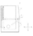
- the atomic absorption spectrophotometer 10 includes a cylindrical main body case 1 and a cylindrical chimney 2, and the chimney 2 is attached to the main body case 1 so that a lower portion is inserted into the main body case 1. It is attached.
- a restriction groove 3 is provided at the top of a pair of side walls of the main body case 1 in the left-right direction.
- the number and position of the restriction grooves 3 may be appropriately set according to the sizes and relative positions of the main body case 1 and the chimney 2.
- two restriction grooves 3 are provided on one side of the main body case side wall.
- two restriction grooves are also provided on the other side of the main body case (not shown).
- a protrusion 4 is provided at a position corresponding to the restriction groove 3 when the chimney 2 is attached to the main body case 1. As shown in FIG. 2, two protrusions 4 are provided on one side of the chimney side wall. Similarly, two protrusions are provided on the other side of the chimney side wall (not shown).
- FIGS. 1 to 3 show an example in which a restriction groove 3 is provided in a main body case 1 and a protrusion 4 is provided in a chimney 2.
- a restriction groove may be provided at the bottom of the pair of chimney side walls in the left-right direction of the chimney 2, and a protrusion may be provided at a position corresponding to the restriction groove when the chimney 2 of the main body case 1 is provided.
- the chimney 2 can be attached to the main body case 1 stably.
- the chimney escape structure of the hinge type connecting rod 5 includes a pair of connecting rods 5, and only one connecting rod 5 is shown in FIGS. Have exactly the same structure.
- each of the pair of connecting rods 5 is rotatably connected to each of the pair of chimney side walls, and the other end of each of the pair of connecting rods 5 is rotatably and movably connected to each of the pair of main body case side walls.
- narrow holes 6 extending in the front-rear direction are respectively provided at positions continuous with the other ends of the pair of connecting rods 5 on the pair of body case side walls, and the other ends of the pair of connecting rods 5 are provided at the other ends.
- a rotating shaft 7 is provided, and the rotating shaft 7 is engaged in the narrow hole 6, and the rotating shaft 7 is rotatable in the narrow hole 6 and movable back and forth.
- the connecting rod 5 When the chimney 2 is attached to the main body case 1, the connecting rod 5 is located at the position shown by the broken line in FIGS. 1 and 2, and at this time, the rotating shaft 7 provided at the other end of the connecting rod 5 has the narrow hole 6. Located in front of.
- the shape of the connecting rod 5 according to the present invention is a curved rod, but is not limited thereto. Other shapes such as a linear shape may be used.
- a ring damper for stably rotating the chimney 2 may be provided at the connection position between the chimney 2 and the main body case 1 at both ends of the connecting rod 5.
Landscapes
- Physics & Mathematics (AREA)
- Health & Medical Sciences (AREA)
- Life Sciences & Earth Sciences (AREA)
- Immunology (AREA)
- Analytical Chemistry (AREA)
- Biochemistry (AREA)
- General Health & Medical Sciences (AREA)
- General Physics & Mathematics (AREA)
- Chemical & Material Sciences (AREA)
- Pathology (AREA)
- Spectroscopy & Molecular Physics (AREA)
- Environmental & Geological Engineering (AREA)
- General Life Sciences & Earth Sciences (AREA)
- Geology (AREA)
- Nuclear Medicine, Radiotherapy & Molecular Imaging (AREA)
- Investigating Or Analysing Materials By Optical Means (AREA)
Abstract
L'invention concerne une structure de suppression de conduit de fumée de type tige à liaison articulée utilisée dans un spectrophotomètre d'absorbance atomique. Le spectrophotomètre d'absorbance atomique comprend un boîtier de corps principal cylindrique et un conduit de fumée cylindrique. Le conduit de fumée est monté sur le boîtier de corps principal de telle sorte que la partie inférieure du conduit de fumée est insérée à l'intérieur du boîtier de corps principal, des rainures de limitation sont situées au sommet d'une paire de parois latérales de boîtier de corps principal dans la direction gauche-droite du boîtier de corps principal, des parties en saillie sont situées à des positions correspondant aux rainures de limitation lorsque le conduit de fumée est monté sur le boîtier de corps principal, ou des rainures de limitation sont situées sur le fond de la paire de parois latérales de conduit de fumée sur les directions gauche et droite du conduit de fumée, les parties en saillie étant situées à des positions correspondant aux rainures de limitation lorsque le conduit de fumée est situé sur le boîtier de corps principal, et lorsque le conduit de fumée est monté sur le boîtier de corps principal, les saillies s'ajustent à l'intérieur des rainures de limitation. La structure de suppression de conduit de fumée de type tige à liaison articulée comprend une paire de tiges de liaison, une extrémité de la paire de tiges de liaison étant reliée chacune de façon rotative à la paire de parois latérales de conduit de fumée, et l'autre extrémité de la paire de tiges de liaison étant reliée chacune de façon rotative et mobile à la paire de parois latérales de boîtier de corps principal.
Applications Claiming Priority (2)
| Application Number | Priority Date | Filing Date | Title |
|---|---|---|---|
| CN201821000218.7U CN208399385U (zh) | 2018-06-27 | 2018-06-27 | 铰链式连杆的烟囱脱出结构以及原子吸收分光光度计 |
| CN201821000218.7 | 2018-06-27 |
Publications (1)
| Publication Number | Publication Date |
|---|---|
| WO2020003623A1 true WO2020003623A1 (fr) | 2020-01-02 |
Family
ID=65132378
Family Applications (1)
| Application Number | Title | Priority Date | Filing Date |
|---|---|---|---|
| PCT/JP2019/009517 Ceased WO2020003623A1 (fr) | 2018-06-27 | 2019-03-08 | Structure de suppression de conduit de fumée de type tige à liaison articulée et spectrophotomètre d'absorbance atomique |
Country Status (2)
| Country | Link |
|---|---|
| CN (1) | CN208399385U (fr) |
| WO (1) | WO2020003623A1 (fr) |
Citations (4)
| Publication number | Priority date | Publication date | Assignee | Title |
|---|---|---|---|---|
| JPS62178353U (fr) * | 1986-04-30 | 1987-11-12 | ||
| JPH08201282A (ja) * | 1995-01-23 | 1996-08-09 | Hitachi Ltd | フレームレス原子吸光用原子化装置 |
| JP2008157772A (ja) * | 2006-12-25 | 2008-07-10 | Toppan Printing Co Ltd | プラスチック試料中金属元素の分析方法 |
| CN203744192U (zh) * | 2014-02-19 | 2014-07-30 | 浙江省海洋水产研究所 | 一种石墨炉原子吸收光谱仪照明装置 |
-
2018
- 2018-06-27 CN CN201821000218.7U patent/CN208399385U/zh not_active Expired - Fee Related
-
2019
- 2019-03-08 WO PCT/JP2019/009517 patent/WO2020003623A1/fr not_active Ceased
Patent Citations (4)
| Publication number | Priority date | Publication date | Assignee | Title |
|---|---|---|---|---|
| JPS62178353U (fr) * | 1986-04-30 | 1987-11-12 | ||
| JPH08201282A (ja) * | 1995-01-23 | 1996-08-09 | Hitachi Ltd | フレームレス原子吸光用原子化装置 |
| JP2008157772A (ja) * | 2006-12-25 | 2008-07-10 | Toppan Printing Co Ltd | プラスチック試料中金属元素の分析方法 |
| CN203744192U (zh) * | 2014-02-19 | 2014-07-30 | 浙江省海洋水产研究所 | 一种石墨炉原子吸收光谱仪照明装置 |
Also Published As
| Publication number | Publication date |
|---|---|
| CN208399385U (zh) | 2019-01-18 |
Similar Documents
| Publication | Publication Date | Title |
|---|---|---|
| US10822836B2 (en) | Electric lock device for opening and closing body | |
| JP6467523B2 (ja) | 開閉体のロック装置 | |
| US9121206B2 (en) | Locking device for closing-opening member | |
| JP6598124B2 (ja) | 開閉体のロック装置 | |
| EP1462713A2 (fr) | Dispositif d'éclairage | |
| JPWO2017195557A1 (ja) | 開閉体のロック装置 | |
| WO2016150074A1 (fr) | Mécanisme de support pour clavier et tablette d'ordinateur individuel | |
| CN110650868A (zh) | 车辆用灯具 | |
| WO2020003623A1 (fr) | Structure de suppression de conduit de fumée de type tige à liaison articulée et spectrophotomètre d'absorbance atomique | |
| JP3176136U (ja) | レジスタ | |
| US5450891A (en) | Window shade mountable on both ends in similar brackets | |
| US8171940B2 (en) | Rotary cutter assembly for a lighter | |
| FI88532C (fi) | Laoshus foer doerrblad | |
| US10866138B2 (en) | Spectrophotometer | |
| JP6661864B2 (ja) | 伸縮装置 | |
| JP2008254483A (ja) | 二重ロックレバー構造 | |
| FI115949B (fi) | Järjestely komponenttien kiinnittämiseksi irrotettavasti runko-osaan | |
| EP0684424A1 (fr) | Luminaire | |
| JP4733866B2 (ja) | 投影レンズ装置及びこれを備えたスポットライト | |
| US6380519B1 (en) | Electrical oven having a housing with a turnable lid | |
| JP4374304B2 (ja) | 便座および便蓋の蝶着機構 | |
| JP2008184071A (ja) | 車輪止め構造 | |
| JP2777702B2 (ja) | 伸縮式の杖 | |
| CN203828844U (zh) | 伸缩管 | |
| JP2003057359A (ja) | センサ |
Legal Events
| Date | Code | Title | Description |
|---|---|---|---|
| 121 | Ep: the epo has been informed by wipo that ep was designated in this application |
Ref document number: 19825833 Country of ref document: EP Kind code of ref document: A1 |
|
| NENP | Non-entry into the national phase |
Ref country code: DE |
|
| 122 | Ep: pct application non-entry in european phase |
Ref document number: 19825833 Country of ref document: EP Kind code of ref document: A1 |
|
| NENP | Non-entry into the national phase |
Ref country code: JP |