WO2020003644A1 - Dispositif de détection de fuite de gaz et procédé de détection de fuite de gaz - Google Patents
Dispositif de détection de fuite de gaz et procédé de détection de fuite de gaz Download PDFInfo
- Publication number
- WO2020003644A1 WO2020003644A1 PCT/JP2019/010986 JP2019010986W WO2020003644A1 WO 2020003644 A1 WO2020003644 A1 WO 2020003644A1 JP 2019010986 W JP2019010986 W JP 2019010986W WO 2020003644 A1 WO2020003644 A1 WO 2020003644A1
- Authority
- WO
- WIPO (PCT)
- Prior art keywords
- gas
- leak
- risk
- information
- infrared image
- Prior art date
- Legal status (The legal status is an assumption and is not a legal conclusion. Google has not performed a legal analysis and makes no representation as to the accuracy of the status listed.)
- Ceased
Links
Images

Classifications
-
- G—PHYSICS
- G01—MEASURING; TESTING
- G01M—TESTING STATIC OR DYNAMIC BALANCE OF MACHINES OR STRUCTURES; TESTING OF STRUCTURES OR APPARATUS, NOT OTHERWISE PROVIDED FOR
- G01M3/00—Investigating fluid-tightness of structures
- G01M3/02—Investigating fluid-tightness of structures by using fluid or vacuum
Definitions
- the present invention relates to a leaked gas detection device and a leaked gas detection method for detecting a predetermined gas leaked into a space.
- the gas leak detection device disclosed in Patent Document 1 is a gas leak detection device that detects a gas leak in an inspection target region, and processes an infrared camera that captures an inspection target region and an infrared image that is captured by the infrared camera.
- An image processing unit; and a gas leak determination unit configured to determine a gas leak based on a processing result of the image processing unit.
- the image processing unit is configured to dynamically detect a gas leak from a plurality of infrared images arranged in time series.
- the apparatus further includes a fluctuation extracting unit that extracts a fluctuation, and the gas leak determining unit determines that a gas leak has occurred when a dynamic fluctuation is extracted by the fluctuation extracting unit.
- the gas leakage prediction and countermeasure support device disclosed in Patent Document 2 is a device for predicting a gas leakage amount and supporting the countermeasure, wherein (a) a gas leakage sensor and (b) a measurement signal of the gas leakage sensor. And (c) predicting in advance the time when the amount of leaked gas reaches the alarm level, the time when the amount of leaked gas exceeds the measurement limit, and the predicted amount of leaked gas, to prevent the occurrence of disasters and the spread of damage.
- a guidance output device for displaying the predicted leaked gas amount and the countermeasure for the gas leak, and (e) the time when the leaked gas amount reaches the alarm level, and the gas leaking amount indicates the measurement limit and the predicted leaked gas amount.
- a storage device that stores an algorithm for inferring the time to be obtained, measures for preventing occurrence of disasters and damage expansion, and information for supporting measures for evacuation guidance and production stoppage; and (f) the processing device. And an input device for searching for a measure in an interactive manner.
- the gas leak detection device disclosed in Patent Document 1 detects a gas leak based on an infrared image captured by an infrared camera, so that a wider area can be detected.
- a monitoring target such as a gas plant, a petrochemical plant, a thermal power plant, and a facility related to steelmaking. For this reason, it is not easy to recognize the location of the gas leak, and the burden on a supervisor such as a field worker is not small. Therefore, a technique for supporting the supervisor is desired to reduce the burden on the supervisor. .
- the gas leakage prediction and countermeasure support device disclosed in Patent Literature 2 discloses a time period in which a leaked gas amount reaches an alarm level, a time period in which a leaked gas amount exceeds a measurement limit, a predicted leaked gas amount, and a countermeasure for the gas leak. Is displayed, the burden on the supervisor can be reduced by referring to these. However, since the gas leak prediction and countermeasure support device disclosed in Patent Document 2 displays the leaked gas after detecting the gas, the monitor cannot monitor the gas leak when the watcher monitors the gas leak.
- the present invention has been made in view of the above circumstances, and an object of the present invention is to provide a leak gas detection device and a leak gas detection method capable of supporting a monitoring operation of a monitor when monitoring a gas leak. It is.
- a leaked gas detection device and a leaked gas detection method provide an infrared image generated by capturing an infrared light image of a subject with an infrared light imaging device. Acquiring data, acquiring imaging range information relating to an imaging range of the infrared light imaging device, and obtaining infrared data of the infrared image data based on the acquired imaging range information and gas equipment information stored in a storage unit. A gas facility reflected in the image is extracted, a risk of gas leakage for the extracted gas facility is obtained as leak risk information, and the obtained leak risk information is output.
- FIG. 4 is a diagram for explaining a gas leakage risk table stored in a leakage gas detection device of the leakage gas detection system. It is a flowchart which shows the operation
- FIG. 1 is a block diagram showing a configuration of the leaked gas detection system in the embodiment.
- FIG. 2 is a diagram for explaining a gas leak risk table stored in the leak gas detection device of the leak gas detection system.
- the leaked gas detection system is configured to detect a gas facility from the gas facility based on an infrared image generated by capturing an infrared light image of the subject with an infrared light imaging device using the monitored gas facility as a subject.
- This is a system for detecting a leaked gas when a gas leaks.
- a leaked gas detection system includes, for example, an infrared light imaging device CA, an imaging range detection device RD, and a leaked gas detection device GD as shown in FIG.
- the range detection device RD and the leaked gas detection device GD are connected by wire or wirelessly so that data can be exchanged with each other.
- the infrared light imaging device CA captures an infrared optical image of a subject (infrared light image of the subject) to generate infrared image data (infrared image data), and transmits the infrared image data to a leaked gas. This is a device for outputting to the detection device GD.
- the infrared light imaging device CA is an imaging optical system that forms an infrared light image of a subject on a predetermined imaging surface, and the light receiving surface is arranged to coincide with the imaging surface.
- An area image sensor that converts an infrared light image of the subject into an electrical signal; and data representing an infrared image of the subject (an infrared image of the subject) by performing image processing on an output of the area image sensor.
- a digital infrared camera including an image processing unit for generating infrared image data.
- the area image sensor is, for example, an image sensor having a light receiving sensitivity at a wavelength of about 1 to 5 ⁇ m, such as a cooled infrared image sensor using InSb when the target gas to be detected as a leak gas is a hydrocarbon-related gas. Is preferred.
- the infrared light imaging device CA in order to obtain the imaging range of the infrared light imaging device CA, the infrared light imaging device CA outputs angle-of-view information indicating the angle of view of the infrared light imaging device CA to the leaked gas detection device GD. Note that the infrared light imaging device CA may output the angle-of-view information to the leaked gas detection device GD via the imaging range detection device RD.
- the imaging range detection device RD is a device that measures imaging range information regarding an imaging range of the infrared light imaging device CA and outputs the imaging range information to the infrared light imaging device CA.
- the imaging range information is information for obtaining an imaging range of the infrared light imaging device CA.
- imaging position information indicating the position of the infrared light imaging device CA, the infrared light imaging device CA It is imaging direction information indicating an imaging direction of CA and the view angle information indicating an angle of view of the infrared light imaging device CA.
- the imaging direction information is a line-of-sight direction (optical axis direction) of the infrared light imaging device CA, azimuth information indicating a direction in a horizontal plane of the infrared light imaging device CA, and a direction information in a vertical plane of the infrared light imaging device CA.
- This is angle information indicating the direction.
- the imaging range detection device RD includes, for example, a GPS sensor RDS-1, an azimuth sensor RDS-2, and an angle sensor RDS-3.
- the GPS (Global Positioning System) sensor RDS-121 measures the current position of the infrared light imaging device CA on the earth by a satellite positioning system for measuring the current position on the earth, and the positioning result (position ( (Latitude, longitude, altitude)) is output to the infrared light imaging device CA as the imaging position information of the imaging range information.
- the GPS sensor RDS-1 may be a GPS sensor having a correction function for correcting an error, such as a DGPS (Differential @ GPS) sensor.
- the azimuth sensor RDS-2 is a device that measures the current azimuth of the infrared light imaging device CA on the earth and outputs the measurement result (azimuth) to the infrared light imaging device CA as azimuth information of the imaging range information. Yes, for example, with a three-axis compass (three-axis geomagnetic sensor).
- the angle sensor RDS-3 is a device that measures the current angle of the infrared light imaging device CA on the earth and outputs the measurement result (angle) to the infrared light imaging device CA as angle information of the imaging range information. Yes, for example, it is provided with an inclination sensor or the like for measuring the inclination by measuring the gravitational acceleration of the earth.
- the imaging range detection device RD may be incorporated in the infrared imaging device CA in order to obtain the imaging range of the infrared imaging device CA. It may be attached to the imaging device CA.
- the leak gas detection device GD is a device that detects a leak gas based on an infrared image.
- a control processing unit 1 a storage unit 2, a first acquisition unit 3, 2 comprises an acquisition unit 4 and an output unit 5.
- the first acquisition unit 3 is connected to the infrared light imaging device CA by wire or wireless so that data can be exchanged, and is also connected to the control processing unit 1. According to the control of the control processing unit 1, the first acquisition unit 3 converts the infrared light image of the subject into a red light.
- This is a circuit that acquires infrared image data generated by imaging with the external light imaging device CA from the infrared light imaging device CA.
- the second acquisition unit 4 is connected to the infrared light imaging device CA by wire or wireless so as to be able to exchange data and is connected to the control processing unit 1.
- 9 is a circuit for acquiring imaging range information regarding an imaging range.
- the first and second acquisition units 3 and 4 acquire the infrared image data and the imaging range information substantially in synchronization.
- the first and second acquisition units 3 and 4 are, for example, in the case of a wired connection, respectively, are interface circuits or the like that comply with the RS-232C standard, the RS-485 standard, the IEEE 802.11 standard, and the like. Further, for example, in the case of wireless connection, the first and second acquisition units 3 and 4 are provided with a communication card that communicates with the infrared light imaging device CA via a general line network such as a mobile communication network, or an Ethernet. A communication interface circuit that communicates with the infrared light imaging device CA via a LAN (Local Area Network) such as a registered trademark, for example, in accordance with the IEEE 802.11 standard or the like may be used.
- the first and second acquisition units 3 and 4 may be separate units, but may also be used separately, and may be one interface circuit, one communication card, or one communication interface circuit. Is also good.
- the output unit 5 is a device that is connected to the control processing unit 1 and outputs the leak risk information obtained by the risk estimation processing unit under the control of the control processing unit 1.
- the output unit 5 is, for example, a display device such as a CRT display, a liquid crystal display, and an organic EL display, and displays leakage risk information obtained by the risk estimation processing unit.
- the output unit 5 may be, for example, the communication card, the communication interface circuit, or the like, like the first and second acquisition units 3, 4, and in this case, for example, a so-called smartphone or a device with a communication function
- the leakage risk information obtained by the risk estimation processing unit is displayed on a communication destination terminal device such as a personal computer.
- the storage unit 2 is a circuit that is connected to the control processing unit 1 and stores various predetermined programs and various predetermined data under the control of the control processing unit 1.
- the various predetermined programs include, for example, control processing programs such as a control program, a facility extraction program, a risk estimation processing program, and a gas detection processing program.
- the control program is a program for controlling each of the units 2 to 5 of the leak gas detection device GD.
- the facility extraction program is based on the imaging range information acquired by the second acquisition unit 4 and the gas facility information described later stored in the storage unit 2, based on the infrared image of the infrared image data acquired by the first acquisition unit 3. This is a program to extract the gas facilities reflected in.
- the risk estimation processing program is a program that obtains, as leakage risk information, a gas leakage risk for the gas equipment extracted by the equipment extraction program.
- the gas detection processing program is a program for detecting a leaked gas based on the infrared image of the infrared image data acquired by the first acquisition unit 3.
- the various types of predetermined data include the infrared image data acquired by the first acquisition unit 3, the imaging range information acquired by the second acquisition unit 4, and gas facility information related to the gas facility to be monitored. Contains the data needed to perform
- the gas facility information is, for example, the three-dimensional design information of the gas facility and the gas leakage risk indicating the degree of gas leakage risk to the gas facility.
- the storage unit 2 includes, for example, a ROM (Read Only Memory) which is a nonvolatile storage element, an EEPROM (Electrically Erasable Programmable Read Only Memory) which is a rewritable nonvolatile storage element, and the like.
- the storage unit 2 includes a RAM (Random Access Memory) serving as a working memory of the so-called control processing unit 1 for storing data and the like generated during execution of the predetermined program.
- the storage unit 2 functionally includes a gas facility information storage unit 21 for storing the gas facility information.
- the gas facility information storage unit 21 stores the three-dimensional design information and the gas leakage risk.
- a three-dimensional design information storage unit 211 and a leakage risk storage unit 212 are functionally provided.
- the storage unit 2 may include a hard disk device having a relatively large storage capacity.
- the gas facility information storage unit 21 stores the gas facility information.
- the gas equipment includes, for example, a pipe through which a gas flows, a tank that stores the gas, a valve that adjusts the flow rate of the gas, and opens and closes the flow of the gas.
- the gas facility information storage unit 21 stores gas facility information in association with each of a plurality of gas facilities.
- the three-dimensional design information storage unit 211 stores the three-dimensional design information of the gas equipment in advance.
- the three-dimensional design information includes, for example, a gas facility ID, such as a name and a member number of the gas facility, which is an identifier for identifying and identifying the gas facility, a model number of the gas facility, and a location indicating an arrangement position of the gas facility.
- the three-dimensional design information storage unit 211 stores three-dimensional design information in association with each of a plurality of gas facilities (gas facility IDs).
- the arrangement position information may be represented by latitude, longitude and altitude, or the arrangement position information Is represented by a coordinate position of a coordinate system (local coordinate system) used in the three-dimensional design of gas equipment.
- the coordinate position of the local coordinate system is represented by latitude, The latitude, longitude, and altitude may be converted to the coordinate position in the local coordinate system.
- the leakage risk storage unit 212 stores in advance a gas leakage risk indicating a degree of risk of gas leakage to gas equipment.
- the leakage risk storage unit 212 stores the gas leakage risk in association with each of a plurality of gas facilities (gas facility IDs).
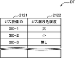
- the risk of gas leakage is determined in advance for each gas facility in accordance with the gas leakage probability predicted in design. For example, the gas leakage risk is set in three stages: “large”, the gas leakage probability is relatively high, “small”, the gas leakage probability is relatively low, and “none”, where the gas leakage probability is 0. .
- the gas leakage risk is stored in the leakage risk storage unit 212 in a table format.
- the gas leakage risk table DT for registering the gas leakage risk includes, for example, a gas facility ID field 2121 for registering a gas facility ID and a gas facility ID registered in the gas facility ID field 2121 as shown in FIG. And a gas leak risk field 2122 for registering a gas leak risk of a gas facility having a gas facility, and has a record for each gas facility (gas facility ID).
- the control processing unit 1 controls each of the units 2 to 5 of the leak gas detection device GD according to the function of each unit, detects a leak gas based on an infrared image, and outputs leak risk information of gas equipment. It is.
- the control processing unit 1 includes, for example, a CPU and its peripheral circuits.
- the control processing unit 1 functionally includes a control unit 11, a facility extraction unit 12, a risk estimation processing unit 13, and a gas detection processing unit 14 by executing the control processing program.
- the control unit 11 controls each of the units 2 to 5 of the leak gas detection device GD according to the function of each unit, and controls the entire control of the leak gas detection device GD.
- the equipment extraction unit 12 is reflected in the infrared image of the infrared image data based on the imaging range information acquired by the second acquisition unit 4 and the gas equipment information stored in the gas equipment information storage unit 21 of the storage unit 2. This is to extract the gas facilities that are being used. More specifically, the facility extraction unit 12 obtains the imaging range of the infrared light imaging device CA based on the imaging range information acquired by the second acquisition unit 4 and stores the acquired imaging range in the gas facility information storage unit 21 of the storage unit 2. Based on the obtained gas facility information, the first acquisition unit 3 acquires a gas facility within the imaging range of the infrared light imaging device CA substantially in synchronization with the imaging range information acquired by the second acquisition unit 4.
- the facility extracting unit 12 firstly determines the line-of-sight direction (optical axis) of the infrared light imaging device CA from the imaging position information, azimuth information, and angle information acquired by the second acquisition unit 4. Direction), and from the obtained line-of-sight direction (optical axis direction) of the infrared light imaging device CA and the angle-of-view information acquired by the second acquisition unit 4, an imaging range of the infrared light imaging device CA is determined.
- the equipment extracting unit 12 captures an image within the obtained photographing range from the three-dimensional design information (arrangement position information and shape information) stored in the three-dimensional design information storage unit 211 of the gas equipment information storage unit 21.
- the gas facility that has been included is determined, and the gas facility ID of the determined gas facility is determined.
- the risk estimation processing unit 13 obtains the risk of gas leakage from the gas equipment extracted by the equipment extraction unit 12 as leakage risk information. More specifically, the risk estimation processing unit 13 determines the risk of gas leakage for the gas equipment extracted by the equipment extraction unit 12 based on the gas equipment information stored in the gas equipment information storage unit 21 of the storage unit 2. Request as leak risk information. More specifically, in the present embodiment, for example, the risk estimation processing unit 13 extracts the gas equipment of the gas equipment extracted by the equipment extraction unit 13 from the gas leakage risk table DT stored in the leakage risk storage unit 212. A record whose ID is to be registered in the gas facility ID field 2121 is selected (searched), and the gas leak risk registered in the gas leak risk field 2122 of the selected record is extracted as the leak risk information. As a result, leak risk information is required.
- the gas detection processing unit 14 detects a leak gas based on an infrared image.
- a method disclosed in Japanese Patent No. 5343054 Japanese Patent Application Laid-Open No. 2012-058093
- a method disclosed in International Publication No. 2017/073426 a method disclosed in International Publication No.
- a known method such as the method disclosed in Japanese Patent Application Laid-Open No. 073430 is used.
- the control processing unit 1 obtains the infrared image data of the infrared image data acquired by the first acquisition unit 3 from the output unit 5 based on the infrared image data by the control unit 11. It also outputs leak risk information and, if leak gas is detected based on the infrared image data, outputs leak gas detection.
- the control unit 11 displays an infrared image of the infrared image data acquired by the first acquisition unit 3 on a display device serving as the output unit 5, and displays the infrared image.
- the leak risk information obtained based on the data is also displayed, and when the leak gas is detected based on the infrared image data, the detection of the leak gas is also displayed.
- the leak risk information may be displayed, for example, as a list of texts in which the names and member numbers of the gas equipment having the gas equipment IDs are associated with the risk of gas leak.
- the leak risk information may display an image of a gas facility having a gas facility ID in a display mode according to a gas leak risk. For example, the shade of the display color is changed according to the gas leakage risk, and when the gas leakage risk is “large”, the image of the gas facility is displayed relatively dark and the gas leakage risk is “small”. ", The image of the gas facility is displayed relatively lightly.
- the hue of the display color is changed according to the gas leakage risk, and when the gas leakage risk is “large”, the image of the gas facility is displayed in red, and the gas leakage risk is “small”. , The image of the gas facility is displayed in yellow.
- the leakage risk information obtained by the risk estimation processing unit 13 is superimposed and displayed on the infrared image of the infrared image data.
- the output unit 5 is the communication card, the communication interface circuit, or the like, the display is performed on the display device of the communication destination terminal device in the same manner as described above.
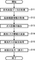
- FIG. 3 is a flowchart showing the operation of the leaked gas detection device.
- the control processing unit 1 functionally includes a control unit 11, a facility extraction unit 12, a risk estimation processing unit 13, and a gas detection processing unit 14 by executing the control processing program.
- the infrared light imaging device CA, the imaging range detection device RD, and the leakage gas detection device GD in the leak gas detection system respectively repeatedly execute the following operation at a predetermined sampling interval such as a frame interval or several frame intervals. As a result, leak risk information of a monitoring target is obtained, and leak gas is detected.
- the control unit 11 of the control processing unit 1 uses the infrared light imaging device CA to capture infrared image data generated by the control unit 11 of the control processing unit 1.
- the first acquisition unit 1 acquires from the imaging device CA (S11), and the control unit 11 of the control processing unit 1 acquires the imaging range information on the imaging range of the infrared light imaging device CA by the second acquisition unit 4 (S11). S12). It is assumed that the infrared image data acquired in step S11 and the imaging range information acquired in step S12 are substantially synchronized with each other.
- the leaked gas detection device GD simultaneously sends a transmission command to each of the infrared light imaging device CA and the imaging range detection device RD, and the infrared light imaging device CA and the imaging range detection device RD respond accordingly.
- the infrared image data and the imaging range information are substantially synchronized.
- the infrared light imaging device CA sends infrared image data associated with the generation time to the leaked gas detection device GD
- the imaging range detection device RD sends imaging range information associated with the measurement time
- the leak gas detection device GD can substantially synchronize the infrared image data with the imaging range information.
- the process S12 is performed after the process S11 is performed.
- the process S11 may be performed after the process S12 is performed, or each of the processes S12 and S11 may be performed. The processing may be performed concurrently.
- the leaked gas detection device GD uses the equipment extraction unit 12 of the control processing unit 1 to obtain the imaging range information acquired by the second acquisition unit 4 and the gas equipment information stored in the gas equipment information storage unit 21 of the storage unit 2. Is extracted, the gas facilities reflected in the infrared image of the infrared image data are extracted (S13).
- the equipment extracting unit 12 first obtains the line-of-sight direction of the infrared light imaging device CA from the imaging position information, the azimuth information, and the angle information acquired by the second acquiring unit 4.
- An imaging range of the infrared light imaging device CA is obtained from the line-of-sight direction of the imaging device CA and the angle-of-view information acquired by the second acquisition unit 4.
- the equipment extracting unit 12 captures an image within the obtained photographing range from the three-dimensional design information (arrangement position information and shape information) stored in the three-dimensional design information storage unit 211 of the gas equipment information storage unit 21.
- the gas facility that has been included is determined, and the gas facility ID of the determined gas facility is determined.
- the leak gas detection device GD obtains, as leak risk information, the risk of gas leak for the gas equipment extracted by the equipment extractor 12 by the risk estimation processor 13 of the control processor 1 (S14).
- the risk estimation processing unit 13 converts the gas facility ID of the gas facility extracted by the facility extraction unit 13 from the gas leakage risk table DT stored in the leakage risk storage unit 212 into a gas facility ID field.
- the record to be registered in 2121 is selected (searched), and the gas leak risk registered in the gas leak risk field 2122 of the selected record is extracted as the leak risk information.
- the gas leakage risk is extracted as zero, one, or a plurality according to the imaging range of the infrared light imaging device CA.
- the leaked gas detection device GD detects a leaked gas by the gas detection processing unit 14 of the control processing unit 1 based on the infrared image of the infrared image data (S16).
- the control unit 11 of the control processing unit 1 outputs the infrared image of the infrared image data acquired by the first acquisition unit 3 from the output unit 5, the leakage gas detection device GD Is output based on the infrared image data, and if leak gas is detected based on the infrared image data, detection of the leak gas is also output (S16), and the current process is terminated. I do.
- the control unit 11 displays the infrared image of the infrared image data acquired by the first acquisition unit 3 on a display device as the output unit 5, and displays the leakage image obtained based on the infrared image data.
- Risk information is also displayed, and when leak gas is detected based on the infrared image data, leak gas detection is also displayed.
- the hue of the display color is changed according to the gas leak risk, so that the leak risk information is superimposed and displayed on the infrared image of the infrared image data.
- the control unit 11 causes the terminal device to display the infrared image of the infrared image data acquired by the first acquisition unit 3 and changes the hue of the display color according to the risk of gas leakage.
- the leak risk information obtained based on the infrared image data is also displayed on the terminal device so that the leak risk information is superimposed and displayed on the infrared image of the image data, and further based on the infrared image data. If a leaked gas is detected, a communication signal to be displayed on the terminal device for the detection of the leaked gas is transmitted from the communication interface circuit as the output unit 5 to the terminal device.
- the leaked gas detection system As described above, the leaked gas detection system according to the present embodiment, the leaked gas detection device GD used therein, and the leaked gas detection method mounted on the leaked gas detection system are reflected on the infrared image of the acquired infrared image data.
- the extracted gas equipment is extracted, and the risk of gas leakage for the extracted gas equipment is determined and output as leakage risk information. For this reason, the observer can see the infrared image of the infrared image data while referring to the leakage risk information, so that the observer can watch a portion of the infrared image at a high risk of gas leakage. Therefore, when the leaked gas is detected and the leaked gas is displayed on the infrared image, the possibility of overlooking the detected leaked gas can be reduced.
- the observer can simply observe a portion of the infrared image where there is almost no risk of gas leakage, so that the infrared image can be efficiently observed.
- the leaked gas detection system, the leaked gas detection device GD, and the leaked gas detection method can support a monitoring operation of a monitor when monitoring a gas leak.
- a leak gas detection system that outputs a gas leak risk, a leak gas detection device GD, and a leak gas detection method.
- the observer can observe an infrared image according to the risk of gas leak.
- the imaging range detection device RD measures imaging range information for obtaining an imaging range when the infrared light imaging device CA generates infrared image data. . For this reason, the line-of-sight direction (optical axis direction) of the installed infrared light imaging device CA is changed by remote control, or the handy type infrared light imaging device CA is carried by an operator and moves while moving.
- the leaked gas detection system, the leaked gas detection device GD, and the leaked gas detection method appropriately extract gas facilities reflected in the infrared image of the infrared image data, The risk of gas leakage for the extracted gas equipment can be appropriately obtained and output as leakage risk information.
- the leak risk information is the gas leak risk, but instead, or in addition to this, the leak history information indicating the fact of the gas leak that occurred in the past. good.
- the leaked gas detection device GD of such a leaked gas detection system further includes an input unit 6 as shown by a broken line in FIG. 213 is further provided.
- the input unit 6 is connected to the control processing unit 1 and is necessary for performing various commands such as a command for instructing start of monitoring, and monitoring of gas leakage such as a name of a monitoring target and leak history information.
- This is a device for inputting various kinds of data to the leak gas detection device GD, for example, a keyboard and a mouse.
- the leak history information storage unit 213 stores the leak history information input from the input unit 6.
- the leak history information is information indicating a fact of a gas leak that occurred in the past, that is, information indicating a past performance of the gas leak, and includes at least information indicating “when” and “at which equipment” the gas leak occurred.
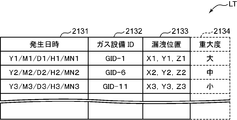
- FIG. 4 is a diagram for explaining a leak history information table stored in a leak gas detection device according to a modified embodiment.
- the leak history information is stored in the leak history information storage unit 213 in a table format.
- the leak history information table LT for registering the leak history information includes, for example, as shown in FIG. 4, an occurrence date and time field 2131 for registering the time when the gas leak occurred in the year, month, day and time, A gas facility ID field 2132 for registering the gas facility ID of the facility and a leak position field 2133 for registering the leak location of the gas leak are provided, and a record is provided each time the occurrence of gas leak is recorded (input).
- a monitor instructs input of leak history information.
- the leaked gas detection device GD includes a monitoring target image area for displaying a monitoring target image, and an occurrence date / time input field for inputting the occurrence date / time.
- a history input screen is displayed on a display device as the output unit 5. The monitor inputs the date and time of occurrence in the date and time input field in the input date and time in the date and time input field, and designates the leakage position on the image of the monitoring target displayed in the monitoring target image area with, for example, a mouse cursor. .
- the image of the monitoring target displayed in the monitoring target image area is appropriately changed by, for example, scrolling or the like.
- the leaked gas detection device GD uses the three-dimensional design information stored in the three-dimensional design information storage unit 211 by the control processing unit 1 to detect the gas equipment corresponding to the specified leak position. Is selected (searched), and the coordinate values of the gas facility ID and the leak position are obtained. Then, the leaked gas detection device GD adds a new record to the leaked history information table LT stored in the leaked history information storage unit 213 by the control processing unit 1, and adds the added occurrence date / time field 2131, gas equipment ID. The occurrence date and time, the gas facility ID, and the coordinate value of the leak position are registered in the field 2132 and the leak position field 2133, respectively. As a result, the leak history information is input to the leak gas detection device GD and recorded (stored).
- the risk estimation processing unit 13 performs the processing based on the leak history information stored in the leak history information storage unit 213 in the gas facility information storage unit 21 of the storage unit 2.
- the configuration is such that the fact of gas leakage to the gas equipment extracted by the equipment extraction unit 12 is obtained as the leakage risk information.
- the risk estimation processing unit 13 performs processing on the gas equipment extracted by the equipment extraction unit 12 based on the leak history information stored in the leak history information storage unit 213.
- the fact of gas leak is obtained as the leak risk information.
- the risk estimation processing unit 13 uses the gas facility ID of the gas facility extracted by the facility extraction unit 13 from the leakage history information table LT stored in the leakage history information storage unit 213. Is determined in the gas facility ID field 2132, and if so, the fact of gas leakage to the gas facility having this gas facility ID is used as the leakage risk information.
- the control unit 11 converts the image of the gas facility having the gas facility ID for which the leakage risk information is determined to be different in shade, hue, and the like.
- the display is performed in a display mode different from the display mode in the image of the gas facility.
- the leakage risk information obtained by the risk estimation processing unit 13 is superimposed and displayed on the infrared image of the infrared image data.
- a leak gas detection system a leak gas detection device GD, and a leak gas detection method that output the fact of gas leak based on the history.
- the observer can observe an infrared image in accordance with the fact of the gas leak based on the history.
- the risk estimation processing unit 13 stores the gas stored in the leak risk storage unit 212 in the gas facility information storage unit 21 of the storage unit 2. Based on the leak risk, the gas leak risk for the gas equipment extracted by the equipment extracting unit 12 and the leak history information stored in the leak history information storage unit 213 in the gas equipment information storage unit 21 of the storage unit 2 are stored. On the basis of the leakage risk information, each fact of gas leakage to the gas equipment extracted by the equipment extraction unit 12 is obtained.
- the risk estimation processing unit 13 stores the gas leak risk and the leak history information stored in the leak risk storage unit 212 and the leak history information storage unit 213, respectively. Based on the information, the gas leakage risk and the fact of gas leakage for the gas equipment extracted by the equipment extraction unit 12 are obtained as the leak risk information. More specifically, in the present embodiment, the risk estimation processing unit 13 extracts the gas equipment of the gas equipment extracted by the equipment extraction unit 13 from the gas leakage risk table DT stored in the leakage risk storage unit 212.
- the processing unit 13 has a record for registering the gas facility ID of the gas facility extracted by the facility extracting unit 13 in the gas facility ID field 2132 from the leakage history information table LT stored in the leakage history information storage unit 213. It is determined whether or not the gas equipment having the gas equipment ID has a gas leak, if any. And leakage risk information.
- the output unit 5 is a display device
- the control unit 11 converts the image of the gas facility having the gas facility ID for which the leakage risk information is determined to be different in shade, hue, and the like. It is displayed in a display mode different from the display mode in the image of the gas facility.
- the leakage risk information obtained by the risk estimation processing unit 13 is superimposed and displayed on the infrared image of the infrared image data.
- a leak gas detection system a leak gas detection device GD, and a leak gas detection method that output the fact of gas leak based on the gas leak risk and history.
- the observer can observe an infrared image according to the gas leak risk and the fact of gas leak based on the history.
- the number of occurrences of gas leaks can be counted (counted) for each gas facility from the leak history information, and the risk of gas leakage can be reconsidered with reference to the number of occurrences.
- the leak history information may include a severity indicating a degree of the severity of the gas leak.
- the magnitude is determined at a plurality of levels (for example, three levels of large, medium, and small) in accordance with, for example, the size and amount of leakage of the gas cloud of the leaked gas.
- the severity is recorded (stored) in the leak history information storage unit 213 every time a gas leak occurs.
- the leakage history information table LT further includes a severity field 2134 for registering the severity.
- the leak history input screen further includes a severity input field for inputting the severity, and the severity input in the severity input field is displayed in the severity field 2134. Is registered and recorded (stored).
- the leak gas detection device GD since the leak history information includes the severity, the risk of gas leakage is reconsidered by taking the severity into consideration, or the severity is taken into consideration. To observe infrared images.
- the leaked gas detection device is a device that detects leaked gas based on an infrared image, and detects infrared image data generated by capturing an infrared light image of a subject with an infrared light imaging device.
- a first acquisition unit that acquires, a second acquisition unit that acquires imaging range information about an imaging range of the infrared light imaging device, a storage unit that stores gas equipment information about gas equipment to be monitored, and the second acquisition.
- a facility extraction unit that extracts gas facilities reflected in an infrared image of the infrared image data based on the imaging range information acquired by the unit and the gas facility information stored in the storage unit; and the facility extraction unit.
- the imaging range information is information for obtaining an imaging range of the infrared light imaging device.
- the imaging range information includes imaging position information indicating a position of the infrared light imaging device, imaging direction information indicating an imaging direction of the infrared light imaging device, and an image indicating an angle of view of the infrared light imaging device. Angle information.
- the gas equipment includes a pipe, a tank, a valve, and the like.
- the gas facility information is three-dimensional design information of the gas facility and a gas leak risk level indicating a degree of gas leak risk to the gas facility.
- the three-dimensional design information is arrangement position information indicating an arrangement position of the gas equipment and shape information indicating a shape of the gas equipment.
- the gas leakage risk is determined in advance in accordance with a gas leakage probability predicted in design.
- the equipment extraction unit obtains an imaging range of the infrared light imaging device based on imaging range information acquired by the second acquisition unit, and stores the imaging range in the storage unit.
- the output unit is a display unit that performs display, and superimposes and displays leak risk information obtained by a risk estimation processing unit on an infrared image of the infrared image data. I do.
- Such a leaked gas detection device extracts a gas facility reflected in an infrared image of the acquired infrared image data, obtains a risk of gas leak from the extracted gas facility, and outputs it as leak risk information. For this reason, the observer can see the infrared image of the infrared image data while referring to the leakage risk information, so that the observer can watch a portion of the infrared image at a high risk of gas leakage. Therefore, when the leaked gas is detected and the leaked gas is displayed on the infrared image, the possibility of overlooking the detected leaked gas can be reduced.
- the observer can simply observe a portion of the infrared image where there is almost no risk of gas leakage, so that the infrared image can be efficiently observed.
- the above-described leaked gas detection device can support a monitoring operation of a monitor when monitoring a gas leak.
- the gas facility information indicates a gas leak risk indicating a degree of risk of gas leak to the gas facility, and indicates a fact of a gas leak that has occurred in the past.
- the risk estimation processing unit includes at least one of the leak history information and the risk estimation processing unit, based on at least one of the gas leak risk and the leak history information in the gas facility information stored in the storage unit. And at least one of gas leak facts is obtained as the leak risk information.
- the gas facility information is three-dimensional design information of the gas facility, and a gas leak risk level indicating a degree of risk of gas leak to the gas facility.
- the estimation processing unit obtains, as the leakage risk information, a gas leakage risk corresponding to the gas equipment extracted by the equipment extracting unit based on the gas equipment information stored in the storage unit.
- the gas facility information is three-dimensional design information of the gas facility, and leak history information indicating a fact of a gas leak that occurred in the past, and the risk estimation processing unit The fact of gas leakage corresponding to the gas equipment extracted by the equipment extraction unit is obtained as the leakage risk information based on the gas equipment information stored in the storage unit.
- the gas facility information is three-dimensional design information of the gas facility, a gas leak risk level indicating a degree of gas leak risk to the gas facility, and a gas leak risk that has occurred in the past.
- Leakage history information representing the fact of gas leakage
- the risk estimation processing unit is a gas leak risk corresponding to the gas equipment extracted by the equipment extraction unit based on the gas equipment information stored in the storage unit and The fact of gas leak is obtained as the leak risk information.
- a leaked gas detection device that outputs the risk of gas leakage can be provided.
- the observer can observe an infrared image according to the risk of gas leak.
- the observer can observe an infrared image according to the fact of gas leak based on the history.
- a leaked gas detection device that outputs the gas leakage risk and the fact of the gas leakage based on the history can be provided.
- the observer can observe an infrared image according to the risk of gas leak and the fact of gas leak based on the history.
- the leak history information includes a severity that indicates a degree of the gas leak.
- the above-described leaked gas detection device further includes an input unit for inputting the leak history information.
- a leaked gas detection device further including an input unit for inputting leak history information.
- a leak gas detection method is a method of detecting a leak gas based on an infrared image, and an infrared image generated by capturing an infrared light image of a subject with an infrared light imaging device.
- the equipment extraction step of extracting the gas equipment reflected in the infrared image of the infrared image data, and the risk of gas leakage for the gas equipment extracted in the equipment extraction step is a leak risk information
- a display step of displaying on the display unit the leakage risk information obtained in the risk estimation processing step is a leak risk information
- gas facilities appearing in the infrared image of the acquired infrared image data are extracted, and a risk of gas leakage for the extracted gas facilities is obtained and output as leak risk information.
- the observer can see the infrared image of the infrared image data while referring to the leakage risk information, so that the observer can watch a portion of the infrared image at a high risk of gas leakage. Therefore, when the leaked gas is detected and the leaked gas is displayed on the infrared image, the possibility of overlooking the detected leaked gas can be reduced.
- the observer can simply observe a portion of the infrared image where there is almost no risk of gas leakage, so that the infrared image can be efficiently observed.
- the above-described method for detecting a leaked gas can support a monitoring operation of a monitor when monitoring a gas leak.
- the present invention it is possible to provide a leaked gas detection device and a leaked gas detection method for detecting a predetermined gas leaked into a space.
Landscapes
- Physics & Mathematics (AREA)
- General Physics & Mathematics (AREA)
- Examining Or Testing Airtightness (AREA)
- Emergency Alarm Devices (AREA)
Abstract
Ce dispositif et ce procédé de détection de fuite de gaz : obtiennent des données d'image infrarouge générées par capture d'images infrarouge d'un sujet en utilisant un dispositif d'imagerie infrarouge ; obtiennent des informations de plage d'imagerie concernant la plage d'imagerie du dispositif d'image infrarouge ; extraient un équipement de gaz schématisé dans les images infrarouge dans les données d'image infrarouge, sur la base des informations de plage d'imagerie obtenues et des informations d'équipement de gaz stockées dans l'unité de stockage ; trouvent le risque de fuite de gaz pour l'équipement de gaz extrait, en tant qu'informations de risque de fuite ; et délivrent en sortie les informations de risque de fuite trouvées.
Applications Claiming Priority (2)
| Application Number | Priority Date | Filing Date | Title |
|---|---|---|---|
| JP2018-120387 | 2018-06-26 | ||
| JP2018120387 | 2018-06-26 |
Publications (1)
| Publication Number | Publication Date |
|---|---|
| WO2020003644A1 true WO2020003644A1 (fr) | 2020-01-02 |
Family
ID=68984771
Family Applications (1)
| Application Number | Title | Priority Date | Filing Date |
|---|---|---|---|
| PCT/JP2019/010986 Ceased WO2020003644A1 (fr) | 2018-06-26 | 2019-03-15 | Dispositif de détection de fuite de gaz et procédé de détection de fuite de gaz |
Country Status (1)
| Country | Link |
|---|---|
| WO (1) | WO2020003644A1 (fr) |
Cited By (3)
| Publication number | Priority date | Publication date | Assignee | Title |
|---|---|---|---|---|
| CN112748112A (zh) * | 2020-12-10 | 2021-05-04 | 中广核核电运营有限公司 | 一种气体泄漏量测量装置 |
| WO2021181675A1 (fr) * | 2020-03-13 | 2021-09-16 | コニカミノルタ株式会社 | Système et procédé de gestion d'inspection du gaz, et programme |
| US20240219255A1 (en) * | 2022-12-29 | 2024-07-04 | Schlumberger Technology Corporation | Detecting gas leaks from image data and leak detection models |
Citations (3)
| Publication number | Priority date | Publication date | Assignee | Title |
|---|---|---|---|---|
| JP2009042965A (ja) * | 2007-08-08 | 2009-02-26 | Shikoku Electric Power Co Inc | 車載型漏洩ガス検知システムおよび方法 |
| JP2013222335A (ja) * | 2012-04-17 | 2013-10-28 | Hitachi Ltd | 対象物特定システム、対象物特定サーバ及び対象物特定端末 |
| WO2018043417A1 (fr) * | 2016-08-30 | 2018-03-08 | コニカミノルタ株式会社 | Dispositif d'évaluation de tuyauterie, procédé d'évaluation de tuyauterie et programme d'évaluation de tuyauterie |
-
2019
- 2019-03-15 WO PCT/JP2019/010986 patent/WO2020003644A1/fr not_active Ceased
Patent Citations (3)
| Publication number | Priority date | Publication date | Assignee | Title |
|---|---|---|---|---|
| JP2009042965A (ja) * | 2007-08-08 | 2009-02-26 | Shikoku Electric Power Co Inc | 車載型漏洩ガス検知システムおよび方法 |
| JP2013222335A (ja) * | 2012-04-17 | 2013-10-28 | Hitachi Ltd | 対象物特定システム、対象物特定サーバ及び対象物特定端末 |
| WO2018043417A1 (fr) * | 2016-08-30 | 2018-03-08 | コニカミノルタ株式会社 | Dispositif d'évaluation de tuyauterie, procédé d'évaluation de tuyauterie et programme d'évaluation de tuyauterie |
Cited By (5)
| Publication number | Priority date | Publication date | Assignee | Title |
|---|---|---|---|---|
| WO2021181675A1 (fr) * | 2020-03-13 | 2021-09-16 | コニカミノルタ株式会社 | Système et procédé de gestion d'inspection du gaz, et programme |
| US12146812B2 (en) | 2020-03-13 | 2024-11-19 | Konica Minolta, Inc. | Gas inspection management system, gas inspection management method, and instructions for gas inspection management |
| CN112748112A (zh) * | 2020-12-10 | 2021-05-04 | 中广核核电运营有限公司 | 一种气体泄漏量测量装置 |
| US20240219255A1 (en) * | 2022-12-29 | 2024-07-04 | Schlumberger Technology Corporation | Detecting gas leaks from image data and leak detection models |
| US12467818B2 (en) * | 2022-12-29 | 2025-11-11 | Schlumberger Technology Corporation | Detecting gas leaks from image data and leak detection models |
Similar Documents
| Publication | Publication Date | Title |
|---|---|---|
| JP4547040B1 (ja) | 表示画像切替装置及び表示画像切替方法 | |
| US12088910B2 (en) | Inspection workflow using object recognition and other techniques | |
| KR20120111145A (ko) | 증강현실을 이용한 플랜트 관리 방법 및 시스템 | |
| KR20150085853A (ko) | 증강현실을 이용한 플랜트 유지보수 시스템 및 방법 | |
| JP6395403B2 (ja) | 無線式ガス検知システム | |
| JP2016018463A (ja) | 状態変化管理システム及び状態変化管理方法 | |
| CN106463034B (zh) | 双检测器能力入侵检测系统和方法及其配置系统和方法 | |
| US10254748B2 (en) | Inspection work support device, inspection work support system, and inspection work support method | |
| WO2020003644A1 (fr) | Dispositif de détection de fuite de gaz et procédé de détection de fuite de gaz | |
| CN111046121B (zh) | 环境监控方法、装置和系统 | |
| JP2017162103A (ja) | 点検作業支援システム、点検作業支援方法、点検作業支援プログラム | |
| US20210235023A1 (en) | Image-capturing support device and image-capturing support method | |
| WO2017061351A1 (fr) | Dispositif de navigation et procédé de navigation | |
| JP2022054521A (ja) | 巡視点検作業評価システム、巡視点検作業評価装置、操作端末、位置検出端末、及び巡視点検作業評価方法 | |
| US20250199530A1 (en) | Control server, information processing system, traveling body, method for controlling traveling body, and recording medium | |
| JP6248985B2 (ja) | 情報検索システム及び情報検索方法 | |
| US12335655B2 (en) | Thermal imaging asset inspection systems and methods | |
| JP5786900B2 (ja) | 情報表示装置及び情報表示方法 | |
| EP3425467B1 (fr) | Système de contrôle de central électrique et procédé de contrôle | |
| JP2020017102A (ja) | 火災監視装置、および火災監視システム | |
| US11252377B2 (en) | Camera device, gas leakage check system, gas leakage check method, and gas leakage check program | |
| US11308778B2 (en) | Sensor monitoring and mapping in a translated coordinate system | |
| CN113887620B (zh) | 一种净空区域的监测方法、装置及计算机可读存储介质 | |
| WO2021002263A1 (fr) | Équipement terminal de détection de gaz | |
| JP2018106439A (ja) | 計測支援装置 |
Legal Events
| Date | Code | Title | Description |
|---|---|---|---|
| 121 | Ep: the epo has been informed by wipo that ep was designated in this application |
Ref document number: 19826246 Country of ref document: EP Kind code of ref document: A1 |
|
| NENP | Non-entry into the national phase |
Ref country code: DE |
|
| 122 | Ep: pct application non-entry in european phase |
Ref document number: 19826246 Country of ref document: EP Kind code of ref document: A1 |
|
| NENP | Non-entry into the national phase |
Ref country code: JP |