WO2020003650A1 - 作業車両による作業を判定するためのシステム、方法、及び学習済みモデルの製造方法 - Google Patents
作業車両による作業を判定するためのシステム、方法、及び学習済みモデルの製造方法 Download PDFInfo
- Publication number
- WO2020003650A1 WO2020003650A1 PCT/JP2019/011521 JP2019011521W WO2020003650A1 WO 2020003650 A1 WO2020003650 A1 WO 2020003650A1 JP 2019011521 W JP2019011521 W JP 2019011521W WO 2020003650 A1 WO2020003650 A1 WO 2020003650A1
- Authority
- WO
- WIPO (PCT)
- Prior art keywords
- work
- image data
- classification
- image
- vehicle body
- Prior art date
- Legal status (The legal status is an assumption and is not a legal conclusion. Google has not performed a legal analysis and makes no representation as to the accuracy of the status listed.)
- Ceased
Links
Images


Classifications
-
- E—FIXED CONSTRUCTIONS
- E02—HYDRAULIC ENGINEERING; FOUNDATIONS; SOIL SHIFTING
- E02F—DREDGING; SOIL-SHIFTING
- E02F9/00—Component parts of dredgers or soil-shifting machines, not restricted to one of the kinds covered by groups E02F3/00 - E02F7/00
- E02F9/26—Indicating devices
- E02F9/264—Sensors and their calibration for indicating the position of the work tool
-
- E—FIXED CONSTRUCTIONS
- E02—HYDRAULIC ENGINEERING; FOUNDATIONS; SOIL SHIFTING
- E02F—DREDGING; SOIL-SHIFTING
- E02F3/00—Dredgers; Soil-shifting machines
- E02F3/04—Dredgers; Soil-shifting machines mechanically-driven
- E02F3/28—Dredgers; Soil-shifting machines mechanically-driven with digging tools mounted on a dipper- or bucket-arm, i.e. there is either one arm or a pair of arms, e.g. dippers, buckets
- E02F3/36—Component parts
- E02F3/42—Drives for dippers, buckets, dipper-arms or bucket-arms
- E02F3/43—Control of dipper or bucket position; Control of sequence of drive operations
- E02F3/435—Control of dipper or bucket position; Control of sequence of drive operations for dipper-arms, backhoes or the like
-
- E—FIXED CONSTRUCTIONS
- E02—HYDRAULIC ENGINEERING; FOUNDATIONS; SOIL SHIFTING
- E02F—DREDGING; SOIL-SHIFTING
- E02F9/00—Component parts of dredgers or soil-shifting machines, not restricted to one of the kinds covered by groups E02F3/00 - E02F7/00
- E02F9/26—Indicating devices
- E02F9/261—Surveying the work-site to be treated
-
- G—PHYSICS
- G06—COMPUTING OR CALCULATING; COUNTING
- G06N—COMPUTING ARRANGEMENTS BASED ON SPECIFIC COMPUTATIONAL MODELS
- G06N3/00—Computing arrangements based on biological models
- G06N3/02—Neural networks
- G06N3/04—Architecture, e.g. interconnection topology
- G06N3/0464—Convolutional networks [CNN, ConvNet]
-
- G—PHYSICS
- G06—COMPUTING OR CALCULATING; COUNTING
- G06N—COMPUTING ARRANGEMENTS BASED ON SPECIFIC COMPUTATIONAL MODELS
- G06N3/00—Computing arrangements based on biological models
- G06N3/02—Neural networks
- G06N3/08—Learning methods
-
- G—PHYSICS
- G06—COMPUTING OR CALCULATING; COUNTING
- G06N—COMPUTING ARRANGEMENTS BASED ON SPECIFIC COMPUTATIONAL MODELS
- G06N3/00—Computing arrangements based on biological models
- G06N3/02—Neural networks
- G06N3/08—Learning methods
- G06N3/09—Supervised learning
-
- G—PHYSICS
- G06—COMPUTING OR CALCULATING; COUNTING
- G06T—IMAGE DATA PROCESSING OR GENERATION, IN GENERAL
- G06T7/00—Image analysis
- G06T7/0002—Inspection of images, e.g. flaw detection
- G06T7/0004—Industrial image inspection
-
- G—PHYSICS
- G06—COMPUTING OR CALCULATING; COUNTING
- G06V—IMAGE OR VIDEO RECOGNITION OR UNDERSTANDING
- G06V10/00—Arrangements for image or video recognition or understanding
- G06V10/70—Arrangements for image or video recognition or understanding using pattern recognition or machine learning
- G06V10/764—Arrangements for image or video recognition or understanding using pattern recognition or machine learning using classification, e.g. of video objects
-
- G—PHYSICS
- G06—COMPUTING OR CALCULATING; COUNTING
- G06V—IMAGE OR VIDEO RECOGNITION OR UNDERSTANDING
- G06V10/00—Arrangements for image or video recognition or understanding
- G06V10/70—Arrangements for image or video recognition or understanding using pattern recognition or machine learning
- G06V10/82—Arrangements for image or video recognition or understanding using pattern recognition or machine learning using neural networks
-
- G—PHYSICS
- G06—COMPUTING OR CALCULATING; COUNTING
- G06V—IMAGE OR VIDEO RECOGNITION OR UNDERSTANDING
- G06V20/00—Scenes; Scene-specific elements
- G06V20/50—Context or environment of the image
- G06V20/56—Context or environment of the image exterior to a vehicle by using sensors mounted on the vehicle
-
- G—PHYSICS
- G07—CHECKING-DEVICES
- G07C—TIME OR ATTENDANCE REGISTERS; REGISTERING OR INDICATING THE WORKING OF MACHINES; GENERATING RANDOM NUMBERS; VOTING OR LOTTERY APPARATUS; ARRANGEMENTS, SYSTEMS OR APPARATUS FOR CHECKING NOT PROVIDED FOR ELSEWHERE
- G07C5/00—Registering or indicating the working of vehicles
- G07C5/08—Registering or indicating performance data other than driving, working, idle, or waiting time, with or without registering driving, working, idle or waiting time
- G07C5/0841—Registering performance data
- G07C5/085—Registering performance data using electronic data carriers
- G07C5/0866—Registering performance data using electronic data carriers the electronic data carrier being a digital video recorder in combination with video camera
-
- G—PHYSICS
- G06—COMPUTING OR CALCULATING; COUNTING
- G06T—IMAGE DATA PROCESSING OR GENERATION, IN GENERAL
- G06T2207/00—Indexing scheme for image analysis or image enhancement
- G06T2207/10—Image acquisition modality
- G06T2207/10016—Video; Image sequence
-
- G—PHYSICS
- G06—COMPUTING OR CALCULATING; COUNTING
- G06T—IMAGE DATA PROCESSING OR GENERATION, IN GENERAL
- G06T2207/00—Indexing scheme for image analysis or image enhancement
- G06T2207/20—Special algorithmic details
- G06T2207/20081—Training; Learning
Definitions
- the present invention relates to a system, a method, and a method of manufacturing a trained model for determining work performed by a work vehicle.
- a hydraulic excavator performs operations such as excavation, turning, and earth discharging.
- these operations of the excavator are determined by a controller based on a detection value from a sensor provided in the excavator.
- a hydraulic shovel includes a rotation speed sensor, a pressure sensor, and a plurality of angle sensors.
- the rotation speed sensor detects the rotation speed of the engine.
- the pressure sensor detects the discharge pressure of the hydraulic pump.
- the plurality of angle sensors detect a boom angle, an arm angle, and a bucket angle.
- the controller determines the operation performed by the excavator based on the detection values from these sensors.
- a technique has been studied in which a computer determines what kind of operation is being performed by analyzing a moving image of a person or an object by using artificial intelligence.
- a recurrent neural network RNN
- a model of artificial intelligence that handles moving images. If a moving image of the operation of the work vehicle can be analyzed using such artificial intelligence technology, the work of the work vehicle can be determined by the computer.
- An object of the present invention is to easily and accurately determine a work by a work vehicle using artificial intelligence.
- the first mode is a system for determining the work being performed by a work vehicle.
- the work vehicle includes a vehicle body and a work machine movably attached to the vehicle body.
- the system according to the present aspect includes a camera and a processor.
- the camera is attached to the vehicle main body, and is arranged from the vehicle main body toward a working position by the working machine.
- the camera generates image data indicating an image of the work position taken in time series.
- the processor has a trained model.
- the trained model uses the image data as input data and outputs a work classification corresponding to the image data.
- the processor acquires the image data, and determines a classification of the work from the image data by image analysis using the trained model.
- the second aspect is a method executed by a computer to determine the work being performed by the work vehicle.
- the work vehicle includes a vehicle body and a work machine movably attached to the vehicle body.
- the method according to this aspect includes the following processing.
- the first process is to acquire image data indicating an image of the work position taken in time series from a camera fixedly arranged in the vehicle body toward the work position by the work machine.
- the second process is to determine a work classification from image data by image analysis using a learned model.
- the trained model uses the image data as input data and outputs a work classification corresponding to the image data.
- a third mode is a method of manufacturing a learned model for determining a task performed by a work vehicle.
- the work vehicle includes a vehicle body and a work machine movably attached to the vehicle body.
- the method for manufacturing a learned model according to this aspect includes the following processing.
- the first process is to acquire image data indicating an image of a work position taken in time series from the vehicle body toward the work position by the work machine.
- the second process is to generate work data including a time in the image and a work classification assigned to each time.
- a third process is to build a learned model by learning a model for image analysis using the image data and the work data as learning data.
- image data is acquired from a camera arranged on a vehicle body toward a work position by a work machine. Therefore, even if the direction of the work vehicle changes, the change in the positional relationship between the work position in the image and the camera is small. Therefore, a learned model with high determination accuracy can be easily constructed. Thereby, the work by the work vehicle can be easily and accurately determined using the artificial intelligence.
- FIG. 1 is a schematic diagram illustrating a system according to an embodiment.
- FIG. 2 is a schematic diagram illustrating a configuration of a computer of the system.
- FIG. 2 is a schematic diagram illustrating a configuration of a system mounted on a computer.
- FIG. 2 is a schematic diagram illustrating a configuration of a neural network. It is a flowchart which shows the process for estimating the work of a work vehicle. It is a figure which shows an example of the image data of excavation. It is a figure showing an example of image data of a hoist rotation. It is a figure which shows an example of the image data of earth removal. It is a figure which shows an example of the image data of empty load turning. It is a schematic diagram which shows the structure of a learning system. It is a figure showing an example of work data.
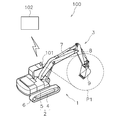
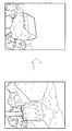
- FIG. 1 is a schematic diagram illustrating a classification system 100 according to the embodiment.
- the classification system 100 is a system for determining the work performed by the work vehicle 1.
- the work vehicle 1 is a hydraulic shovel.
- Work vehicle 1 includes vehicle body 2 and work implement 3.
- the vehicle body 2 includes the traveling unit 4 and the revolving unit 5.
- the traveling body 4 includes a crawler belt 6. When the crawler belt 6 is driven, the work vehicle 1 runs.
- the revolving unit 5 is attached to the traveling unit 4 so as to be revolvable.
- the work implement 3 is movably attached to the vehicle body 2. Specifically, the work machine 3 is rotatably attached to the swing body 5.
- Work implement 3 includes boom 7, arm 8, and bucket 9.
- the boom 7 is rotatably attached to the swing body 5.
- the arm 8 is rotatably attached to the boom 7.
- the bucket 9 is rotatably attached to the arm 8.
- the classification system 100 includes a camera 101 and a computer 102.
- the camera 101 is attached to the vehicle body 2. Specifically, the camera 101 is attached to the swing body 5.
- the camera 101 is arranged from the vehicle main body 2 to a working position P1 of the working machine 3. The direction of the camera 101 with respect to the vehicle body 2 is fixed.
- the work position P1 is a predetermined range including at least a part of the work machine 3 and its surroundings.
- the work position P1 includes the bucket 9 and its surroundings. Therefore, the image data includes an image of the operation of the bucket 9. Further, the image data includes an image of the background of the bucket 9.
- the working position P1 may further include at least a part of the arm 8.
- the camera 101 generates image data indicating a plurality of images of the work position P1 taken in chronological order. More specifically, the camera 101 generates moving image data of the work position P1.
- the computer 102 communicates with the camera 101 wirelessly or by wire.
- the camera 101 transmits image data to the computer 102.
- the computer 102 may receive image data from the camera 101 via a communication network.
- the computer 102 may receive image data from the camera 101 via a recording medium.
- the computer 102 may be arranged at a work site where the work vehicle 1 exists. Alternatively, the computer 102 may be located at a management center remote from the work site. The computer 102 may be specially designed for the classification system 100 or may be a general-purpose PC (Personal Computer). The computer 102 receives image data from the camera 101. The computer 102 determines the classification of the work of the work vehicle 1 from the image data by using the learned model of the artificial intelligence.
- PC Personal Computer
- FIG. 2 is a schematic diagram showing the configuration of the computer 102.
- the computer 102 includes a processor 103, a storage device 104, a communication interface 105, and an I / O interface 106.
- the processor 103 is, for example, a CPU (Central Processing Unit).
- the storage device 104 includes a medium that records information such as recorded programs and data so that the processor 103 can read the information.
- the storage device 104 includes a system memory such as a random access memory (RAM) or a read only memory (ROM), and an auxiliary storage device.
- the auxiliary storage device may be, for example, a magnetic recording medium such as a hard disk, an optical recording medium such as a CD or a DVD, or a semiconductor memory such as a flash memory.
- the storage device 104 may be built in the computer 102.
- the storage device 104 may include an external recording medium detachably connected to the computer 102.
- the communication interface 105 is, for example, a wired LAN (Local Area Network) module or a wireless LAN module, and is an interface for performing communication via a communication network.
- the I / O interface 106 is, for example, a USB (Universal Serial Bus) port or the like, and is an interface for connecting to an external device.
- the computer 102 is connected to the input device 107 and the output device 108 via the I / O interface 106.
- the input device 107 is a device for the user to input to the computer 102.
- the input device 107 includes, for example, a pointing device such as a mouse or a trackball.
- the input device 107 may include a device for character input such as a keyboard.
- the output device 108 includes, for example, a display.
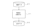
- FIG. 3 is a diagram showing a part of the configuration of the classification system 100.
- the classification system 100 includes a learned classification model 111.
- the learned classification model 111 is implemented in the computer 102.
- the learned classification model 111 may be stored in the storage device 104 of the computer 102.
- modules and models may be implemented in hardware, software executable on hardware, firmware, or a combination thereof.
- Modules and models may include programs, algorithms, and data executed by the processor.
- the functions of the modules and models may be performed by a single module, or may be performed separately among multiple modules.
- the modules and models may be distributed and arranged on a plurality of computers.
- the classification model 111 is an artificial intelligence model for image analysis. Specifically, the classification model 111 is an artificial intelligence model for moving image analysis. The classification model 111 analyzes the input image data D11 and outputs a classification corresponding to a moving image in the image data D11. The computer 102 determines the classification of the work of the work vehicle 1 by executing a moving image analysis on the image data D11 using the artificial intelligence classification model 111. The classification model 111 outputs output data D12 indicating the classification of the determined work.
- the classification model 111 includes the neural network 120 shown in FIG.
- the classification model 111 includes a deep neural network such as a convolutional neural network (CNN).
- CNN convolutional neural network
- the neural network 120 includes an input layer 121, a hidden layer 122 (hidden layer), and an output layer 123.
- Each layer 121, 122, 123 has one or more neurons.
- the number of neurons in the input layer 121 can be set according to the number of pixels of the image data D11.
- the number of neurons in the intermediate layer 122 can be set as appropriate.
- the output layer 123 can be set according to the number of work classifications of the work vehicle 1.
- ⁇ ⁇ ⁇ ⁇ ⁇ ⁇ Neurons in adjacent layers are connected to each other, and a weight (connection weight) is set for each connection.
- the number of neuron connections may be set as appropriate.
- a threshold is set for each neuron, and the output value of each neuron is determined by whether or not the sum of the product of the input value to each neuron and the weight exceeds the threshold.
- the image data D11 of the work vehicle 1 is input to the input layer 121.
- An output value indicating the probability of each classified operation is output to the output layer 123.
- the classification model 111 has been learned to output an output value indicating the probability of each classified work when the image data D11 is input.
- the learned parameters of the classification model 111 obtained by the learning are stored in the storage device 104.
- the learned parameters include, for example, the number of layers of the neural network 120, the number of neurons in each layer, the connection relationship between neurons, the weight of connection between neurons, and the threshold value of each neuron.
- FIG. 5 is a flowchart showing processing executed by the computer 102 (processor 103) to determine the work of the work vehicle 1.
- the computer 102 acquires image data D11 of the work vehicle 1 captured by the camera 101.
- the computer 102 may acquire the image data D11 captured by the camera 101 in real time.
- the computer 102 may acquire the image data D11 captured by the camera 101 at a predetermined time or at predetermined time intervals.
- the computer 102 stores the image data D11 in the storage device 104.
- step S102 the computer 102 executes a moving image analysis using the learned classification model 111.
- the computer 102 executes the image analysis based on the neural network 120 described above, using the moving image indicated by the image data D11 acquired in step S101 as input data to the classification model 111.
- the computer 102 inputs the pixel values included in the image data D11 to each neuron included in the input layer 121 of the neural network 120.
- the computer 102 obtains the probability of each classification of the work of the work vehicle 1 as output data D12.
- the work classification includes “digging”, “hoist turning”, “discharge”, and “empty turning”. Therefore, the computer 102 obtains an output value indicating the probability of each classification of “digging”, “hoist turning”, “discharge”, and “empty turning”.
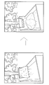
- FIG. 6 is a diagram illustrating an example of image data of “digging” captured by the camera 101.
- the excavation image data shows the motion of the bucket 9 rotating in the excavation direction until the bucket 9 comes into contact with the soil and then leaves.
- FIG. 7 is a diagram illustrating an example of image data of “hoist turning” captured by the camera 101.
- the image data of the hoist turning shows a moving image of the operation from when the background of the bucket 9 starts to change continuously due to the turning of the turning body 5 until the change stops.
- FIG. 8 is a diagram showing an example of image data of “discharge” taken by the camera 101.
- the image data of the earth discharging shows a moving image from the rotation of the bucket 9 in the earth discharging direction to the start of the opening of the bucket 9 until all the soil falls from the bucket 9.
- FIG. 9 is a diagram illustrating an example of image data of “empty turn” captured by the camera 101.
- the image data of the unloading turning shows a moving image of the operation from when the background of the bucket 9 starts to change continuously due to the turning of the turning body 5 until the change stops.
- the posture of the bucket 9 is different in the image data of the unloading turning than in the image data of the hoist turning.
- the ⁇ ⁇ ⁇ classification model 111 has been learned so that the output value of the “digging” classification is high for image data indicating digging as shown in FIG. 6.
- the classification model 111 has already been learned so that the output value of the classification “hoist rotation” is high for image data indicating a hoist rotation as shown in FIG.
- the classification model 111 has been learned so that the output value of the classification of “discharge” is high for image data indicating discharge as shown in FIG.
- the classification model 111 has been learned so that the output value of the classification of “empty turn” becomes higher for image data indicating an empty turn as shown in FIG.
- step S103 the computer 102 determines the classification of the work of the work vehicle 1.
- the computer 102 determines the classification of the work of the work vehicle 1 based on the probability of each classification indicated by the output data D12.
- the computer 102 determines the classification having the highest probability as the work of the work vehicle 1. Thereby, the computer 102 estimates the work performed by the work vehicle 1.
- step S104 the computer 102 records the work time of the work vehicle 1 in the category determined in step S103. For example, when the work vehicle 1 is excavating, the computer 102 determines the classification of the operation as “excavation” and records the excavation operation time.
- step S105 the computer 102 generates management data including the classification of work and the work time.
- the computer 102 records the management data in the storage device 104. Note that the processes in steps S101 to S105 described above may be executed in real time while the work vehicle 1 is working. Alternatively, the processing of steps S101 to S105 may be executed after the work of the work vehicle 1 is completed.
- image data is acquired from the camera 101 disposed on the vehicle body 2 toward the work position P1 by the work implement 3.
- the positional relationship between the work position P1 and the camera is fixed. Therefore, even if the direction of the work vehicle 1 changes, the positional relationship between the work position P1 in the moving image and the camera 101 does not change. Therefore, a learned model with high determination accuracy can be easily constructed. Thereby, the work by the work vehicle 1 can be easily and accurately determined using the artificial intelligence.
- the computer 102 can acquire the image data D11 obtained by photographing the work vehicle 1 from the camera 101 attached to the vehicle body 2 of the work vehicle 1, and determine the work of the work vehicle 1. Therefore, the work can be easily and accurately determined by attaching the camera 101 to the work vehicle 1 having no work determination equipment such as a specific sensor.
- the classification of the work is determined from the image of the work vehicle 1, and the work time of the classification is recorded as management data. Therefore, by taking images of the work vehicle 1 in time series, the computer 102 can easily and automatically perform a time study of work by the work vehicle 1. In addition, by capturing time-series images of the plurality of work vehicles 1 at the work site and generating management data by the classification system 100, the computer 102 can perform a time study of the work performed by the plurality of work vehicles 1 at the work site. It can be done easily and automatically.
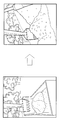
- FIG. 10 is a diagram showing a learning system 200 for learning the classification model 111.
- the learning system 200 is configured by a computer including a processor and a storage device, similarly to the computer 102 described above.
- the learning system 200 includes a learning data generation module 211 and a learning module 212.
- the learning data generation module 211 generates learning data D23 from the image data D21 and the work data D22 of the work vehicle 1.
- the image data D21 is obtained from the camera 101 attached to the vehicle body 2 in the same manner as the image data D11 described above.
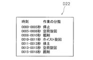
- FIG. 11 is a diagram showing an example of the work data D22.
- the work data D22 includes a time in an image in the image data D21 and a work classification assigned to each time.
- the assignment of the classification may be performed by a person.
- the learning system 200 has a classification model 111 for image analysis.
- the learning module 212 optimizes the parameters of the classification model 111 by learning the classification model 111 using the learning data D23.
- the learning system 200 acquires the optimized parameter as the learned parameter D24.
- the initial values of various parameters of the classification model 111 may be given by a template. Alternatively, the initial values of the parameters may be provided manually by human input.
- the learning system 200 may re-learn the classification model 111. When re-learning the classification model 111, the learning system 200 may prepare an initial value of the parameter based on the learned parameter D24 of the classification model 111 to be re-learned.
- the learning system 200 may update the learned parameter D24 by periodically executing the learning of the classification model 111 described above.
- the learning system 200 may transfer the updated learned parameter D24 to the computer 102 of the classification system 100.
- the computer 102 may update the parameters of the classification model 111 with the transferred learned parameters D24.
- the configuration of the classification system 100 and / or the learning system 200 may be changed.
- the classification system 100 may include a plurality of computers.
- the processing by the classification system 100 described above may be executed by being distributed to a plurality of computers.
- the learning system 200 may include a plurality of computers.
- the processing by the learning system 200 described above may be executed in a distributed manner by a plurality of computers.
- the generation of the learning data and the learning of the classification model 111 may be executed by different computers. That is, the learning data generation module 211 and the learning module 212 may be implemented on different computers.
- Computer 102 may include multiple processors. At least a part of the processing described above is not limited to the CPU, and may be executed by another processor such as a GPU (Graphics Processing Unit). The above-described processing may be executed by being distributed to a plurality of processors.
- processors such as a GPU (Graphics Processing Unit).
- the above-described processing may be executed by being distributed to a plurality of processors.
- the classification model 111 includes the neural network 120.
- the classification model 111 is not limited to a neural network, and may be a model that can perform image analysis with high accuracy, such as a support vector machine.
- the work vehicle 1 is not limited to the hydraulic excavator, and may be another vehicle such as a bulldozer, a wheel loader, a grader, or a dump truck.
- the classification system 100 may determine the work of a plurality of work vehicles.
- the classification model 111, the learned parameter D24, and / or the learning data D23 may be prepared for each type of the work vehicle 1.
- the classification model 111, the learned parameter D24, and / or the learning data D23 may be common to a plurality of types of work vehicles 1. In that case, the classification model 111 may estimate the type of the work vehicle 1 together with the work of the work vehicle 1.
- the classification system 100 may include a plurality of cameras 101.
- the plurality of cameras 101 may capture images of the plurality of work vehicles 1.
- the computer 102 may receive the image data D11 from each of the plurality of cameras 101.
- the camera 101 may acquire a time-series still image. That is, the image data D11 may be data indicating a plurality of time-series still images.
- a part of the work classification may be changed or omitted.
- the work classification may further include other classifications.
- the classification of the work may include a classification such as “loading” or “groove excavation”.
- the operation of the work machine 3 is similar between “loading” and “groove excavation”. Therefore, it is difficult to determine the work with high accuracy by the above-described determination using the sensor.
- the work can be accurately determined.
- a part of the above-described processing may be omitted or changed.
- the process of recording the work time may be omitted.
- the process of generating management data may be omitted.
- the classification model 111 described above is not limited to a model learned by machine learning using learning data, and may be a model generated using the learned model.
- the classification model 111 may be another learned model (derived model) in which the parameter is changed by further learning the learned model using new data to further improve the accuracy.
- the classification model 111 may be another learned model (distillation model) obtained by learning based on a result obtained by repeatedly inputting and outputting data to and from the learned model.
- the work by the work vehicle can be easily and accurately determined using the artificial intelligence.
Landscapes
- Engineering & Computer Science (AREA)
- Theoretical Computer Science (AREA)
- Physics & Mathematics (AREA)
- General Physics & Mathematics (AREA)
- Evolutionary Computation (AREA)
- General Engineering & Computer Science (AREA)
- Software Systems (AREA)
- General Health & Medical Sciences (AREA)
- Computing Systems (AREA)
- Health & Medical Sciences (AREA)
- Artificial Intelligence (AREA)
- Multimedia (AREA)
- Computer Vision & Pattern Recognition (AREA)
- Structural Engineering (AREA)
- Civil Engineering (AREA)
- Mining & Mineral Resources (AREA)
- Databases & Information Systems (AREA)
- Medical Informatics (AREA)
- Molecular Biology (AREA)
- Biomedical Technology (AREA)
- Biophysics (AREA)
- Computational Linguistics (AREA)
- Data Mining & Analysis (AREA)
- Life Sciences & Earth Sciences (AREA)
- Mathematical Physics (AREA)
- Mechanical Engineering (AREA)
- Quality & Reliability (AREA)
- Image Analysis (AREA)
- Operation Control Of Excavators (AREA)
- Time Recorders, Dirve Recorders, Access Control (AREA)
Abstract
システムは、カメラとプロセッサとを備える。カメラは、車両本体に取り付けられ、車両本体から作業機による作業位置に向けて配置される。カメラは、作業位置を時系列で撮影した画像を示す画像データを生成する。プロセッサは、学習済みモデルを有する。学習済みモデルは、画像データを入力データとして、画像データに対応する作業の分類を出力する。プロセッサは、画像データを取得し、学習済みモデルを用いた画像解析により、画像データから作業の分類を決定する。
Description
本発明は、作業車両による作業を判定するためのシステム、方法、及び学習済みモデルの製造方法に関する。
従来、作業車両による作業をコンピュータによって推定する技術が知られている。例えば、油圧ショベルは、掘削、旋回、或いは排土などの動作を行う。特許文献1では、油圧ショベルのこれらの作業を、油圧ショベルに備えられたセンサからの検出値に基づいて、コントローラが判定している。例えば、油圧ショベルは、回転速度センサ、圧力センサ、及び複数の角度センサを備えている。回転速度センサは、エンジンの回転速度を検出する。圧力センサは、油圧ポンプの吐出圧を検出する。複数の角度センサは、ブーム角度、アーム角度、及びバケット角度を検出する。コントローラは、これらのセンサからの検出値に基づいて、油圧ショベルが実行している作業を判定する。
しかし、上記の技術では、センサを備えていない作業車両の作業を判定することはできない。また、作業現場に配置された複数の作業車両を管理するために各作業車両の動作を判定する場合、全ての作業車両が、作業の判定に必要なセンサを備えているとは限らない。従って、作業現場に配置された複数の作業車両を管理するために各作業車両の作業を判定することは容易ではない。
一方、近年、人や物の動作を撮影した動画を人工知能によって解析することで、どのような動作が行われているかをコンピュータが判定する技術が研究されている。例えば、動画を扱う人工知能のモデルとして、再帰型ニューラルネットワーク(RNN)などが研究されている。このような人工知能技術を用いて、作業車両の動作を撮影した動画を解析することができれば、作業車両の作業をコンピュータによって判定することができる。
しかし、作業車両の外部に配置されたカメラにより作業車両を撮影する場合、同じ作業であっても、作業車両の向きに応じて、取得される動画は異なるものとなる。従って、人工知能のモデルを学習させるためには、作業車両の向きを変化させた膨大な量の動画が必要となる。そのため、判定精度の高い学習済みモデルを構築することは容易ではない。
本発明の目的は、人工知能を用いて作業車両による作業を容易、且つ、精度良く判定することにある。
第1の態様は、作業車両が実行している作業を判定するためのシステムである。作業車両は、車両本体と、車両本体に対して可動的に取り付けられた作業機と、を含む。本態様に係るシステムは、カメラとプロセッサとを備える。カメラは、車両本体に取り付けられ、車両本体から作業機による作業位置に向けて配置される。カメラは、作業位置を時系列で撮影した画像を示す画像データを生成する。プロセッサは、学習済みモデルを有する。学習済みモデルは、画像データを入力データとして、画像データに対応する作業の分類を出力する。プロセッサは、画像データを取得し、学習済みモデルを用いた画像解析により、画像データから作業の分類を決定する。
第2の態様は、作業車両が実行している作業を判定するために、コンピュータによって実行される方法である。作業車両は、車両本体と、車両本体に対して可動的に取り付けられた作業機と、を含む。本態様に係る方法は、以下の処理を備える。第1の処理は、作業機による作業位置に向けて車両本体において固定的に配置されたカメラから、作業位置を時系列で撮影した画像を示す画像データを取得することである。第2の処理は、学習済みモデルを用いた画像解析により、画像データから作業の分類を決定することである。学習済みモデルは、画像データを入力データとして、画像データに対応する作業の分類を出力する。
第3の態様は、作業車両が実行している作業を判定するための学習済みモデルの製造方法である。作業車両は、車両本体と、車両本体に対して可動的に取り付けられた作業機と、を含む。本態様に係る学習済みモデルの製造方法は、以下の処理を備える。第1の処理は、車両本体から作業機による作業位置に向けて作業位置を時系列で撮影した画像を示す画像データを取得することである。第2の処理は、画像における時刻と、時刻ごとに割り当てられた作業の分類とを含む作業データを生成することである。第3の処理は、画像データと作業データとを学習データとして、画像解析のためのモデルを学習させることで、学習済みモデルを構築することである。
本発明では、作業機による作業位置に向けて車両本体に配置されたカメラから画像データが取得される。従って、作業車両の向きが変化しても、画像中の作業位置とカメラとの位置関係の変化は少ない。そのため、判定精度の高い学習済みモデルを容易に構築することができる。それにより、人工知能を用いて作業車両による作業を容易、且つ、精度良く判定することができる。
以下、図面を参照して実施形態について説明する。図1は、実施形態に係る分類システム100を示す模式図である。分類システム100は、作業車両1が行っている作業を判定するためのシステムである。本実施形態において、作業車両1は、油圧ショベルである。作業車両1は、車両本体2と作業機3とを含む。
車両本体2は、走行体4と旋回体5とを含む。走行体4は、履帯6を含む。履帯6が駆動されることで、作業車両1は走行する。旋回体5は、走行体4に対して旋回可能に取り付けられている。作業機3は、車両本体2に対して可動的に取り付けられている。詳細には、作業機3は、旋回体5に対して回転可能に取り付けられている。作業機3は、ブーム7と、アーム8と、バケット9とを含む。ブーム7は、旋回体5に対して回転可能に取り付けられている。アーム8は、ブーム7に対して回転可能に取り付けられている。バケット9は、アーム8に対して回転可能に取り付けられている。
分類システム100は、カメラ101とコンピュータ102とを含む。カメラ101は、車両本体2に取り付けられている。詳細には、カメラ101は、旋回体5に取り付けられている。カメラ101は、車両本体2から作業機3による作業位置P1に向けて配置されている。車両本体2に対するカメラ101の向きは固定されている。作業位置P1は、作業機3の少なくとも一部、及び、その周囲を含む所定範囲である。
詳細には、作業位置P1は、バケット9、及び、その周囲を含む。従って、画像データは、バケット9の動作の映像を含む。また、画像データは、バケット9の背景の映像を含む。作業位置P1は、アーム8の少なくとも一部をさらに含んでもよい。カメラ101は、作業位置P1を時系列で撮影した複数の画像を示す画像データを生成する。詳細には、カメラ101は、作業位置P1を撮影した動画データを生成する。
コンピュータ102は、カメラ101と無線、或いは有線により通信を行う。カメラ101は、画像データをコンピュータ102に送信する。コンピュータ102は、通信ネットワークを介して、カメラ101から画像データを受信してもよい。コンピュータ102は、記録媒体を介してカメラ101から画像データを受信してもよい。
コンピュータ102は、作業車両1が存在する作業現場に配置されてもよい。或いは、コンピュータ102は、作業現場から離れた管理センターに配置されてもよい。コンピュータ102は、分類システム100用に専用に設計されたものであってもよく、或いは汎用のPC(Personal Computer)であってもよい。コンピュータ102は、カメラ101から画像データを受信する。コンピュータ102は、人工知能の学習済みモデルを用いることで、画像データから作業車両1の作業の分類を決定する。
図2は、コンピュータ102の構成を示す模式図である。図2に示すように、コンピュータ102は、プロセッサ103と、記憶装置104と、通信インタフェース105と、I/Oインタフェース106とを含む。プロセッサ103は、例えばCPU(Central Processing Unit)である。記憶装置104は、記録されたプログラム及びデータなどの情報をプロセッサ103が読み取り可能なように記録する媒体を含む。記憶装置104は、RAM(Random Access Memory)、或いはROM(Read Only Memory)などのシステムメモリと、補助記憶装置とを含む。補助記憶装置は、例えばハードディスク等の磁気的記録媒体、CD、DVD等の光学的記録媒体、或いは、フラッシュメモリ等の半導体メモリであってもよい。記憶装置104は、コンピュータ102に内蔵されてもよい。記憶装置104は、コンピュータ102に着脱可能に接続される外部記録媒体を含んでもよい。
通信インタフェース105は、例えば有線LAN(Local Area Network)モジュール、或いは無線LANモジュール等であり、通信ネットワークを介した通信を行うためのインタフェースである。I/Oインタフェース106は、例えばUSB(Universal Serial Bus)ポート等であり、外部装置と接続するためのインタフェースである。
コンピュータ102は、I/Oインタフェース106を介して、入力装置107、及び出力装置108と接続される。入力装置107は、ユーザーがコンピュータ102への入力を行うための装置である。入力装置107は、例えば、マウス、或いはトラックボール等のポインティングデバイスを含む。入力装置107は、キーボード等の文字入力のための装置を含んでもよい。出力装置108は、例えば、ディスプレイを含む。
図3は、分類システム100の構成の一部を示す図である。図3に示すように、分類システム100は、学習済みの分類モデル111を含む。学習済みの分類モデル111は、コンピュータ102に実装されている。学習済みの分類モデル111は、コンピュータ102の記憶装置104に保存されていてもよい。
本実施形態において、モジュール及びモデルは、ハードウェア、ハードウェア上で実行可能なソフトウェア、ファームウェア、或いはそれらの組合せに実装されていてもよい。モジュール及びモデルは、プロセッサによって実行されるプログラム、アルゴリズム、及びデータを含んでもよい。モジュール及びモデルの機能は、単一のモジュールによって実行されてもよく、或いは複数のモジュールに分散して実行されてもよい。モジュール及びモデルは、複数のコンピュータに分散して配置されてもよい。
分類モデル111は、画像解析のための人工知能モデルである。詳細には、分類モデル111は、動画解析のための人工知能モデルである。分類モデル111は、入力された画像データD11を解析して、画像データD11中の動画に対応する分類を出力する。コンピュータ102は、画像データD11に対して、人工知能の分類モデル111を用いた動画解析を実行することにより、作業車両1の作業の分類を決定する。分類モデル111は、決定した作業の分類を示す出力データD12を出力する。
分類モデル111は、図4に示すニューラルネットワーク120を含む。例えば、分類モデル111は、畳み込みニューラルネットワーク(CNN)などのディープニューラルネットワークを含む。
図4に示すように、ニューラルネットワーク120は、入力層121、中間層122(隠れ層)、及び出力層123を含む。各層121,122,123は、1又は複数のニューロンを備えている。例えば、入力層121のニューロンの数は、画像データD11の画素数に応じて設定することができる。中間層122のニューロンの数は、適宜設定することができる。出力層123は、作業車両1の作業の分類数に応じて設定することができる。
互いに隣接する層のニューロン同士は結合されており、各結合には重み(結合荷重)が設定されている。ニューロンの結合数は、適宜設定されてよい。各ニューロンには閾値が設定されており、各ニューロンへの入力値と重みとの積の和が閾値を超えているか否かによって各ニューロンの出力値が決定される。
入力層121には、作業車両1の画像データD11が入力される。出力層123には、分類された各動作の確率を示す出力値が出力される。分類モデル111は、画像データD11が入力されると、分類された各作業の確率を示す出力値を出力するように学習済みである。学習によって得られた分類モデル111の学習済みパラメータは、記憶装置104に記憶されている。学習済みパラメータは、例えば、ニューラルネットワーク120の層数、各層におけるニューロンの個数、ニューロン同士の結合関係、各ニューロン間の結合の重み、及び各ニューロンの閾値を含む。
図5は、作業車両1の作業を判定するためにコンピュータ102(プロセッサ103)によって実行される処理を示すフローチャートである。図5に示すように、ステップS101では、コンピュータ102は、カメラ101が撮影した作業車両1の画像データD11を取得する。コンピュータ102は、カメラ101が撮影した画像データD11をリアルタイムに取得してもよい。或いは、コンピュータ102は、カメラ101が撮影した画像データD11を所定時刻に、或いは所定時間ごとに取得してもよい。コンピュータ102は、画像データD11を記憶装置104に保存する。
ステップS102では、コンピュータ102は、学習済みの分類モデル111を用いた動画解析を実行する。コンピュータ102は、ステップS101で取得した画像データD11が示す動画を、分類モデル111への入力データとして用いて、上述したニューラルネットワーク120に基づく画像解析を実行する。
例えば、コンピュータ102は、画像データD11に含まれる画素値をニューラルネットワーク120の入力層121に含まれる各ニューロンに入力する。コンピュータ102は、作業車両1の作業の各分類の確率を出力データD12として得る。本実施形態において、作業の分類は、「掘削」、「ホイスト旋回」、「排土」、及び「空荷旋回」を含む。従って、コンピュータ102は、「掘削」、「ホイスト旋回」、「排土」、及び「空荷旋回」の各分類の確率を示す出力値を得る。
図6は、カメラ101が撮影した「掘削」の画像データの一例を示す図である。図6に示すように、掘削の画像データは、バケット9が掘削方向に回転し、バケット9が土に接触してから離れるまでの動作を動画で示す。図7は、カメラ101が撮影した「ホイスト旋回」の画像データの一例を示す図である。図7に示すように、ホイスト旋回の画像データは、旋回体5の旋回により、バケット9の背景が連続的に変化し始めてから、変化が止まるまでの動作を動画で示す。
図8は、カメラ101が撮影した「排土」の画像データの一例を示す図である。図8に示すように、排土の画像データは、バケット9が排土方向に回転して、バケット9が開き始めてから、バケット9から土が全て落ちるまでの動作を動画で示す。図9は、カメラ101が撮影した「空荷旋回」の画像データの一例を示す図である。図9に示すように、空荷旋回の画像データは、旋回体5の旋回により、バケット9の背景が連続的に変化し始めてから、変化が止まるまでの動作を動画で示す。ただし、空荷旋回の画像データでは、ホイスト旋回の画像データと比べて、バケット9の姿勢が異なる。
分類モデル111は、図6に示すような掘削を示す画像データに対しては「掘削」の分類の出力値が高くなるように、学習済みである。分類モデル111は、図7に示すようなホイスト旋回を示す画像データに対しては「ホイスト旋回」の分類の出力値が高くなるように、学習済みである。分類モデル111は、図8に示すような排土を示す画像データに対しては「排土」の分類の出力値が高くなるように、学習済みである。分類モデル111は、図9に示すような空荷旋回を示す画像データに対しては「空荷旋回」の分類の出力値が高くなるように、学習済みである。
ステップS103では、コンピュータ102は、作業車両1の作業の分類を決定する。コンピュータ102は、出力データD12が示す各分類の確率に基づいて、作業車両1の作業の分類を決定する。コンピュータ102は、最も高い確率を有する分類を、作業車両1の作業として決定する。これにより、コンピュータ102は、作業車両1が実行している作業を推定する。
ステップS104では、コンピュータ102は、ステップS103で決定された分類での作業車両1の作業時間を記録する。例えば、作業車両1が掘削を行っているときには、コンピュータ102は、作業の分類を「掘削」に決定すると共に、掘削の作業時間を記録する。
ステップS105では、コンピュータ102は、作業の分類及び作業時間を含む管理データを生成する。コンピュータ102は、管理データを記憶装置104に記録する。なお、上述したステップS101からS105の処理は、それぞれ作業車両1の作業中にリアルタイムに実行されてもよい。或いは、ステップS101からS105の処理は、作業車両1の作業終了後に実行されてもよい。
以上説明した本実施形態に係る分類システム100では、作業機3による作業位置P1に向けて車両本体2に配置されたカメラ101から画像データが取得される。作業位置P1とカメラとの位置関係とは固定されている。従って、作業車両1の向きが変化しても、動画中の作業位置P1とカメラ101との位置関係は変化しない。そのため、判定精度の高い学習済みモデルを容易に構築することができる。それにより、人工知能を用いて作業車両1による作業を容易、且つ、精度良く判定することができる。
分類システム100では、コンピュータ102は、作業車両1の車両本体2に取り付けられたカメラ101から作業車両1を撮影した画像データD11を取得して、作業車両1の作業を判定することができる。従って、特定のセンサなどの作業判定用の装備を備えていない作業車両1に対しても、カメラ101を取り付けることで、容易、且つ、精度良く作業を判定することができる。
分類システム100では、作業車両1の画像から、作業の分類を決定すると共に、当該分類の作業時間が管理データとして記録される。従って、作業車両1の画像を時系列で撮影することで、作業車両1による作業のタイムスタディをコンピュータ102によって容易且つ自動で行うことができる。また、作業現場における複数の作業車両1の時系列の画像をそれぞれ撮影して、分類システム100によって管理データを生成することで、作業現場における複数の作業車両1による作業のタイムスタディをコンピュータ102によって容易且つ自動で行うことができる。
次に、実施形態に係る分類モデル111の学習方法について説明する。図10は、分類モデル111の学習を行う学習システム200を示す図である。学習システム200は、上述したコンピュータ102と同様にプロセッサと記憶装置とを含むコンピュータによって構成される。
学習システム200は、学習データ生成モジュール211と学習モジュール212とを含む。学習データ生成モジュール211は、作業車両1の画像データD21と作業データD22とから学習データD23を生成する。画像データD21は、上述した画像データD11と同様に、車両本体2に取り付けられたカメラ101から取得される。
図11は、作業データD22の一例を示す図である。図11に示すように、作業データD22は、画像データD21中の画像における時刻と、当該時刻ごとに割り当てられた作業の分類とを含む。分類の割り当ては、人によって行われてもよい。
学習システム200には、画像解析のための分類モデル111が用意されている。学習モジュール212は、学習データD23によって分類モデル111を学習させることで、分類モデル111のパラメータを最適化する。学習システム200は、最適化されたパラメータを学習済みパラメータD24として取得する。
なお、分類モデル111の各種のパラメータの初期値は、テンプレートにより与えられてもよい。或いは、パラメータの初期値は、人間の入力により手動で与えられてもよい。学習システム200は、分類モデル111の再学習を行ってもよい。分類モデル111の再学習を行うときには、学習システム200は、再学習を行う対象となる分類モデル111の学習済みパラメータD24に基づいて、パラメータの初期値を用意してもよい。
学習システム200は、上述した分類モデル111の学習を定期的に実行することで、学習済みパラメータD24を更新してもよい。学習システム200は、更新した学習済みパラメータD24を分類システム100のコンピュータ102に転送してもよい。コンピュータ102は、転送された学習済みパラメータD24によって、分類モデル111のパラメータを更新してもよい。
以上、本発明の一実施形態について説明したが、本発明は上記実施形態に限定されるものではなく、発明の要旨を逸脱しない範囲で種々の変更が可能である。
分類システム100、及び/又は、学習システム200の構成が変更されてもよい。例えば、分類システム100は、複数のコンピュータを含んでもよい。上述した分類システム100による処理は、複数のコンピュータに分散して実行されてもよい。
学習システム200は、複数のコンピュータを含んでもよい。上述した学習システム200による処理は、複数のコンピュータで分散して実行されてもよい。例えば、学習データの生成と、分類モデル111の学習とは、異なるコンピュータによって実行されてもよい。すなわち、学習データ生成モジュール211と学習モジュール212とは異なるコンピュータに実装されてもよい。
コンピュータ102は、複数のプロセッサを含んでもよい。上述した処理の少なくとも一部は、CPUに限らず、GPU(Graphics Processing Unit)などの他のプロセッサによって実行されてもよい。上述した処理は、複数のプロセッサに分散して実行されてもよい。
上記実施形態では、分類モデル111はニューラルネットワーク120を含む。しかし、分類モデル111は、ニューラルネットワークに限らず、例えば、サポートベクターマシンなど、画像解析を精度良く行えるモデルあってもよい。
作業車両1は、油圧ショベルに限らず、ブルドーザ、ホイールローダ、グレーダー、或いはダンプトラックなどの他の車両であってもよい。分類システム100は、複数の作業車両の作業を判定してもよい。分類モデル111、学習済みパラメータD24、及び/又は、学習データD23は、作業車両1の種類ごとに用意されてもよい。或いは、分類モデル111、学習済みパラメータD24、及び/又は、学習データD23は、複数種類の作業車両1に共通であってもよい。その場合、分類モデル111は、作業車両1の作業と共に作業車両1の種類を推定してもよい。
分類システム100は、カメラ101を複数有してもよい。複数のカメラ101は、複数の作業車両1の画像を撮影してもよい。コンピュータ102は、複数のカメラ101のそれぞれから、画像データD11を受信してもよい。カメラ101は、時系列の静止画像を取得してもよい。すなわち、画像データD11は、時系列の複数の静止画像を示すデータであってもよい。
作業の分類の一部が変更、或いは省略されてもよい。或いは、作業の分類は、他の分類をさらに含んでもよい。例えば、作業の分類は、「積込」或いは「溝掘削」などの分類を含んでもよい。「積込」と「溝掘削」とでは、作業機3の動作は類似している。そのため、上述したセンサによる判定では、精度良く作業を判定することは困難である。しかし、作業機3の背景を含む画像データから分類モデル111によって作業を判定することで、精度良く作業を判定することができる。
上述した処理の一部が省略、或いは変更されてもよい。例えば、作業時間を記録する処理が省略されてもよい。管理データを生成する処理が省略されてもよい。
上述した分類モデル111は、学習データを用いて機械学習により学習したモデルに限らず、当該学習したモデルを利用して生成されたモデルであってもよい。例えば、分類モデル111は、学習済みモデルに新たなデータを用いて更に学習させることで、パラメータを変化させ、精度をさらに高めた別の学習済みモデル(派生モデル)であってもよい。或いは、分類モデル111は、学習済みモデルにデータの入出力を繰り返すことで得られる結果を基に学習させた別の学習済みモデル(蒸留モデル)であってもよい。
本発明によれば、人工知能を用いて作業車両による作業を容易、且つ、精度良く判定することができる。
2 車両本体
3 作業機
4 走行体
5 旋回体
8 アーム
9 バケット
100 分類システム
101 カメラ
103 プロセッサ
P1 作業位置
3 作業機
4 走行体
5 旋回体
8 アーム
9 バケット
100 分類システム
101 カメラ
103 プロセッサ
P1 作業位置
Claims (15)
- 車両本体と、前記車両本体に対して可動的に取り付けられた作業機と、を含む作業車両が実行している作業を判定するためのシステムであって、
前記車両本体に取り付けられ、前記車両本体から前記作業機による作業位置に向けて配置され、前記作業位置を時系列で撮影した画像を示す画像データを生成するカメラと、
前記画像データを入力データとして、前記画像データに対応する前記作業の分類を出力する学習済みモデルを有するプロセッサと、
を備え、
前記プロセッサは、
前記画像データを取得し、
前記学習済みモデルを用いた画像解析により、前記画像データから前記作業の分類を決定する、
システム。 - 前記作業機は、アームと、前記アームに対して回転可能に取り付けられたバケットとを含み、
前記画像データは、前記バケットの動作の映像を含む、
請求項1に記載のシステム。 - 前記作業の分類は、掘削を含む、
請求項2に記載のシステム。 - 前記作業の分類は、排土を含む、
請求項2又は3に記載のシステム。 - 前記車両本体は、走行体と、前記走行体に対して旋回可能に取り付けられた旋回体とを含み、
前記カメラは、前記旋回体に取り付けられており、
前記画像データは、前記バケットと、前記旋回体の旋回によって変化する前記バケットの背景の映像を含む、
請求項1から4のいずれかに記載のシステム。 - 前記作業の分類は、ホイスト旋回を含む、
請求項5に記載のシステム。 - 前記作業の分類は、空荷旋回を含む、
請求項5又は6に記載のシステム。 - 前記画像データは、前記作業位置を撮影した動画を示す、
請求項1から7のいずれかに記載のシステム。 - 車両本体と、前記車両本体に対して可動的に取り付けられた作業機と、を含む作業車両が実行している作業を判定するために、コンピュータによって実行される方法であって、
前記作業機による作業位置に向けて前記車両本体において固定的に配置されたカメラから、前記作業位置を時系列で撮影した画像を示す画像データを取得することと、
前記画像データを入力データとして、前記画像データに対応する前記作業の分類を出力する学習済みモデルを用いた画像解析により、前記画像データから前記作業の分類を決定すること、
を備える方法。 - 前記作業機は、アームと、前記アームに対して回転可能に取り付けられたバケットとを含み、
前記画像データは、前記バケットの動作の映像を含む、
請求項9に記載の方法。 - 前記作業の分類は、掘削を含む、
請求項10に記載の方法。 - 前記作業の分類は、排土を含む、
請求項10又は11に記載の方法。 - 前記車両本体は、走行体と、前記走行体に対して旋回可能に取り付けられた旋回体とを含み、
前記カメラは、前記旋回体に取り付けられており、
前記画像データは、前記バケットと、前記旋回体の旋回によって変化する前記バケットの背景の映像を含む、
請求項9から12のいずれかに記載の方法。 - 前記作業の分類は、ホイスト旋回を含む、
請求項13に記載の方法。 - 車両本体と、前記車両本体に対して可動的に取り付けられた作業機と、を含む作業車両が実行している作業を判定するための学習済みモデルの製造方法であって、
前記車両本体から前記作業機による作業位置に向けて前記作業位置を時系列で撮影した画像を示す画像データを取得することと、
前記画像における時刻と、前記時刻ごとに割り当てられた前記作業の分類とを含む作業データを生成することと、
前記画像データと前記作業データとを学習データとして、画像解析のためのモデルを学習させることで、前記学習済みモデルを構築すること、
を備える学習済みモデルの製造方法。
Priority Applications (3)
| Application Number | Priority Date | Filing Date | Title |
|---|---|---|---|
| DE112019000630.4T DE112019000630T5 (de) | 2018-06-28 | 2019-03-19 | System und Verfahren zur Bestimmung von Arbeit eines Arbeitsfahrzeugs und Verfahren zum Erzeugen eines eingelernten Modells |
| CN201980010476.4A CN111656412B (zh) | 2018-06-28 | 2019-03-19 | 用于判定作业车辆所进行的作业的系统、方法以及已学习模型的制造方法 |
| US16/967,012 US20210040713A1 (en) | 2018-06-28 | 2019-03-19 | System and method for determining work of work vehicle, and method for producing trained model |
Applications Claiming Priority (2)
| Application Number | Priority Date | Filing Date | Title |
|---|---|---|---|
| JP2018123196A JP7166088B2 (ja) | 2018-06-28 | 2018-06-28 | 作業車両による作業を判定するためのシステム、方法、及び学習済みモデルの製造方法 |
| JP2018-123196 | 2018-06-28 |
Publications (1)
| Publication Number | Publication Date |
|---|---|
| WO2020003650A1 true WO2020003650A1 (ja) | 2020-01-02 |
Family
ID=68986940
Family Applications (1)
| Application Number | Title | Priority Date | Filing Date |
|---|---|---|---|
| PCT/JP2019/011521 Ceased WO2020003650A1 (ja) | 2018-06-28 | 2019-03-19 | 作業車両による作業を判定するためのシステム、方法、及び学習済みモデルの製造方法 |
Country Status (5)
| Country | Link |
|---|---|
| US (1) | US20210040713A1 (ja) |
| JP (1) | JP7166088B2 (ja) |
| CN (1) | CN111656412B (ja) |
| DE (1) | DE112019000630T5 (ja) |
| WO (1) | WO2020003650A1 (ja) |
Cited By (1)
| Publication number | Priority date | Publication date | Assignee | Title |
|---|---|---|---|---|
| CN115034309A (zh) * | 2022-06-14 | 2022-09-09 | 哈尔滨工业大学 | 基于支持向量机截面形状分类的回转装备同轴度测量方法 |
Families Citing this family (15)
| Publication number | Priority date | Publication date | Assignee | Title |
|---|---|---|---|---|
| JP7166108B2 (ja) * | 2018-08-31 | 2022-11-07 | 株式会社小松製作所 | 画像処理システム、表示装置、画像処理方法、学習済みモデルの生成方法、および学習用データセット |
| US11384508B2 (en) * | 2019-02-12 | 2022-07-12 | Caterpillar Inc. | Automated machine impeller clutch |
| US12006664B2 (en) * | 2019-05-24 | 2024-06-11 | Kawasaki Jukogyo Kabushiki Kaisha | Construction machinery with learning function |
| JP7583526B2 (ja) * | 2020-02-10 | 2024-11-14 | キヤノン株式会社 | 画像処理装置およびその制御方法ならびにプログラム |
| US11718972B2 (en) * | 2020-06-03 | 2023-08-08 | Deere & Company | Image-based attachment identification and position detection |
| US12024173B2 (en) * | 2020-11-04 | 2024-07-02 | Deere & Company | System and method for work state estimation and control of self-propelled work vehicles |
| US20220147933A1 (en) * | 2020-11-06 | 2022-05-12 | Moovila, Inc. | Systems and methods for characterizing work by working eqiupment based on proximity to a worker's computing device |
| JP7455732B2 (ja) * | 2020-11-17 | 2024-03-26 | 鹿島建設株式会社 | 土の評価システム、土の評価方法及び盛土の施工方法 |
| JP7594429B2 (ja) * | 2020-12-21 | 2024-12-04 | 株式会社クボタ | 作業推定モデル |
| IT202100000242A1 (it) * | 2021-01-07 | 2022-07-07 | Cnh Ind Italia Spa | Metodo per rilevare una missione di un veicolo da lavoro o agricolo attraverso una rete neurale e un'unità di controllo che implementa il metodo |
| US20230272599A1 (en) * | 2022-02-28 | 2023-08-31 | Caterpillar Inc. | Work machine safety zone control |
| US12325982B2 (en) * | 2022-11-02 | 2025-06-10 | Trimble Inc. | Construction site orchestration using dynamic computer vision |
| US12548136B2 (en) | 2022-11-15 | 2026-02-10 | Motion Metrics International Corp. | Monitoring an operating cycle of heavy equipment |
| US20240273954A1 (en) * | 2023-02-10 | 2024-08-15 | Deere & Company | Selective capture of work machine productivity factors based on work state estimation |
| IT202300016920A1 (it) | 2023-08-07 | 2025-02-07 | Cnh Ind Italia Spa | Sistema di visione ambientale e veicolo agricolo o da lavoro comprendente il sistema |
Citations (3)
| Publication number | Priority date | Publication date | Assignee | Title |
|---|---|---|---|---|
| JPH1060948A (ja) * | 1996-08-21 | 1998-03-03 | Yutani Heavy Ind Ltd | 油圧ショベル |
| JP2015217486A (ja) * | 2014-05-19 | 2015-12-07 | 富士通株式会社 | 判定装置、判定方法、および判定プログラム |
| JP2017142735A (ja) * | 2016-02-12 | 2017-08-17 | マツダ株式会社 | 車両用の歩行者動作識別装置 |
Family Cites Families (18)
| Publication number | Priority date | Publication date | Assignee | Title |
|---|---|---|---|---|
| US5999872A (en) * | 1996-02-15 | 1999-12-07 | Kabushiki Kaisha Kobe Seiko Sho | Control apparatus for hydraulic excavator |
| US7487066B2 (en) * | 2005-04-28 | 2009-02-03 | Caterpillar Inc. | Classifying a work machine operation |
| JP4746000B2 (ja) * | 2007-03-27 | 2011-08-10 | 株式会社小松製作所 | 建設機械の省燃費運転支援方法および省燃費運転支援システム |
| JP6232494B2 (ja) * | 2014-04-23 | 2017-11-15 | 株式会社日立製作所 | 掘削装置 |
| JP2015224875A (ja) * | 2014-05-26 | 2015-12-14 | Kyb株式会社 | 作業機の作動状態検出システム及び作業機 |
| US10032117B2 (en) * | 2014-09-17 | 2018-07-24 | Caterpillar Inc. | Method for developing machine operation classifier using machine learning |
| US20160312432A1 (en) * | 2015-04-23 | 2016-10-27 | Caterpillar Inc. | Computer Vision Assisted Work Tool Recognition and Installation |
| EP3399110B1 (en) * | 2015-12-28 | 2021-02-17 | Sumitomo (S.H.I.) Construction Machinery Co., Ltd. | Excavator |
| CN107704924B (zh) * | 2016-07-27 | 2020-05-19 | 中国科学院自动化研究所 | 同步自适应时空特征表达学习模型的构建方法及相关方法 |
| US10634492B2 (en) * | 2016-08-31 | 2020-04-28 | Deere & Company | Methods and apparatus to track a blade |
| JP6549545B2 (ja) * | 2016-10-11 | 2019-07-24 | ファナック株式会社 | 人の行動を学習してロボットを制御する制御装置およびロボットシステム |
| US10163033B2 (en) * | 2016-12-13 | 2018-12-25 | Caterpillar Inc. | Vehicle classification and vehicle pose estimation |
| CN106426186B (zh) * | 2016-12-14 | 2019-02-12 | 国网江苏省电力公司常州供电公司 | 一种基于多传感器信息融合的带电作业机器人自主作业方法 |
| US10011976B1 (en) * | 2017-01-03 | 2018-07-03 | Caterpillar Inc. | System and method for work tool recognition |
| US11549239B2 (en) * | 2017-05-05 | 2023-01-10 | J.C. Bamford Excavators Limited | Training machine |
| US10519631B2 (en) * | 2017-09-22 | 2019-12-31 | Caterpillar Inc. | Work tool vision system |
| JP6841784B2 (ja) * | 2018-03-28 | 2021-03-10 | 日立建機株式会社 | 作業機械 |
| CN112004975A (zh) * | 2018-03-30 | 2020-11-27 | 住友重机械工业株式会社 | 施工机械的驾驶支援系统、施工机械 |
-
2018
- 2018-06-28 JP JP2018123196A patent/JP7166088B2/ja active Active
-
2019
- 2019-03-19 WO PCT/JP2019/011521 patent/WO2020003650A1/ja not_active Ceased
- 2019-03-19 CN CN201980010476.4A patent/CN111656412B/zh active Active
- 2019-03-19 US US16/967,012 patent/US20210040713A1/en not_active Abandoned
- 2019-03-19 DE DE112019000630.4T patent/DE112019000630T5/de active Pending
Patent Citations (3)
| Publication number | Priority date | Publication date | Assignee | Title |
|---|---|---|---|---|
| JPH1060948A (ja) * | 1996-08-21 | 1998-03-03 | Yutani Heavy Ind Ltd | 油圧ショベル |
| JP2015217486A (ja) * | 2014-05-19 | 2015-12-07 | 富士通株式会社 | 判定装置、判定方法、および判定プログラム |
| JP2017142735A (ja) * | 2016-02-12 | 2017-08-17 | マツダ株式会社 | 車両用の歩行者動作識別装置 |
Cited By (1)
| Publication number | Priority date | Publication date | Assignee | Title |
|---|---|---|---|---|
| CN115034309A (zh) * | 2022-06-14 | 2022-09-09 | 哈尔滨工业大学 | 基于支持向量机截面形状分类的回转装备同轴度测量方法 |
Also Published As
| Publication number | Publication date |
|---|---|
| JP7166088B2 (ja) | 2022-11-07 |
| CN111656412A (zh) | 2020-09-11 |
| US20210040713A1 (en) | 2021-02-11 |
| DE112019000630T5 (de) | 2020-10-29 |
| CN111656412B (zh) | 2023-07-18 |
| JP2020004096A (ja) | 2020-01-09 |
Similar Documents
| Publication | Publication Date | Title |
|---|---|---|
| JP7166088B2 (ja) | 作業車両による作業を判定するためのシステム、方法、及び学習済みモデルの製造方法 | |
| US11556739B2 (en) | Method for estimating operation of work vehicle, system, method for producing trained classification model, training data, and method for producing training data | |
| Kim et al. | Action recognition of earthmoving excavators based on sequential pattern analysis of visual features and operation cycles | |
| US10867377B2 (en) | Determining soil state and controlling equipment based on captured images | |
| US11414837B2 (en) | Image processing system, display device, image processing method, method for generating trained model, and dataset for learning | |
| CN111788361B (zh) | 包括作业机械的系统、由计算机执行的方法及学习用数据 | |
| CN113826106B (zh) | 包括作业机械的系统、以及作业机械 | |
| CN113825879B (zh) | 学习完成的作业分类推断模型的制造方法、学习用数据、由计算机执行的方法、以及包括作业机械的系统 | |
| WO2020044848A1 (ja) | 作業機械の運搬物特定装置、作業機械、作業機械の運搬物特定方法、補完モデルの生産方法、および学習用データセット | |
| US12325982B2 (en) | Construction site orchestration using dynamic computer vision | |
| GB2635203A (en) | Bulk volume monitoring and estimation of material | |
| WO2022180864A1 (ja) | 重量推定方法、重量推定装置、重量推定システム | |
| WO2025243777A1 (ja) | 負荷推定装置、負荷推定システム、負荷推定方法および負荷推定プログラム | |
| WO2024186474A1 (en) | Systems and methods for determining a combination of sensor modalities based on environmental conditions |
Legal Events
| Date | Code | Title | Description |
|---|---|---|---|
| 121 | Ep: the epo has been informed by wipo that ep was designated in this application |
Ref document number: 19827069 Country of ref document: EP Kind code of ref document: A1 |
|
| 122 | Ep: pct application non-entry in european phase |
Ref document number: 19827069 Country of ref document: EP Kind code of ref document: A1 |