WO2020003677A1 - ネットワークノード及び基地局装置 - Google Patents
ネットワークノード及び基地局装置 Download PDFInfo
- Publication number
- WO2020003677A1 WO2020003677A1 PCT/JP2019/014651 JP2019014651W WO2020003677A1 WO 2020003677 A1 WO2020003677 A1 WO 2020003677A1 JP 2019014651 W JP2019014651 W JP 2019014651W WO 2020003677 A1 WO2020003677 A1 WO 2020003677A1
- Authority
- WO
- WIPO (PCT)
- Prior art keywords
- base station
- area
- emergency information
- network
- message
- Prior art date
- Legal status (The legal status is an assumption and is not a legal conclusion. Google has not performed a legal analysis and makes no representation as to the accuracy of the status listed.)
- Ceased
Links
Images






Classifications
-
- H—ELECTRICITY
- H04—ELECTRIC COMMUNICATION TECHNIQUE
- H04W—WIRELESS COMMUNICATION NETWORKS
- H04W4/00—Services specially adapted for wireless communication networks; Facilities therefor
- H04W4/90—Services for handling of emergency or hazardous situations, e.g. earthquake and tsunami warning systems [ETWS]
-
- H—ELECTRICITY
- H04—ELECTRIC COMMUNICATION TECHNIQUE
- H04W—WIRELESS COMMUNICATION NETWORKS
- H04W88/00—Devices specially adapted for wireless communication networks, e.g. terminals, base stations or access point devices
- H04W88/14—Backbone network devices
-
- H—ELECTRICITY
- H04—ELECTRIC COMMUNICATION TECHNIQUE
- H04W—WIRELESS COMMUNICATION NETWORKS
- H04W92/00—Interfaces specially adapted for wireless communication networks
- H04W92/04—Interfaces between hierarchically different network devices
- H04W92/045—Interfaces between hierarchically different network devices between access point and backbone network device
Definitions
- the present invention relates to a network node and a base station device in a wireless communication system.
- 5G or NR New Radio
- 5G wireless communication system
- 5G various wireless technologies are being studied in order to satisfy the requirement that the delay in a wireless section be 1 ms or less while realizing a throughput of 10 Gbps or more.
- 5GC 5G Core Network
- EPC Evolved Packet Core
- LTE Long Term Evolution
- E-UTRAN Radio Access Network
- a network architecture including an NG-RAN (Next Generation-Radio Access Network) corresponding to Evolved Universal Terrestrial Radio Access Network has been studied (for example, Non-Patent Document 1).
- the emergency information delivery message from the EPC side and the emergency information delivery message from the 5GC side are received in duplicate. Had to be done.
- the present invention has been made in view of the above points, and has as its object to allow a base station apparatus connected to a plurality of core networks to appropriately deliver a message to a user apparatus.
- a network node connected to a plurality of base station devices connected to one or a plurality of core networks belonging to different systems, respectively, wherein the first core network among the plurality of core networks
- a control unit for controlling the delivery of the same emergency information as the delivery of emergency information started by the core network other than the first core network, and a message for the base station apparatus to deliver the emergency information.
- a transmission unit for transmitting the network node.
- the base station device connected to the plurality of core networks can appropriately deliver the message to the user device.
- FIG. 1 is a diagram for explaining a communication system according to an embodiment of the present invention.
- 5 is a flowchart for explaining an operation of the CBC 40 according to the embodiment of the present invention.
- 5 is a flowchart for explaining an operation of the MME 30 or the AMF 60 according to the embodiment of the present invention.
- FIG. 5 is a flowchart for explaining an operation of the eNB 10 according to the embodiment of the present invention.
- FIG. 3 is a diagram illustrating an example of a functional configuration of an eNB 10 according to the embodiment of the present invention.
- FIG. 3 is a diagram illustrating an example of a functional configuration of a UE 20 according to the embodiment of the present invention.
- FIG. 3 is a diagram illustrating an example of a hardware configuration of an eNB 10 or a UE 20 according to the embodiment of the present invention.
- LTE Long Term Evolution
- 5G 5th Generation
- Synchronization Signal (SS), Primary SS (PSS), Secondary SS (SSS), Physical Broadcast Channel (PBCH), and Physical Broadcast Channel (PBCH) used in existing LTE are used.
- Terms such as RACH), DL (Downlink), and UL (Uplink) are used. This is for the convenience of description, and the same signals, functions, and the like may be referred to by other names.
- the duplex method may be a TDD (Time Division Duplex) method, an FDD (Frequency Division Duplex) method, or any other method (for example, Flexible Duplex). May be used.
- a method of transmitting a signal using a transmission beam may be digital beamforming for transmitting a signal multiplied by a precoding vector (precoded with a precoding vector), Analog beamforming that realizes beamforming using a variable phase shifter in an RF (Radio Frequency) circuit may be used.
- the method of receiving a signal using a reception beam may be digital beamforming that multiplies a received signal by a predetermined weight vector, or realizes beamforming using a variable phase shifter in an RF circuit.
- Analog beam forming. Hybrid beamforming combining digital beamforming and analog beamforming may be applied.
- transmitting a signal using a transmission beam may be transmitting a signal at a specific antenna port.
- receiving a signal using a receive beam may be receiving a signal at a particular antenna port.
- An antenna port refers to a logical antenna port or a physical antenna port defined in the 3GPP standard.
- the method of forming the transmission beam and the reception beam is not limited to the above method.
- a method of changing the angle of each antenna may be used, or a method of combining a method using a precoding vector and a method of changing the angle of an antenna may be used.
- different antenna panels may be used by switching, a method of combining a plurality of antenna panels may be used, or another method may be used.
- a plurality of different transmission beams may be used in a high frequency band.
- the use of multiple transmission beams is referred to as multi-beam operation, and the use of one transmission beam is referred to as single beam operation.
- the term “set” of a wireless parameter or the like may mean that a predetermined value is set (Pre-configured) or specified in advance, or may be a base station device or a user.
- the wireless parameter notified from the device may be set.
- FIG. 1 is a diagram illustrating an example (1) of a network architecture according to an embodiment of the present invention.
- FIG. 1 shows a configuration of a C-plane (Control @ plane) in the LTE network architecture.
- the UE 20 User @ Equipment
- the E-UTRAN communicate a wireless protocol via a wireless interface (Uu: Radio @ interface @ between @ UTRAN @ and @ the @ User @ equipment).
- E-UTRAN and EPC are connected using the S1 protocol via the S1 interface.
- the S1 interface is a logical interface between the eNB 10 (evolved @ NodeB) included in the E-UTRAN and the EPC, provides an interconnection point between the E-UTRAN and the EPC, and is also a reference point.
- the UE and the EPC are logically connected.
- the NAS control protocol between the UE and the EPC includes EMM (EPS Mobility Management) and ESM (EPS Session Management).
- EPS is Evolved ⁇ Packet ⁇ System.
- the EPC includes one or a plurality of core network devices, and the core network device can communicate with the eNB 10 or the UE 20.
- FIG. 2 is a diagram illustrating an example (2) of the network architecture according to the embodiment of the present invention.
- FIG. 2 shows a configuration of C-plane in the NR network architecture.
- the UE 20, which is the UE 20, and the NG-RAN are connected using a wireless protocol via a wireless interface (Uu).
- NG-RAN and 5GC are connected via an NG interface using an NG protocol.
- the NG interface is a logical interface between gNB (next generation node B), which is a base station device included in the NG-RAN, and 5GC, and provides an interconnection point between the NG-RAN and 5GC. , Is also a reference point.
- gNB next generation node B
- the UE and the 5GC are logically connected.
- the NAS control protocol between the UE and the 5GC includes CM (Connection @ Management) and SM (Session @ Management).
- the 5GC includes one or a plurality of core network devices, and the core network device can communicate with the eNB 10 or the UE 20.
- FIG. 3 is a diagram showing an example of a connection mode of C-plane according to the embodiment of the present invention.
- FIG. 3 shows a connection mode of C-plane established between the UE and the EPC and 5GC.
- the UE 20A and the EPC are logically connected in the LTE-NAS.
- the UE 20A is connected to the eNB 10 via a wireless interface.
- the eNB is connected to the EPC via the S1 interface.
- U-plane (User @ plane) is connected to UE 20A via eNB10.
- the reference point N1 is a reference point between the UE and an AMF (Access @ and @ Mobility @ Management @ Function) which is one of 5GC NFs (network @ functions).
- the UE 20B is connected to a network node of the NR, for example, a gNB via a radio interface.
- the NR network node is connected to the 5GC via the reference point N2.
- the reference point N2 is a reference point between the RAN and the AMF, which is one of the 5GC NFs.
- the U-plane is connected to the UE via the eNB and NR network nodes.
- the operation of the UE 20B shown in FIG. 3 is called NR non-standalone (NSA), and communication to which LTE-NR dual connectivity (E-UTRA-NR @ Dual @ connectivity, @ EN-DC) is applied is executed.
- NSA NR non-standalone
- FIG. 4 is a sequence diagram illustrating a message delivery procedure according to the embodiment of the present invention.
- FIG. 4 shows a sequence in which an ETWS (Earthquake and Tsunami Warning System) message such as an earthquake alert is delivered in the LTE system.
- a CBE 50 Cell Broadcast Entity
- the CBC 40 Cell @ Broadcast @ Center
- the MME 30 Mobility Management Entity is a network node that accommodates a plurality of eNBs 10 and provides a mobility control function and the like.
- step S101 the CBE 50 transmits an urgent information distribution request to the CBC 40.
- the CBC 40 creates a message related to the emergency information and specifies an area to which the message is distributed (S102).
- the area may be specified, for example, on a cell basis or on an area basis.
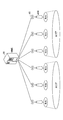
- FIG. 5 is a diagram showing an example of a distribution area according to the embodiment of the present invention. As shown in FIG. 5, an ETWS message may be distributed for each cell of the eNB 10 accommodated in the MME 30, or an ETWS message may be distributed for each area including a plurality of cells.
- step S103 the CBC 40 transmits “Write-Replace ⁇ Warning ⁇ Request” to the MME 30.
- “Write-Replace ⁇ Warning ⁇ Request” is a signal transmitted from the CBC 40 to the MME 30 and transmitted from the MME 30 to the eNB 10 for requesting emergency information distribution, and includes information such as a disaster type, a message text, and a distribution area.
- the MME 30 transmits “Write-Replace ⁇ Warning ⁇ Confirm” to the CBC 40 (S104).
- “Write-Replace ⁇ Warning ⁇ Confirm” is a response to "Write-Replace ⁇ Warning ⁇ Request”.
- step S105 the CBC 40 transmits an emergency information distribution response to the CBE 50.
- step S106 the MME 30 checks the area.
- the eNB 10 of the distribution destination is specified based on the information of the distribution area included in the received “Write-Replace ⁇ Warning ⁇ Request”. Subsequently, the MME 30 transmits “Write-Replace ⁇ Warning ⁇ Request” to the specified eNB 10 (S107).
- the eNB 10 performs a distribution area determination process.
- a cell list is set as a distribution area in the received “Write-Replace ⁇ Warning ⁇ Request”
- the eNB 10 searches the cell list under the own station in the cell list, and sends a message of the message included in the cell list to the cell included in the cell list. Broadcasting is performed. If, for example, a TAI (Tracking @ Area ⁇ Identity) list is set as the distribution area, the TAI under the control of the own station is searched, and the message is distributed to cells included in the corresponding TA. Even when the distribution area is a list of other areas (for example, EA: Emergency @ Area), the broadcast of the message is similarly performed to the cells included in the area.
- TAI Track @ Area ⁇ Identity
- step S109 the eNB 10 transmits an ETWS paging signal to the UE 20 in a cell included in the distribution area determined in step S108. Subsequently, the eNB 10 performs the broadcast distribution based on the broadcast information to the UE 20. Subsequently, the eNB 10 transmits “Write-Replace ⁇ Warning ⁇ Response” to the MME 30.
- the MME 30 may be replaced with an RNC (Radio Network Controller) or an AMF, and an ETWS message may be delivered in a similar sequence in a 3G system or an NR system.
- RNC Radio Network Controller
- AMF Access Management Function
- FIG. 6 is a diagram illustrating a communication system according to an embodiment of the present invention.
- the communication system shown in FIG. 6 includes EPC, 5GC, CBC 40, MME 30, AMF 60, eNB 10, UE 20A located in EPC, and UE 20B located in 5GC.
- the MME 30 and the eNB 10 are connected by an S1-AP interface.
- the MME 30 and the eNB 10 are connected by an NG-AP interface.
- the UE 20A is connected to the eNB 10, and is located in the EPC.
- the UE 20B is connected to the eNB 10 by the EN-DC described with reference to FIG. 3, and is located in 5GC.
- the CBC 40 may belong to the EPC, or may be located at any position on the network without belonging to the EPC.
- the CBC 40 when making a distribution request for emergency information, the CBC 40 transmits “Write-Replace Warning Request” to the MME 30. Furthermore, when the base station connected to the 5GC is not connected to the EPC or the MME 30, it is necessary to deliver emergency information to the base station. Therefore, the “Write-Replace Warning Request” is transmitted via the AMF 60. Sent.
- the UE 20B residing in the 5GC transmits the ETWS message to the eNB 10 from the CBC 40 via the MME 30 to the eNB 10 based on the “ETWS message” by paging, which is RRC (Radio Resource Control) signaling, based on the “Write-Replace Warning Request”. And system information.
- RRC Radio Resource Control
- “Write-Replace ⁇ Warning ⁇ Request” is transmitted from the CBC 40 to the eNB 10 via the AMF 60, there is a possibility that an ETWS message is redundantly processed in the eNB 10 or the UE 20. Therefore, when emergency information distribution is started in a network including the eNB 10 connected to a plurality of core networks, the same emergency information as the emergency information distributed via a certain core network is started from another core network. It is necessary to deter.
- FIG. 7 is a flowchart for explaining the operation of CBC 40 in the embodiment of the present invention.
- FIG. 7 is a flowchart for explaining the area specifying process when the CBC 40 issues a distribution request for emergency information. This corresponds to the processing in step S102 in FIG.
- the CBC 40 has information on the eNB 10 or the area connected to both the 5GC and the MME.
- step S11 the CBC 40 selects one area from unconfirmed area candidates to which emergency information is to be distributed. Subsequently, the CBC 40 determines whether the selected area connects to both 5GC and MME (S12). When the selected area is connected to both 5GC and MME (YES in S12), the process proceeds to step S13, and when the selected area is not connected to both 5GC and MME (NO in S12), the process proceeds to step S14.
- step S13 the CBC 40 suppresses transmission of one of the area mails in the area connected to both the 5GC and the MME.
- step S14 the CBC 40 transmits an area mail in an area not connected to both the 5GC and the MME.
- the suppression of the area mail transmission in step S13 may be executed by not including an area to be suppressed in the distribution area of “Write-Replace ⁇ Warning ⁇ Request”.
- the transmission of the area mail in step S14 may be executed by including the area to be transmitted in the distribution area of “Write-Replace ⁇ Warning ⁇ Request”.
- step S15 it is determined whether all areas have been confirmed. If all the areas have been confirmed (YES in S15), the flow ends, and if not all the areas have been confirmed (NO in S15), the flow proceeds to step S11.
- steps S11 to S15 "area” may be replaced with “base station” or “cell”, and "area mail” may be another name if it is a message that delivers emergency information by ETWS or the like. It may be.
- step S12 it is determined whether the area is connected to three or more core networks.
- step S13 area mail transmission is performed in a core network other than one core network among the three or more core networks. May be suppressed.
- the CBC 40 suppresses any one of the area mail transmission areas in the area connected to both 5GC and MME, and does not connect to both 5GC and MME.
- Area mail can be sent in the area. That is, when emergency information distribution is activated in a network including the eNB 10 connected to a plurality of core networks, distribution of the same emergency information as that distributed via a certain core network is performed from another core network. Activation can be suppressed.
- FIG. 8 is a flowchart for explaining the operation of MME 30 or AMF 60 in the embodiment of the present invention.
- FIG. 8 is a flowchart for explaining the area specifying process when the MME 30 or the AMF 60 issues a distribution request for emergency information. This corresponds to the process in step S106 in FIG. It is assumed that the MME 30 or the AMF 60 has information on the eNB 10 or the area connected to both the 5GC and the MME.
- the flowchart illustrated in FIG. 8 is executed only for one of the MME 30 and the AMF 60.
- step S21 the MME 30 or the AMF 60 receives "Write-Replace ⁇ Warning ⁇ Request". Subsequently, the MME 30 or the AMF 60 selects one area from unconfirmed area candidates based on the information of the distribution area included in “Write-Replace ⁇ Warning ⁇ Request”. Subsequently, the MME 30 or the AMF 60 determines whether the selected area connects to both the 5GC and the MME (S23). If the selected area connects to both 5GC and MME (YES in S23), the process proceeds to step S24, and if the selected area does not connect to both 5GC and MME (NO in S23), the process proceeds to step S25.
- step S24 the MME 30 or the AMF 60 suppresses area mail transmission in an area connected to both the 5GC and the MME.
- the suppression of the area mail transmission in step S24 may be performed by not including the area to be suppressed in the distribution area of “Write-Replace ⁇ Warning ⁇ Request”. Further, the suppression of the area mail transmission in step S24 may be executed by not performing the area mail transmission.
- the transmission of the area mail in step S25 may be executed by including the area to be transmitted in the distribution area of “Write-Replace ⁇ Warning ⁇ Request”. Further, the area mail transmission in step S25 may be executed by performing an area mail transmission.
- step S25 the MME 30 or the AMF 60 transmits an area mail in an area not connected to both the 5GC and the MME.
- step S26 it is determined whether all areas have been confirmed. If all the areas have been confirmed (YES in S26), the flow ends, and if not all the areas have been confirmed (NO in S26), the flow proceeds to step S22.
- step S21 to S26 "area” may be replaced with “base station” or “cell”, and "area mail” may be another name if it is a message that delivers emergency information by ETWS or the like. It may be.
- step S23 it may be determined whether the area is connected to three or more core networks.
- the flowchart of FIG. 8 may be executed in a device of a core network other than one core network.
- the MME 30 or the AMF 60 suppresses any one of the area mail transmission areas in the area connected to both the 5GC and the MME, and prevents the area mail from being transmitted to both the 5GC and the MME.
- Area mail can be sent in areas that are not connected. That is, when emergency information distribution is activated in a network including the eNB 10 connected to a plurality of core networks, distribution of the same emergency information as that distributed via a certain core network is performed from another core network. Activation can be suppressed.
- FIG. 9 is a flowchart for explaining the operation of eNB 10 in the embodiment of the present invention.
- FIG. 9 is a flowchart for explaining the area specifying process when the eNB 10 receives the urgent information distribution request. This corresponds to the processing in step S108 in FIG.
- the eNB 10 has information on the eNB 10 or the area connected to both the 5GC and the MME.
- step S31 the eNB 10 receives "Write-Replace ⁇ Warning ⁇ Request". Subsequently, the eNB 10 determines whether the own device is connected to both the 5GC and the MME (S32). When the own device is connected to both 5GC and MME (YES in S32), the process proceeds to step S33, and when the own device is not connected to both 5GC and MME (NO in S32), the process proceeds to step S34.
- step S33 the eNB 10 suppresses the area mail transmission of either 5GC or MME, and ends the flow.
- the eNB 10 transmits the area mail and ends the flow.
- step S33 when the own device is connected to three or more core networks, the area mail transmission activated by a core network other than one core network among the three or more core networks is suppressed. Is also good.
- "area mail" may be another name as long as it is a message for delivering emergency information by ETWS or the like.
- the eNB 10 suppresses any one area mail transmission in the area connected to both 5GC and MME among the areas to which the area mail is transmitted, and does not connect to both 5GC and MME.
- Area mail can be sent in the area. That is, when emergency information distribution is activated in a network including the eNB 10 connected to a plurality of core networks, distribution of the same emergency information as that distributed via a certain core network is performed from another core network. Activation can be suppressed.
- the eNB 10, the MME 30, the AMF 60, or the CBC 40 suppresses any area mail transmission in an area connected to both the 5GC and the MME among the areas to which the area mail is to be transmitted, and controls both the 5GC and the MME.
- Area mail can be transmitted in an area not connected to. Therefore, when emergency information distribution is started in a network including the eNB 10 connected to a plurality of core networks, distribution of the same emergency information as that distributed via a certain core network is performed from another core network. Activation can be suppressed.
- the base station device connected to the plurality of core networks can appropriately deliver the message to the user device.
- the eNB 10 and the UE 20 include a function for implementing the above-described embodiment. However, each of the eNB 10 and the UE 20 may include only some of the functions in the embodiment.
- FIG. 10 is a diagram illustrating an example of a functional configuration of the eNB 10 according to the embodiment of the present invention.
- the eNB 10 includes a transmitting unit 110, a receiving unit 120, a setting unit 130, and a control unit 140.
- the functional configuration shown in FIG. 10 is only an example.
- the names of the functional divisions and the functional units may be any as long as the operation according to the embodiment of the present invention can be performed.
- the transmitting unit 110 has a function of generating a signal to be transmitted to the UE 20 and transmitting the signal wirelessly. Further, transmitting section 110 transmits a message between network nodes to another network node.
- the receiving unit 120 includes a function of receiving various signals transmitted from the UE 20 and acquiring, for example, information of a higher layer from the received signals. Further, transmitting section 110 has a function of transmitting NR-PSS, NR-SSS, NR-PBCH, DL / UL control signal, and the like to UE 20. Further, receiving section 120 receives a message between network nodes from another network node.
- the setting unit 130 stores in the storage device the setting information set in advance and various setting information to be transmitted to the UE 20, and reads out the setting information from the storage device as needed.
- the content of the setting information is, for example, setting information related to communication of the UE 20, such as setting of a radio bearer or a secondary cell.
- the control unit 140 controls the communication including the UE 20 and the EN-DC as described in the embodiment. Further, the control unit 140 can communicate with the EPC and the 5GC. A function unit related to signal transmission in control unit 140 may be included in transmission unit 110, and a function unit related to signal reception in control unit 140 may be included in reception unit 120. Note that the MME 30, the CBC 40, or the AMF 60 may have the same function unit as the eNB 10, except for a function related to a wireless communication interface with the UE 20.
- FIG. 11 is a diagram illustrating an example of a functional configuration of the UE 20.
- the UE 20 includes a transmitting unit 210, a receiving unit 220, a setting unit 230, and a control unit 240.
- the functional configuration shown in FIG. 11 is only an example.
- the names of the functional divisions and the functional units may be any as long as the operation according to the embodiment of the present invention can be performed.
- the transmission unit 210 creates a transmission signal from transmission data, and transmits the transmission signal wirelessly.
- the receiving unit 220 wirelessly receives various signals, and obtains a higher layer signal from the received physical layer signal. Further, the receiving section 220 has a function of receiving NR-PSS, NR-SSS, NR-PBCH, DL / UL / SL control signals, and the like transmitted from the eNB 10.
- the transmission unit 210 transmits the PSCCH (Physical Sidelink Shared Channel), the PSSCH (Physical Sidelink Shared Channel), the PSDCH (Physical Sidelink Discovery Channel), and the PSBCH (Physical Sidelink Broadcast Channel) to other UEs 20 as D2D communication.
- the receiving unit 120 receives a PSCCH, a PSSCH, a PSDCH, a PSBCH, or the like from another UE 20.
- the setting unit 230 stores various setting information received from the eNB 10 or the UE 20 by the receiving unit 220 in a storage device, and reads out the setting information from the storage device as needed.
- the setting unit 230 also stores preset setting information.
- the content of the setting information is, for example, setting information related to communication of the UE 20, such as setting of a radio bearer or a secondary cell.
- the control unit 240 performs wireless communication including EN-DC as described in the embodiment. Further, the control unit 240 receives information related to wireless communication from the eNB 10, controls wireless communication of the UE 20 based on the information, and reports necessary information to the eNB 10.
- the control unit 240 can be located in EPC or 5GC.
- a function unit related to signal transmission in the control unit 240 may be included in the transmission unit 210, and a function unit related to signal reception in the control unit 240 may be included in the reception unit 220.
- each functional block may be realized by one device in which a plurality of elements are physically and / or logically combined, or two or more devices physically and / or logically separated from each other directly and directly. And / or indirectly (for example, wired and / or wireless), and may be implemented by these multiple devices.
- both the eNB 10 and the UE 20 according to the embodiment of the present invention may function as a computer that performs processing according to the embodiment of the present invention.
- FIG. 12 is a diagram illustrating an example of a hardware configuration of a wireless communication device that is the eNB 10 or the UE 20 according to the embodiment of the present invention.
- Each of the above-described eNB 10 and UE 20 may be physically configured as a computer device including a processor 1001, a storage device 1002, an auxiliary storage device 1003, a communication device 1004, an input device 1005, an output device 1006, a bus 1007, and the like. .
- the term “apparatus” can be read as a circuit, a device, a unit, or the like.
- the hardware configuration of the eNB 10 and the UE 20 may be configured to include one or more of the devices indicated by 1001 to 1006 illustrated in the drawing, or may be configured without including some devices.
- the functions of the eNB 10 and the UE 20 are performed by reading predetermined software (program) on hardware such as the processor 1001 and the storage device 1002, so that the processor 1001 performs an arithmetic operation, and the communication by the communication device 1004, the storage device 1002, and the auxiliary This is realized by controlling reading and / or writing of data in the storage device 1003.
- the processor 1001 controls the entire computer by operating an operating system, for example.
- the processor 1001 may be configured by a central processing unit (CPU: Central Processing Unit) including an interface with a peripheral device, a control device, an arithmetic device, a register, and the like.
- CPU Central Processing Unit
- the processor 1001 reads out a program (program code), a software module, or data from the auxiliary storage device 1003 and / or the communication device 1004 to the storage device 1002, and executes various processes according to these.
- a program program that causes a computer to execute at least a part of the operation described in the above embodiment is used.
- the transmission unit 110, the reception unit 120, the setting unit 130, and the control unit 140 of the eNB 10 illustrated in FIG. 10 may be realized by a control program stored in the storage device 1002 and operated by the processor 1001. Further, for example, the transmission unit 210, the reception unit 220, the setting unit 230, and the control unit 240 of the UE 20 illustrated in FIG.
- 11 may be realized by a control program stored in the storage device 1002 and operated by the processor 1001. . Although it has been described that the above-described various processes are executed by one processor 1001, the processes may be executed simultaneously or sequentially by two or more processors 1001. Processor 1001 may be implemented with one or more chips. Note that the program may be transmitted from a network via a telecommunication line.
- the storage device 1002 is a computer-readable recording medium and is, for example, at least one of a ROM (Read Only Memory), an EPROM (Erasable Programmable ROM), an EEPROM (Electrically Erasable Programmable ROM), and a RAM (Random Access Memory). It may be configured.
- the storage device 1002 may be called a register, a cache, a main memory (main storage device), or the like.
- the storage device 1002 can store a program (program code), a software module, and the like that can be executed to execute the processing according to an embodiment of the present invention.
- the auxiliary storage device 1003 is a computer-readable recording medium, for example, an optical disk such as a CD-ROM (Compact Disc), a hard disk drive, a flexible disk, a magneto-optical disk (for example, a compact disk, a digital versatile disk, Blu -Ray (registered trademark) disk), smart card, flash memory (eg, card, stick, key drive), floppy (registered trademark) disk, magnetic strip, or the like.
- the auxiliary storage device 1003 may be called an auxiliary storage device.
- the storage medium described above may be, for example, a database including the storage device 1002 and / or the auxiliary storage device 1003, a server, or any other suitable medium.
- the communication device 1004 is hardware (transmitting / receiving device) for performing communication between computers via a wired and / or wireless network, and is also referred to as, for example, a network device, a network controller, a network card, a communication module, and the like.
- the transmitting unit 110 and the receiving unit 120 of the eNB 10 may be realized by the communication device 1004.
- the transmission unit 210 and the reception unit 220 of the UE 20 may be realized by the communication device 1004.
- the input device 1005 is an input device (for example, a keyboard, a mouse, a microphone, a switch, a button, a sensor, and the like) that receives an external input.
- the output device 1006 is an output device that performs output to the outside (for example, a display, a speaker, an LED lamp, and the like). Note that the input device 1005 and the output device 1006 may have an integrated configuration (for example, a touch panel).
- the devices such as the processor 1001 and the storage device 1002 are connected by a bus 1007 for communicating information.
- the bus 1007 may be configured by a single bus, or may be configured by a different bus between devices.
- the eNB 10 and the UE 20 each include hardware such as a microprocessor, a digital signal processor (DSP), an ASIC (Application Specific Integrated Circuit), a PLD (Programmable Logic Device), and an FPGA (Field Programmable Gate Array). And some or all of the functional blocks may be realized by the hardware.
- the processor 1001 may be implemented by at least one of these hardware.
- a network node connected to a plurality of base station apparatuses connected to one or a plurality of core networks belonging to different systems, A control unit for controlling the delivery of the same emergency information as the delivery of emergency information activated by the first core network to be prevented from being activated by a core network other than the first core network, and a base station; A transmission unit for transmitting a message for the device to deliver emergency information.
- the MME 30, the AMF 60, or the CBC 40 suppresses any one of the area mail transmission targets in the area connected to both the 5GC and the MME, and does not connect to both the 5GC and the MME.
- Area mail can be sent in the area. Therefore, when emergency information distribution is started in a network including the eNB 10 connected to a plurality of core networks, distribution of the same emergency information as that distributed via a certain core network is performed from another core network. Activation can be suppressed. That is, a base station device connected to a plurality of core networks can appropriately deliver a message to a user device.
- the control unit when an area including the first base station device or the plurality of base station devices is connected to a plurality of core networks, the control unit may be configured to perform the operation in a core network other than the first core network among the plurality of core networks.
- Information indicating that emergency information is not to be distributed to the first base station device or the area, and indicating that emergency information is to be distributed to the first base station device or the area in the first core network Information may be included in the message.
- the control unit when an area including the first base station device or the plurality of base station devices is not connected to a plurality of core networks, performs distribution of emergency information to the first base station device or the area.
- the indicated information may be included in the message.
- CBC 40 can transmit area mail in an area that is not connected to a plurality of core networks.
- the control unit When the area including the first base station device or the plurality of base station devices is connected to a plurality of core networks, the control unit does not perform delivery of emergency information to the first base station device or the area. Alternatively, information indicating that emergency information is not distributed to the first base station device or the area may be included in the message.
- the MME 30 or the AMF 60 distributes the same emergency information as the emergency information distributed via a certain core network. Can be prevented from being activated from other core networks.
- the control unit may perform distribution of emergency information to the first base station device or the area.
- information indicating that emergency information is delivered to the first base station device or the area may be included in the message.
- the MME 30 or the AMF 60 can transmit an area mail in an area not connected to a plurality of core networks.
- a base station device connected to a plurality of core networks belonging to different systems, wherein a receiving unit for receiving a message for delivering emergency information, A control unit configured to control the delivery of the same emergency information as that of the emergency information activated by the first core network from being activated by a core network other than the first core network; There is provided a base station apparatus having a transmission unit that distributes emergency information to a user apparatus based on the transmission information.
- the eNB 10, the MME 30, the AMF 60, or the CBC 40 suppresses any one of the area mail transmission areas in the area connected to both the 5GC and the MME, and suppresses the transmission of the area mail to both the 5GC and the MME.
- Area mail can be sent in areas that are not connected. Therefore, when emergency information distribution is started in a network including the eNB 10 connected to a plurality of core networks, distribution of the same emergency information as that distributed via a certain core network is performed from another core network. Activation can be suppressed. That is, a base station device connected to a plurality of core networks can appropriately deliver a message to a user device.
- the operations of a plurality of functional units may be physically performed by one component, or the operations of one functional unit may be physically performed by a plurality of components.
- the order of the processing may be changed as long as there is no contradiction.
- the base station device and the user device have been described using a functional block diagram for convenience of description of the process, such a device may be realized by hardware, software, or a combination thereof.
- Software operated by the processor of the base station apparatus according to the embodiment of the present invention and software operated by the processor of the user apparatus according to the embodiment of the present invention are a random access memory (RAM), a flash memory, and a read-only memory, respectively. (ROM), EPROM, EEPROM, register, hard disk (HDD), removable disk, CD-ROM, database, server, or any other suitable storage medium.
- the notification of information is not limited to the aspect / embodiment described in this specification, and may be performed by another method.
- the notification of information includes physical layer signaling (for example, DCI (Downlink Control Information), UCI (Uplink Control Information)), higher layer signaling (for example, RRC (Radio Resource Control) signaling, MAC (Medium Access Control) signaling, It may be implemented by broadcast information (MIB (Master Information Block), SIB (System Information Block)), other signals, or a combination thereof, and RRC signaling may be called an RRC message, for example, RRC message.
- a connection setup (RRC (Connection Setup) message, an RRC connection reconfiguration (RRC Connection Reconfiguration) message, or the like may be used.
- Each aspect / embodiment described in this specification includes LTE (Long Term Evolution), LTE-A (LTE-Advanced), SUPER 3G, IMT-Advanced, 4G, 5G, FRA (Future Radio Access), W-CDMA.
- LTE Long Term Evolution
- LTE-A Long Term Evolution-Advanced
- SUPER 3G IMT-Advanced
- 4G 5G
- FRA Full Radio Access
- W-CDMA Wideband
- GSM registered trademark
- CDMA2000 Code Division Multiple Access 2000
- UMB Ultra Mobile Broadband
- IEEE 802.11 Wi-Fi
- IEEE 802.16 WiMAX
- IEEE 802.20 UWB (Ultra-WideBand
- the present invention may be applied to a system using Bluetooth (registered trademark), another appropriate system, and / or a next-generation system extended based on the system.
- the specific operation described as being performed by the base station apparatus in this specification may be performed by an upper node (upper node) in some cases.
- an upper node In a network including one or a plurality of network nodes (network @ nodes) having a base station apparatus, various operations performed for communication with a user apparatus are performed by a base station apparatus and / or a network other than the base station apparatus.
- a node eg, but not limited to MME or S-GW, etc.
- the case where the number of other network nodes other than the base station apparatus is one is illustrated, but a combination of a plurality of other network nodes (for example, MME and S-GW) may be used.
- the user equipment is provided by those skilled in the art as a subscriber station, mobile unit, subscriber unit, wireless unit, remote unit, mobile device, wireless device, wireless communication device, remote device, mobile subscriber station, access terminal, mobile terminal, wireless terminal. It may also be called a terminal, a remote terminal, a handset, a user agent, a mobile client, a client, or some other suitable term.
- a base station device may also be referred to by those skilled in the art as an NB (NodeB), an eNB (evolved @ NodeB), a gNB (Next @ generation @ NodeB, @ NR @ nodeB), a base station (Base @ Station), or some other suitable terminology. is there.
- determining may encompass a wide variety of actions.
- the “judgment” and “decision” are, for example, judgment (judging), calculation (computing), processing (processing), deriving (investigating), investigating (looking up) (for example, table , A search in a database or another data structure), ascertaining a thing as “determining", “determining", and the like.
- “determining” and “determining” include receiving (eg, receiving information), transmitting (eg, transmitting information), input (input), output (output), and accessing. (Accessing) (e.g., accessing data in a memory) may be regarded as "determined” or "determined”.
- judgment and “decision” mean that resolving, selecting, selecting, establishing, establishing, comparing, etc. are regarded as “judgment” and “determined”. May be included. That is, “judgment” and “decision” may include deeming any operation as “judgment” and “determined”.
- eNB 10 is an example of a base station device.
- the CBC 40, the MME 30, or the AMF 60 is an example of a network node.
- "Write-Replace ⁇ Warning ⁇ Request" is an example of a message for distributing emergency information.
- Core networks belonging to different systems are examples of EPC or 5GC.
Landscapes
- Engineering & Computer Science (AREA)
- Computer Networks & Wireless Communication (AREA)
- Signal Processing (AREA)
- Business, Economics & Management (AREA)
- Health & Medical Sciences (AREA)
- Emergency Management (AREA)
- Environmental & Geological Engineering (AREA)
- Public Health (AREA)
- Mobile Radio Communication Systems (AREA)
Abstract
ネットワークノードは、異なるシステムに属する1又は複数のコアネットワークに、それぞれ接続される複数の基地局装置と接続し、前記複数のコアネットワークのうち、第1のコアネットワークによって起動される緊急情報の配信と同一の緊急情報の配信が、前記第1のコアネットワーク以外のコアネットワークによって起動されないように制御する制御部と、基地局装置が緊急情報を配信するためのメッセージを送信する送信部とを有する。
Description
本発明は、無線通信システムにおけるネットワークノード及び基地局装置に関する。
3GPP(3rd Generation Partnership Project)では、システム容量の更なる大容量化、データ伝送速度の更なる高速化、無線区間における更なる低遅延化等を実現するために、5GあるいはNR(New Radio)と呼ばれる無線通信方式(以下、当該無線通信方式を「5G」あるいは「NR」という。)の検討が進んでいる。5Gでは、10Gbps以上のスループットを実現しつつ無線区間の遅延を1ms以下にするという要求条件を満たすために、様々な無線技術の検討が行われている。
NRでは、LTE(Long Term Evolution)のネットワークアーキテクチャにおけるコアネットワークであるEPC(Evolved Packet Core)に対応する5GC(5G Core Network)及びLTEのネットワークアーキテクチャにおけるRAN(Radio Access Network)であるE-UTRAN(Evolved Universal Terrestrial Radio Access Network)に対応するNG-RAN(Next Generation - Radio Access Network)を含むネットワークアーキテクチャが検討されている(例えば非特許文献1)。
3GPP TS 38.401 V15.1.0(2018-03)
5GC及びEPCの共用運用を行う基地局装置を介して、ユーザ装置が5GCに在圏している場合、EPC側からの緊急情報配信メッセージと5GC側からの緊急情報配信メッセージとが重複して受信されることがあった。
本発明は上記の点に鑑みてなされたものであり、複数のコアネットワークに接続される基地局装置が、ユーザ装置にメッセージを適切に配信することを目的とする。
開示の技術によれば、異なるシステムに属する1又は複数のコアネットワークに、それぞれ接続される複数の基地局装置と接続するネットワークノードであって、前記複数のコアネットワークのうち、第1のコアネットワークによって起動される緊急情報の配信と同一の緊急情報の配信が、前記第1のコアネットワーク以外のコアネットワークによって起動されないように制御する制御部と、基地局装置が緊急情報を配信するためのメッセージを送信する送信部とを有するネットワークノードが提供される。
開示の技術によれば、複数のコアネットワークに接続される基地局装置が、ユーザ装置にメッセージを適切に配信することができる。
以下、図面を参照して本発明の実施の形態を説明する。なお、以下で説明する実施の形態は一例であり、本発明が適用される実施の形態は、以下の実施の形態に限られない。
本発明の実施の形態の無線通信システムの動作にあたっては、適宜、既存技術が使用される。ただし、当該既存技術は、例えば既存のLTEであるが、既存のLTEに限られない。また、本明細書で使用する用語「LTE」は、特に断らない限り、LTE-Advanced、及び、LTE-Advanced以降の方式(例:NR又は5G)を含む広い意味を有するものとする。
また、以下で説明する本発明の実施の形態では、既存のLTEで使用されているSS(Synchronization Signal)、PSS(Primary SS)、SSS(Secondary SS)、PBCH(Physical broadcast channel)、PRACH(Physical RACH)、DL(Downlink)、UL(Uplink)等の用語を使用している。これは記載の便宜上のためであり、これらと同様の信号、機能等が他の名称で呼ばれてもよい。
また、本発明の実施の形態において、複信(Duplex)方式は、TDD(Time Division Duplex)方式でもよいし、FDD(Frequency Division Duplex)方式でもよいし、又はそれ以外(例えば、Flexible Duplex等)の方式でもよい。
また、以下の説明において、送信ビームを用いて信号を送信する方法は、プリコーディングベクトルが乗算された(プリコーディングベクトルでプリコードされた)信号を送信するデジタルビームフォーミングであってもよいし、RF(Radio Frequency)回路内の可変移相器を用いてビームフォーミングを実現するアナログビームフォーミングであってもよい。同様に、受信ビームを用いて信号を受信する方法は、所定の重みベクトルを受信した信号に乗算するデジタルビームフォーミングであってもよいし、RF回路内の可変位相器を用いてビームフォーミングを実現するアナログビームフォーミングであってもよい。デジタルビームフォーミングとアナログビームフォーミングを組み合わせたハイブリッドビームフォーミングが適用されてもよい。また、送信ビームを用いて信号を送信することは、特定のアンテナポートで信号を送信することであってもよい。同様に、受信ビームを用いて信号を受信することは、特定のアンテナポートで信号を受信することとであってもよい。アンテナポートとは、3GPPの規格で定義されている論理アンテナポート又は物理アンテナポートを指す。
なお、送信ビーム及び受信ビームの形成方法は、上記の方法に限られない。例えば、複数アンテナを備える基地局装置又はユーザ装置において、それぞれのアンテナの角度を変える方法を用いてもよいし、プリコーディングベクトルを用いる方法とアンテナの角度を変える方法を組み合わせる方法を用いてもよいし、異なるアンテナパネルを切り替えて利用してもよいし、複数のアンテナパネルを合わせて使う方法を組み合わせる方法を用いてもよいし、その他の方法を用いてもよい。また、例えば、高周波数帯において、複数の互いに異なる送信ビームが使用されてもよい。複数の送信ビームが使用されることを、マルチビーム運用といい、ひとつの送信ビームが使用されることを、シングルビーム運用という。
また、本発明の実施の形態において、無線パラメータ等が「設定される」とは、所定の値が予め設定(Pre-configure)又は規定されることであってもよいし、基地局装置又はユーザ装置から通知される無線パラメータが設定されることであってもよい。
図1は、本発明の実施の形態におけるネットワークアーキテクチャの例(1)を示す図である。図1は、LTEのネットワークアーキテクチャにおいて、C-plane(Control plane)の構成を示す。図1に示されるように、アクセス層(Access Stratum, AS)において、UE20(User Equipment)とE-UTRANとは、無線インタフェース(Uu:Radio interface between UTRAN and the User equipment)を介して無線プロトコルを用いて接続される。また、アクセス層において、E-UTRANとEPCとは、S1インタフェースを介してS1プロトコルを用いて接続される。S1インタフェースとは、E-UTRANに含まれるeNB10(evolved NodeB)と、EPCとの間の論理的インタフェースであり、E-UTRANとEPCとの間の相互接続ポイントを提供し、参照ポイントでもある。
図1に示されるように、非アクセス層(Non-Access Stratum, NAS)において、UEとEPCとは論理的に接続される。例えば、UEとEPC間のNAS制御プロトコルには、EMM(EPS Mobility Management)、ESM(EPS Session Management)がある。EPSとは、Evolved Packet Systemである。なお、EPCは、1又は複数のコアネットワーク装置で構成され、当該コアネットワーク装置は、eNB10又はUE20と通信を行うことができる。
図2は、本発明の実施の形態におけるネットワークアーキテクチャの例(2)を示す図である。図2は、NRのネットワークアーキテクチャにおいて、C-planeの構成を示す。図2に示されるように、アクセス層において、UE20であるUEとNG-RANとは、無線インタフェース(Uu)を介して無線プロトコルを用いて接続される。また、アクセス層において、NG-RANと5GCとは、NGインタフェースを介してNGプロトコルを用いて接続される。NGインタフェースとは、NG-RANに含まれる基地局装置であるgNB(next generation NodeB)と、5GCとの間の論理的インタフェースであり、NG-RANと5GCとの間の相互接続ポイントを提供し、参照ポイントでもある。
図2に示されるように、非アクセス層(NAS)において、UEと5GCとは論理的に接続される。例えば、UEと5GC間のNAS制御プロトコルには、CM(Connection Management)、SM(Session Management)がある。なお、5GCは、1又は複数のコアネットワーク装置で構成され、当該コアネットワーク装置は、eNB10又はUE20と通信を行うことができる。
図3は、本発明の実施の形態におけるC-planeの接続形態の例を示す図である。図3は、UEとEPC及び5GCとの間で確立されるC-planeの接続形態を示す。
図3に示されるように、C-planeの接続形態として、UE20AとEPCとは、LTE-NASにおいて、論理的に接続される。UE20Aは、eNB10と無線インタフェースを介して接続される。eNBは、EPCとS1インタフェースを介して接続される。U-plane(User plane)は、eNB10を介してUE20Aと接続される。
また、図3に示されるように、C-planeの接続形態として、UE20Bと5GCとは、参照ポイントN1を介して、論理的に接続される。参照ポイントN1は、UEと5GCのNF(network function)のひとつであるAMF(Access and Mobility Management Function)との間の参照ポイントである。UE20Bは、NRのネットワークノード例えばgNBと無線インタフェースを介して接続される。NRのネットワークノードは、5GCと参照ポイントN2を介して接続される。参照ポイントN2は、RANと5GCのNFのひとつであるAMFとの間の参照ポイントである。U-planeは、eNB及びNRのネットワークノードを介してUEと接続される。図3に示されるUE20Bの運用を、NRノンスタンドアロン(NSA)といい、LTE-NRデュアルコネクティビティ(E-UTRA-NR Dual connectivity, EN-DC)が適用された通信が実行される。
図4は、本発明の実施の形態におけるメッセージ配信手順を説明するためのシーケンス図である。図4は、LTEシステムにおいて、例えば地震速報のようなETWS(Earthquake and Tsunami Warning System)のメッセージが配信されるシーケンスを示す。図4に示されるCBE50(Cell Broadcast Entity)は、気象庁等の緊急情報の配信元である。CBC40(Cell Broadcast Center)は、CBE50と接続されている。MME30(Mobility Management Entity)は、複数のeNB10を収容しモビリティ制御機能等を提供するネットワークノードである。
ステップS101において、CBE50は、緊急情報配信要求をCBC40に送信する。続いて、CBC40は、緊急情報に係るメッセージを作成し、メッセージが配信されるエリアを特定する(S102)。エリアの特定は、例えば、セル単位で特定されてもよいし、エリア単位で特定されてもよい。
図5は、本発明の実施の形態における配信エリアの例を示す図である。図5に示されるように、MME30に収容されるeNB10のセルごとに、ETWSのメッセージが配信されてもよいし、複数のセルを含むエリアごとに、ETWSのメッセージが配信されてもよい。
図4に戻る。ステップS103において、CBC40は、「Write-Replace Warning Request」をMME30に送信する。「Write-Replace Warning Request」は、CBC40からMME30に送信され、MME30からeNB10に送信される緊急情報配信の要求を行う信号であり、災害種別、メッセージ本文及び配信エリア等の情報が含まれる。続いて、MME30は、「Write-Replace Warning Confirm」をCBC40に送信する(S104)。「Write-Replace Warning Confirm」は、「Write-Replace Warning Request」に対する応答である。ステップS105において、CBC40は、緊急情報配信応答をCBE50に送信する。
ステップS106において、MME30は、エリア確認を行う。受信した「Write-Replace Warning Request」に含まれる配信エリアの情報に基づいて、配信先のeNB10を特定する。続いて、MME30は、特定されたeNB10に「Write-Replace Warning Request」を送信する(S107)。
ステップ108において、eNB10は、配信エリア決定処理を行う。eNB10は、受信した「Write-Replace Warning Request」に、配信エリアとしてセルリストが設定されていた場合、自局配下のセルをセルリストで検索して、セルリストに含まれるセルに対してメッセージの同報配信を行う。配信エリアとして、例えばTAI(Tracking Area Identity)リストが設定されていた場合、自局配下のTAIを検索して、該当するTAに含まれるセルに対してメッセージの同報配信を行う。配信エリアがその他のエリアのリスト(例えば、EA:Emergency Area)であっても、同様に該当エリアに含まれるセルに対してメッセージの同報配信を行う。
ステップS109において、eNB10は、ステップS108で決定された配信エリアに含まれるセルにおいて、ETWSのページング信号をUE20に送信する。続いて、eNB10は、報知情報による同報配信をUE20に行う。続いて、eNB10は、「Write-Replace Warning Response」をMME30に送信する。
なお、例えば、MME30が、RNC(Radio Network Controller)又はAMFに置換されて、3Gシステム又はNRシステムにおいても同様のシーケンスでETWSのメッセージが配信されてもよい。
図6は、本発明の実施の形態における通信システムを説明するための図である。図6に示される通信システムには、EPC、5GC、CBC40、MME30、AMF60、eNB10、EPCに在圏しているUE20A、5GCに在圏しているUE20Bが含まれる。MME30とeNB10は、S1-APインタフェースで接続されている。MME30とeNB10は、NG-APインタフェースで接続されている。UE20Aは、eNB10と接続し、EPCに在圏している。UE20Bは、図3で説明したEN-DCにより、eNB10と接続し、5GCに在圏している。なお、CBC40は、EPCに属していてもよいし、EPCに属さずにネットワーク上のいずれの位置に配置されてもよい。
図6に示される通信システムにおいて、緊急情報の配信要求を行う場合、CBC40が、「Write-Replace Warning Request」をMME30に送信する。さらに、5GCに接続している基地局がEPC又はMME30と接続していない場合、当該基地局に対して緊急情報の配信を行う必要があるため、AMF60を介して「Write-Replace Warning Request」を送信される。
ここで、5GCに在圏しているUE20Bは、CBC40からMME30を経由してeNB10に送信された「Write-Replace Warning Request」に基づいて、ETWSのメッセージをRRC(Radio Resource Control)シグナリングであるページング及びシステム情報から受信することができる。しかしながら、CBC40からAMF60を経由してeNB10に「Write-Replace Warning Request」が送信されているため、ETWSのメッセージがeNB10又はUE20において重複して処理される可能性が生じる。そのため、複数のコアネットワークに接続されるeNB10を含むネットワークにおいて緊急情報配信が起動される場合、あるコアネットワークを経由して配信された緊急情報と同一の緊急情報が、その他のコアネットワークから起動されることを抑止することが必要である。
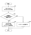
図7は、本発明の実施の形態におけるCBC40の動作を説明するためのフローチャートである。図7は、CBC40から緊急情報の配信要求を行うときのエリア特定処理を説明するためのフローチャートである。図4のステップS102における処理に対応する。CBC40は、5GC及びMME双方に接続するeNB10又はエリアに係る情報を有するものとする。
ステップS11において、CBC40は、緊急情報を配信する対象である未確認のエリア候補からエリアを1つ選択する。続いて、CBC40は、選択されたエリアが5GC及びMME双方に接続するかを判定する(S12)。選択されたエリアが5GC及びMME双方に接続する場合(S12のYES)、ステップS13に進み、選択されたエリアが5GC及びMME双方に接続しない場合(S12のNO)、ステップS14に進む。
ステップS13において、CBC40は、5GC及びMME双方に接続するエリアにおいて、いずれか一方のエリアメール送信を抑止する。ステップS14において、CBC40は、5GC及びMME双方に接続しないエリアにおいて、エリアメールを送信する。ステップS13のエリアメール送信の抑止は、「Write-Replace Warning Request」の配信エリアに抑止するエリアを含めないことによって実行されてもよい。ステップS14のエリアメールの送信は、「Write-Replace Warning Request」の配信エリアに送信するエリアを含めることによって実行されてもよい。
ステップS15において、すべてのエリアが確認されたかを判定する。すべてのエリアが確認された場合(S15のYES)、フローを終了し、すべてのエリアが確認されていない場合(S15のNO)、ステップS11に進む。
なお、ステップS11からステップS15において、「エリア」は、「基地局」又は「セル」に置換されてもよく、「エリアメール」は、ETWS等により緊急情報を配信するメッセージであれば他の名称であってもよい。
また、ステップS12において、エリアは3以上の複数のコアネットワークに接続されるかを判定し、ステップS13において、3以上の複数のコアネットワークのうち、1つのコアネットワーク以外のコアネットワークにおいてエリアメール送信を抑止してもよい。
ステップS11からステップS15の手順で、CBC40は、エリアメールの送信対象となるエリアのうち、5GC及びMME双方に接続するエリアにおいていずれか一方のエリアメール送信を抑止し、5GC及びMME双方に接続しないエリアにおいてエリアメールを送信することができる。すなわち、複数のコアネットワークに接続されるeNB10を含むネットワークにおいて緊急情報配信が起動される場合、あるコアネットワークを経由して配信された緊急情報と同一の緊急情報の配信が、その他のコアネットワークから起動されることを抑止することができる。
図8は、本発明の実施の形態におけるMME30又はAMF60の動作を説明するためのフローチャートである。図8は、MME30又はAMF60から緊急情報の配信要求を行うときのエリア特定処理を説明するためのフローチャートである。図4のステップS106における処理に対応する。MME30又はAMF60は、5GC及びMME双方に接続するeNB10又はエリアに係る情報を有するものとする。図8に示されるフローチャートは、MME30又はAMF60のいずれか一方のみに実行される。
ステップS21において、MME30又はAMF60は、「Write-Replace Warning Request」を受信する。続いて、MME30又はAMF60は、「Write-Replace Warning Request」に含まれる配信エリアの情報に基づいて、未確認のエリア候補からエリアを1つ選択する。続いて、MME30又はAMF60は、選択されたエリアが5GC及びMME双方に接続するかを判定する(S23)。選択されたエリアが5GC及びMME双方に接続する場合(S23のYES)、ステップS24に進み、選択されたエリアが5GC及びMME双方に接続しない場合(S23のNO)、ステップS25に進む。
ステップS24において、MME30又はAMF60は、5GC及びMME双方に接続するエリアにおいて、エリアメール送信を抑止する。ステップS24のエリアメール送信の抑止は、「Write-Replace Warning Request」の配信エリアに抑止するエリアを含めないことによって実行されてもよい。また、ステップS24のエリアメール送信の抑止は、エリアメール送信を行わないことによって実行されてもよい。ステップS25のエリアメールの送信は、「Write-Replace Warning Request」の配信エリアに送信するエリアを含めることによって実行されてもよい。また、ステップS25のエリアメール送信は、エリアメール送信を行うことによって実行されてもよい。
ステップS25において、MME30又はAMF60は、5GC及びMME双方に接続しないエリアにおいて、エリアメールを送信する。ステップS26において、すべてのエリアが確認されたかを判定する。すべてのエリアが確認された場合(S26のYES)、フローを終了し、すべてのエリアが確認されていない場合(S26のNO)、ステップS22に進む。
なお、ステップS21からステップS26において、「エリア」は、「基地局」又は「セル」に置換されてもよく、「エリアメール」は、ETWS等により緊急情報を配信するメッセージであれば他の名称であってもよい。
また、ステップS23において、エリアは3以上の複数のコアネットワークに接続されるかを判定してもよい。その場合、3以上の複数のコアネットワークそれぞれのMME30又はAMF60に対応する装置のうち、1つのコアネットワーク以外のコアネットワークの装置において図8のフローチャートを実行してもよい。
ステップS21からステップS26の手順で、MME30又はAMF60は、エリアメールの送信対象となるエリアのうち、5GC及びMME双方に接続するエリアにおいていずれか一方のエリアメール送信を抑止し、5GC及びMME双方に接続しないエリアにおいてエリアメールを送信することができる。すなわち、複数のコアネットワークに接続されるeNB10を含むネットワークにおいて緊急情報配信が起動される場合、あるコアネットワークを経由して配信された緊急情報と同一の緊急情報の配信が、その他のコアネットワークから起動されることを抑止することができる。
図9は、本発明の実施の形態におけるeNB10の動作を説明するためのフローチャートである。図9は、eNB10が緊急情報の配信要求を受信したときのエリア特定処理を説明するためのフローチャートである。図4のステップS108における処理に対応する。eNB10は、5GC及びMME双方に接続するeNB10又はエリアに係る情報を有するものとする。
ステップS31において、eNB10は、「Write-Replace Warning Request」を受信する。続いて、eNB10は、自装置が5GC及びMME双方に接続するかを判定する(S32)。自装置が5GC及びMME双方に接続する場合(S32のYES)、ステップS33に進み、自装置が5GC及びMME双方に接続しない場合(S32のNO)、ステップS34に進む。
ステップS33において、eNB10は、5GC及びMMEいずれか一方のエリアメール送信を抑止してフローを終了する。ステップS34において、eNB10は、エリアメールを送信してフローを終了する。
ステップS33において、自装置が3以上の複数のコアネットワークに接続されている場合、3以上の複数のコアネットワークのうち、1つのコアネットワーク以外のコアネットワークにより起動されたエリアメール送信を抑止してもよい。
なお、ステップS31からステップS34において、「エリアメール」は、ETWS等により緊急情報を配信するメッセージであれば他の名称であってもよい。
ステップS31からステップS34の手順で、eNB10は、エリアメールの送信対象となるエリアのうち、5GC及びMME双方に接続するエリアにおいていずれか一方のエリアメール送信を抑止し、5GC及びMME双方に接続しないエリアにおいてエリアメールを送信することができる。すなわち、複数のコアネットワークに接続されるeNB10を含むネットワークにおいて緊急情報配信が起動される場合、あるコアネットワークを経由して配信された緊急情報と同一の緊急情報の配信が、その他のコアネットワークから起動されることを抑止することができる。
上述の実施例により、eNB10、MME30、AMF60又はCBC40は、エリアメールの送信対象となるエリアのうち、5GC及びMME双方に接続するエリアにおいていずれか一方のエリアメール送信を抑止し、5GC及びMME双方に接続しないエリアにおいてエリアメールを送信することができる。したがって、複数のコアネットワークに接続されるeNB10を含むネットワークにおいて緊急情報配信が起動される場合、あるコアネットワークを経由して配信された緊急情報と同一の緊急情報の配信が、その他のコアネットワークから起動されることを抑止することができる。
すなわち、複数のコアネットワークに接続される基地局装置が、ユーザ装置にメッセージを適切に配信することができる。
(装置構成)
次に、これまでに説明した処理及び動作を実行するeNB10及びUE20の機能構成例を説明する。eNB10及びUE20は上述した実施例を実施する機能を含む。ただし、eNB10及びUE20はそれぞれ、実施例の中の一部の機能のみを備えることとしてもよい。
次に、これまでに説明した処理及び動作を実行するeNB10及びUE20の機能構成例を説明する。eNB10及びUE20は上述した実施例を実施する機能を含む。ただし、eNB10及びUE20はそれぞれ、実施例の中の一部の機能のみを備えることとしてもよい。
<eNB10>
図10は、本発明の実施の形態におけるeNB10の機能構成の一例を示す図である。図10に示されるように、eNB10は、送信部110と、受信部120と、設定部130と、制御部140とを有する。図10に示される機能構成は一例に過ぎない。本発明の実施の形態に係る動作を実行できるのであれば、機能区分及び機能部の名称はどのようなものでもよい。
図10は、本発明の実施の形態におけるeNB10の機能構成の一例を示す図である。図10に示されるように、eNB10は、送信部110と、受信部120と、設定部130と、制御部140とを有する。図10に示される機能構成は一例に過ぎない。本発明の実施の形態に係る動作を実行できるのであれば、機能区分及び機能部の名称はどのようなものでもよい。
送信部110は、UE20側に送信する信号を生成し、当該信号を無線で送信する機能を含む。また、送信部110は、ネットワークノード間メッセージを他のネットワークノードに送信する。受信部120は、UE20から送信された各種の信号を受信し、受信した信号から、例えばより上位のレイヤの情報を取得する機能を含む。また、送信部110は、UE20へNR-PSS、NR-SSS、NR-PBCH、DL/UL制御信号等を送信する機能を有する。ままた、受信部120は、ネットワークノード間メッセージを他のネットワークノードから受信する。
設定部130は、予め設定される設定情報、及び、UE20に送信する各種の設定情報を記憶装置に格納し、必要に応じて記憶装置から読み出す。設定情報の内容は、例えば、無線ベアラ又はセカンダリセルの設定等のUE20の通信に係る設定情報等である。
制御部140は、実施例において説明したように、UE20とEN-DCを含む通信の制御を行う。また、制御部140は、EPC及び5GCと通信することができる。制御部140における信号送信に関する機能部を送信部110に含め、制御部140における信号受信に関する機能部を受信部120に含めてもよい。なお、MME30、CBC40又はAMF60は、UE20との無線通信インタフェースに係る機能以外は、eNB10と同様の機能部を有してもよい。
<UE20>
図11は、UE20の機能構成の一例を示す図である。図11に示されるように、UE20は、送信部210と、受信部220と、設定部230と、制御部240とを有する。図11に示される機能構成は一例に過ぎない。本発明の実施の形態に係る動作を実行できるのであれば、機能区分及び機能部の名称はどのようなものでもよい。
図11は、UE20の機能構成の一例を示す図である。図11に示されるように、UE20は、送信部210と、受信部220と、設定部230と、制御部240とを有する。図11に示される機能構成は一例に過ぎない。本発明の実施の形態に係る動作を実行できるのであれば、機能区分及び機能部の名称はどのようなものでもよい。
送信部210は、送信データから送信信号を作成し、当該送信信号を無線で送信する。受信部220は、各種の信号を無線受信し、受信した物理レイヤの信号からより上位のレイヤの信号を取得する。また、受信部220は、eNB10から送信されるNR-PSS、NR-SSS、NR-PBCH、DL/UL/SL制御信号等を受信する機能を有する。また、例えば、送信部210は、D2D通信として、他のUE20に、PSCCH(Physical Sidelink Control Channel)、PSSCH(Physical Sidelink Shared Channel)、PSDCH(Physical Sidelink Discovery Channel)、PSBCH(Physical Sidelink Broadcast Channel)等を送信し、受信部120は、他のUE20から、PSCCH、PSSCH、PSDCH又はPSBCH等を受信する。
設定部230は、受信部220によりeNB10又はUE20から受信した各種の設定情報を記憶装置に格納し、必要に応じて記憶装置から読み出す。また、設定部230は、予め設定される設定情報も格納する。設定情報の内容は、例えば、無線ベアラ又はセカンダリセルの設定等のUE20の通信に係る設定情報等である。
制御部240は、実施例において説明したように、EN-DCを含む無線通信を行う。また、制御部240は、eNB10から無線通信に係る情報を受信して、当該情報に基づいてUE20の無線通信を制御し、必要な情報をeNB10に報告する。制御部240は、EPC又は5GCに在圏することができる。制御部240における信号送信に関する機能部を送信部210に含め、制御部240における信号受信に関する機能部を受信部220に含めてもよい。
(ハードウェア構成)
上述の本発明の実施の形態の説明に用いた機能構成図(図10及び図11)は、機能単位のブロックを示している。これらの機能ブロック(構成部)は、ハードウェア及び/又はソフトウェアの任意の組み合わせによって実現される。また、各機能ブロックの実現手段は特に限定されない。すなわち、各機能ブロックは、物理的及び/又は論理的に複数要素が結合した1つの装置により実現されてもよいし、物理的及び/又は論理的に分離した2つ以上の装置を直接的及び/又は間接的に(例えば、有線及び/又は無線)で接続し、これら複数の装置により実現されてもよい。
上述の本発明の実施の形態の説明に用いた機能構成図(図10及び図11)は、機能単位のブロックを示している。これらの機能ブロック(構成部)は、ハードウェア及び/又はソフトウェアの任意の組み合わせによって実現される。また、各機能ブロックの実現手段は特に限定されない。すなわち、各機能ブロックは、物理的及び/又は論理的に複数要素が結合した1つの装置により実現されてもよいし、物理的及び/又は論理的に分離した2つ以上の装置を直接的及び/又は間接的に(例えば、有線及び/又は無線)で接続し、これら複数の装置により実現されてもよい。
また、例えば、本発明の一実施の形態におけるeNB10及びUE20はいずれも、本発明の実施の形態に係る処理を行うコンピュータとして機能してもよい。図12は、本発明の実施の形態に係るeNB10又はUE20である無線通信装置のハードウェア構成の一例を示す図である。上述のeNB10及びUE20はそれぞれ、物理的には、プロセッサ1001、記憶装置1002、補助記憶装置1003、通信装置1004、入力装置1005、出力装置1006、バス1007等を含むコンピュータ装置として構成されてもよい。
なお、以下の説明では、「装置」という文言は、回路、デバイス、ユニット等に読み替えることができる。eNB10及びUE20のハードウェア構成は、図に示した1001~1006で示される各装置を1つ又は複数含むように構成されてもよいし、一部の装置を含まずに構成されてもよい。
eNB10及びUE20における各機能は、プロセッサ1001、記憶装置1002等のハードウェア上に所定のソフトウェア(プログラム)を読み込ませることで、プロセッサ1001が演算を行い、通信装置1004による通信、記憶装置1002及び補助記憶装置1003におけるデータの読み出し及び/又は書き込みを制御することで実現される。
プロセッサ1001は、例えば、オペレーティングシステムを動作させてコンピュータ全体を制御する。プロセッサ1001は、周辺装置とのインタフェース、制御装置、演算装置、レジスタ等を含む中央処理装置(CPU:Central Processing Unit)で構成されてもよい。
また、プロセッサ1001は、プログラム(プログラムコード)、ソフトウェアモジュール又はデータを、補助記憶装置1003及び/又は通信装置1004から記憶装置1002に読み出し、これらに従って各種の処理を実行する。プログラムとしては、上述の実施の形態で説明した動作の少なくとも一部をコンピュータに実行させるプログラムが用いられる。例えば、図10に示したeNB10の送信部110、受信部120、設定部130、制御部140は、記憶装置1002に格納され、プロセッサ1001で動作する制御プログラムによって実現されてもよい。また、例えば、図11に示したUE20の送信部210と、受信部220と、設定部230、制御部240は、記憶装置1002に格納され、プロセッサ1001で動作する制御プログラムによって実現されてもよい。上述の各種処理は、1つのプロセッサ1001で実行される旨を説明してきたが、2以上のプロセッサ1001により同時又は逐次に実行されてもよい。プロセッサ1001は、1以上のチップで実装されてもよい。なお、プログラムは、電気通信回線を介してネットワークから送信されてもよい。
記憶装置1002は、コンピュータ読み取り可能な記録媒体であり、例えば、ROM(Read Only Memory)、EPROM(Erasable Programmable ROM)、EEPROM(Electrically Erasable Programmable ROM)、RAM(Random Access Memory)等の少なくとも1つで構成されてもよい。記憶装置1002は、レジスタ、キャッシュ、メインメモリ(主記憶装置)等と呼ばれてもよい。記憶装置1002は、本発明の一実施の形態に係る処理を実施するために実行可能なプログラム(プログラムコード)、ソフトウェアモジュール等を保存することができる。
補助記憶装置1003は、コンピュータ読み取り可能な記録媒体であり、例えば、CD-ROM(Compact Disc ROM)等の光ディスク、ハードディスクドライブ、フレキシブルディスク、光磁気ディスク(例えば、コンパクトディスク、デジタル多用途ディスク、Blu-ray(登録商標)ディスク)、スマートカード、フラッシュメモリ(例えば、カード、スティック、キードライブ)、フロッピー(登録商標)ディスク、磁気ストリップ等の少なくとも1つで構成されてもよい。補助記憶装置1003は、補助記憶装置と呼ばれてもよい。上述の記憶媒体は、例えば、記憶装置1002及び/又は補助記憶装置1003を含むデータベース、サーバその他の適切な媒体であってもよい。
通信装置1004は、有線及び/又は無線ネットワークを介してコンピュータ間の通信を行うためのハードウェア(送受信デバイス)であり、例えばネットワークデバイス、ネットワークコントローラ、ネットワークカード、通信モジュール等ともいう。例えば、eNB10の送信部110及び受信部120は、通信装置1004で実現されてもよい。また、UE20の送信部210及び受信部220は、通信装置1004で実現されてもよい。
入力装置1005は、外部からの入力を受け付ける入力デバイス(例えば、キーボード、マウス、マイクロフォン、スイッチ、ボタン、センサ等)である。出力装置1006は、外部への出力を実施する出力デバイス(例えば、ディスプレイ、スピーカー、LEDランプ等)である。なお、入力装置1005及び出力装置1006は、一体となった構成(例えば、タッチパネル)であってもよい。
また、プロセッサ1001及び記憶装置1002等の各装置は、情報を通信するためのバス1007で接続される。バス1007は、単一のバスで構成されてもよいし、装置間で異なるバスで構成されてもよい。
また、eNB10及びUE20はそれぞれ、マイクロプロセッサ、デジタル信号プロセッサ(DSP:Digital Signal Processor)、ASIC(Application Specific Integrated Circuit)、PLD(Programmable Logic Device)、FPGA(Field Programmable Gate Array)等のハードウェアを含んで構成されてもよく、当該ハードウェアにより、各機能ブロックの一部又は全てが実現されてもよい。例えば、プロセッサ1001は、これらのハードウェアの少なくとも1つで実装されてもよい。
(実施の形態のまとめ)
以上、説明したように、本発明の実施の形態によれば、異なるシステムに属する1又は複数のコアネットワークに、それぞれ接続される複数の基地局装置と接続するネットワークノードであって、前記複数のコアネットワークのうち、第1のコアネットワークによって起動される緊急情報の配信と同一の緊急情報の配信が、前記第1のコアネットワーク以外のコアネットワークによって起動されないように制御する制御部と、基地局装置が緊急情報を配信するためのメッセージを送信する送信部とを有するネットワークノードが提供される。
以上、説明したように、本発明の実施の形態によれば、異なるシステムに属する1又は複数のコアネットワークに、それぞれ接続される複数の基地局装置と接続するネットワークノードであって、前記複数のコアネットワークのうち、第1のコアネットワークによって起動される緊急情報の配信と同一の緊急情報の配信が、前記第1のコアネットワーク以外のコアネットワークによって起動されないように制御する制御部と、基地局装置が緊急情報を配信するためのメッセージを送信する送信部とを有するネットワークノードが提供される。
上記の構成により、MME30、AMF60又はCBC40は、エリアメールの送信対象となるエリアのうち、5GC及びMME双方に接続するエリアにおいていずれか一方のエリアメール送信を抑止し、5GC及びMME双方に接続しないエリアにおいてエリアメールを送信することができる。したがって、複数のコアネットワークに接続されるeNB10を含むネットワークにおいて緊急情報配信が起動される場合、あるコアネットワークを経由して配信された緊急情報と同一の緊急情報の配信が、その他のコアネットワークから起動されることを抑止することができる。すなわち、複数のコアネットワークに接続される基地局装置が、ユーザ装置にメッセージを適切に配信することができる。
前記制御部は、第1の基地局装置又は複数の基地局装置が含まれるエリアが複数のコアネットワークに接続される場合、前記複数のコアネットワークのうち第1のコアネットワーク以外のコアネットワークにおいて前記第1の基地局装置又は前記エリアに対する緊急情報の配信を行わないことを示す情報、及び前記第1のコアネットワークにおいて前記第1の基地局装置又は前記エリアに対する緊急情報の配信を行うことを示す情報を、前記メッセージに含めてもよい。当該構成により、CBC40は、複数のコアネットワークに接続されるeNB10を含むネットワークにおいて緊急情報配信が起動される場合、あるコアネットワークを経由して配信された緊急情報と同一の緊急情報の配信が、その他のコアネットワークから起動されることを抑止することができる。
前記制御部は、第1の基地局装置又は複数の基地局装置が含まれるエリアが複数のコアネットワークに接続されない場合、前記第1の基地局装置又は前記エリアに対する緊急情報の配信を行うことを示す情報を前記メッセージに含めてもよい。当該構成により、CBC40は、複数のコアネットワークに接続しないエリアにおいてエリアメールを送信することができる。
前記制御部は、第1の基地局装置又は複数の基地局装置が含まれるエリアが複数のコアネットワークに接続される場合、前記第1の基地局装置又は前記エリアに対する緊急情報の配信を行わなくてもよいし、又は前記第1の基地局装置又は前記エリアに対する緊急情報の配信を行わないことを示す情報を前記メッセージに含めてもよい。当該構成により、MME30又はAMF60は、複数のコアネットワークに接続されるeNB10を含むネットワークにおいて緊急情報配信が起動される場合、あるコアネットワークを経由して配信された緊急情報と同一の緊急情報の配信が、その他のコアネットワークから起動されることを抑止することができる。
前記制御部は、第1の基地局装置又は複数の基地局装置が含まれるエリアが複数のコアネットワークに接続されない場合、前記第1の基地局装置又は前記エリアに対する緊急情報の配信を行ってもよいし、又は前記第1の基地局装置又は前記エリアに対する緊急情報の配信を行うことを示す情報を前記メッセージに含めてもよい。当該構成により、MME30又はAMF60は、複数のコアネットワークに接続しないエリアにおいてエリアメールを送信することができる。
また、本発明の実施の形態によれば、異なるシステムに属する複数のコアネットワークに接続される基地局装置であって、緊急情報を配信するためのメッセージを受信する受信部と、前記複数のコアネットワークのうち、第1のコアネットワークによって起動される緊急情報の配信と同一の緊急情報の配信が、前記第1のコアネットワーク以外のコアネットワークによって起動されないように制御する制御部と、前記メッセージに基づいてユーザ装置に緊急情報を配信する送信部とを有する基地局装置が提供される。
上記の構成により、eNB10、MME30、AMF60又はCBC40は、エリアメールの送信対象となるエリアのうち、5GC及びMME双方に接続するエリアにおいていずれか一方のエリアメール送信を抑止し、5GC及びMME双方に接続しないエリアにおいてエリアメールを送信することができる。したがって、複数のコアネットワークに接続されるeNB10を含むネットワークにおいて緊急情報配信が起動される場合、あるコアネットワークを経由して配信された緊急情報と同一の緊急情報の配信が、その他のコアネットワークから起動されることを抑止することができる。すなわち、複数のコアネットワークに接続される基地局装置が、ユーザ装置にメッセージを適切に配信することができる。
(実施形態の補足)
以上、本発明の実施の形態を説明してきたが、開示される発明はそのような実施形態に限定されず、当業者は様々な変形例、修正例、代替例、置換例等を理解するであろう。発明の理解を促すため具体的な数値例を用いて説明がなされたが、特に断りのない限り、それらの数値は単なる一例に過ぎず適切な如何なる値が使用されてもよい。上記の説明における項目の区分けは本発明に本質的ではなく、2以上の項目に記載された事項が必要に応じて組み合わせて使用されてよいし、ある項目に記載された事項が、別の項目に記載された事項に(矛盾しない限り)適用されてよい。機能ブロック図における機能部又は処理部の境界は必ずしも物理的な部品の境界に対応するとは限らない。複数の機能部の動作が物理的には1つの部品で行われてもよいし、あるいは1つの機能部の動作が物理的には複数の部品により行われてもよい。実施の形態で述べた処理手順については、矛盾の無い限り処理の順序を入れ替えてもよい。処理説明の便宜上、基地局装置及びユーザ装置は機能的なブロック図を用いて説明されたが、そのような装置はハードウェアで、ソフトウェアで又はそれらの組み合わせで実現されてもよい。本発明の実施の形態に従って基地局装置が有するプロセッサにより動作するソフトウェア及び本発明の実施の形態に従ってユーザ装置が有するプロセッサにより動作するソフトウェアはそれぞれ、ランダムアクセスメモリ(RAM)、フラッシュメモリ、読み取り専用メモリ(ROM)、EPROM、EEPROM、レジスタ、ハードディスク(HDD)、リムーバブルディスク、CD-ROM、データベース、サーバその他の適切な如何なる記憶媒体に保存されてもよい。
以上、本発明の実施の形態を説明してきたが、開示される発明はそのような実施形態に限定されず、当業者は様々な変形例、修正例、代替例、置換例等を理解するであろう。発明の理解を促すため具体的な数値例を用いて説明がなされたが、特に断りのない限り、それらの数値は単なる一例に過ぎず適切な如何なる値が使用されてもよい。上記の説明における項目の区分けは本発明に本質的ではなく、2以上の項目に記載された事項が必要に応じて組み合わせて使用されてよいし、ある項目に記載された事項が、別の項目に記載された事項に(矛盾しない限り)適用されてよい。機能ブロック図における機能部又は処理部の境界は必ずしも物理的な部品の境界に対応するとは限らない。複数の機能部の動作が物理的には1つの部品で行われてもよいし、あるいは1つの機能部の動作が物理的には複数の部品により行われてもよい。実施の形態で述べた処理手順については、矛盾の無い限り処理の順序を入れ替えてもよい。処理説明の便宜上、基地局装置及びユーザ装置は機能的なブロック図を用いて説明されたが、そのような装置はハードウェアで、ソフトウェアで又はそれらの組み合わせで実現されてもよい。本発明の実施の形態に従って基地局装置が有するプロセッサにより動作するソフトウェア及び本発明の実施の形態に従ってユーザ装置が有するプロセッサにより動作するソフトウェアはそれぞれ、ランダムアクセスメモリ(RAM)、フラッシュメモリ、読み取り専用メモリ(ROM)、EPROM、EEPROM、レジスタ、ハードディスク(HDD)、リムーバブルディスク、CD-ROM、データベース、サーバその他の適切な如何なる記憶媒体に保存されてもよい。
また、情報の通知は、本明細書で説明した態様/実施形態に限られず、他の方法で行われてもよい。例えば、情報の通知は、物理レイヤシグナリング(例えば、DCI(Downlink Control Information)、UCI(Uplink Control Information))、上位レイヤシグナリング(例えば、RRC(Radio Resource Control)シグナリング、MAC(Medium Access Control)シグナリング、ブロードキャスト情報(MIB(Master Information Block)、SIB(System Information Block))、その他の信号又はこれらの組み合わせによって実施されてもよい。また、RRCシグナリングは、RRCメッセージと呼ばれてもよく、例えば、RRC接続セットアップ(RRC Connection Setup)メッセージ、RRC接続再構成(RRC Connection Reconfiguration)メッセージなどであってもよい。
本明細書で説明した各態様/実施形態は、LTE(Long Term Evolution)、LTE-A(LTE-Advanced)、SUPER 3G、IMT-Advanced、4G、5G、FRA(Future Radio Access)、W-CDMA(登録商標)、GSM(登録商標)、CDMA2000、UMB(Ultra Mobile Broadband)、IEEE 802.11(Wi-Fi)、IEEE 802.16(WiMAX)、IEEE 802.20、UWB(Ultra-WideBand)、Bluetooth(登録商標)、その他の適切なシステムを利用するシステム及び/又はこれらに基づいて拡張された次世代システムに適用されてもよい。
本明細書で説明した各態様/実施形態の処理手順、シーケンス、フローチャートなどは、矛盾の無い限り、順序を入れ替えてもよい。例えば、本明細書で説明した方法については、例示的な順序で様々なステップの要素を提示しており、提示した特定の順序に限定されない。
本明細書において基地局装置によって行われるとした特定動作は、場合によってはその上位ノード(upper node)によって行われることもある。基地局装置を有する1つ又は複数のネットワークノード(network nodes)からなるネットワークにおいて、ユーザ装置との通信のために行われる様々な動作は、基地局装置及び/又は基地局装置以外の他のネットワークノード(例えば、MME又はS-GWなどが考えられるが、これらに限られない)によって行われ得ることは明らかである。上記において基地局装置以外の他のネットワークノードが1つである場合を例示したが、複数の他のネットワークノードの組み合わせ(例えば、MME及びS-GW)であってもよい。
本明細書で説明した各態様/実施形態は単独で用いてもよいし、組み合わせて用いてもよいし、実行に伴って切り替えて用いてもよい。
ユーザ装置は、当業者によって、加入者局、モバイルユニット、加入者ユニット、ワイヤレスユニット、リモートユニット、モバイルデバイス、ワイヤレスデバイス、ワイヤレス通信デバイス、リモートデバイス、モバイル加入者局、アクセス端末、モバイル端末、ワイヤレス端末、リモート端末、ハンドセット、ユーザエージェント、モバイルクライアント、クライアント、又はいくつかの他の適切な用語で呼ばれる場合もある。
基地局装置は、当業者によって、NB(NodeB)、eNB(evolved NodeB)、gNB(Next generation NodeB, NR nodeB)、ベースステーション(Base Station)、又はいくつかの他の適切な用語で呼ばれる場合もある。
本明細書で使用する「判断(determining)」、「決定(determining)」という用語は、多種多様な動作を包含する場合がある。「判断」、「決定」は、例えば、判定(judging)、計算(calculating)、算出(computing)、処理(processing)、導出(deriving)、調査(investigating)、探索(looking up)(例えば、テーブル、データベース又は別のデータ構造での探索)、確認(ascertaining)した事を「判断」「決定」したとみなす事などを含み得る。また、「判断」、「決定」は、受信(receiving)(例えば、情報を受信すること)、送信(transmitting)(例えば、情報を送信すること)、入力(input)、出力(output)、アクセス(accessing)(例えば、メモリ中のデータにアクセスすること)した事を「判断」「決定」したとみなす事などを含み得る。また、「判断」、「決定」は、解決(resolving)、選択(selecting)、選定(choosing)、確立(establishing)、比較(comparing)などした事を「判断」「決定」したとみなす事を含み得る。つまり、「判断」「決定」は、何らかの動作を「判断」「決定」したとみなす事を含み得る。
本明細書で使用する「に基づいて」という記載は、別段に明記されていない限り、「のみに基づいて」を意味しない。言い換えれば、「に基づいて」という記載は、「のみに基づいて」と「に少なくとも基づいて」の両方を意味する。
「含む(include)」、「含んでいる(including)」、及びそれらの変形が、本明細書あるいは特許請求の範囲で使用されている限り、これら用語は、用語「備える(comprising)」と同様に、包括的であることが意図される。さらに、本明細書あるいは特許請求の範囲において使用されている用語「又は(or)」は、排他的論理和ではないことが意図される。
本開示の全体において、例えば、英語でのa、an及びtheのように、翻訳により冠詞が追加された場合、これらの冠詞は、文脈から明らかにそうではないことが示されていなければ、複数のものを含み得る。
なお、本発明の実施の形態において、eNB10は、基地局装置の一例である。CBC40、MME30又はAMF60は、ネットワークノードの一例である。「Write-Replace Warning Request」は、緊急情報を配信するためのメッセージの一例である。異なるシステムに属するコアネットワークは、EPC又は5GCの一例である。
以上、本発明について詳細に説明したが、当業者にとっては、本発明が本明細書中に説明した実施形態に限定されるものではないということは明らかである。本発明は、特許請求の範囲の記載により定まる本発明の趣旨及び範囲を逸脱することなく修正及び変更態様として実施することができる。したがって、本明細書の記載は、例示説明を目的とするものであり、本発明に対して何ら制限的な意味を有するものではない。
本国際特許出願は2018年6月25日に出願した日本国特許出願第2018-120108号に基づきその優先権を主張するものであり、日本国特許出願第2018-120108号の全内容を本願に援用する。
10 eNB
110 送信部
120 受信部
130 設定部
140 制御部
20 UE
210 送信部
220 受信部
230 設定部
240 制御部
30 MME
40 CBC
50 CBE
60 AMF
1001 プロセッサ
1002 記憶装置
1003 補助記憶装置
1004 通信装置
1005 入力装置
1006 出力装置
110 送信部
120 受信部
130 設定部
140 制御部
20 UE
210 送信部
220 受信部
230 設定部
240 制御部
30 MME
40 CBC
50 CBE
60 AMF
1001 プロセッサ
1002 記憶装置
1003 補助記憶装置
1004 通信装置
1005 入力装置
1006 出力装置
Claims (6)
- 異なるシステムに属する1又は複数のコアネットワークに、それぞれ接続される複数の基地局装置と接続するネットワークノードであって、
前記複数のコアネットワークのうち、第1のコアネットワークによって起動される緊急情報の配信と同一の緊急情報の配信が、前記第1のコアネットワーク以外のコアネットワークによって起動されないように制御する制御部と、
基地局装置が緊急情報を配信するためのメッセージを送信する送信部とを有するネットワークノード。 - 前記制御部は、
第1の基地局装置又は複数の基地局装置が含まれるエリアが複数のコアネットワークに接続される場合、前記複数のコアネットワークのうち第1のコアネットワーク以外のコアネットワークにおいて前記第1の基地局装置又は前記エリアに対する緊急情報の配信を行わないことを示す情報、及び前記第1のコアネットワークにおいて前記第1の基地局装置又は前記エリアに対する緊急情報の配信を行うことを示す情報を、前記メッセージに含める請求項1記載のネットワークノード。 - 前記制御部は、
第1の基地局装置又は複数の基地局装置が含まれるエリアが複数のコアネットワークに接続されない場合、前記第1の基地局装置又は前記エリアに対する緊急情報の配信を行うことを示す情報を前記メッセージに含める請求項2記載のネットワークノード。 - 前記制御部は、
第1の基地局装置又は複数の基地局装置が含まれるエリアが複数のコアネットワークに接続される場合、前記第1の基地局装置又は前記エリアに対する緊急情報の配信を行わないか、又は前記第1の基地局装置又は前記エリアに対する緊急情報の配信を行わないことを示す情報を前記メッセージに含める請求項1記載のネットワークノード。 - 前記制御部は、
第1の基地局装置又は複数の基地局装置が含まれるエリアが複数のコアネットワークに接続されない場合、前記第1の基地局装置又は前記エリアに対する緊急情報の配信を行うか、又は前記第1の基地局装置又は前記エリアに対する緊急情報の配信を行うことを示す情報を前記メッセージに含める請求項4記載のネットワークノード。 - 異なるシステムに属する複数のコアネットワークに接続される基地局装置であって、
緊急情報を配信するためのメッセージを受信する受信部と、
前記複数のコアネットワークのうち、第1のコアネットワークによって起動される緊急情報の配信と同一の緊急情報の配信が、前記第1のコアネットワーク以外のコアネットワークによって起動されないように制御する制御部と、
前記メッセージに基づいてユーザ装置に緊急情報を配信する送信部とを有する基地局装置。
Priority Applications (4)
| Application Number | Priority Date | Filing Date | Title |
|---|---|---|---|
| EP19824958.3A EP3813397A4 (en) | 2018-06-25 | 2019-04-02 | NETWORK NODE AND BASE STATION DEVICE |
| US17/251,083 US11778444B2 (en) | 2018-06-25 | 2019-04-02 | Network node and base station device |
| JP2020527218A JPWO2020003677A1 (ja) | 2018-06-25 | 2019-04-02 | ネットワークノード及び基地局装置 |
| CN201980041702.5A CN112313978B (zh) | 2018-06-25 | 2019-04-02 | 网络节点及基站装置 |
Applications Claiming Priority (2)
| Application Number | Priority Date | Filing Date | Title |
|---|---|---|---|
| JP2018120108 | 2018-06-25 | ||
| JP2018-120108 | 2018-06-25 |
Publications (1)
| Publication Number | Publication Date |
|---|---|
| WO2020003677A1 true WO2020003677A1 (ja) | 2020-01-02 |
Family
ID=68986982
Family Applications (1)
| Application Number | Title | Priority Date | Filing Date |
|---|---|---|---|
| PCT/JP2019/014651 Ceased WO2020003677A1 (ja) | 2018-06-25 | 2019-04-02 | ネットワークノード及び基地局装置 |
Country Status (5)
| Country | Link |
|---|---|
| US (1) | US11778444B2 (ja) |
| EP (1) | EP3813397A4 (ja) |
| JP (1) | JPWO2020003677A1 (ja) |
| CN (1) | CN112313978B (ja) |
| WO (1) | WO2020003677A1 (ja) |
Families Citing this family (1)
| Publication number | Priority date | Publication date | Assignee | Title |
|---|---|---|---|---|
| WO2024157447A1 (ja) * | 2023-01-27 | 2024-08-02 | 楽天モバイル株式会社 | 監視カメラ活用のためのネットワーク管理 |
Citations (2)
| Publication number | Priority date | Publication date | Assignee | Title |
|---|---|---|---|---|
| WO2018066235A1 (ja) * | 2016-10-07 | 2018-04-12 | シャープ株式会社 | 端末装置、MME(Mobility Management Entity)、CPF(Control Plane Function)、及び通信制御方法 |
| JP2018120108A (ja) | 2017-01-26 | 2018-08-02 | 富士ゼロックス株式会社 | 画像形成装置 |
Family Cites Families (15)
| Publication number | Priority date | Publication date | Assignee | Title |
|---|---|---|---|---|
| US7912471B2 (en) * | 2006-01-04 | 2011-03-22 | Wireless Technology Solutions Llc | Initial connection establishment in a wireless communication system |
| US9247444B2 (en) * | 2011-04-27 | 2016-01-26 | Nokia Solutions And Networks Oy | Small cell mobility enhancement |
| CN102821378B (zh) * | 2012-08-15 | 2015-03-25 | 中国联合网络通信集团有限公司 | 预警信息发送方法、装置及系统 |
| JP5562456B1 (ja) * | 2013-02-18 | 2014-07-30 | ソフトバンクモバイル株式会社 | 配信システム及び配信方法 |
| US9247407B1 (en) * | 2013-08-14 | 2016-01-26 | Sprint Spectrum L.P. | Method and system of distributing alerts within a target area |
| WO2015026098A1 (ko) * | 2013-08-21 | 2015-02-26 | 엘지전자 주식회사 | 동기 신호를 이용한 셀 정보 송수신 방법 및 이를 지원하는 장치 |
| US9992654B2 (en) * | 2016-04-29 | 2018-06-05 | At&T Intellectual Property I, L.P. | Policy driven emergency traffic handling for machine-to-machine device communication |
| CN206193271U (zh) * | 2016-05-18 | 2017-05-24 | 上海禹胜信息科技有限公司 | 气象灾害自动化监测预警系统 |
| CN115835405A (zh) * | 2016-06-15 | 2023-03-21 | 交互数字专利控股公司 | 用于无许可操作的方法及装置 |
| US10531268B2 (en) * | 2016-11-17 | 2020-01-07 | Lg Electronics Inc. | Method and apparatus for transceiving a warning message in a wireless communication system |
| JP2019004406A (ja) * | 2017-06-19 | 2019-01-10 | シャープ株式会社 | ユーザ装置、amf、コアネットワーク装置、p−cscf、及び通信制御方法 |
| US20200336885A1 (en) * | 2017-11-13 | 2020-10-22 | Telefonaktiebolaget Lm Ericsson (Publ) | Support for emergency services |
| JP2019125846A (ja) * | 2018-01-12 | 2019-07-25 | シャープ株式会社 | ユーザ装置 |
| US10805784B2 (en) * | 2018-02-07 | 2020-10-13 | Qualcomm Incorporated | Methods and systems for efficient location support for wireless emergency alerts |
| US10594420B2 (en) * | 2018-05-31 | 2020-03-17 | At&T Intellectual Property I, L.P. | Cellular broadcast messaging and indirection |
-
2019
- 2019-04-02 WO PCT/JP2019/014651 patent/WO2020003677A1/ja not_active Ceased
- 2019-04-02 JP JP2020527218A patent/JPWO2020003677A1/ja active Pending
- 2019-04-02 US US17/251,083 patent/US11778444B2/en active Active
- 2019-04-02 EP EP19824958.3A patent/EP3813397A4/en not_active Withdrawn
- 2019-04-02 CN CN201980041702.5A patent/CN112313978B/zh active Active
Patent Citations (2)
| Publication number | Priority date | Publication date | Assignee | Title |
|---|---|---|---|---|
| WO2018066235A1 (ja) * | 2016-10-07 | 2018-04-12 | シャープ株式会社 | 端末装置、MME(Mobility Management Entity)、CPF(Control Plane Function)、及び通信制御方法 |
| JP2018120108A (ja) | 2017-01-26 | 2018-08-02 | 富士ゼロックス株式会社 | 画像形成装置 |
Non-Patent Citations (2)
| Title |
|---|
| 3GPP TS 38.401 V15.1.0, March 2018 (2018-03-01) |
| HUAWEI ET AL.: "Discussion on how to handle 5GC features for ng-eNB based on LS S2-175192", 3GPP TSG RAN WG2 #99 R2-1708394, vol. RAN WG2, 20 August 2017 (2017-08-20), Berlin, Germany, XP051318258 * |
Also Published As
| Publication number | Publication date |
|---|---|
| EP3813397A1 (en) | 2021-04-28 |
| CN112313978A (zh) | 2021-02-02 |
| JPWO2020003677A1 (ja) | 2021-05-20 |
| CN112313978B (zh) | 2022-04-08 |
| US11778444B2 (en) | 2023-10-03 |
| US20210258762A1 (en) | 2021-08-19 |
| EP3813397A4 (en) | 2022-03-23 |
Similar Documents
| Publication | Publication Date | Title |
|---|---|---|
| US10194311B2 (en) | Method for setting and updating tracking area in C-RAN and apparatus therefor | |
| WO2022028003A1 (en) | Beam management enhancement for fr2 with v-pol/h-pol virtualization | |
| HK1258335A1 (zh) | 信令扩展的earfcn和e-utra频带 | |
| KR101715794B1 (ko) | 셀 방식 네트워크에서의 인터넷에의 연결 확립 | |
| KR102371035B1 (ko) | 유저장치 | |
| JP7353279B2 (ja) | ネットワークノード | |
| US12160286B2 (en) | Wireless communication systems and methods using virtualization across a horizontal and/or vertical polarization | |
| WO2019058527A1 (ja) | ユーザ装置及び基地局装置 | |
| CN110557847B (zh) | 通信方法、装置及存储介质 | |
| KR20190034500A (ko) | 정보 전송 방법 및 장치 | |
| EP3471462B1 (en) | Method and system for synchronization with a cell which does not broadcast system information | |
| WO2020031359A1 (ja) | ユーザ装置及び基地局装置 | |
| US11778444B2 (en) | Network node and base station device | |
| US11683675B2 (en) | User equipment, base station apparatus, and core network apparatus | |
| US12395898B2 (en) | Communication device and method | |
| JP7648058B2 (ja) | ネットワークノード、基地局及び通信方法 | |
| WO2019215858A1 (ja) | 基地局装置及びユーザ装置 | |
| US11575477B2 (en) | User equipment and base station apparatus | |
| JP2019036875A (ja) | ユーザ装置及び基地局装置 | |
| WO2020100541A1 (ja) | ユーザ装置 | |
| WO2019193729A1 (ja) | ユーザ装置及び基地局装置 | |
| CN110999442B (zh) | 终端、通信方法以及无线通信系统 | |
| JP2023090867A (ja) | 端末、通信方法及び無線通信システム | |
| WO2019211913A1 (ja) | ユーザ装置及び基地局装置 |
Legal Events
| Date | Code | Title | Description |
|---|---|---|---|
| 121 | Ep: the epo has been informed by wipo that ep was designated in this application |
Ref document number: 19824958 Country of ref document: EP Kind code of ref document: A1 |
|
| ENP | Entry into the national phase |
Ref document number: 2020527218 Country of ref document: JP Kind code of ref document: A |
|
| NENP | Non-entry into the national phase |
Ref country code: DE |
|
| ENP | Entry into the national phase |
Ref document number: 2019824958 Country of ref document: EP Effective date: 20210125 |