WO2020003680A1 - Alésoir - Google Patents
Alésoir Download PDFInfo
- Publication number
- WO2020003680A1 WO2020003680A1 PCT/JP2019/014773 JP2019014773W WO2020003680A1 WO 2020003680 A1 WO2020003680 A1 WO 2020003680A1 JP 2019014773 W JP2019014773 W JP 2019014773W WO 2020003680 A1 WO2020003680 A1 WO 2020003680A1
- Authority
- WO
- WIPO (PCT)
- Prior art keywords
- reamer
- margin
- base metal
- cutting edge
- outer peripheral
- Prior art date
- Legal status (The legal status is an assumption and is not a legal conclusion. Google has not performed a legal analysis and makes no representation as to the accuracy of the status listed.)
- Ceased
Links
Images

Classifications
-
- B—PERFORMING OPERATIONS; TRANSPORTING
- B23—MACHINE TOOLS; METAL-WORKING NOT OTHERWISE PROVIDED FOR
- B23D—PLANING; SLOTTING; SHEARING; BROACHING; SAWING; FILING; SCRAPING; LIKE OPERATIONS FOR WORKING METAL BY REMOVING MATERIAL, NOT OTHERWISE PROVIDED FOR
- B23D77/00—Reaming tools
- B23D77/02—Reamers with inserted cutting edges
-
- B—PERFORMING OPERATIONS; TRANSPORTING
- B23—MACHINE TOOLS; METAL-WORKING NOT OTHERWISE PROVIDED FOR
- B23D—PLANING; SLOTTING; SHEARING; BROACHING; SAWING; FILING; SCRAPING; LIKE OPERATIONS FOR WORKING METAL BY REMOVING MATERIAL, NOT OTHERWISE PROVIDED FOR
- B23D2277/00—Reaming tools
- B23D2277/04—Cutting angles
-
- B—PERFORMING OPERATIONS; TRANSPORTING
- B23—MACHINE TOOLS; METAL-WORKING NOT OTHERWISE PROVIDED FOR
- B23D—PLANING; SLOTTING; SHEARING; BROACHING; SAWING; FILING; SCRAPING; LIKE OPERATIONS FOR WORKING METAL BY REMOVING MATERIAL, NOT OTHERWISE PROVIDED FOR
- B23D2277/00—Reaming tools
- B23D2277/10—Reaming tools comprising means for damping of vibration, i.e. for reduction of chatter
- B23D2277/105—Reaming tools comprising means for damping of vibration, i.e. for reduction of chatter with cutting edges located at unequal angles around the periphery of the tool
-
- B—PERFORMING OPERATIONS; TRANSPORTING
- B23—MACHINE TOOLS; METAL-WORKING NOT OTHERWISE PROVIDED FOR
- B23D—PLANING; SLOTTING; SHEARING; BROACHING; SAWING; FILING; SCRAPING; LIKE OPERATIONS FOR WORKING METAL BY REMOVING MATERIAL, NOT OTHERWISE PROVIDED FOR
- B23D2277/00—Reaming tools
- B23D2277/60—Reaming tools comprising means for lubrication or cooling
-
- B—PERFORMING OPERATIONS; TRANSPORTING
- B23—MACHINE TOOLS; METAL-WORKING NOT OTHERWISE PROVIDED FOR
- B23D—PLANING; SLOTTING; SHEARING; BROACHING; SAWING; FILING; SCRAPING; LIKE OPERATIONS FOR WORKING METAL BY REMOVING MATERIAL, NOT OTHERWISE PROVIDED FOR
- B23D2277/00—Reaming tools
- B23D2277/62—Margins, i.e. the area on the circumference of the tool immediately behind the axial cutting edge
Definitions
- the present invention relates to a reamer.
- This application claims the priority based on Japanese Patent Application No. 2018-123496 filed on June 28, 2018. The entire contents described in the Japanese patent application are incorporated herein by reference.
- Patent Literature 1 JP-A-2006-88242
- Patent Literature 2 JP-A-2011-62790
- Patent Literature 3 JP-A-2016-32863
- the reamer according to one aspect of the present invention includes a base metal, a plurality of outer cutting edges of a super-hard tool material provided on the outer periphery of the base metal, and a margin provided on the rotation direction rear side of the plurality of outer cutting edges.
- the distance from the rotation axis to the position of the center of gravity of the reamer is more than 0.01 mm and 0.5 mm or less.
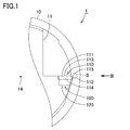
- FIG. 1 is a front view of a reamer according to the embodiment.
- FIG. 2 is an enlarged view showing a portion surrounded by II in FIG.
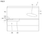
- FIG. 3 is a side view of the reamer viewed from a direction indicated by an arrow III in FIG.
- the conventional reamer has a problem that the surface roughness of the work material cannot be reduced.
- the present invention has been made to solve the above problems, and has as its object to provide a reamer that can reduce the surface roughness of a work material. [Effects of the present disclosure] According to the present invention, it is possible to provide a reamer capable of reducing the surface roughness of a work material.
- the reamer according to one aspect of the present invention includes a base metal, a plurality of outer cutting edges of a super-hard tool material provided on the outer periphery of the base metal, and a margin provided on the rotation direction rear side of the plurality of outer cutting edges.
- the distance from the rotation axis to the position of the center of gravity of the reamer is more than 0.01 mm and 0.5 mm or less.
- the better the rotational balance of the tool that is, the smaller the amount of eccentricity (the distance from the rotating shaft to the center of gravity of the reamer) is better.
- the present inventor has focused on the surface roughness of the work material, and as a result, has found that the surface roughness of the work material can be reduced by increasing the amount of eccentricity. The theory of why the surface roughness of the work material decreases when the amount of eccentricity increases is not always clear, but is estimated as follows.
- the width of the margin in the rotation direction is 0.05 mm or more and less than 0.5 mm
- the surface roughness Ra of the margin (JIS B 0601-2001) is 0.05 ⁇ m or more and less than 0.4 ⁇ m. In this case, the burnish effect by the margin is maximized, and the surface roughness of the work material is reduced.
- the angles between the plurality of outer peripheral cutting edges are different, and the difference is more than 20 °.
- the angles between the plurality of outer peripheral cutting edges are different, the plurality of cutting edges are unevenly arranged on the circumference.
- the difference between the angles exceeds 20 °, the vanish effect is further enhanced.
- FIG. 1 is a front view of the reamer according to the embodiment.
- FIG. 2 is an enlarged view showing a portion surrounded by II in FIG.
- FIG. 3 is a side view of the reamer viewed from a direction indicated by an arrow III in FIG.
- the reamer 1 as a rotary cutting tool has a base metal 10.
- the base metal 10 extends in the longitudinal direction.
- a tip 100 is provided at the tip of the base metal 10.
- the base metal 10 is provided with a flute 11 so as to extend in the longitudinal direction.
- the chip 100 is arranged in the flute 11.
- the base 10 is made of, for example, a cemented carbide.
- the chip 100 is fixed to the base metal 10 by brazing. Although the chip 100 is directly fixed to the base 10 in this embodiment, the chip 100 may be fixed to the base by brazing, and the base may be fixed to the base 10 by brazing or bolts.
- the chip 100 includes a super hard tool tip 110 made of single crystal diamond synthesized by, for example, CVD (chemical vapor deposition), and a pedestal 120 as a base for holding the super hard tool tip 110.
- the super hard tool tip 110 is not limited to a single crystal diamond, and is made of a super hard tool material such as polycrystalline diamond and cubic boron nitride (CBN).
- the base metal 10 is provided with a cutting oil passage.
- the cutting oil passage extends inside the base metal 10 along the longitudinal direction of the base metal 10 and is connected to a hole 13 for supplying the cutting oil to the contact interface between the super hard tool tip 110 and the work material. I have.
- a plurality of chips 100 are provided on the base metal 10.
- the plurality of chips 100 are provided on the same circumferential orbit. Further, a plurality of chips 100 may be provided on the base 10 over a plurality of stages in the axial direction of the base 10.
- the tip 100 has an outer peripheral cutting edge 115 and a front cutting edge 113 connected to the outer peripheral cutting edge 115.
- a cutting edge corner is formed between the outer peripheral cutting edge 115 and the front cutting edge 113.
- the portion surrounded by the outer peripheral cutting edge 115 and the front cutting edge 113 is the rake face 111.
- the front cutting edge 113 extends so as to be substantially perpendicular to the outer peripheral cutting edge 115.
- the front cutting edge 113 may have an inclination angle with respect to the outer peripheral cutting edge 115.
- the inclination angle is an angle formed by the front cutting edge 113 with respect to the radial direction.
- the ultra-hard tool tip 110 is made of single crystal diamond, it is made of single crystal diamond synthesized by CVD or single crystal diamond formed by direct synthesis using high-temperature and high-pressure conditions.
- the super-hard tool tip 110 is fixed on a base 120 made of a super-hard alloy.
- a margin 116 and an outer peripheral flank 112 are formed so as to extend along the outer peripheral cutting edge 115.
- the margin 116 is a portion that comes into contact with the work material in rotary cutting
- the outer peripheral flank 112 is a portion that does not come into contact with the work material in rotary cutting.
- the margin 116 is composed of only the super-hard tool tip 110.
- the margin 116 may be constituted by the super-hard tool tip 110 and the pedestal 120.
- the width of the margin 116 along the rotation direction is larger than the width of the super hard tool tip 110 along the rotation direction.
- a front flank 114 is formed along the front cutting edge 113.
- the outer peripheral flank 112 is formed not only on the super-hard tool tip 110 but also on a pedestal 120 of a super-hard alloy.
- the reamer 1 includes a base metal 10 and a super-hard tool tip 110 provided on the outer periphery of the base metal 10.
- the super-hard tool tip 110 is provided on the outer peripheral cutting edge 115 and on the rear side in the rotation direction of the outer peripheral cutting edge 115. And a margin 116 provided.
- the margin 116 has a curved shape.
- a ridge 116 a is formed so as to extend in a direction different from the outer peripheral cutting edge 115 and the front cutting edge 113 along a margin 116 from a cutting edge corner which is an intersection of the outer peripheral cutting edge 115 and the front cutting edge 113.
- the front cutting edge 113 protrudes from the tip 10 a of the base metal 10.
- the front cutting edge 113 does not need to protrude from the tip 10a.
- a blade angle (an angle formed by the rake face 111 and the outer flank 112 and the front flank 114) of 70 ° or more is preferable because the strength of the front cutting edge 113 and the outer cutting edge 115 increases.
- Eccentricity is measured as follows. First, attach the reamer to the high-precision tool balancer. As a high-precision tool balancer, there is a tool dynamic TD comfort manufactured by HAIMER.
- the margin 116 is a curved portion between the outer peripheral cutting edge 115 and the outer peripheral flank 112, the margin 116 has a flat surface with zero curvature (non-curved surface). ) Is measured in the rotational direction up to the outer peripheral flank 112.
- the surface roughness Ra of the margin 116 is measured by a surf test SV-3200 manufactured by Mitutoyo Corporation in accordance with JIS B 0601: 2001.
- Example 1 The base metal 10 was composed of a cemented carbide, and the ultra-hard tool tip 110 was composed of polycrystalline diamond (PCD) to produce reamers shown in Table 1.
- the eccentric amount of the reamer was adjusted by the following method. A reamer in which the super hard tool tip 110 having each cutting edge was fixed to the base metal 10 was attached to a high-precision tool balancer, and the amount of eccentricity was calculated as described above. When there is a difference between the calculated amount of eccentricity and the set value of the amount of eccentricity, in the base 10, from the end opposite to the tip 10a of the base 10 to the side opposite to the tip 10a of the base 10. The amount of eccentricity was adjusted by removing the portion located between the ends of the flutes 11 located.
- PCD polycrystalline diamond
- Example 2 The base metal 10 was composed of a cemented carbide, and the ultra-hard tool tip 110 was composed of polycrystalline diamond (PCD) to produce reamers shown in Table 2. Cutting evaluation was performed under the following conditions.
- PCD polycrystalline diamond
- Example 3 The base metal 10 was composed of a cemented carbide, and the ultra-hard tool tip 110 was composed of polycrystalline diamond (PCD). Cutting evaluation was performed under the following conditions.
- Example 4 The base metal 10 was composed of a cemented carbide, and the ultra-hard tool tip 110 was composed of a polycrystalline CBN sintered body (PcBN), and reamers shown in Table 4 were produced. Cutting evaluation was performed under the following conditions.
- Table 4 shows that the sample having an eccentricity of 0.01 mm or less and the sample having an eccentricity of more than 0.5 mm are evaluated as B because the surface roughness Rz of the work material after processing is large.
- Example 5 The base metal 10 was composed of a cemented carbide, and the ultra-hard tool tip 110 was composed of polycrystalline CBN (PcBN), and reamers shown in Table 5 were produced. Cutting evaluation was performed under the following conditions.
- Example 6 The base metal 10 was composed of a cemented carbide, and the ultra-hard tool tip 110 was composed of polycrystalline CBN (PcBN), and reamers shown in Table 6 were produced. Cutting evaluation was performed under the following conditions.
- the vibration suppressing effect works and the surface roughness is improved.
- the vibration suppressing effect is enhanced.
Landscapes
- Engineering & Computer Science (AREA)
- Mechanical Engineering (AREA)
- Milling, Broaching, Filing, Reaming, And Others (AREA)
Abstract
L'invention concerne un alésoir pourvu d'un métal de base, d'une pluralité de bords de coupe de circonférence externe constitués d'un matériau d'outil super-dur et disposés sur la circonférence externe du métal de base, et des marges disposées sur le côté arrière de la pluralité de bords de coupe de circonférence externe dans la direction de rotation. La distance de l'axe de rotation au centre de gravité de l'alésoir est supérieure à 0,01 mm et inférieure à 0,5 mm.
Priority Applications (4)
| Application Number | Priority Date | Filing Date | Title |
|---|---|---|---|
| US16/973,612 US11407047B2 (en) | 2018-06-28 | 2019-04-03 | Reamer |
| CN201980043587.5A CN112351853B (zh) | 2018-06-28 | 2019-04-03 | 铰刀 |
| MX2020013106A MX2020013106A (es) | 2018-06-28 | 2019-04-03 | Escariador. |
| JP2019551412A JP6670422B1 (ja) | 2018-06-28 | 2019-04-03 | リーマ |
Applications Claiming Priority (2)
| Application Number | Priority Date | Filing Date | Title |
|---|---|---|---|
| JP2018123496 | 2018-06-28 | ||
| JP2018-123496 | 2018-06-28 |
Publications (1)
| Publication Number | Publication Date |
|---|---|
| WO2020003680A1 true WO2020003680A1 (fr) | 2020-01-02 |
Family
ID=68986981
Family Applications (1)
| Application Number | Title | Priority Date | Filing Date |
|---|---|---|---|
| PCT/JP2019/014773 Ceased WO2020003680A1 (fr) | 2018-06-28 | 2019-04-03 | Alésoir |
Country Status (5)
| Country | Link |
|---|---|
| US (1) | US11407047B2 (fr) |
| JP (1) | JP6670422B1 (fr) |
| CN (1) | CN112351853B (fr) |
| MX (1) | MX2020013106A (fr) |
| WO (1) | WO2020003680A1 (fr) |
Citations (9)
| Publication number | Priority date | Publication date | Assignee | Title |
|---|---|---|---|---|
| JP2001079706A (ja) * | 1999-09-07 | 2001-03-27 | Sumitomo Electric Ind Ltd | ガイドパッド付き回転切削工具 |
| JP2005022064A (ja) * | 2003-07-03 | 2005-01-27 | Tungaloy Corp | 被覆穴あけ工具 |
| JP2005193349A (ja) * | 2004-01-09 | 2005-07-21 | Tungaloy Corp | 穴あけ工具 |
| JP2010125532A (ja) * | 2008-11-25 | 2010-06-10 | Allied Material Corp | リーマ |
| JP2011062790A (ja) * | 2009-09-18 | 2011-03-31 | Allied Material Corp | 回転切削工具 |
| CN202344044U (zh) * | 2011-11-30 | 2012-07-25 | 深圳市中天精密工具有限公司 | 一种用于加工孔的铰刀 |
| JP2017052081A (ja) * | 2015-09-09 | 2017-03-16 | 三菱マテリアル株式会社 | ドリル |
| JP2017087373A (ja) * | 2015-11-13 | 2017-05-25 | 株式会社アライドマテリアル | 回転切削工具 |
| JP2019063977A (ja) * | 2017-09-28 | 2019-04-25 | 株式会社タンガロイ | リーマ |
Family Cites Families (21)
| Publication number | Priority date | Publication date | Assignee | Title |
|---|---|---|---|---|
| GB1208127A (en) * | 1967-11-29 | 1970-10-07 | Inst Burovoi Tekhnik | Improvements in or relating to well reamers |
| JPH09136209A (ja) * | 1995-11-16 | 1997-05-27 | Yutaka Giken Co Ltd | エンドミル |
| DE19621295C2 (de) * | 1996-05-25 | 1998-08-27 | Mapal Fab Praezision | Reibahle für die spanabhebende Feinbearbeitung |
| JPH10263929A (ja) * | 1997-03-18 | 1998-10-06 | Toshiba Tungaloy Co Ltd | ガンリーマ |
| US6269893B1 (en) * | 1999-06-30 | 2001-08-07 | Smith International, Inc. | Bi-centered drill bit having improved drilling stability mud hydraulics and resistance to cutter damage |
| US6379090B1 (en) * | 2000-06-30 | 2002-04-30 | The Boeing Company | Force balanced irregular pitch reamer and associated reaming method |
| TWI262114B (en) * | 2002-09-05 | 2006-09-21 | Nitto Kohki Co | O-shaped blade |
| JP2006088242A (ja) | 2004-09-22 | 2006-04-06 | Asahi Diamond Industrial Co Ltd | 穴明け工具 |
| JP4917471B2 (ja) * | 2007-04-02 | 2012-04-18 | ユニタック株式会社 | 深穴切削装置 |
| AU2012318698B2 (en) * | 2011-10-03 | 2016-05-12 | Extreme Technologies, Llc | Wellbore conditioning system |
| CN103128373B (zh) * | 2011-11-30 | 2015-09-30 | 深圳市中天超硬工具股份有限公司 | 用于加工孔壁非连续的孔的聚晶金刚石铰刀 |
| FR2991209B1 (fr) * | 2012-06-05 | 2015-07-03 | Snecma | Tete de calibrage pour le forage d’arbres |
| WO2014050884A1 (fr) * | 2012-09-28 | 2014-04-03 | 株式会社アライドマテリアル | Lame coupante du type lame plate et lame coupante pour feuille crue |
| WO2015026955A1 (fr) * | 2013-08-21 | 2015-02-26 | Scianamblo Michael J | Perçage et alésage avec précession |
| JP5925250B2 (ja) * | 2014-07-07 | 2016-05-25 | ユニオンツール株式会社 | スクエアエンドミル |
| JP2016032863A (ja) | 2014-07-29 | 2016-03-10 | 株式会社アライドマテリアル | 回転切削工具および被加工物の製造方法 |
| JP5980360B1 (ja) * | 2015-02-27 | 2016-08-31 | 株式会社牧野フライス製作所 | フライス工具 |
| CN206104913U (zh) * | 2016-10-10 | 2017-04-19 | 上海泰锋精密刀具股份有限公司 | 一种整体硬质合金镗铰复合刀 |
| DE102017208017B4 (de) * | 2017-05-11 | 2019-02-21 | MAPAL Fabrik für Präzisionswerkzeuge Dr. Kress KG | Mehrschneidige Reibahle |
| JP6838164B2 (ja) * | 2017-08-30 | 2021-03-03 | 株式会社イシイコーポレーション | テーパーリーマ |
| JP6697131B1 (ja) * | 2018-06-28 | 2020-05-20 | 株式会社アライドマテリアル | リーマ |
-
2019
- 2019-04-03 WO PCT/JP2019/014773 patent/WO2020003680A1/fr not_active Ceased
- 2019-04-03 MX MX2020013106A patent/MX2020013106A/es unknown
- 2019-04-03 CN CN201980043587.5A patent/CN112351853B/zh active Active
- 2019-04-03 US US16/973,612 patent/US11407047B2/en active Active
- 2019-04-03 JP JP2019551412A patent/JP6670422B1/ja active Active
Patent Citations (9)
| Publication number | Priority date | Publication date | Assignee | Title |
|---|---|---|---|---|
| JP2001079706A (ja) * | 1999-09-07 | 2001-03-27 | Sumitomo Electric Ind Ltd | ガイドパッド付き回転切削工具 |
| JP2005022064A (ja) * | 2003-07-03 | 2005-01-27 | Tungaloy Corp | 被覆穴あけ工具 |
| JP2005193349A (ja) * | 2004-01-09 | 2005-07-21 | Tungaloy Corp | 穴あけ工具 |
| JP2010125532A (ja) * | 2008-11-25 | 2010-06-10 | Allied Material Corp | リーマ |
| JP2011062790A (ja) * | 2009-09-18 | 2011-03-31 | Allied Material Corp | 回転切削工具 |
| CN202344044U (zh) * | 2011-11-30 | 2012-07-25 | 深圳市中天精密工具有限公司 | 一种用于加工孔的铰刀 |
| JP2017052081A (ja) * | 2015-09-09 | 2017-03-16 | 三菱マテリアル株式会社 | ドリル |
| JP2017087373A (ja) * | 2015-11-13 | 2017-05-25 | 株式会社アライドマテリアル | 回転切削工具 |
| JP2019063977A (ja) * | 2017-09-28 | 2019-04-25 | 株式会社タンガロイ | リーマ |
Also Published As
| Publication number | Publication date |
|---|---|
| JPWO2020003680A1 (ja) | 2020-07-09 |
| CN112351853B (zh) | 2023-10-03 |
| US11407047B2 (en) | 2022-08-09 |
| JP6670422B1 (ja) | 2020-03-18 |
| CN112351853A (zh) | 2021-02-09 |
| US20210245277A1 (en) | 2021-08-12 |
| MX2020013106A (es) | 2021-02-17 |
Similar Documents
| Publication | Publication Date | Title |
|---|---|---|
| JP5470478B2 (ja) | 正面フライス | |
| KR20010082729A (ko) | 볼엔드밀 | |
| CN102791408A (zh) | 端面铣刀及其应用 | |
| CN108290233B (zh) | 可转位刀片式旋转切削工具及刀片 | |
| RU2007147659A (ru) | Режущая вставка для инструмента, в частности фрезы и фреза | |
| JP6670422B1 (ja) | リーマ | |
| JP2016117113A (ja) | フライス工具、及びこれを用いた加工方法 | |
| JP2016032863A (ja) | 回転切削工具および被加工物の製造方法 | |
| JP6697131B1 (ja) | リーマ | |
| JP2002254233A (ja) | 正面フライス用のサライ刃チップ | |
| JP2009083078A (ja) | リーマ | |
| Wang et al. | Study on cutting force and hole quality of PCD step reamer for reaming ZL102 alloy in dry and wet conditions | |
| JP2526707Y2 (ja) | 回転切削工具 | |
| US20240375191A1 (en) | Drill | |
| JP2003039220A (ja) | 穴明け工具 | |
| JP2003136317A (ja) | ドリル | |
| JPH04201102A (ja) | ダイヤモンド被覆スローアウェイチップ | |
| JP2000117523A (ja) | ダイヤモンドコーティングエンドミル又はドリル並びに切削法 | |
| JP6626853B2 (ja) | 回転切削工具 | |
| JP2001079706A (ja) | ガイドパッド付き回転切削工具 | |
| JP2016117111A (ja) | 回転切削工具 | |
| JP2505803B2 (ja) | エンドミル | |
| JP3032863B2 (ja) | ドリル | |
| WO2021075216A1 (fr) | Outil de coupe rotatif | |
| JPH07195222A (ja) | 荒加工用エンドミル |
Legal Events
| Date | Code | Title | Description |
|---|---|---|---|
| ENP | Entry into the national phase |
Ref document number: 2019551412 Country of ref document: JP Kind code of ref document: A |
|
| 121 | Ep: the epo has been informed by wipo that ep was designated in this application |
Ref document number: 19825936 Country of ref document: EP Kind code of ref document: A1 |
|
| NENP | Non-entry into the national phase |
Ref country code: DE |
|
| 122 | Ep: pct application non-entry in european phase |
Ref document number: 19825936 Country of ref document: EP Kind code of ref document: A1 |