WO2020003694A1 - 生体貼り付け電極、及び、生体貼り付け電極の製造方法 - Google Patents
生体貼り付け電極、及び、生体貼り付け電極の製造方法 Download PDFInfo
- Publication number
- WO2020003694A1 WO2020003694A1 PCT/JP2019/015778 JP2019015778W WO2020003694A1 WO 2020003694 A1 WO2020003694 A1 WO 2020003694A1 JP 2019015778 W JP2019015778 W JP 2019015778W WO 2020003694 A1 WO2020003694 A1 WO 2020003694A1
- Authority
- WO
- WIPO (PCT)
- Prior art keywords
- electrode
- living body
- elastic substrate
- gel
- main surface
- Prior art date
- Legal status (The legal status is an assumption and is not a legal conclusion. Google has not performed a legal analysis and makes no representation as to the accuracy of the status listed.)
- Ceased
Links
Images



Classifications
-
- A—HUMAN NECESSITIES
- A61—MEDICAL OR VETERINARY SCIENCE; HYGIENE
- A61B—DIAGNOSIS; SURGERY; IDENTIFICATION
- A61B5/00—Measuring for diagnostic purposes; Identification of persons
- A61B5/68—Arrangements of detecting, measuring or recording means, e.g. sensors, in relation to patient
- A61B5/6801—Arrangements of detecting, measuring or recording means, e.g. sensors, in relation to patient specially adapted to be attached to or worn on the body surface
- A61B5/683—Means for maintaining contact with the body
- A61B5/6832—Means for maintaining contact with the body using adhesives
- A61B5/6833—Adhesive patches
-
- H—ELECTRICITY
- H05—ELECTRIC TECHNIQUES NOT OTHERWISE PROVIDED FOR
- H05K—PRINTED CIRCUITS; CASINGS OR CONSTRUCTIONAL DETAILS OF ELECTRIC APPARATUS; MANUFACTURE OF ASSEMBLAGES OF ELECTRICAL COMPONENTS
- H05K1/00—Printed circuits
- H05K1/02—Details
-
- A—HUMAN NECESSITIES
- A61—MEDICAL OR VETERINARY SCIENCE; HYGIENE
- A61B—DIAGNOSIS; SURGERY; IDENTIFICATION
- A61B2562/00—Details of sensors; Constructional details of sensor housings or probes; Accessories for sensors
- A61B2562/12—Manufacturing methods specially adapted for producing sensors for in-vivo measurements
- A61B2562/125—Manufacturing methods specially adapted for producing sensors for in-vivo measurements characterised by the manufacture of electrodes
-
- A—HUMAN NECESSITIES
- A61—MEDICAL OR VETERINARY SCIENCE; HYGIENE
- A61B—DIAGNOSIS; SURGERY; IDENTIFICATION
- A61B2562/00—Details of sensors; Constructional details of sensor housings or probes; Accessories for sensors
- A61B2562/16—Details of sensor housings or probes; Details of structural supports for sensors
- A61B2562/164—Details of sensor housings or probes; Details of structural supports for sensors the sensor is mounted in or on a conformable substrate or carrier
-
- H—ELECTRICITY
- H01—ELECTRIC ELEMENTS
- H01B—CABLES; CONDUCTORS; INSULATORS; SELECTION OF MATERIALS FOR THEIR CONDUCTIVE, INSULATING OR DIELECTRIC PROPERTIES
- H01B5/00—Non-insulated conductors or conductive bodies characterised by their form
- H01B5/14—Non-insulated conductors or conductive bodies characterised by their form comprising conductive layers or films on insulating-supports
Definitions
- the present invention relates to a living body-attached electrode and a method of manufacturing the living body-attached electrode.
- Patent Literature 1 a living body-attached electrode in which an electrode part and a wiring part are formed on a stretchable base material and biological information is obtained via a biogel provided on the surface of the electrode part It has been known.
- a bio-gel (hereinafter, referred to as a gel electrode) may cause lateral displacement.
- the electrode portion or the wiring portion formed on the elastic substrate is exposed and comes into contact with the living body. Since a material having no biocompatibility is often used for the electrode portion and the wiring portion, it is desirable that the electrode portion and the wiring portion do not contact the living body as much as possible.
- the present invention has been made in order to solve the above-described problem, and it is an object of the present invention to provide a living body-attached electrode that prevents exposure of an electrode portion or a wiring portion with respect to lateral displacement of a gel electrode and can avoid contact with a living body. Aim. Another object of the present invention is to provide a method for producing the above-mentioned living body-adhered electrode.
- the living body-attached electrode of the present invention includes a first stretchable base material, an electrode portion provided on one main surface of the first stretchable base material, and a wiring portion connected to the electrode portion.
- a conductive pattern, and a second pattern provided on one main surface of the first stretchable base material so as to cover at least the wiring portion of the conductive pattern, and having an opening exposing at least a part of the electrode portion.
- a gel electrode provided in the opening of the second stretchable base material and connected to the electrode portion, wherein the gel electrode is provided in the opening of the second stretchable base material.
- the main surface of the second elastic substrate is also provided on the main surface of the second elastic substrate that is not in contact with the first elastic substrate so as to spread outward.
- the method for producing a living body-attached electrode according to the present invention includes the steps of: forming a conductive pattern including an electrode portion and a wiring portion connected to the electrode portion on one main surface of the first stretchable base; Disposing a second stretchable base material on one main surface of the first stretchable base material, covering at least the wiring portion of the conductive pattern with the second stretchable base material, Exposing at least a part of the electrode portion from the opening of the second elastic substrate, applying a gel electrode material into the opening of the second elastic substrate, and curing the gel electrode material Forming a gel electrode that is electrically connected to the electrode section.
- organism sticking electrode which can prevent exposure of an electrode part or a wiring part with respect to the lateral displacement of a gel electrode and can avoid contact with a living body can be provided.
- FIG. 1 is a cross-sectional view schematically showing a living body stuck electrode according to the first embodiment of the present invention.
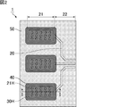
- FIG. 2 is a top view schematically illustrating the living body-attached electrode according to the first embodiment of the present invention.
- FIG. 3 is a cross-sectional view schematically showing an example of a state in which the living body-attached electrode shown in FIG. 1 is attached to a human body.
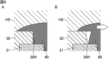
- FIGS. 4A and 4B are cross-sectional views schematically illustrating an example of a state in which the gel electrode provided to the outside of the opening of the second stretchable base material has shifted laterally.
- FIGS. 1 is a cross-sectional view schematically showing a living body stuck electrode according to the first embodiment of the present invention.
- FIG. 2 is a top view schematically illustrating the living body-attached electrode according to the first embodiment of the present invention.
- FIG. 3 is a cross-sectional view schematically showing an example of a state in which the living body-attached
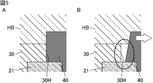
- FIG. 5A and 5B are cross-sectional views schematically illustrating an example of a state in which a gel electrode that is not provided outside the opening of the second stretchable base material has shifted laterally.
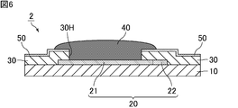
- FIG. 6 is a cross-sectional view schematically illustrating a living body stuck electrode according to the second embodiment of the present invention.
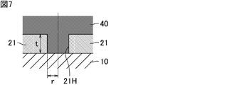
- FIG. 7 is a cross-sectional view showing the relationship between the radius of the through hole of the electrode part and the thickness of the electrode part.
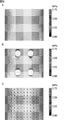
- 8A, 8B, and 8C are distribution diagrams of the shearing force on the upper surface of the electrode unit obtained by the simulation.
- FIG. 9 is a cross-sectional view schematically showing a living body stuck electrode according to the third embodiment of the present invention.
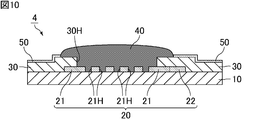
- FIGS. 10 is a cross-sectional view schematically showing a living body stuck electrode according to a fourth embodiment of the present invention.
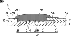
- FIG. 11 is a cross-sectional view schematically showing a living body stuck electrode according to the fifth embodiment of the present invention.
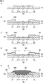
- FIGS. 12A, 12B, 12C, 12D, and 12E are cross-sectional views schematically showing a method of manufacturing a living body-attached electrode according to the first embodiment of the present invention.
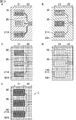
- FIGS. 13A, 13B, 13C, 13D, and 13E are top views schematically showing a method of manufacturing a living body-attached electrode according to the first embodiment of the present invention.
- the living body stuck electrode of the present invention will be described.
- the present invention is not limited to the following configuration, and can be appropriately modified and applied without changing the gist of the present invention. It should be noted that a combination of two or more of the individual desirable configurations of the present invention described below is also the present invention.
- FIG. 1 is a cross-sectional view schematically showing a living body stuck electrode according to the first embodiment of the present invention.
- FIG. 2 is a top view schematically illustrating the living body-attached electrode according to the first embodiment of the present invention.
- FIG. 1 is a cross-sectional view taken along the line II of the living body stuck electrode shown in FIG. In FIG. 2, the conductive pattern is shown as being transparent.
- the living body-adhered electrode 1 includes an adhesive layer 50 on a main surface of the second elastic substrate 30 that is not in contact with the first elastic substrate 10. Further, it is desirable to provide.
- the conductive pattern 20 is provided on one main surface of the first stretchable base material 10 and includes an electrode portion 21 and a wiring portion 22 connected to the electrode portion 21.
- the electrode portion 21 has a plurality of through holes 21H penetrating in the thickness direction (vertical direction in FIG. 1).
- the electrode portion 21 may have a plurality of recesses that are recessed in the thickness direction from a main surface that is not in contact with the first elastic substrate 10 instead of the through-hole 21H.
- the second elastic substrate 30 is provided on one main surface of the first elastic substrate 10 so as to cover at least the wiring portion 22 of the conductive pattern 20, and at least a part of the electrode portion 21. Is provided. In the living body stuck electrode 1, in addition to the wiring portion 22, the entire periphery of the electrode portion 21 is covered with the second elastic base material 30 (see FIG. 13B).
- the gel electrode 40 is provided in the opening 30 ⁇ / b> H of the second stretchable base material 30 and is electrically connected to the electrode unit 21. In the living body stuck electrode 1, the gel electrode 40 also enters the through hole 21H of the electrode portion 21.
- the gel electrode 40 is in contact with the first elastic substrate 10 of the main surface of the second elastic substrate 30 so as to spread outside the opening 30H of the second elastic substrate 30. Not even on the main surface.
- FIG. 3 is a cross-sectional view schematically showing an example of a state in which the living body-attached electrode shown in FIG. 1 is attached to a human body.
- the living body pasting electrode 1 can measure a biological signal through the gel electrode 40.
- FIGS. 4A and 4B are cross-sectional views schematically illustrating an example of a state in which the gel electrode provided to the outside of the opening of the second stretchable base material has shifted laterally.
- FIG. 4A shows the X region in FIG. 3 in an enlarged manner.
- the adhesive layer 50 is omitted.
- the first stretchable base material 10 and the second stretchable base material 30 are extended with the movement of the human body HB in the direction of the arrow shown in FIG. 3, the gel is moved in the direction of the arrow shown in FIG. 4B.
- the electrode 40 may cause a lateral displacement.
- FIGS. 5A and 5B are cross-sectional views schematically illustrating an example of a state in which a gel electrode that is not provided outside the opening of the second stretchable base material has shifted laterally. If the gel electrode 40 is not provided to the outside of the opening 30H of the second stretchable base material 30 as shown in FIG. 5A, and the gel electrode 40 laterally shifts in the direction of the arrow shown in FIG. A gap is formed between the second stretchable base material 30 and the gel electrode 40 in the direction of the main surface as surrounded by a circle, and the electrode portion 21 is exposed.
- the skin of the human body HB may enter the gap between the second elastic base material 30 and the gel electrode 40 and come into contact with the electrode portion 21. There is. In addition, there is a possibility that the components of the electrode portion 21 may be eluted by the water coming out of the human body HB and come into contact with the human body HB.
- the gel electrode is provided to the outside of the opening of the second stretchable base material, the electrode portion or the wiring portion is exposed to the lateral displacement of the gel electrode. Can be prevented, and contact with a living body such as a human body can be avoided.
- the wiring portion can be sealed while having an elastic function.
- the first elastic substrate and the second elastic substrate are made of, for example, a resin material having elasticity.
- the resin material constituting the first stretchable base material and the second stretchable base material include thermoplastic polyurethane.
- the material forming the first stretchable base material may be the same as or different from the material forming the second stretchable base material.
- the thicknesses of the first stretchable base material and the second stretchable base material are not particularly limited. , 100 ⁇ m or less, and more preferably 1 ⁇ m or less. Further, the thickness of each of the first elastic substrate and the second elastic substrate is preferably 0.1 ⁇ m or more. The thickness of the first stretchable substrate may be the same as or different from the thickness of the second stretchable substrate.
- the electrode portion and the wiring portion constituting the conductive pattern are formed of a conductive material.
- the conductive material forming the electrode portion and the wiring portion include a mixture of metal particles such as silver and copper and an elastomer resin such as silicone.
- the conductive material forming the electrode portion may be the same as or different from the conductive material forming the wiring portion.
- the thickness of the electrode portion and the wiring portion constituting the conductive pattern is not particularly limited, but is preferably 100 ⁇ m or less, and more preferably 50 ⁇ m or less. Further, the thickness of each of the electrode portion and the wiring portion is desirably 1 ⁇ m or more. The thickness of the electrode portion may be the same as or different from the thickness of the wiring portion.
- the first stretchable base material and the second stretchable base material may be thinner or thicker than the electrode portion and the wiring portion. This is desirable because the elasticity of the material can be improved.
- the gel electrode is made of a conductive gel material including, for example, water, alcohol, humectant, electrolyte, and the like.
- a conductive gel material including, for example, water, alcohol, humectant, electrolyte, and the like.
- examples of such a gel material include hydrogel.
- the gel electrode is desirably formed by applying a gel electrode material into the opening of the second stretchable base material and curing the gel electrode material.
- a core material for maintaining the shape of the gel electrode is used. It does not have to be used.
- Such a core material is composed of a nonwoven fabric or a woven fabric. Examples of the material constituting the nonwoven fabric or woven fabric include natural fibers such as cellulose, silk, and hemp; synthetic fibers such as polyester, nylon, rayon, polyethylene, polypropylene, and polyurethane;
- the content of the core material in the gel electrode is preferably 50% by weight or less, more preferably 10% by weight or less, and the detection limit or less. Is particularly desirable.
- the content of the core material in the gel electrode is a value measured using a minute balance or the like.
- the length of the gel electrode protruding from the opening of the second elastic substrate onto the main surface of the second elastic substrate is not particularly limited, but is 1 ⁇ m or more. Is desirably 1 mm or more. Further, it is desirable that the length of the gel electrode protruding from the opening of the second elastic base material onto the main surface of the second elastic base material is 50 mm or less.
- the gel electrode provided outside the opening of the second elastic substrate protrudes in the thickness direction from the second elastic substrate.
- the gel electrode provided in the opening of the second elastic substrate does not have to protrude in the thickness direction from the second elastic substrate, but as shown in FIG. Desirably, it protrudes from the elastic substrate in the thickness direction.
- the gel electrode desirably has a convex shape that becomes thicker from the periphery to the center.
- the interface resistance between the gel electrode and the living body can be reduced.
- the gel electrode having the convex shape protrudes, a gap is generated between the periphery of the gel electrode and the human body, so that the spread of the gel electrode pressed against the human body by pasting moves to the gap.
- the spread of the gel electrode in the planar direction can be suppressed as compared with the case where the flat gel electrode protrudes. As a result, a short circuit between adjacent gel electrodes can be prevented.
- the amount of gel electrodes used can be reduced, material costs can be reduced.
- the height of the gel electrode protruding from the second elastic substrate in the thickness direction is not particularly limited, but is preferably 1 ⁇ m or more, and more preferably 100 ⁇ m or more. .
- the height of the gel electrode protruding in the thickness direction from the second elastic substrate is preferably 1 mm or less.
- FIG. 6 is a cross-sectional view schematically illustrating a living body stuck electrode according to the second embodiment of the present invention.
- the living body stuck electrode 2 shown in FIG. 6 has the same configuration as the living body stuck electrode 1 shown in FIG. 1 except that the electrode portion 21 does not have the through hole 21H.
- the electrode portion does not have to have a through hole penetrating the electrode portion in the thickness direction, but is in contact with the first elastic base material. It is desirable to have a plurality of recesses that are recessed in the thickness direction from the main surface that is not present. As shown in FIGS. 1 and 2, the recess is preferably a through hole penetrating the electrode portion in the thickness direction.
- the gel electrode enters into a concave portion such as a through-hole, and the gel electrode hardly shifts from the electrode portion due to the anchor effect. Therefore, when the gel electrode is attached to the living body, the shearing force between the gel electrode and the electrode portion caused by expansion and contraction on the living body side can be reduced.
- FIG. 7 is a cross-sectional view showing the relationship between the radius of the through hole of the electrode part and the thickness of the electrode part.
- the radius of the through hole 21H of the electrode portion 21 is r and the thickness of the electrode portion 21 is t
- the area of the gel electrode 40 in contact with the electrode portion 21 is smaller than that of the state without the through hole 21H.
- r 2 is the bottom area of the increases by 2 ⁇ rt a side area of the through hole 21H. Therefore, 0 ⁇ 2 ⁇ rt- ⁇ r 2 i.e. in the case of r ⁇ 2t, without gel electrode 40 reduces the area of contact with the electrode portion 21 in comparison with the situation that there is the through hole 21H, a gel electrode 40 and the electrode portion 21 can be reduced.
- r ⁇ 2t, where r is the radius of the through hole of the electrode portion and t is the thickness of the electrode portion.
- the present inventors have confirmed the shear force between the gel electrode 40 and the electrode unit 21 generated by the movement of the human body HB in the direction of the arrow shown in FIG. 3 by using a simulation.
- FIGS. 8B and 8C are distribution diagrams of the shearing force on the upper surface of the electrode unit obtained by the simulation.
- FIG. 8A shows the distribution of the shearing force when the electrode portion has no through hole
- FIGS. 8B and 8C show the distribution of the shearing force when the electrode portion has the through hole.
- the thickness t of the electrode portion is 15 ⁇ m.
- the shearing force is generally lower in FIG. 8B in which the electrode portion has no through hole.
- the shearing force is intensively reduced. Therefore, it is considered that the provision of the through-hole in the electrode portion can reduce the shearing force between the gel electrode and the electrode portion.
- the electrode portion has a plurality of concave portions in the living body stuck electrode of the present invention
- all of the concave portions may have the same shape or at least a part thereof may be different.
- the electrode portion may have both the concave portion and the through hole.
- FIG. 9 is a cross-sectional view schematically showing a living body stuck electrode according to the third embodiment of the present invention. 9 is shown in FIG. 1 except that a portion of the periphery of the electrode portion 21 that is not connected to the wiring portion 22 is not covered with the second elastic base material 30. It has the same configuration as the living body stuck electrode 1.
- the living body-attached electrode 2 shown in FIG. 6 as well as in the living body-attached electrode 1 shown in FIG. 1, a portion of the periphery of the electrode portion 21 that is not connected to the wiring portion 22 is the second elastic base material 30. It does not need to be covered with.
- the wiring portion of the conductive pattern only needs to be covered with the second elastic base material, and as shown in FIG. It may be covered with a stretchable base material, or, as shown in FIG. 9, a portion of the periphery of the electrode portion that is not connected to the wiring portion may not be covered with the second stretchable base material. .
- the electrode portion is exposed from the opening of the second elastic substrate. Therefore, as shown in FIG. 1, a part of the electrode portion may be exposed from the opening of the second elastic substrate, or the entire electrode portion may be exposed from the opening of the second elastic substrate. May be.
- the entirety of the electrode portion is exposed from the opening of the second stretchable base material, only the wiring portion of the conductive pattern is covered with the second stretchable base material, and the electrode portion has the second stretchability. Not covered by substrate.
- the living body-adhered electrode of the present invention may further include an adhesive layer on a main surface of the second elastic substrate that is not in contact with the first elastic substrate. desirable. By providing an adhesive layer on the main surface of the second stretchable base material, the adhesiveness to a living body can be improved.
- FIG. 10 is a cross-sectional view schematically showing a living body stuck electrode according to a fourth embodiment of the present invention.
- the adhesive layer 50 is formed between the gel electrode 40 and the main surface of the second elastic substrate 30 that is not in contact with the first elastic substrate 10. Except that it is not provided, it has the same configuration as the living body stuck electrode 1 shown in FIG. Not only the living body-attached electrode 1 shown in FIG. 1 but also the living body-attached electrode 2 shown in FIG. 6 and the living body-attached electrode 3 shown in FIG.
- the adhesive layer 50 may not be provided between the main surface not in contact with the first elastic substrate 10 and the gel electrode 40.
- the adhesive layer is, as shown in FIG. 10, a main surface of the second elastic substrate that is not in contact with the first elastic substrate. Although it may not be provided between the first stretchable base material and the gel surface, as shown in FIG. It is desirable to be provided between the electrodes. In this case, the adhesive layer is hardly peeled off from the second stretchable base material, and the gel electrode is hardly laterally shifted. Therefore, exposure of the electrode portion or the wiring portion can be further prevented.
- the adhesive layer is made of, for example, an adhesive resin such as an acrylic polymer or a urethane resin.
- the thickness of the adhesive layer is not particularly limited, but is preferably 10 ⁇ m or less, more preferably 1 ⁇ m or less. Further, the thickness of the adhesive layer is desirably 0.1 ⁇ m or more.
- the living body-attached electrode of the present invention may not include the adhesive layer.
- FIG. 11 is a cross-sectional view schematically showing a living body stuck electrode according to the fifth embodiment of the present invention.
- the living body stuck electrode 5 shown in FIG. 11 has a concave portion 30X on a main surface of the second elastic substrate 30 that is not in contact with the first elastic substrate 10. Except that the gel electrode 40 is embedded, it has the same configuration as the living body stuck electrode 3 shown in FIG. Not only the living body stuck electrode 3 shown in FIG. 9 but also the living body stuck electrode 1 shown in FIG. 1, the living body stuck electrode 2 shown in FIG. 6, and the living body stuck electrode 4 shown in FIG.
- a concave portion 30X may be provided on a main surface of the elastic substrate 30 that is not in contact with the first elastic substrate 10, and the gel electrode 40 may be embedded in the concave portion 30X.
- a concave portion is provided on a main surface of the second elastic substrate that is not in contact with the first elastic substrate, It is desirable that a gel electrode is embedded in the recess.
- the gel electrode When the gel electrode is embedded in the concave portion provided on the main surface of the second stretchable base material, the gel electrode has a structure that is difficult to peel off due to the anchor effect.
- the width of the concave portion is not particularly limited, but is preferably 1 ⁇ m or more and 100 ⁇ m or less.
- the depth of the concave portion is not particularly limited, but is preferably 1% or more and 75% or less of the thickness of the second stretchable base material, for example, 1 ⁇ m or more and 30 ⁇ m or less.
- the gel electrode when the gel electrode is embedded in the concave portion, the gel electrode may be embedded in the entire concave portion, or the gel electrode may be embedded in a part of the concave portion. .
- a method for producing a living body-attached electrode of the present invention will be described.
- a method for manufacturing the living body stuck electrode 1 shown in FIG. 1 will be described.
- FIGS. 12A, 12B, 12C, 12D, and 12E are cross-sectional views schematically showing a method of manufacturing a living body-attached electrode according to the first embodiment of the present invention.
- FIGS. 13A, 13B, 13C, 13D, and 13E are top views schematically showing a method of manufacturing a living body-attached electrode according to the first embodiment of the present invention.
- a conductive pattern 20 including an electrode portion 21 and a wiring portion 22 connected to the electrode portion 21 is formed on one main surface of the first elastic base material 10. I do. 12A and 13A, the electrode portion 21 forms a conductive pattern 20 having a through hole 21H.
- a conductive pattern is formed by printing a conductive paste in a predetermined pattern on one main surface of the first stretchable base material.
- the electrode portion and the wiring portion are preferably formed in the same process using the same conductive paste, but may be formed in separate processes using the same or different conductive pastes.
- the second elastic substrate 30 having the opening 30H is arranged on one main surface of the first elastic substrate 10.
- at least the wiring portion 22 of the conductive pattern 20 is covered with the second elastic substrate 30, and at least a part of the electrode portion 21 is exposed from the opening 30 ⁇ / b> H of the second elastic substrate 30.
- the entire periphery of the electrode part 21 is also covered with the second elastic base material 30.
- first elastic substrate and the second elastic substrate are thermocompression-bonded, so that the first elastic substrate is bonded to the second elastic substrate.
- the main surface of the second elastic base material 30 that is not in contact with the first elastic base material 10 is used.
- An adhesive layer 50 is formed on the surface.
- the adhesive layer is formed by applying an adhesive resin to the main surface of the second stretchable base material and then drying and / or curing the adhesive resin.
- the second stretchable base material having the adhesive layer formed thereon is replaced with the first stretchable base material. You may arrange
- the gel electrode material 140 is applied to the inside of the opening 30H of the second elastic base material 30.
- the gel electrode material When applying the gel electrode material into the opening of the second elastic substrate, the gel electrode material protrudes from the opening and is in contact with the first elastic substrate of the main surface of the second elastic substrate.
- the gel electrode material also adheres to the non-main surface.
- the gel electrode material in the opening protrudes from the second stretchable base material in the thickness direction due to surface tension.
- the gel electrode material has a convex shape that becomes thicker from the periphery toward the center.
- Examples of the method for applying the gel electrode material include a dispense method and an ink-jet method. In particular, it is desirable to apply the gel electrode material by a dispense method.
- the gel electrode material 140 is cured to form the gel electrode 40 that is electrically connected to the electrode unit 21.
- Examples of a method for curing the gel electrode material include ultraviolet curing (UV curing).
- the living body-attached electrode 1 shown in FIG. 1 is obtained.
- the gel electrode 40 extends not only in the opening 30H of the second elastic substrate 30 but also outside the opening 30H of the second elastic substrate 30,
- the main surface of the second elastic substrate 30 is also formed on the main surface that is not in contact with the first elastic substrate 10.
- the adhesive layer is formed after the gel electrode is formed, the living body stuck electrode 4 shown in FIG. 10 is obtained.
- the gel electrode is formed after forming the concave portion 30 ⁇ / b> X on the main surface of the second elastic substrate 30 that is not in contact with the first elastic substrate 10.
- the living body stuck electrode 5 shown in FIG. 11 is obtained.
- the adhesive layer may not be formed.
- the living body-attached electrode of the present invention, and the method of manufacturing the living body-attached electrode are not limited to the above-described embodiment, and are related to the configuration of the living body-attached electrode, manufacturing conditions, and the like. It is possible to add the application and deformation of.
- the configuration of the conductive pattern (shape, number, arrangement, and the like of the electrode portions) can be appropriately changed depending on the use or purpose of the living body stuck electrode.
- the gel electrode is provided for all the electrode portions to the outside of the opening of the second stretchable base material. There may be an electrode portion that is not provided outside the opening of the material.
- first stretchable base material the second stretchable base material, the gel electrode, and the like are also examples, and are not limited to those disclosed in the above embodiment.
Landscapes
- Health & Medical Sciences (AREA)
- Life Sciences & Earth Sciences (AREA)
- Engineering & Computer Science (AREA)
- Medical Informatics (AREA)
- Surgery (AREA)
- Biophysics (AREA)
- Biomedical Technology (AREA)
- Heart & Thoracic Surgery (AREA)
- Physics & Mathematics (AREA)
- Molecular Biology (AREA)
- Pathology (AREA)
- Animal Behavior & Ethology (AREA)
- General Health & Medical Sciences (AREA)
- Public Health (AREA)
- Veterinary Medicine (AREA)
- Microelectronics & Electronic Packaging (AREA)
- Measurement And Recording Of Electrical Phenomena And Electrical Characteristics Of The Living Body (AREA)
Abstract
本発明の生体貼り付け電極は、第1の伸縮性基材と、上記第1の伸縮性基材の一方主面に設けられ、電極部、及び、該電極部に接続された配線部からなる導電パターンと、上記導電パターンのうち少なくとも上記配線部を覆うように上記第1の伸縮性基材の一方主面に設けられ、かつ、上記電極部の少なくとも一部を露出する開口を有する第2の伸縮性基材と、上記第2の伸縮性基材の開口内に設けられ、上記電極部に導通するゲル電極と、を備え、上記ゲル電極は、上記第2の伸縮性基材の開口よりも外側に広がるように、上記第2の伸縮性基材の主面のうち上記第1の伸縮性基材に接していない主面にも設けられている。
Description
本発明は、生体貼り付け電極、及び、生体貼り付け電極の製造方法に関する。
近年、生体情報を取得して解析することにより、人体の状態等を管理することが行われている。
例えば、特許文献1に記載されているように、伸縮性基材上に電極部及び配線部が形成され、電極部の表面に設けられた生体ゲルを介して生体情報を取得する生体貼り付け電極が知られている。
特許文献1に記載されているような生体貼り付け電極においては、伸縮性基材が伸張するときに、生体ゲル(以下、ゲル電極という)が横ずれを起こすことがある。その場合、伸縮性基材上に形成された電極部又は配線部が露出して、生体に接触するおそれがある。電極部及び配線部には生体適合性を持たない材料が使用されていることが多いため、電極部及び配線部はできるだけ生体に接触しないことが望ましい。
本発明は上記の問題を解決するためになされたものであり、ゲル電極の横ずれに対して電極部又は配線部の露出を防ぎ、生体との接触を回避できる生体貼り付け電極を提供することを目的とする。本発明はまた、上記生体貼り付け電極の製造方法を提供することを目的とする。
本発明の生体貼り付け電極は、第1の伸縮性基材と、上記第1の伸縮性基材の一方主面に設けられ、電極部、及び、該電極部に接続された配線部からなる導電パターンと、上記導電パターンのうち少なくとも上記配線部を覆うように上記第1の伸縮性基材の一方主面に設けられ、かつ、上記電極部の少なくとも一部を露出する開口を有する第2の伸縮性基材と、上記第2の伸縮性基材の開口内に設けられ、上記電極部に導通するゲル電極と、を備え、上記ゲル電極は、上記第2の伸縮性基材の開口よりも外側に広がるように、上記第2の伸縮性基材の主面のうち上記第1の伸縮性基材に接していない主面にも設けられている。
本発明の生体貼り付け電極の製造方法は、第1の伸縮性基材の一方主面に、電極部、及び、該電極部に接続された配線部からなる導電パターンを形成する工程と、開口を有する第2の伸縮性基材を上記第1の伸縮性基材の一方主面に配置して、上記導電パターンのうち少なくとも上記配線部を上記第2の伸縮性基材で覆うとともに、上記第2の伸縮性基材の開口から上記電極部の少なくとも一部を露出させる工程と、ゲル電極材料を上記第2の伸縮性基材の開口内に塗布する工程と、上記ゲル電極材料を硬化させることにより、上記電極部に導通するゲル電極を形成する工程と、を備える。
本発明によれば、ゲル電極の横ずれに対して電極部又は配線部の露出を防ぎ、生体との接触を回避できる生体貼り付け電極を提供することができる。
以下、本発明の生体貼り付け電極について説明する。
しかしながら、本発明は、以下の構成に限定されるものではなく、本発明の要旨を変更しない範囲において適宜変更して適用することができる。なお、以下において記載する本発明の個々の望ましい構成を2つ以上組み合わせたものもまた本発明である。
しかしながら、本発明は、以下の構成に限定されるものではなく、本発明の要旨を変更しない範囲において適宜変更して適用することができる。なお、以下において記載する本発明の個々の望ましい構成を2つ以上組み合わせたものもまた本発明である。
以下に示す各実施形態は例示であり、異なる実施形態で示した構成の部分的な置換又は組み合わせが可能であることは言うまでもない。第2実施形態以降では、第1実施形態と共通の事項についての記述は省略し、異なる点についてのみ説明する。特に、同様の構成による同様の作用効果については、実施形態毎には逐次言及しない。
以下の説明において、各実施形態を特に区別しない場合、単に「本発明の生体貼り付け電極」という。
以下の説明において、各実施形態を特に区別しない場合、単に「本発明の生体貼り付け電極」という。
図1は、本発明の第1実施形態に係る生体貼り付け電極を模式的に示す断面図である。図2は、本発明の第1実施形態に係る生体貼り付け電極を模式的に示す上面図である。なお、図1は、図2に示す生体貼り付け電極のI-I線断面図である。図2では、導電パターンを透過して示している。
図1に示す各部分の厚さは、図面の明瞭化と簡略化のために適宜に変更されており、実際の厚さの関係を表してはいない。他の断面図においても同様である。
図1及び図2に示す生体貼り付け電極1は、第1の伸縮性基材10と、導電パターン20と、第2の伸縮性基材30と、ゲル電極40と、を備えている。図1及び図2に示すように、生体貼り付け電極1は、第2の伸縮性基材30の主面のうち第1の伸縮性基材10に接していない主面に、粘着層50をさらに備えていることが望ましい。
導電パターン20は、第1の伸縮性基材10の一方主面に設けられており、電極部21、及び、該電極部21に接続された配線部22からなる。生体貼り付け電極1では、電極部21は、厚さ方向(図1では上下方向)に貫通する複数の貫通孔21Hを有している。電極部21は、貫通孔21Hに代えて、第1の伸縮性基材10に接していない主面から厚さ方向に凹む複数の凹部を有していてもよい。
第2の伸縮性基材30は、導電パターン20のうち少なくとも配線部22を覆うように第1の伸縮性基材10の一方主面に設けられており、かつ、電極部21の少なくとも一部を露出する開口30Hを有している。生体貼り付け電極1では、配線部22に加えて、電極部21の周囲の全体が第2の伸縮性基材30で覆われている(図13B参照)。
ゲル電極40は、第2の伸縮性基材30の開口30H内に設けられており、電極部21に導通している。生体貼り付け電極1では、電極部21の貫通孔21H内にもゲル電極40が入り込んでいる。
さらに、ゲル電極40は、第2の伸縮性基材30の開口30Hよりも外側に広がるように、第2の伸縮性基材30の主面のうち第1の伸縮性基材10に接していない主面にも設けられている。
図3は、図1に示す生体貼り付け電極を人体に貼り付けた状態の一例を模式的に示す断面図である。
図3に示すように、生体貼り付け電極1は、ゲル電極40側が人体HB等の生体に貼り付けられることにより、ゲル電極40を介して生体信号を測定することができる。
図3に示すように、生体貼り付け電極1は、ゲル電極40側が人体HB等の生体に貼り付けられることにより、ゲル電極40を介して生体信号を測定することができる。
図4A及び図4Bは、第2の伸縮性基材の開口よりも外側まで設けられたゲル電極が横ずれを起こした状態の一例を模式的に示す断面図である。図4Aは、図3におけるX領域を拡大して示している。なお、図4A及び図4Bでは、粘着層50を省略している。
例えば、図3に示す矢印の向きへの人体HBの動きに伴って、第1の伸縮性基材10及び第2の伸縮性基材30が伸張する場合、図4Bに示す矢印の向きにゲル電極40が横ずれを起こすおそれがある。このようにゲル電極40が横ずれを起こした場合であっても、図4Aに示すようにゲル電極40が第2の伸縮性基材30の開口30Hよりも外側まで設けられていると、第2の伸縮性基材30とゲル電極40との間に主面方向に隙間が生じても、図4Bに示すように電極部21が露出しないため、人体HBと電極部21との接触を回避することができる。
例えば、図3に示す矢印の向きへの人体HBの動きに伴って、第1の伸縮性基材10及び第2の伸縮性基材30が伸張する場合、図4Bに示す矢印の向きにゲル電極40が横ずれを起こすおそれがある。このようにゲル電極40が横ずれを起こした場合であっても、図4Aに示すようにゲル電極40が第2の伸縮性基材30の開口30Hよりも外側まで設けられていると、第2の伸縮性基材30とゲル電極40との間に主面方向に隙間が生じても、図4Bに示すように電極部21が露出しないため、人体HBと電極部21との接触を回避することができる。
図5A及び図5Bは、第2の伸縮性基材の開口よりも外側まで設けられていないゲル電極が横ずれを起こした状態の一例を模式的に示す断面図である。
図5Aに示すようにゲル電極40が第2の伸縮性基材30の開口30Hよりも外側まで設けられていないと、図5Bに示す矢印の向きにゲル電極40が横ずれを起こした場合、破線で囲んだように第2の伸縮性基材30とゲル電極40との間に主面方向に隙間が生じ、電極部21が露出する。人体HBから電極部21までの実際の距離は非常に短いため、第2の伸縮性基材30とゲル電極40との間の隙間に人体HBの皮膚が入り込み、電極部21に接してしまうおそれがある。また、人体HBから出る水分により、電極部21の成分が溶出して人体HBに接触する可能性もある。
図5Aに示すようにゲル電極40が第2の伸縮性基材30の開口30Hよりも外側まで設けられていないと、図5Bに示す矢印の向きにゲル電極40が横ずれを起こした場合、破線で囲んだように第2の伸縮性基材30とゲル電極40との間に主面方向に隙間が生じ、電極部21が露出する。人体HBから電極部21までの実際の距離は非常に短いため、第2の伸縮性基材30とゲル電極40との間の隙間に人体HBの皮膚が入り込み、電極部21に接してしまうおそれがある。また、人体HBから出る水分により、電極部21の成分が溶出して人体HBに接触する可能性もある。
本発明の生体貼り付け電極においては、上記のとおり、ゲル電極が第2の伸縮性基材の開口よりも外側まで設けられているため、ゲル電極の横ずれに対して電極部又は配線部の露出を防ぎ、人体等の生体との接触を回避することができる。
また、本発明の生体貼り付け電極においては、第1の伸縮性基材に第2の伸縮性基材が積層されているため、伸縮機能を有しながら配線部を封止することができる。
本発明の生体貼り付け電極において、第1の伸縮性基材及び第2の伸縮性基材は、例えば、伸縮性を有する樹脂材料から構成される。第1の伸縮性基材及び第2の伸縮性基材を構成する樹脂材料としては、例えば、熱可塑性ポリウレタン等が挙げられる。第1の伸縮性基材を構成する材料は、第2の伸縮性基材を構成する材料と同じであってもよいし、異なっていてもよい。
本発明の生体貼り付け電極において、第1の伸縮性基材及び第2の伸縮性基材の厚さは特に限定されないが、生体に貼り付けた際に生体表面の伸縮を阻害しない観点からは、それぞれ100μm以下であることが望ましく、1μm以下であることがより望ましい。また、第1の伸縮性基材及び第2の伸縮性基材の厚さは、それぞれ0.1μm以上であることが望ましい。第1の伸縮性基材の厚さは、第2の伸縮性基材の厚さと同じであってもよいし、異なっていてもよい。
本発明の生体貼り付け電極において、導電パターンを構成する電極部及び配線部は、導電性材料から構成される。電極部及び配線部を構成する導電性材料としては、例えば、銀、銅等の金属粒子とシリコーン等のエラストマー系樹脂とからなる混合物等が挙げられる。電極部を構成する導電性材料は、配線部を構成する導電性材料と同じであってもよいし、異なっていてもよい。
本発明の生体貼り付け電極において、導電パターンを構成する電極部及び配線部の厚さは特に限定されないが、それぞれ100μm以下であることが望ましく、50μm以下であることがより望ましい。また、電極部及び配線部の厚さは、それぞれ1μm以上であることが望ましい。電極部の厚さは、配線部の厚さと同じであってもよいし、異なっていてもよい。なお、第1の伸縮性基材及び第2の伸縮性基材は、電極部及び配線部より薄くても厚くてもよいが、電極部及び配線部のいずれよりも薄い方が生体貼り付け電極の伸縮性を向上させることができるため望ましい。
本発明の生体貼り付け電極において、ゲル電極は、例えば、水、アルコール、保湿剤、電解質等を含む導電性を有するゲル材料から構成される。このようなゲル材料としては、例えば、ハイドロゲル等が挙げられる。
後述するように、ゲル電極は、ゲル電極材料を第2の伸縮性基材の開口内に塗布し、硬化させることにより形成することが望ましい。所定の形状を有するゲルシートを開口内に配置することによりゲル電極を形成する方法と異なり、ゲル電極材料を開口内に塗布して硬化させる方法では、ゲル電極の形状を維持するための芯材を用いなくてもよい。このような芯材は、不織布又は織布から構成される。不織布又は織布を構成する材料としては、例えば、セルロース、絹、麻等の天然繊維、ポリエステル、ナイロン、レーヨン、ポリエチレン、ポリプロピレン、ポリウレタン等の合成繊維、又は、これらの混紡等が挙げられる。
以上の理由から、本発明の生体貼り付け電極において、ゲル電極中の上記芯材の含有量は、50重量%以下であることが望ましく、10重量%以下であることがより望ましく、検出限界以下であることが特に望ましい。
本明細書において、ゲル電極中の芯材の含有量は、微小てんびん等を用いて測定される値である。
本明細書において、ゲル電極中の芯材の含有量は、微小てんびん等を用いて測定される値である。
本発明の生体貼り付け電極において、第2の伸縮性基材の開口から第2の伸縮性基材の主面上にはみ出しているゲル電極の長さは特に限定されないが、1μm以上であることが望ましく、1mm以上であることがより望ましい。また、第2の伸縮性基材の開口から第2の伸縮性基材の主面上にはみ出しているゲル電極の長さは、50mm以下であることが望ましい。
本発明の生体貼り付け電極において、第2の伸縮性基材の開口よりも外側に設けられたゲル電極は、第2の伸縮性基材から厚さ方向に突出している。一方、第2の伸縮性基材の開口内に設けられたゲル電極は、第2の伸縮性基材から厚さ方向に突出していなくてもよいが、図1に示すように、第2の伸縮性基材から厚さ方向に突出していることが望ましい。特に、ゲル電極は、図1に示すように、周縁から中央に向かって厚くなる凸形状を有することが望ましい。
ゲル電極が第2の伸縮性基材から突出していると、ゲル電極を生体に貼り付けた際、生体の凹凸に追従することができるため、ゲル電極との密着性が向上する。その結果、ゲル電極と生体との界面抵抗を低くすることができる。特に、上記凸形状を有するゲル電極が突出していると、ゲル電極の周縁と人体の間に隙間が生じるため、貼り付けにより人体に押し当てられたゲル電極の広がりがその隙間に移動することにより、平坦なゲル電極が突出している場合に比べてゲル電極の平面方向への広がりを抑制することができる。その結果、隣り合うゲル電極の電極間ショートを防止することができる。さらには、使用するゲル電極の量を減らすことができるため、材料コストを抑えることができる。
ゲル電極が第2の伸縮性基材から突出していると、ゲル電極を生体に貼り付けた際、生体の凹凸に追従することができるため、ゲル電極との密着性が向上する。その結果、ゲル電極と生体との界面抵抗を低くすることができる。特に、上記凸形状を有するゲル電極が突出していると、ゲル電極の周縁と人体の間に隙間が生じるため、貼り付けにより人体に押し当てられたゲル電極の広がりがその隙間に移動することにより、平坦なゲル電極が突出している場合に比べてゲル電極の平面方向への広がりを抑制することができる。その結果、隣り合うゲル電極の電極間ショートを防止することができる。さらには、使用するゲル電極の量を減らすことができるため、材料コストを抑えることができる。
本発明の生体貼り付け電極において、第2の伸縮性基材から厚さ方向に突出するゲル電極の高さは特に限定されないが、1μm以上であることが望ましく、100μm以上であることがより望ましい。また、第2の伸縮性基材から厚さ方向に突出するゲル電極の高さは、1mm以下であることが望ましい。
図6は、本発明の第2実施形態に係る生体貼り付け電極を模式的に示す断面図である。
図6に示す生体貼り付け電極2は、電極部21が貫通孔21Hを有していないことを除いて、図1に示す生体貼り付け電極1と同じ構成を有している。
図6に示す生体貼り付け電極2は、電極部21が貫通孔21Hを有していないことを除いて、図1に示す生体貼り付け電極1と同じ構成を有している。
本発明の生体貼り付け電極において、電極部は、図6に示すように、電極部を厚さ方向に貫通する貫通孔を有していなくてもよいが、第1の伸縮性基材に接していない主面から厚さ方向に凹む複数の凹部を有することが望ましい。上記凹部は、図1及び図2に示すように、電極部を厚さ方向に貫通する貫通孔であることが望ましい。
この場合、貫通孔等の凹部にゲル電極が入り込み、アンカー効果によってゲル電極が電極部からずれにくくなる。したがって、ゲル電極を生体に貼り付けた際、生体側の伸縮によって生じるゲル電極と電極部との間のせん断力を緩和することができる。
この場合、貫通孔等の凹部にゲル電極が入り込み、アンカー効果によってゲル電極が電極部からずれにくくなる。したがって、ゲル電極を生体に貼り付けた際、生体側の伸縮によって生じるゲル電極と電極部との間のせん断力を緩和することができる。
図7は、電極部の貫通孔の半径と電極部の厚さとの関係を示す断面図である。
電極部21の貫通孔21Hの半径をr、電極部21の厚さをtとしたとき、ゲル電極40が電極部21と接触する面積は、貫通孔21Hがない状態と比べて、貫通孔21Hの底面積であるπr2だけ減少する一方、貫通孔21Hの側面積である2πrtだけ増加する。したがって、0≦2πrt-πr2すなわちr≦2tである場合には、貫通孔21Hがない状態と比べてゲル電極40が電極部21と接触する面積を減少させることなく、ゲル電極40と電極部21との間のせん断力を緩和することができる。
電極部21の貫通孔21Hの半径をr、電極部21の厚さをtとしたとき、ゲル電極40が電極部21と接触する面積は、貫通孔21Hがない状態と比べて、貫通孔21Hの底面積であるπr2だけ減少する一方、貫通孔21Hの側面積である2πrtだけ増加する。したがって、0≦2πrt-πr2すなわちr≦2tである場合には、貫通孔21Hがない状態と比べてゲル電極40が電極部21と接触する面積を減少させることなく、ゲル電極40と電極部21との間のせん断力を緩和することができる。
以上の理由から、本発明の生体貼り付け電極においては、電極部の貫通孔の半径をr、電極部の厚さをtとしたとき、r≦2tであることが望ましい。
本発明者らは、図3に示す矢印の向きへの人体HBの動きによって発生するゲル電極40と電極部21との間のせん断力について、シミュレーションを使用して確認した。
図8A、図8B及び図8Cは、シミュレーションによって得られた電極部の上面におけるせん断力の分布図である。図8Aは、電極部が貫通孔を有しない場合、図8B及び図8Cは、電極部が貫通孔を有する場合におけるせん断力の分布をそれぞれ示している。図8A、図8B及び図8Cでは、電極部の厚さtを15μmとしている。
電極部が貫通孔を有しない図8Aに比べて、電極部が貫通孔を有する図8Bでは、全体的にせん断力が低下している。特に、貫通孔付近には、せん断力が集中的に低下している領域が存在する。したがって、電極部に貫通孔を設けることによって、ゲル電極と電極部との間のせん断力を緩和することができると考えられる。
図8Cでは、電極部の貫通孔の半径rを30μmとしている。電極部の厚さtが15μmであるため、r=2tである。貫通孔の数は、9×27=243個としている。
図8Cにおいても、貫通孔付近でせん断力が集中的に低下しており、貫通孔が全体的に配置されていることから、電極部の全体でせん断力が緩和されている。したがって、r≦2tとすることにより、貫通孔がない状態と比べてゲル電極が電極部と接触する面積を減少させることなく、ゲル電極と電極部との間のせん断力を緩和することができると考えられる。
図8Cにおいても、貫通孔付近でせん断力が集中的に低下しており、貫通孔が全体的に配置されていることから、電極部の全体でせん断力が緩和されている。したがって、r≦2tとすることにより、貫通孔がない状態と比べてゲル電極が電極部と接触する面積を減少させることなく、ゲル電極と電極部との間のせん断力を緩和することができると考えられる。
本発明の生体貼り付け電極において、電極部が複数の凹部を有する場合、凹部の形状はすべて同じであってもよいし、少なくとも一部が異なっていてもよい。また、電極部は、凹部及び貫通孔の両方を有していてもよい。
図9は、本発明の第3実施形態に係る生体貼り付け電極を模式的に示す断面図である。
図9に示す生体貼り付け電極3は、電極部21の周囲のうち配線部22に接続されていない部分が第2の伸縮性基材30で覆われていないことを除いて、図1に示す生体貼り付け電極1と同じ構成を有している。図1に示す生体貼り付け電極1に限らず、図6に示す生体貼り付け電極2においても、電極部21の周囲のうち配線部22に接続されていない部分が第2の伸縮性基材30で覆われていなくてもよい。
図9に示す生体貼り付け電極3は、電極部21の周囲のうち配線部22に接続されていない部分が第2の伸縮性基材30で覆われていないことを除いて、図1に示す生体貼り付け電極1と同じ構成を有している。図1に示す生体貼り付け電極1に限らず、図6に示す生体貼り付け電極2においても、電極部21の周囲のうち配線部22に接続されていない部分が第2の伸縮性基材30で覆われていなくてもよい。
本発明の生体貼り付け電極においては、導電パターンのうち少なくとも配線部が第2の伸縮性基材で覆われていればよく、図1に示すように、電極部の周囲の全体が第2の伸縮性基材で覆われていてもよいし、図9に示すように、電極部の周囲のうち配線部に接続されていない部分が第2の伸縮性基材で覆われていなくてもよい。
本発明の生体貼り付け電極においては、第2の伸縮性基材の開口から電極部の少なくとも一部が露出していればよい。したがって、図1に示すように、第2の伸縮性基材の開口から電極部の一部が露出していてもよいし、第2の伸縮性基材の開口から電極部の全部が露出していてもよい。第2の伸縮性基材の開口から電極部の全部が露出している場合、導電パターンのうち配線部のみが第2の伸縮性基材で覆われており、電極部は第2の伸縮性基材で覆われていない。
本発明の生体貼り付け電極は、図1に示すように、第2の伸縮性基材の主面のうち第1の伸縮性基材に接していない主面に、粘着層をさらに備えることが望ましい。
第2の伸縮性基材の主面に粘着層を設けることにより、生体への接着性を向上させることができる。
第2の伸縮性基材の主面に粘着層を設けることにより、生体への接着性を向上させることができる。
図10は、本発明の第4実施形態に係る生体貼り付け電極を模式的に示す断面図である。
図10に示す生体貼り付け電極4は、第2の伸縮性基材30の主面のうち第1の伸縮性基材10に接していない主面とゲル電極40との間に粘着層50が設けられていないことを除いて、図1に示す生体貼り付け電極1と同じ構成を有している。図1に示す生体貼り付け電極1に限らず、図6に示す生体貼り付け電極2、及び、図9に示す生体貼り付け電極3においても、第2の伸縮性基材30の主面のうち第1の伸縮性基材10に接していない主面とゲル電極40との間に粘着層50が設けられていなくてもよい。
図10に示す生体貼り付け電極4は、第2の伸縮性基材30の主面のうち第1の伸縮性基材10に接していない主面とゲル電極40との間に粘着層50が設けられていないことを除いて、図1に示す生体貼り付け電極1と同じ構成を有している。図1に示す生体貼り付け電極1に限らず、図6に示す生体貼り付け電極2、及び、図9に示す生体貼り付け電極3においても、第2の伸縮性基材30の主面のうち第1の伸縮性基材10に接していない主面とゲル電極40との間に粘着層50が設けられていなくてもよい。
本発明の生体貼り付け電極が粘着層を備える場合、粘着層は、図10に示すように、第2の伸縮性基材の主面のうち第1の伸縮性基材に接していない主面とゲル電極との間に設けられていなくてもよいが、図1に示すように、第2の伸縮性基材の主面のうち第1の伸縮性基材に接していない主面とゲル電極との間に設けられていることが望ましい。
この場合、粘着層が第2の伸縮性基材から剥がれにくく、かつ、ゲル電極の横ずれも起こりにくくなる。したがって、電極部又は配線部の露出をさらに防ぐことができる。
この場合、粘着層が第2の伸縮性基材から剥がれにくく、かつ、ゲル電極の横ずれも起こりにくくなる。したがって、電極部又は配線部の露出をさらに防ぐことができる。
本発明の生体貼り付け電極において、粘着層は、例えば、アクリル系重合体、ウレタン系樹脂等の粘着樹脂から構成される。
本発明の生体貼り付け電極において、粘着層の厚さは特に限定されないが、10μm以下であることが望ましく、1μm以下であることがより望ましい。また、粘着層の厚さは、0.1μm以上であることが望ましい。
本発明の生体貼り付け電極は、粘着層を備えていなくてもよい。
図11は、本発明の第5実施形態に係る生体貼り付け電極を模式的に示す断面図である。
図11に示す生体貼り付け電極5は、第2の伸縮性基材30の主面のうち第1の伸縮性基材10に接していない主面に凹部30Xが設けられており、凹部30Xにゲル電極40が埋め込まれていることを除いて、図9に示す生体貼り付け電極3と同じ構成を有している。図9に示す生体貼り付け電極3に限らず、図1に示す生体貼り付け電極1、図6に示す生体貼り付け電極2、及び、図10に示す生体貼り付け電極4においても、第2の伸縮性基材30の主面のうち第1の伸縮性基材10に接していない主面に凹部30Xが設けられており、凹部30Xにゲル電極40が埋め込まれていてもよい。
図11に示す生体貼り付け電極5は、第2の伸縮性基材30の主面のうち第1の伸縮性基材10に接していない主面に凹部30Xが設けられており、凹部30Xにゲル電極40が埋め込まれていることを除いて、図9に示す生体貼り付け電極3と同じ構成を有している。図9に示す生体貼り付け電極3に限らず、図1に示す生体貼り付け電極1、図6に示す生体貼り付け電極2、及び、図10に示す生体貼り付け電極4においても、第2の伸縮性基材30の主面のうち第1の伸縮性基材10に接していない主面に凹部30Xが設けられており、凹部30Xにゲル電極40が埋め込まれていてもよい。
本発明の生体貼り付け電極においては、図11に示すように、第2の伸縮性基材の主面のうち第1の伸縮性基材に接していない主面に凹部が設けられており、上記凹部にゲル電極が埋め込まれていることが望ましい。
第2の伸縮性基材の主面に設けられた凹部にゲル電極が埋め込まれていると、アンカー効果によってゲル電極が剥離しにくい構造となる。
第2の伸縮性基材の主面に設けられた凹部にゲル電極が埋め込まれていると、アンカー効果によってゲル電極が剥離しにくい構造となる。
本発明の生体貼り付け電極において、上記凹部の幅は特に限定されないが、1μm以上、100μm以下であることが望ましい。また、上記凹部の深さは特に限定されないが、第2の伸縮性基材の厚さの1%以上、75%以下であることが望ましく、例えば、1μm以上、30μm以下であることが望ましい。
本発明の生体貼り付け電極において、上記凹部にゲル電極が埋め込まれている場合、凹部の全体にゲル電極が埋め込まれていてもよいし、凹部の一部にゲル電極が埋め込まれていてもよい。
以下、本発明の生体貼り付け電極の製造方法について説明する。
本発明の生体貼り付け電極の製造方法の一例として、図1に示す生体貼り付け電極1の製造方法について説明する。
本発明の生体貼り付け電極の製造方法の一例として、図1に示す生体貼り付け電極1の製造方法について説明する。
図12A、図12B、図12C、図12D及び図12Eは、本発明の第1実施形態に係る生体貼り付け電極の製造方法を模式的に示す断面図である。図13A、図13B、図13C、図13D及び図13Eは、本発明の第1実施形態に係る生体貼り付け電極の製造方法を模式的に示す上面図である。
まず、図12A及び図13Aに示すように、第1の伸縮性基材10の一方主面に、電極部21、及び、該電極部21に接続された配線部22からなる導電パターン20を形成する。図12A及び図13Aでは、電極部21が貫通孔21Hを有する導電パターン20を形成している。
例えば、第1の伸縮性基材の一方主面に対して、導電性ペーストを所定のパターンに印刷することにより、導電パターンを形成する。
電極部及び配線部は、同一の導電性ペーストを用いて同一のプロセスで形成することが望ましいが、同一の又は異なる導電性ペーストを用いて別個のプロセスでそれぞれ形成してもよい。
電極部及び配線部は、同一の導電性ペーストを用いて同一のプロセスで形成することが望ましいが、同一の又は異なる導電性ペーストを用いて別個のプロセスでそれぞれ形成してもよい。
次に、図12B及び図13Bに示すように、開口30Hを有する第2の伸縮性基材30を第1の伸縮性基材10の一方主面に配置する。この工程では、導電パターン20のうち少なくとも配線部22を第2の伸縮性基材30で覆うとともに、第2の伸縮性基材30の開口30Hから電極部21の少なくとも一部を露出させる。図12B及び図13Bでは、配線部22に加えて、電極部21の周囲の全体も第2の伸縮性基材30で覆っている。
例えば、第1の伸縮性基材及び第2の伸縮性基材を熱圧着させることにより、第1の伸縮性基材に第2の伸縮性基材を貼り合わせる。
図1に示す生体貼り付け電極1を製造する場合、図12C及び図13Cに示すように、第2の伸縮性基材30の主面のうち第1の伸縮性基材10に接していない主面に、粘着層50を形成する。
例えば、第2の伸縮性基材の主面に粘着樹脂を塗布した後、乾燥及び/又は硬化させることにより、粘着層を形成する。
なお、第2の伸縮性基材を第1の伸縮性基材の一方主面に配置した後に粘着層を形成する代わりに、粘着層が形成された第2の伸縮性基材を第1の伸縮性基材の一方主面に配置してもよい。
続いて、図12D及び図13Dに示すように、ゲル電極材料140を第2の伸縮性基材30の開口30H内に塗布する。
ゲル電極材料を第2の伸縮性基材の開口内に塗布する際、ゲル電極材料が開口からはみ出て、第2の伸縮性基材の主面のうち第1の伸縮性基材に接していない主面にもゲル電極材料が付着する。また、開口内のゲル電極材料は、表面張力によって第2の伸縮性基材から厚さ方向に突出する。具体的には、ゲル電極材料は、周縁から中央に向かって厚くなる凸形状となる。
ゲル電極材料を塗布する方法としては、例えば、ディスペンス法、インクジェット法等が挙げられる。中でも、ゲル電極材料をディスペンス法により塗布することが望ましい。
その後、図12E及び図13Eに示すように、ゲル電極材料140を硬化させることにより、電極部21に導通するゲル電極40を形成する。
ゲル電極材料を硬化させる方法としては、例えば、紫外線硬化(UV硬化)等が挙げられる。
以上により、図1に示す生体貼り付け電極1が得られる。得られる生体貼り付け電極1において、ゲル電極40は、第2の伸縮性基材30の開口30H内だけでなく、第2の伸縮性基材30の開口30Hよりも外側に広がるように、第2の伸縮性基材30の主面のうち第1の伸縮性基材10に接していない主面にも形成される。
上述の製造方法において、電極部21が貫通孔21Hを有しない導電パターン20を形成すれば、図6に示す生体貼り付け電極2が得られる。
上述の製造方法において、電極部21の周囲のうち配線部22に接続されていない部分を第2の伸縮性基材30で覆わなければ、図9に示す生体貼り付け電極3が得られる。
上述の製造方法において、ゲル電極を形成した後に粘着層を形成すれば、図10に示す生体貼り付け電極4が得られる。
図9に示す生体貼り付け電極3を製造する際、第2の伸縮性基材30の主面のうち第1の伸縮性基材10に接していない主面に凹部30Xを形成した後にゲル電極材料140を塗布すれば、図11に示す生体貼り付け電極5が得られる。
本発明の生体貼り付け電極の製造方法においては、粘着層を形成しなくてもよい。
本発明の生体貼り付け電極の製造方法においては、第2の伸縮性基材の開口内に所定の形状を有するゲルシートを配置することによりゲル電極を形成する方法と比べて、伸縮性の高いゲル電極を形成することができる。したがって、ゲル電極の伸縮性が第1及び第2の伸縮性基材の伸縮性と同じであるか、又は、第1及び第2の伸縮性基材の伸縮性よりも高い生体貼り付け電極を製造することができる。
本発明の生体貼り付け電極、及び、生体貼り付け電極の製造方法は、上記実施形態に限定されるものではなく、生体貼り付け電極の構成、製造条件等に関し、本発明の範囲内において、種々の応用、変形を加えることが可能である。
例えば、導電パターンの構成(電極部の形状、数、配置等)は、生体貼り付け電極の用途又は目的に応じて適宜変更することができる。複数の電極部が存在する場合、すべての電極部に対してゲル電極が第2の伸縮性基材の開口よりも外側まで設けられていることが望ましいが、ゲル電極が第2の伸縮性基材の開口よりも外側まで設けられていない電極部が存在してもよい。
また、第1の伸縮性基材、第2の伸縮性基材、ゲル電極等の材料、サイズ等も例示であり、上記実施形態に開示したものに限定されるものではない。
1,2,3,4,5 生体貼り付け電極
10 第1の伸縮性基材
20 導電パターン
21 電極部
21H 貫通孔
22 配線部
30 第2の伸縮性基材
30H 開口
30X 凹部
40 ゲル電極
50 粘着層
140 ゲル電極材料
HB 人体
10 第1の伸縮性基材
20 導電パターン
21 電極部
21H 貫通孔
22 配線部
30 第2の伸縮性基材
30H 開口
30X 凹部
40 ゲル電極
50 粘着層
140 ゲル電極材料
HB 人体
Claims (10)
- 第1の伸縮性基材と、
前記第1の伸縮性基材の一方主面に設けられ、電極部、及び、該電極部に接続された配線部からなる導電パターンと、
前記導電パターンのうち少なくとも前記配線部を覆うように前記第1の伸縮性基材の一方主面に設けられ、かつ、前記電極部の少なくとも一部を露出する開口を有する第2の伸縮性基材と、
前記第2の伸縮性基材の開口内に設けられ、前記電極部に導通するゲル電極と、を備え、
前記ゲル電極は、前記第2の伸縮性基材の開口よりも外側に広がるように、前記第2の伸縮性基材の主面のうち前記第1の伸縮性基材に接していない主面にも設けられている、生体貼り付け電極。 - 前記第2の伸縮性基材の開口内に設けられた前記ゲル電極は、前記第2の伸縮性基材から厚さ方向に突出している、請求項1に記載の生体貼り付け電極。
- 前記ゲル電極は、周縁から中央に向かって厚くなる凸形状を有する、請求項2に記載の生体貼り付け電極。
- 前記電極部は、前記第1の伸縮性基材に接していない主面から厚さ方向に凹む複数の凹部を有する、請求項1~3のいずれか1項に記載の生体貼り付け電極。
- 前記凹部は、前記電極部を厚さ方向に貫通する貫通孔である、請求項4に記載の生体貼り付け電極。
- 前記電極部の貫通孔の半径をr、前記電極部の厚さをtとしたとき、r≦2tである、請求項5に記載の生体貼り付け電極。
- 前記第2の伸縮性基材の主面のうち前記第1の伸縮性基材に接していない主面に凹部が設けられており、前記凹部に前記ゲル電極が埋め込まれている、請求項1~6のいずれか1項に記載の生体貼り付け電極。
- 前記第2の伸縮性基材の主面のうち前記第1の伸縮性基材に接していない主面に、粘着層をさらに備える、請求項1~7のいずれか1項に記載の生体貼り付け電極。
- 前記粘着層は、前記第2の伸縮性基材の主面のうち前記第1の伸縮性基材に接していない主面と前記ゲル電極との間にも設けられている、請求項8に記載の生体貼り付け電極。
- 第1の伸縮性基材の一方主面に、電極部、及び、該電極部に接続された配線部からなる導電パターンを形成する工程と、
開口を有する第2の伸縮性基材を前記第1の伸縮性基材の一方主面に配置して、前記導電パターンのうち少なくとも前記配線部を前記第2の伸縮性基材で覆うとともに、前記第2の伸縮性基材の開口から前記電極部の少なくとも一部を露出させる工程と、
ゲル電極材料を前記第2の伸縮性基材の開口内に塗布する工程と、
前記ゲル電極材料を硬化させることにより、前記電極部に導通するゲル電極を形成する工程と、を備える、生体貼り付け電極の製造方法。
Priority Applications (1)
| Application Number | Priority Date | Filing Date | Title |
|---|---|---|---|
| US17/125,394 US20210100511A1 (en) | 2018-06-29 | 2020-12-17 | Living body-attachable electrode and method of manufacturing living body-attachable electrode |
Applications Claiming Priority (2)
| Application Number | Priority Date | Filing Date | Title |
|---|---|---|---|
| JP2018-125390 | 2018-06-29 | ||
| JP2018125390 | 2018-06-29 |
Related Child Applications (1)
| Application Number | Title | Priority Date | Filing Date |
|---|---|---|---|
| US17/125,394 Continuation US20210100511A1 (en) | 2018-06-29 | 2020-12-17 | Living body-attachable electrode and method of manufacturing living body-attachable electrode |
Publications (1)
| Publication Number | Publication Date |
|---|---|
| WO2020003694A1 true WO2020003694A1 (ja) | 2020-01-02 |
Family
ID=68987003
Family Applications (1)
| Application Number | Title | Priority Date | Filing Date |
|---|---|---|---|
| PCT/JP2019/015778 Ceased WO2020003694A1 (ja) | 2018-06-29 | 2019-04-11 | 生体貼り付け電極、及び、生体貼り付け電極の製造方法 |
Country Status (2)
| Country | Link |
|---|---|
| US (1) | US20210100511A1 (ja) |
| WO (1) | WO2020003694A1 (ja) |
Families Citing this family (1)
| Publication number | Priority date | Publication date | Assignee | Title |
|---|---|---|---|---|
| KR102611453B1 (ko) * | 2021-08-04 | 2023-12-07 | 한국과학기술연구원 | 기계적 메타소재로 고정된 통기성 전자 스킨 센서 패치 |
Citations (5)
| Publication number | Priority date | Publication date | Assignee | Title |
|---|---|---|---|---|
| JPH0614894A (ja) * | 1992-05-12 | 1994-01-25 | Fukuda M Ii Kogyo Kk | 生体用電極 |
| JP2001057967A (ja) * | 2000-01-01 | 2001-03-06 | Advance Co Ltd | 生体用電極の製造方法 |
| WO2002053028A2 (en) * | 2000-12-28 | 2002-07-11 | Z-Tech (Canada) Inc. | Electrical impedance method and apparatus for detecting and diagnosing diseases |
| JP2004033468A (ja) * | 2002-07-03 | 2004-02-05 | Fukuda Denshi Co Ltd | 生体電極 |
| WO2014007307A1 (ja) * | 2012-07-04 | 2014-01-09 | 株式会社アイ・メデックス | 生体電極 |
Family Cites Families (1)
| Publication number | Priority date | Publication date | Assignee | Title |
|---|---|---|---|---|
| US8594764B2 (en) * | 2003-03-07 | 2013-11-26 | Jon Rice | Device and method for assessing the electrical potential of cells and method for manufacture of same |
-
2019
- 2019-04-11 WO PCT/JP2019/015778 patent/WO2020003694A1/ja not_active Ceased
-
2020
- 2020-12-17 US US17/125,394 patent/US20210100511A1/en not_active Abandoned
Patent Citations (5)
| Publication number | Priority date | Publication date | Assignee | Title |
|---|---|---|---|---|
| JPH0614894A (ja) * | 1992-05-12 | 1994-01-25 | Fukuda M Ii Kogyo Kk | 生体用電極 |
| JP2001057967A (ja) * | 2000-01-01 | 2001-03-06 | Advance Co Ltd | 生体用電極の製造方法 |
| WO2002053028A2 (en) * | 2000-12-28 | 2002-07-11 | Z-Tech (Canada) Inc. | Electrical impedance method and apparatus for detecting and diagnosing diseases |
| JP2004033468A (ja) * | 2002-07-03 | 2004-02-05 | Fukuda Denshi Co Ltd | 生体電極 |
| WO2014007307A1 (ja) * | 2012-07-04 | 2014-01-09 | 株式会社アイ・メデックス | 生体電極 |
Also Published As
| Publication number | Publication date |
|---|---|
| US20210100511A1 (en) | 2021-04-08 |
Similar Documents
| Publication | Publication Date | Title |
|---|---|---|
| JP5970036B2 (ja) | 端部保護を有する耐湿性電極 | |
| JP5888799B2 (ja) | 生体用電極パッド | |
| US20110301683A1 (en) | Customizable medical electrode | |
| CN102985134B (zh) | 含导电区的多层伤口敷料 | |
| CN115132088B (zh) | 显示面板及显示装置 | |
| CN115297772A (zh) | 生物传感器 | |
| US4890622A (en) | Disposable biomedical electrode | |
| JP2013008591A (ja) | 異方導電性コネクタおよび異方導電性コネクタの製造方法 | |
| JP6908688B2 (ja) | 柔軟神経電極およびその製造方法 | |
| JP2018107208A (ja) | 伸縮性配線基板 | |
| JPH10223936A (ja) | 積層型圧電素子の製造方法 | |
| JP7107667B2 (ja) | 伸縮性基板、伸縮性基板の製造方法 | |
| JP2019096825A (ja) | 伸縮性基板、伸縮性基板の製造方法 | |
| US20210100511A1 (en) | Living body-attachable electrode and method of manufacturing living body-attachable electrode | |
| RU2422083C2 (ru) | Биомедицинский электрод, гель для использования с биомедицинским электродом и способ изготовления биомедицинского электрода | |
| JP2006122415A (ja) | 電極材 | |
| CN223773781U (zh) | 一种加固贴 | |
| KR102870880B1 (ko) | 피부 접착 패치 및 이의 제조방법 | |
| JP6691474B2 (ja) | 伸縮性配線基板及び伸縮性基板の製造方法 | |
| CN220323568U (zh) | 一种防吸附的屏幕组件及其显示装置 | |
| JP7722583B2 (ja) | 伸縮性デバイス | |
| EP4025293B1 (en) | Electrode | |
| JP3737871B2 (ja) | 四肢誘導電極用パッド | |
| JP6849876B2 (ja) | 鎮痛シート | |
| WO2023054279A1 (ja) | 生体センサ |
Legal Events
| Date | Code | Title | Description |
|---|---|---|---|
| 121 | Ep: the epo has been informed by wipo that ep was designated in this application |
Ref document number: 19826995 Country of ref document: EP Kind code of ref document: A1 |
|
| NENP | Non-entry into the national phase |
Ref country code: DE |
|
| 122 | Ep: pct application non-entry in european phase |
Ref document number: 19826995 Country of ref document: EP Kind code of ref document: A1 |
|
| NENP | Non-entry into the national phase |
Ref country code: JP |