WO2020003740A1 - Dispositif de codage d'image, dispositif de décodage d'image, procédés de commande et programme correspondants - Google Patents
Dispositif de codage d'image, dispositif de décodage d'image, procédés de commande et programme correspondants Download PDFInfo
- Publication number
- WO2020003740A1 WO2020003740A1 PCT/JP2019/018257 JP2019018257W WO2020003740A1 WO 2020003740 A1 WO2020003740 A1 WO 2020003740A1 JP 2019018257 W JP2019018257 W JP 2019018257W WO 2020003740 A1 WO2020003740 A1 WO 2020003740A1
- Authority
- WO
- WIPO (PCT)
- Prior art keywords
- image
- quantization
- quantization matrix
- unit
- encoding
- Prior art date
- Legal status (The legal status is an assumption and is not a legal conclusion. Google has not performed a legal analysis and makes no representation as to the accuracy of the status listed.)
- Ceased
Links
Images












Classifications
-
- H—ELECTRICITY
- H04—ELECTRIC COMMUNICATION TECHNIQUE
- H04N—PICTORIAL COMMUNICATION, e.g. TELEVISION
- H04N19/00—Methods or arrangements for coding, decoding, compressing or decompressing digital video signals
- H04N19/10—Methods or arrangements for coding, decoding, compressing or decompressing digital video signals using adaptive coding
- H04N19/102—Methods or arrangements for coding, decoding, compressing or decompressing digital video signals using adaptive coding characterised by the element, parameter or selection affected or controlled by the adaptive coding
- H04N19/124—Quantisation
- H04N19/126—Details of normalisation or weighting functions, e.g. normalisation matrices or variable uniform quantisers
-
- H—ELECTRICITY
- H04—ELECTRIC COMMUNICATION TECHNIQUE
- H04N—PICTORIAL COMMUNICATION, e.g. TELEVISION
- H04N19/00—Methods or arrangements for coding, decoding, compressing or decompressing digital video signals
- H04N19/10—Methods or arrangements for coding, decoding, compressing or decompressing digital video signals using adaptive coding
- H04N19/102—Methods or arrangements for coding, decoding, compressing or decompressing digital video signals using adaptive coding characterised by the element, parameter or selection affected or controlled by the adaptive coding
- H04N19/129—Scanning of coding units, e.g. zig-zag scan of transform coefficients or flexible macroblock ordering [FMO]
-
- H—ELECTRICITY
- H04—ELECTRIC COMMUNICATION TECHNIQUE
- H04N—PICTORIAL COMMUNICATION, e.g. TELEVISION
- H04N19/00—Methods or arrangements for coding, decoding, compressing or decompressing digital video signals
- H04N19/10—Methods or arrangements for coding, decoding, compressing or decompressing digital video signals using adaptive coding
- H04N19/134—Methods or arrangements for coding, decoding, compressing or decompressing digital video signals using adaptive coding characterised by the element, parameter or criterion affecting or controlling the adaptive coding
- H04N19/136—Incoming video signal characteristics or properties
-
- H—ELECTRICITY
- H04—ELECTRIC COMMUNICATION TECHNIQUE
- H04N—PICTORIAL COMMUNICATION, e.g. TELEVISION
- H04N19/00—Methods or arrangements for coding, decoding, compressing or decompressing digital video signals
- H04N19/10—Methods or arrangements for coding, decoding, compressing or decompressing digital video signals using adaptive coding
- H04N19/134—Methods or arrangements for coding, decoding, compressing or decompressing digital video signals using adaptive coding characterised by the element, parameter or criterion affecting or controlling the adaptive coding
- H04N19/157—Assigned coding mode, i.e. the coding mode being predefined or preselected to be further used for selection of another element or parameter
-
- H—ELECTRICITY
- H04—ELECTRIC COMMUNICATION TECHNIQUE
- H04N—PICTORIAL COMMUNICATION, e.g. TELEVISION
- H04N19/00—Methods or arrangements for coding, decoding, compressing or decompressing digital video signals
- H04N19/10—Methods or arrangements for coding, decoding, compressing or decompressing digital video signals using adaptive coding
- H04N19/169—Methods or arrangements for coding, decoding, compressing or decompressing digital video signals using adaptive coding characterised by the coding unit, i.e. the structural portion or semantic portion of the video signal being the object or the subject of the adaptive coding
- H04N19/17—Methods or arrangements for coding, decoding, compressing or decompressing digital video signals using adaptive coding characterised by the coding unit, i.e. the structural portion or semantic portion of the video signal being the object or the subject of the adaptive coding the unit being an image region, e.g. an object
- H04N19/176—Methods or arrangements for coding, decoding, compressing or decompressing digital video signals using adaptive coding characterised by the coding unit, i.e. the structural portion or semantic portion of the video signal being the object or the subject of the adaptive coding the unit being an image region, e.g. an object the region being a block, e.g. a macroblock
-
- H—ELECTRICITY
- H04—ELECTRIC COMMUNICATION TECHNIQUE
- H04N—PICTORIAL COMMUNICATION, e.g. TELEVISION
- H04N19/00—Methods or arrangements for coding, decoding, compressing or decompressing digital video signals
- H04N19/46—Embedding additional information in the video signal during the compression process
-
- H—ELECTRICITY
- H04—ELECTRIC COMMUNICATION TECHNIQUE
- H04N—PICTORIAL COMMUNICATION, e.g. TELEVISION
- H04N19/00—Methods or arrangements for coding, decoding, compressing or decompressing digital video signals
- H04N19/46—Embedding additional information in the video signal during the compression process
- H04N19/463—Embedding additional information in the video signal during the compression process by compressing encoding parameters before transmission
Definitions
- the present invention relates to an image encoding device, an image decoding device, a control method thereof, and a program.
- HEVC High Efficiency Video Coding
- a basic block having a size larger than that of a conventional macroblock (16 ⁇ 16 pixels) is employed to improve coding efficiency.
- This large-sized basic block is called a CTU (Coding @ Tree @ Unit), and its size is a maximum of 64 ⁇ 64 pixels.
- the CTU is further divided into sub-blocks that are units for performing prediction and conversion.
- Patent Literature 1 discloses a technique for encoding such a quantization matrix.
- JVET Joint Video Experts Team
- VVC Versatile Video Coding coding method
- the present invention has been made to solve the above-described problem, and is to provide a technique for suppressing a code amount when a quantization matrix set according to a shape of an orthogonal transform is coded. It is.
- an image encoding device of the present invention has the following configuration. That is, An image encoding device that encodes an image, Dividing means for dividing the image to be encoded into any of a plurality of types of rectangular blocks set in advance, Generating means for generating a plurality of types of quantization matrices respectively corresponding to the plurality of types of rectangular blocks; A first encoding unit that encodes each of the quantization matrices generated by the generation unit in accordance with a scanning order according to each shape; Quantizing means for frequency-converting the image of the rectangular block of interest obtained by the dividing means and quantizing the obtained transform coefficient using a quantization matrix according to the shape of the rectangular block of interest, A second encoding unit that encodes the quantized transform coefficient obtained by the quantization unit; An integrating means for integrating the encoded data obtained by the first encoding means and the encoded data obtained by the second encoding means.
- the present invention it is possible to adaptively suppress the code amount of the quantization matrix itself for a plurality of types of quantization matrices.
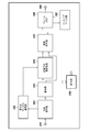
- FIG. 1 is a block diagram of an image encoding device according to an embodiment.
- FIG. 2 is a block diagram of an image decoding apparatus according to the embodiment.
- 9 is a flowchart illustrating an encoding process in the image encoding device according to the embodiment.
- 9 is a flowchart illustrating a decoding process in the image decoding device according to the embodiment.
- FIG. 2 is a hardware configuration diagram of a computer applicable to the image encoding device and the decoding device according to the embodiment.
- FIG. 1 is a block diagram of an image encoding device according to an embodiment.
- FIG. 2 is a block diagram of an image decoding apparatus according to the embodiment.
- 9 is a flowchart illustrating an encoding process in the image encoding device according to the embodiment.
- 9 is a flowchart illustrating a decoding process in the image decoding device according to the embodiment.
- FIG. 2 is a hardware configuration diagram of a computer applicable to the image encoding device and the decoding
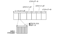
- FIG. 3 is a diagram illustrating an example of a bit stream structure generated by the image encoding device according to the embodiment.
- FIG. 3 is a diagram illustrating an example of a bit stream structure generated by the image encoding device according to the embodiment.
- FIG. 4 is a diagram illustrating an example of block division in the image encoding device according to the embodiment.
- FIG. 4 is a diagram illustrating an example of block division in the image encoding device according to the embodiment.
- FIG. 4 is a diagram illustrating an example of block division in the image encoding device according to the embodiment.
- FIG. 4 is a diagram illustrating an example of block division in the image encoding device according to the embodiment.
- FIG. 4 is a diagram illustrating an example of block division in the image encoding device according to the embodiment.
- FIG. 4 is a diagram illustrating an example of block division in the image encoding device according to the embodiment.
- FIG. 4 is a diagram illustrating an example of block division in the image encoding device according to the embodiment.
- FIG. 4 is a diagram illustrating an example of a quantization matrix used in the embodiment.
- FIG. 4 is a diagram illustrating an example of a quantization matrix used in the embodiment.
- FIG. 4 is a diagram illustrating an example of a quantization matrix used in the embodiment.
- FIG. 4 is a diagram illustrating an example of a quantization matrix used in the embodiment.
- FIG. 4 is a diagram illustrating an example of a quantization matrix used in the embodiment.
- FIG. 4 is a diagram illustrating an example of a quantization matrix used in the embodiment.
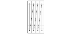
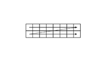
- FIG. 4 is a diagram illustrating a method for scanning elements of a quantization matrix according to the embodiment.
- FIG. 4 is a diagram illustrating an example of block division in the image encoding device according to the embodiment.
- FIG. 4 is a diagram illustrating an example of a quantization matrix used in the embodiment.
- FIG. 4 is a diagram illustrating a method for scanning elements of a quantization matrix according to the embodiment.
- FIG. 4 is a diagram illustrating a method for scanning elements of a quantization matrix according to the embodiment.
- FIG. 4 is a diagram illustrating a method for scanning elements of a quantization matrix according to the embodiment.
- FIG. 4 is a diagram illustrating a method for scanning elements of a quantization matrix according to the embodiment.
- FIG. 4 is a diagram illustrating a method for scanning elements of a quantization matrix according to the embodiment.
- FIG. 4 is a diagram illustrating a method for scanning elements of a quantization matrix according to the embodiment.
- FIG. 4 is a diagram illustrating a method for scanning elements of a quantization matrix according to the embodiment.
- FIG. 4 is a diagram illustrating a method for scanning elements of a quantization matrix according to the embodiment.
- FIG. 5 is a diagram illustrating an example of a difference value matrix of a quantization matrix generated in the embodiment.
- FIG. 5 is a diagram illustrating an example of a difference value matrix of a quantization matrix generated in the embodiment.
- FIG. 5 is a diagram illustrating an example of a difference value matrix of a quantization matrix generated in the embodiment.
- FIG. 9 is a diagram illustrating an example of an encoding table used for encoding a difference value of a quantization matrix.
- FIG. 9 is a diagram illustrating an example of an encoding table used for encoding a difference value of a quantization matrix.
- FIG. 1 is a block diagram of the image encoding apparatus according to the present embodiment.
- the image encoding device includes a control unit 150 that controls the entire device.
- the control unit 150 has a CPU, a ROM for storing programs executed by the CPU, and a RAM used as a work area of the CPU.
- the image encoding apparatus includes an input terminal 101, a block division unit 102, a quantization matrix holding unit 103, a prediction unit 104, a transformation / quantization unit 105, an inverse quantization / inverse transformation unit 106, an image reproduction unit 107, a frame It includes a memory 108, an in-loop filter unit 109, an encoding unit 110, an integrated encoding unit 111, an output terminal 112, and a quantization matrix encoding unit 113.
- the input terminal 101 inputs the image data to be encoded generated by the image data generation source on a frame basis.
- the type of the image data generation source is not limited, such as an imaging device, a file server or a storage medium storing image data to be encoded.
- the output terminal 112 outputs the encoded data to the output destination device.
- the output destination device is not particularly limited, such as a storage medium or a file server.
- the block dividing unit 102 divides the encoding target image data input from the input terminal 101 into a plurality of basic blocks, and sequentially outputs one of the basic blocks to the prediction unit 104 in the subsequent stage as a basic block of interest.
- the quantization matrix holding unit 103 is a rectangular block (including a positive direction and a rectangle), generates a plurality of types of quantization matrices, and holds them in an internal memory. Although there is no particular limitation on the method of generating the quantization matrix, the user may input the quantization matrix, calculate from the characteristics of the input image, or use a preset value as the initial value. .
- the quantization matrix holding unit 103 according to the present embodiment generates and holds a two-dimensional quantization matrix corresponding to the orthogonal transformation of 8 ⁇ 8 pixels, 4 ⁇ 8 pixels, and 8 ⁇ 4 pixels shown in FIGS. 8A to 8C. It is assumed that
- the quantization matrix refers to a matrix having components for weighting the transform coefficients after the orthogonal transform according to the frequency components. Note that the quantization matrix may be called a scaling list.
- the prediction unit 104 determines the type of block division with respect to the image data in the basic block unit, and refers to the frame memory 108 in the sub-block unit to refer to the frame memory 108 for intra prediction as intra-frame prediction and inter prediction as inter-frame prediction. And the like to generate predicted image data. Further, a prediction error is calculated from the input image data and the predicted image data and output.
- the prediction unit 104 also outputs information necessary for prediction, such as sub-block division, a prediction mode, and information (motion vector) for specifying the location of prediction data, along with prediction errors.
- information necessary for this prediction is referred to as prediction information.
- Transform / quantization section 105 performs orthogonal transformation (frequency transformation) on the prediction error input from prediction section 104 in subblock units to obtain a transformation coefficient. Then, the transform / quantization unit 105 quantizes the obtained transform coefficient using the quantization matrix stored in the quantization matrix holding unit 103, and obtains a quantized coefficient.
- the inverse quantization / inverse transform unit 106 inversely quantizes the quantized coefficient output from the transform / quantization unit 105 using the quantization matrix stored in the quantization matrix holding unit 103, and transforms the transform coefficient.
- the prediction error is reproduced, and the prediction error is reproduced by the inverse orthogonal transform.
- the image reproduction unit 107 generates predicted image data by appropriately referring to the frame memory 108 based on the prediction information output from the prediction unit 104. Then, the image reproducing unit 107 generates reproduced image data by adding the prediction error from the inverse quantization / inverse transforming unit 106 to the predicted image data, and stores the reproduced image data in the frame memory 108.
- the in-loop filter unit 109 performs an in-loop filter process such as a deblocking filter or a sample adaptive offset on the reproduced image reproduced by the image reproducing unit 107, and stores the filtered image in the frame memory 108 again.
- an in-loop filter process such as a deblocking filter or a sample adaptive offset on the reproduced image reproduced by the image reproducing unit 107
- Encoding section 110 encodes the quantized coefficient output from transform / quantization section 105 and the prediction information output from prediction section 104 to generate encoded data, and encodes the encoded data into integrated encoding section 111. Output to
- the quantization matrix encoding unit 113 encodes the quantization matrix output from the quantization matrix holding unit 103, generates quantization matrix encoded data, and outputs the encoded data to the integrated encoding unit 111. .
- the integrated encoding unit 111 generates header encoded data for storing encoded data of the quantization matrix output from the quantization matrix encoding unit 113 and the like. Further, integrated coding section 111 forms a bit stream by combining the header code data and the code data output from coding section 110, and outputs the coded data via output terminal 112.
- moving image data is input in units of frames.
- still image data for one frame may be used.
- the process of intra prediction encoding will be described.
- the present invention is not limited to this and can be applied to the process of inter prediction encoding.
- the block division unit 101 is described as dividing one frame of image data to be encoded into a plurality of basic blocks of 8 ⁇ 8 pixels, but is not limited thereto.
- the quantization matrix is encoded.
- the quantization matrix holding unit 103 holds a quantization matrix generated in advance. Specifically, the quantization matrix is determined according to the size of the sub-block to be encoded. The method of determining each element constituting the quantization matrix is not particularly limited. For example, a predetermined initial value may be used or may be set individually. In addition, it may be generated according to the characteristics of the image.
- the quantization matrix holding unit 103 holds the quantization matrices shown in FIGS. 8A to 8C.
- 8A shows a quantization matrix 800 corresponding to an orthogonal transform having an 8 ⁇ 8 pixel size
- FIG. 8B shows a quantization matrix 801 corresponding to an orthogonal transform having a 4 ⁇ 8 pixel size
- FIG. 8C shows an orthogonal matrix having an 8 ⁇ 4 pixel size.
- a quantization matrix 802 corresponding to the transformation is shown.
- the configuration is 64 ⁇ 8 ⁇ 8 pixels or 32 ⁇ 8 ⁇ 4 or 4 ⁇ 8 pixels, and each square in a thick frame represents each element constituting the quantization matrix.
- each element in the quantization matrix is not limited to this.
- another quantization matrix 803 corresponding to the 4 ⁇ 4 pixel size orthogonal transform as shown in FIG. become.
- a plurality of quantization matrices are held for orthogonal transforms of the same size. It is also possible.
- the quantization matrix realizes quantization processing according to human visual characteristics
- the element of the high frequency part corresponding to the lower part has a large value.
- the quantization matrix encoding unit 113 sequentially reads out the quantization matrices stored in the two-dimensional shape from the quantization matrix holding unit 106, scans each element, calculates a difference, and arranges them in a one-dimensional matrix. After that, it is encoded.
- each of the quantization matrices shown in FIGS. 8A to 8C uses the scanning method shown in FIGS. 9A, 9B, and 9D, and acquires the difference from the immediately preceding element for each element in the scanning order. Assume that the difference is coded.
- the quantization matrix encoding unit 113 calculates a difference from a preset initial value. Then, the difference between the subsequent element and the immediately preceding element is obtained. That is, since the second element is “9” located immediately below the first element, “+3” which is the difference from the immediately preceding element (first element) is obtained.
- the quantization matrix encoding unit 113 obtains this difference operation by scanning in the scanning order shown in FIG. 9A. For elements at the ends of the matrix, the difference between the element in the first row and the second column and the element in the third row and the first column, the difference between the element in the third row and the third column and the fourth row and the first column, etc. In other words, the difference is obtained. It is to be noted that the difference between the respective elements is also obtained by similarly performing the oblique scan as shown in FIG. 9F for the square (square) quantization matrix 803 of 4 ⁇ 4 pixels shown in FIG. 8D. Become.
- the quantization matrix encoding unit 113 performs a process of scanning vertically (from top to bottom) as shown in FIG. (Low frequency) to the right (high frequency). Specifically, since the first element “6” located at the upper left is the beginning of scanning, the quantization matrix encoding unit 113 acquires a difference from a preset initial value. Then, next, the quantization matrix encoding unit 113 reads the element “9” located immediately below, and acquires “+3” which is a difference from the immediately preceding element (first element).
- the quantization matrix encoding unit 113 acquires a difference “ ⁇ 24” between the element “13” in the first row and second column and the element “37” in the eighth row and first column.
- the quantization matrix encoding unit 113 obtains this difference operation by scanning in the scanning order shown in FIG. 9B.
- the quantization matrix encoding unit 113 performs horizontal (left to right) scanning as shown in FIG. 9D. It moves from the upper side (low frequency) to the lower side (high frequency). Specifically, since the first element “6” located at the upper left is the beginning of scanning, the quantization matrix encoding unit 113 acquires a difference from a preset initial value. Then, next, the quantization matrix encoding unit 113 acquires “+3” which is a difference between the element “9” located on the right of the element and the immediately preceding element (the first element “6”). I do.
- the quantization matrix encoding unit 113 acquires a difference “ ⁇ 24” between the element “13” in the second row and the first column and the element “37” in the first row and the eighth column.
- the quantization matrix encoding unit 113 obtains this difference operation by scanning in the scanning order shown in FIG. 9D.
- the quantization matrix encoding unit 113 sets the initial value to be referred to when calculating the difference of the first element of one quantization matrix to “8”. Value is good. In short, it suffices if the values are common to the encoding side and the decoding side. In particular, when the initial value is “0”, the first element becomes the calculation result as it is.
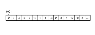
- the quantization matrices 800 to 802 in FIGS. 8A to 8C use the scanning methods of FIGS. 9A, 9B, and 9D, respectively, and use the one-dimensional rows 1000 to 1000 of the differences shown in FIGS. 10A to 10C. 1002 is generated.
- the quantization matrix encoding unit 113 further encodes the difference matrix to generate quantization matrix code data.
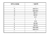
- encoding is performed using the encoding table shown in FIG. 11A.
- the encoding table is not limited to this.
- the encoding table shown in FIG. 11B may be used.
- the quantization matrix code data generated in this way is output to the integrated coding unit 111 at the subsequent stage.
- the quantization matrix used in the image encoding process generally has an element value that increases from a low-frequency portion located at the upper left to a high-frequency portion located at the lower right. Tend to move.
- the degree of element increase differs from each other due to the difference in the number of elements in the vertical and horizontal directions. Therefore, in the case of the quantization matrix 801 that is longer in the vertical direction than in the horizontal direction as shown in FIG. 8B, the degree of increase between the elements in the vertical direction is gentle, and the elements are scanned using the vertical scan as shown in FIG. 9B.
- the difference value between the elements becomes smaller, and as a result, the code amount can be reduced.
- the quantization matrix 802 that is longer in the horizontal direction than in the vertical direction as shown in FIG. 8C, since the degree of increase between elements in the horizontal direction is gentle, the elements are scanned using a horizontal scan as shown in FIG. 9D. By doing so, the code amount can be reduced as a result.
- the quantization matrix has been described as having a size of 8 ⁇ 8, 4 ⁇ 8, and 8 ⁇ 4 pixels.
- N the relationship between the integers N and M
- N ⁇ N pixels M ⁇ It can be generalized to the size of N pixels and N ⁇ M pixels. Further, other sizes may be included.
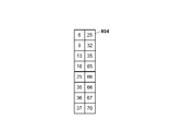
- the quantization matrix holding unit 103 holds the quantization matrix 804 in FIG. 8E.
- the quantization matrix encoding unit 113 acquires and encodes the difference between the elements of the quantization matrix using the vertical scan illustrated in FIG. 9G.
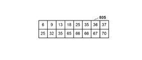
- the quantization matrix holding unit 103 holds the quantization matrix 805 in FIG. 8F.
- the quantization matrix encoding unit 113 acquires and encodes the differences between the elements of the quantization matrix using the horizontal scan shown in FIG. 9H.
- the integrated encoding unit 111 encodes header information necessary for encoding the image data, and integrates the encoded data of the quantization matrix. At this time, the integrated encoding unit 111 also outputs information indicating the correspondence between the type of the quantization matrix size (for example, 8 ⁇ 8, 4 ⁇ 8, and 8 ⁇ 4) and each piece of quantization matrix encoded data in the header information. Include in. Briefly, if the size type of the quantization matrix is 8 ⁇ 8, 4 ⁇ 8, or 8 ⁇ 4, the quantization matrix encoded data may be stored in the same order. However, the order is not limited to this, and quantization matrix encoded data may be stored in ascending order of 4 ⁇ 8, 8 ⁇ 4, 8 ⁇ 8.
- the block division unit 102 divides the input image data into a plurality of basic blocks, and outputs an image for each basic block to the prediction unit 104. In the present embodiment, it is assumed that an image of a basic block unit of 8 ⁇ 8 pixels is output.
- the prediction unit 104 performs a prediction process on the image data in basic block units input from the block division unit 102. Specifically, the type of block division for dividing the basic block into smaller sub-blocks is determined, and intra prediction modes such as horizontal prediction and vertical prediction are determined for each sub-block.
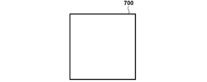
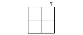
- FIGS. 7A to 7F show examples of types of block division obtained by dividing a basic block.
- the bold frames 700 to 705 represent basic blocks, each of which has a configuration of 8 ⁇ 8 pixels for simplicity of description, and each square in the bold frame represents a sub-block.
- FIG. 7B shows an example of a conventional square sub-block, in which the basic block 701 is divided into four sub-blocks of 4 ⁇ 4 pixel size.
- 7C to 7F show an example of a rectangular sub-block.
- FIG. 7C shows an example in which the basic block 702 is divided into two sub-blocks of 4 ⁇ 8 pixel size.
- FIG. 7A shows an example in which the basic block 702 is divided into two sub-blocks of 4 ⁇ 8 pixel size.
- FIG. 7D shows an example in which the basic block 702 is divided into two sub-blocks of 8 ⁇ 4 pixel size.
- FIGS. 7E and 7F show examples in which the basic blocks 704 and 705 are divided into three rectangular sub-blocks at a size ratio of 1: 2: 1, although the division directions are different.
- the encoding process is performed using not only a square but also a rectangular sub-block.
- the basic block of 8 ⁇ 8 pixels is not divided into sub-blocks (FIG. 7A), divided along the horizontal direction (FIG. 7C), and divided along the vertical direction (FIG. 7D). Is determined, but the sub-block division method is not limited to this.
- a quadtree division as shown in FIG. 7B or a ternary tree division as shown in FIGS. 7E and 7F may be used.
- the prediction unit 104 generates predicted image data of a sub-block from the determined intra prediction mode and the coded pixels, generates a prediction error from the input image data and the predicted image data, and generates a transform / quantization unit 105. Output to Further, the prediction unit 104 outputs information such as the sub-block division and the intra prediction mode to the encoding unit 110 and the image reproduction unit 107 as prediction information.
- the transform / quantization unit 105 performs orthogonal transformation and further quantization on the input residual indicating the prediction error, and generates a residual coefficient indicating the residual.
- the transform / quantization unit 105 performs an orthogonal transform process corresponding to the size of the sub-block, and generates an orthogonal transform coefficient.
- the transform / quantization unit 105 quantizes the orthogonal transform coefficients using the quantization matrix stored in the quantization matrix holding unit 103, and generates a residual coefficient.
- the quantization matrix 800 in FIG. 8A is used for the sub-block 700 corresponding to FIG. 7A.
- the quantization matrix 801 shown in FIG. 8B is used for the sub-block 702 in FIG.
- Transform / quantization section 105 outputs the generated residual coefficient to encoding section 110 and inverse quantization / inverse transform section 106.
- the inverse quantization / inverse transform unit 106 inversely quantizes the input residual coefficient using the quantization matrix stored in the quantization matrix holding unit 103 to reproduce the transform coefficient. Further, the inverse quantization / inverse transform unit 106 performs an inverse orthogonal transform on the reproduced transform coefficient to reproduce a prediction error. Note that the quantization matrix used by the inverse quantization / inverse transformation unit 106 at the time of the inverse quantization process is a quantization matrix corresponding to the sub-block division used by the transformation / quantization unit 105. The inverse quantization / inverse transform unit 106 outputs the reproduced prediction error to the image reproducing unit 107.
- the image reproducing unit 107 reproduces a predicted image by appropriately referring to the frame memory 108 based on the prediction information input from the prediction unit 104. Then, the image reproducing unit 107 reproduces image data from the reproduced predicted image and the reproduced prediction error input from the inverse quantization / inverse transform unit 106 and stores the image data in the frame memory 108.
- the in-loop filter unit 109 reads out the image reproduced by the image reproducing unit 107 from the frame memory 108, and performs an in-loop filter process such as a deblocking filter. Then, the in-loop filter unit 109 stores the filtered image in the frame memory 108 again.
- the coding unit 110 performs entropy coding of the residual coefficient generated by the transform / quantization unit 105 and the prediction information input from the prediction unit 104 in block units to generate coded data.
- the method of entropy coding is not particularly specified, but Golomb coding, arithmetic coding, Huffman coding, or the like can be used.
- encoding section 110 outputs the generated encoded data to integrated encoding section 111.
- the integrated encoding unit 111 multiplexes the encoded data and the like input from the encoding unit 110 together with the encoded data of the header to form a bit stream. Finally, the bit stream is output from the terminal 112 to the outside.
- FIG. 6A is an example of a bit stream output in the embodiment.
- the sequence header contains the code data of the quantization matrix, and is composed of the coding result of each element.
- the position to be coded is not limited to this, and it goes without saying that a configuration may be adopted in which the coded position is coded in a picture header section or other header sections.
- the quantization matrix can be updated by newly encoding the quantization matrix.
- all the quantization matrices may be rewritten, or a part of them may be changed by designating the transform block size of the quantization matrix to be rewritten.
- FIG. 3 is a flowchart showing an encoding process in the image encoding device according to the embodiment.
- the control unit 150 controls the quantization matrix holding unit 103 to generate and hold a quantization matrix.
- the quantization matrix holding unit 103 of this embodiment generates and holds the three types of quantization matrices 800 to 802 shown in FIGS. 8A to 8C.
- step S302 the control unit 150 controls the quantization matrix encoding unit 113 to scan the quantization matrix generated and held in step S301, calculate the difference between the elements, and generate a difference matrix.
- the difference matrices shown in FIGS. 10A to 10C are generated by using the scanning methods of FIGS. 9A, 9B, and 9D for the quantization matrices of FIGS. 8A to 8C, respectively.
- the control unit 150 controls the quantization matrix coding unit 113 to cause the generated difference matrix to be coded and generate quantization matrix coded data.
- step S303 the control unit 150 controls the integrated encoding unit 111 to encode and output the generated quantization matrix code data and header information necessary for encoding the image data.
- control unit 150 controls block division unit 102 to divide the input image in frame units into basic block units.
- control unit 150 controls prediction unit 104, and executes prediction processing on the image data in basic block units generated in S304. Then, the prediction unit 104 generates information on the type of block division obtained by dividing the basic block as shown in FIGS. 7A to 7F, prediction information such as an intra prediction mode, and predicted image data. Note that, as information on the type of block division, the identifier of the type of block division shown in FIGS. 7A to 7F is encoded.
- an identifier relating to the type of the shape of the sub-block itself (for example, 4 ⁇ 8 pixel size, 8 ⁇ 2 pixel size, etc.) may be encoded. Further, the prediction unit 104 calculates a prediction error from the input image data and the predicted image data.
- control unit 150 controls transform / quantization unit 105 to perform orthogonal transform on the prediction error calculated in S305, and generate a transform coefficient. Further, the control unit 150 controls the transform / quantization unit 105 to cause the quantization using the quantization matrix generated and held in S301 to generate a residual coefficient.
- the quantization matrix of FIG. 8A is used for the block division corresponding to FIG. 7A.
- the quantization matrix of FIG. 8B is used for the block division of FIG. 7C
- the quantization matrix of FIG. 8C is used for the block division of FIG. 7D.
- control unit 150 controls inverse quantization / inverse transforming unit 106 to perform inverse quantization on the residual coefficient generated in S305 using the quantization matrix generated and held in S301. And regenerate the transform coefficients.
- the inverse quantization / inverse transform unit 106 performs inverse orthogonal transform on the transform coefficient and reproduces a prediction error.
- control unit 150 controls image reproduction unit 107 to reproduce a predicted image based on the prediction information generated in S305. Further, the control unit 150 causes the image reproducing unit 107 to reproduce image data from the reproduced predicted image and the prediction error generated in S307.
- control unit 159 controls encoding unit 110 to encode the prediction information generated in S305 and the residual coefficient generated in S306, and generate code data.
- the encoding unit 110 encodes an identifier related to the type of block division shown in FIGS. 7A to 7F.
- the control unit 150 controls the integrated encoding unit 111 to generate a bit stream including other encoded data.
- control unit 150 determines whether or not encoding of all basic blocks in the frame has been completed. If it is determined that the processing has been completed, the control unit 150 proceeds to step S311. Otherwise, the control unit 150 returns the processing to step S304 in order to perform target encoding on the next basic block.
- step S311 the control unit 150 controls the in-loop filter unit 109, performs in-loop filter processing on the image data reproduced in step S308, generates a filtered image, and ends the processing.
- the quantization matrix and the method of scanning the elements to be used are uniquely determined according to the type of the size of the sub-block.
- an identifier may be encoded in the header. For example, information indicating whether to use the scanning method shown in FIG. 9B or the scanning method shown in FIG. 9D is encoded in a header portion as a quantization matrix scanning method information code, and the bit stream shown in FIG. It is good also as composition which generates. Thereby, each quantization matrix is scanned in an optimal manner, and a bit stream with a smaller code amount of the quantization matrix can be generated.
- the vertically long quantization matrix 801 in FIG. 8B is scanned by the vertical scan in FIG. 9B
- the horizontally long quantization matrix 802 in FIG. 8C is scanned by the horizontal scan in FIG. 9C.
- the scanning method used is not limited to this.
- a scanning method as shown in FIG. 9D may be used for the quantization matrix 801 in FIG. 8B, and the elements in the horizontal direction are scanned and encoded before the elements in the horizontal direction. Can be realized.
- a scanning method as shown in FIG. 9E may be used for the quantization matrix 802 in FIG. 8C.
- FIG. 2 is a block diagram illustrating a configuration of the image decoding device according to the present embodiment. This image decoding device decodes encoded data generated by the image encoding device of the above-described embodiment.
- the image decoding device includes a control unit 250 that controls the entire device.
- the control unit 250 has a CPU, a ROM for storing programs executed by the CPU, and a RAM used as a work area of the CPU.
- the image decoding apparatus includes an input terminal 201, a separation decoding unit 202, a decoding unit 203, an inverse quantization / inverse conversion unit 204, an image reproduction unit 205, a frame memory 206, an in-loop filter unit 207, an output terminal 208, It has a quantization matrix decoding unit 209.
- the input terminal 201 is for inputting an encoded bit stream
- the input source is, for example, a storage medium storing the encoded stream, but may be input from a network, and the type thereof is not limited.
- the separation / decoding unit 202 separates the input bit stream into information on decoding processing and code data on coefficients. Further, the separation / decoding unit 202 decodes the encoded data existing in the header of the bit stream. The separation / decoding unit 202 of the present embodiment separates the quantization matrix coded data and outputs it to the subsequent stage. The separation / decoding unit 202 also performs the reverse operation of the integrated coding unit 111 in FIG.
- the quantization matrix decoding unit 209 decodes the quantization matrix code and reproduces the quantization matrix.
- the decoding unit 203 decodes the encoded data of the image output from the separation decoding unit 202, and reproduces the residual coefficient and the prediction information.
- the inverse quantization / inverse transform unit 204 performs inverse quantization on the residual coefficient using the reproduced quantization matrix to obtain a transform coefficient, similarly to the inverse quantization / inverse transform unit 106 in FIG. Perform orthogonal transformation to recover the prediction error.
- the image reproducing unit 205 generates predicted image data by appropriately referring to the frame memory 206 based on the input prediction information. Then, reproduced image data is generated from the predicted image data and the prediction error reproduced by the inverse quantization / inverse transform unit 204, and is stored in the frame memory 206 again.
- the in-loop filter unit 207 performs an in-loop filter process such as a deblocking filter on the reproduced image stored in the frame memory 206 in the same manner as the in-loop filter unit 109 in FIG. 207 is stored again.
- the output terminal sequentially outputs the frame images stored in the frame memory 206 to the outside.
- the output destination is the display device, but may be another device.
- the image decoding device is configured to input the bit stream generated by the image encoding device according to the embodiment on a frame basis, but may be configured to input a still image bit stream for one frame. Absent. Further, in the present embodiment, only the intra prediction decoding process will be described for ease of description, but the present invention is not limited to this and can be applied to the inter prediction decoding process.
- the separation / decoding unit 202 separates a bit stream for one frame input via the input terminal 201 into coded data related to decoding processing information and coefficients, and decodes coded data existing in a header part of the bit stream. . More specifically, the separation / decoding unit 202 reproduces the encoded data of the quantization matrix. The separation / decoding section 202 extracts the encoded data of the quantization matrix from the sequence header of the bit stream shown in FIG. 6A and outputs it to the quantization matrix decoding section 209. Subsequently, the separation / decoding unit 202 reproduces the code data of the picture data in basic block units and outputs the code data to the decoding unit 203.
- the quantization matrix decoding unit 209 first decodes the input quantization matrix code data and reproduces a one-dimensional difference matrix.
- decoding is performed using the encoding table shown in FIG. 11A.
- the encoding table is not limited to this, and other encoding tables may be used as long as the same encoding table as in the present embodiment is used. May be.
- the quantization matrix decoding unit 209 performs reverse scanning on the reproduced one-dimensional difference matrix to reproduce a two-dimensional quantization matrix.
- scanning similar to that performed by the quantization matrix encoding unit 113 of the present embodiment is performed. That is, the quantization matrix decoding unit 209 of this embodiment uses the scanning methods shown in FIGS. 9A, 9B, and 9D to calculate the difference matrices 1000 to 1002 shown in FIGS. 10A to 10C, respectively.
- These three types of quantization matrices are reproduced and stored in an internal memory (not shown) of the reproduction matrix.
- the decoding unit 203 decodes the encoded data of the image and reproduces the quantization coefficient and the prediction information of the block of interest.
- the decoding unit 203 outputs the reproduced quantization coefficient to the inverse quantization / inverse transformation unit 204, and outputs the reproduced prediction information to the image reproduction unit 205.
- the inverse quantization / inverse transform unit 204 performs inverse quantization on the input quantized coefficient using the quantization matrix reproduced by the quantization matrix decoding unit 209 to generate an orthogonal transform coefficient. Further, the inverse quantization / inverse transform unit 204 performs an inverse orthogonal transform to reproduce a prediction error. Then, the inverse quantization / inverse transforming unit 204 outputs the reproduced prediction information to the image reproducing unit 205.
- a quantization matrix to be used is determined according to the type of the size of the sub-block to be decoded. In the present embodiment, the quantization matrix in FIG. 8A is used for the block division corresponding to FIG. 7A. I do. Similarly, the quantization matrix of FIG. 8B is used for the block division of FIG. 7C, and the quantization matrix of FIG. 8C is used for the block division of FIG. 7D.
- the image reproducing unit 205 refers to the frame memory 206 based on the prediction information input from the decoding unit 203 and reproduces a predicted image.
- the image reproducing unit 205 reproduces image data by adding the prediction error input from the inverse quantization / inverse transforming unit 204 to the predicted image, and stores the reproduced image data in the frame memory 206. I do.
- the stored image data is referred to at the time of prediction at the time of decoding the subsequent encoded data.
- the in-loop filter unit 207 reads a reproduced image from the frame memory 206 and performs in-loop filter processing such as a deblocking filter, similarly to the in-loop filter unit 109 in FIG. Then, the in-loop filter unit 207 stores the filtered image in the frame memory 206 again. The reproduced image stored in the frame memory 206 is finally output from the output terminal 208 to the outside.
- in-loop filter processing such as a deblocking filter
- FIG. 4 is a flowchart illustrating a decoding process of the control unit 250 in the image decoding device according to the embodiment.
- control unit 250 controls the demultiplexing / decoding unit 202 to separate the bit stream from the bit stream into the information on the decoding process and the encoded data on the coefficients, and decode the encoded data in the header part.
- the separation / decoding section 202 reproduces the quantization matrix code data.
- the control unit 250 controls the quantization matrix decoding unit 209 to decode the quantization matrix code data reproduced at S401. As a result, a one-dimensional difference matrix as shown in FIGS. 10A to 10C is reproduced. Further, the control unit 250 controls the quantization matrix decoding unit 209, scans the reproduced one-dimensional difference matrix, and reproduces a two-dimensional quantization matrix. That is, the quantization matrix decoding unit 209 converts the difference matrices shown in FIGS. 10A to 10C into the three types of quantization shown in FIGS. 8A to 8C by using the scanning methods shown in FIGS. 9A, 9B, and 9D, respectively. Regenerate the matrix and store it in internal memory.
- step S403 the control unit 250 controls the decoding unit 203 to decode the encoded data of the image separated in step S401, and reproduce the quantization coefficient and the prediction information.
- the decoding unit 203 decodes the division information from the bit stream and obtains information on the type of block division as shown in FIGS. 7A to 7F.
- the identifiers of the types of block division shown in FIGS. 7A to 7F are acquired. It is assumed that the type of block division corresponding to these identifiers is known in the image decoding device. That is, since the control unit 250 can determine the type of block division corresponding to the acquired identifier, it can determine which type of quantization matrix to use. For example, when an identifier related to the type of block division corresponding to FIG. 7C is obtained, the quantization matrix of the sub-block of 4 ⁇ 8 pixels is used twice.
- identifiers relating to the type of the shape of the sub-block itself for example, 4 ⁇ 8 pixel size, 8 ⁇ 2 pixel size, etc.
- these identifiers are decoded from the bit stream as information on the type of block division, these identifiers and It is assumed that the type of the corresponding sub-block shape is known.
- the decoding unit 203 determines a quantization matrix to be used in accordance with the obtained type of block division. For example, when the block division is as shown in FIG. 7C, the quantization matrix of 4 ⁇ 8 pixels shown in FIG. 8B is used twice. When the block division is as shown in FIG. 7E, the 2 ⁇ 8 pixel size quantization matrix of FIG. 8E, the 4 ⁇ 8 pixel size quantization matrix of FIG. 8B, and again the 2 ⁇ 8 pixel size quantization matrix of FIG. 8E are obtained. used.
- control unit 250 controls the inverse quantization / inverse transformation unit 204 to cause the quantized coefficients to undergo inverse quantization using the quantization matrix reproduced in S402, and , And then perform an inverse orthogonal transform to reproduce the prediction error.
- control unit 250 controls the image reproduction unit 205 to reproduce the prediction information and the prediction image generated in S403. Further, the control unit 250 controls the image reproducing unit 205 to reproduce the image data from the reproduced predicted image and the prediction error generated in S404.
- control unit 250 determines whether or not decoding of all basic blocks in the frame has been completed. If the decoding of all the basic blocks has not been completed, the control unit 250 returns the processing to 403, and performs the decoding processing of the next recording block. If decoding of all basic blocks in the frame has been completed, the control unit 250 advances the process to S407. In step S407, the control unit 250 controls the in-loop filter unit 207 to cause the image data reproduced in step S405 to perform in-loop filter processing, and stores the filtered image in the frame memory again. This processing ends.
- the quantization matrix and the method of scanning the elements to be used are uniquely determined according to the type of the size of the sub-block. May be decoded from the header. For example, a configuration in which information indicating whether to use the scanning method shown in FIG. 9B or the scanning method shown in FIG. 9D is decoded as a quantization matrix scanning method information code from the header portion of the bit stream shown in FIG. 6B. It is good. Thereby, each quantization matrix is scanned in an optimal manner, and a bit stream with a smaller code amount of the quantization matrix can be decoded.
- the vertical quantization matrix in FIG. 8B is decoded by reverse scanning in the vertical scan in FIG. 9B
- the horizontal quantization matrix in FIG. 8C is decoded in the horizontal scan in FIG. 9D.
- the scanning method is not limited to this.
- a scanning method as shown in FIG. 9C may be used for the vertically long quantization matrix in FIG. 8B.
- the code amount is similarly reduced.
- the reduced bit stream can be decoded.
- a scanning method as shown in FIG. 9E may be used for the horizontally long quantization matrix in FIG. 8C.
- FIGS. 1 and 2 Each of the processing units shown in FIGS. 1 and 2 has been described in the above embodiment as being configured by hardware. However, an example in which the processing performed by each processing unit illustrated in these drawings is realized by a computer program executed by an information processing device represented by a personal computer will be described as a second embodiment.
- FIG. 5 is a block diagram showing a configuration example of hardware of a computer according to the second embodiment.
- the CPU 501 controls the entire computer using computer programs and data stored in the RAM 502 and the ROM 503.
- the RAM 502 is used to temporarily store computer programs and data loaded from the external storage device 506, data obtained from the outside via an I / F (interface) 507, and the like. Further, the RAM 502 has a work area used when the CPU 501 executes various processes. That is, for example, the RAM 502 can be allocated as a frame memory, or can appropriately provide other various areas.
- the ROM 503 stores setting data (including BIOS) of the computer, a boot program, and the like.
- the operation unit 504 includes a keyboard, a mouse, and the like, and can input various instructions to the CPU 501 when operated by a user of the computer.
- the display unit 505 displays the processing result of the CPU 501. Further, the display unit 505 is configured by, for example, a liquid crystal display.
- the external storage device 506 is a large-capacity information storage device represented by a hard disk drive.
- the external storage device 506 stores an OS (Operating System) and a computer program for causing the CPU 501 to realize the functions of each unit illustrated in FIGS. 1 and 2. Further, the external storage device 506 may store image data to be processed.
- OS Operating System
- FIGS. 1 and 2 Further, the external storage device 506 may store image data to be processed.
- the computer programs and data stored in the external storage device 506 are loaded into the RAM 502 as appropriate under the control of the CPU 501, and are processed by the CPU 501.
- the I / F 507 can be connected to a network such as a LAN and the Internet, and other devices such as a projection device and a display device.
- the computer acquires and sends various information via the I / F 507. Or you can.
- a bus 508 connects the above-described units.
- the CPU 501 executes the boot program in the ROM 503 to load the OS from the external storage device 506 into the RAM 502 and execute the OS.
- the user interface of the operation unit 504 and the display unit 505 functions.
- the CPU 501 reads the program from the external storage device 506 to the RAM 502 and executes the program under the OS.
- the CPU 501 performs processing as each processing unit in FIG. 1 or FIG. 2, and the CPU 501 performs control according to FIG. 3 or FIG. 4 so that the present device functions as an image encoding device or an image decoding device.
- the frame memory in FIGS. 1 and 2 is replaced by the RAM 502. It is assumed that the image data to be encoded and the encoded image data are stored in the external storage device 506.
- the present invention supplies a program for realizing one or more functions of the above-described embodiments to a system or an apparatus via a network or a storage medium, and one or more processors in a computer of the system or the apparatus read and execute the program. It can also be realized by the following processing. Further, it can be realized by a circuit (for example, an ASIC) that realizes one or more functions.
- a circuit for example, an ASIC
- the present invention is used for an encoding device and a decoding device that encode and decode still images and moving images.
- the present invention is applicable to an encoding method and a decoding method using a quantization matrix.
Landscapes
- Engineering & Computer Science (AREA)
- Multimedia (AREA)
- Signal Processing (AREA)
- Compression Or Coding Systems Of Tv Signals (AREA)
Abstract
La présente invention permet d'effectuer un codage efficace à l'aide de multiples types de matrices de quantification rectangulaires et de supprimer les quantités de code des matrices de quantification elles-mêmes. À cet effet, un dispositif de codage d'image pour coder une image comprend : une unité de division qui divise une image à coder en n'importe lequel de multiples types prédéfinis de blocs rectangulaires; une unité de génération qui génère de multiples types de matrices de quantification correspondant respectivement aux multiples types de blocs rectangulaires; une première unité de codage qui code chacune des matrices de quantification générées par l'unité de génération dans un ordre de balayage correspondant à sa forme; une unité de quantification qui convertit en fréquence une image d'un bloc rectangulaire remarqué obtenu par l'unité de division, et quantifie un coefficient de conversion obtenu à l'aide d'une matrice de quantification correspondant à la forme du bloc rectangulaire notifié; une seconde unité de codage qui code le coefficient de conversion quantifié obtenu par l'unité de quantification; et une unité d'intégration qui intègre des données codées obtenues par la première unité de codage et des données codées obtenues par la seconde unité de codage.
Applications Claiming Priority (2)
| Application Number | Priority Date | Filing Date | Title |
|---|---|---|---|
| JP2018-125298 | 2018-06-29 | ||
| JP2018125298 | 2018-06-29 |
Publications (1)
| Publication Number | Publication Date |
|---|---|
| WO2020003740A1 true WO2020003740A1 (fr) | 2020-01-02 |
Family
ID=68985602
Family Applications (1)
| Application Number | Title | Priority Date | Filing Date |
|---|---|---|---|
| PCT/JP2019/018257 Ceased WO2020003740A1 (fr) | 2018-06-29 | 2019-05-07 | Dispositif de codage d'image, dispositif de décodage d'image, procédés de commande et programme correspondants |
Country Status (3)
| Country | Link |
|---|---|
| JP (1) | JP2020010320A (fr) |
| TW (1) | TW202002635A (fr) |
| WO (1) | WO2020003740A1 (fr) |
Cited By (1)
| Publication number | Priority date | Publication date | Assignee | Title |
|---|---|---|---|---|
| CN111556319A (zh) * | 2020-05-14 | 2020-08-18 | 电子科技大学 | 一种基于矩阵分解的视频编码方法 |
Citations (6)
| Publication number | Priority date | Publication date | Assignee | Title |
|---|---|---|---|---|
| WO2005072312A2 (fr) * | 2004-01-20 | 2005-08-11 | Matsushita Electric Industrial Co., Ltd. | Procede de codage d'image, procede de decodage d'image, appareil de codage d'image, appareil de decodage d'image, et programme correspondant |
| WO2012160890A1 (fr) * | 2011-05-20 | 2012-11-29 | ソニー株式会社 | Dispositif de traitement d'image et procédé de traitement d'image |
| WO2013005386A1 (fr) * | 2011-07-01 | 2013-01-10 | Panasonic Corporation | Procédé et appareil pour coder et décoder une vidéo à l'aide d'une matrice de quantification adaptative pour des unités de transformation carrées et rectangulaires |
| JP2013038758A (ja) * | 2011-07-13 | 2013-02-21 | Canon Inc | 画像符号化装置、画像符号化方法及びプログラム、画像復号装置、画像復号方法及びプログラム |
| WO2013065259A1 (fr) * | 2011-11-01 | 2013-05-10 | 日本電気株式会社 | Dispositif de codage vidéo, dispositif de décodage vidéo, procédé de codage vidéo, procédé de décodage vidéo et programme |
| WO2013157825A1 (fr) * | 2012-04-16 | 2013-10-24 | 한국전자통신연구원 | Procédé et dispositif de codage/décodage d'image |
-
2019
- 2019-05-07 WO PCT/JP2019/018257 patent/WO2020003740A1/fr not_active Ceased
- 2019-05-16 TW TW108116856A patent/TW202002635A/zh unknown
- 2019-05-31 JP JP2019103181A patent/JP2020010320A/ja active Pending
Patent Citations (6)
| Publication number | Priority date | Publication date | Assignee | Title |
|---|---|---|---|---|
| WO2005072312A2 (fr) * | 2004-01-20 | 2005-08-11 | Matsushita Electric Industrial Co., Ltd. | Procede de codage d'image, procede de decodage d'image, appareil de codage d'image, appareil de decodage d'image, et programme correspondant |
| WO2012160890A1 (fr) * | 2011-05-20 | 2012-11-29 | ソニー株式会社 | Dispositif de traitement d'image et procédé de traitement d'image |
| WO2013005386A1 (fr) * | 2011-07-01 | 2013-01-10 | Panasonic Corporation | Procédé et appareil pour coder et décoder une vidéo à l'aide d'une matrice de quantification adaptative pour des unités de transformation carrées et rectangulaires |
| JP2013038758A (ja) * | 2011-07-13 | 2013-02-21 | Canon Inc | 画像符号化装置、画像符号化方法及びプログラム、画像復号装置、画像復号方法及びプログラム |
| WO2013065259A1 (fr) * | 2011-11-01 | 2013-05-10 | 日本電気株式会社 | Dispositif de codage vidéo, dispositif de décodage vidéo, procédé de codage vidéo, procédé de décodage vidéo et programme |
| WO2013157825A1 (fr) * | 2012-04-16 | 2013-10-24 | 한국전자통신연구원 | Procédé et dispositif de codage/décodage d'image |
Cited By (1)
| Publication number | Priority date | Publication date | Assignee | Title |
|---|---|---|---|---|
| CN111556319A (zh) * | 2020-05-14 | 2020-08-18 | 电子科技大学 | 一种基于矩阵分解的视频编码方法 |
Also Published As
| Publication number | Publication date |
|---|---|
| JP2020010320A (ja) | 2020-01-16 |
| TW202002635A (zh) | 2020-01-01 |
Similar Documents
| Publication | Publication Date | Title |
|---|---|---|
| JP7610690B2 (ja) | 画像復号装置及び方法及びプログラム | |
| JP2023105156A (ja) | 画像符号化装置、画像符号化方法、及びプログラム | |
| JP7685102B2 (ja) | 画像符号化装置及び画像復号装置及びそれらの制御方法及びプログラム | |
| JP2023113858A (ja) | 画像復号装置、画像復号方法、及びプログラム | |
| WO2020184223A1 (fr) | Décodeur d'image, procédé de décodage d'image, et programme | |
| JP2024023793A (ja) | 画像符号化装置及び画像復号装置及び画像符号化方法及び画像復号方法及びプログラム | |
| WO2021054012A1 (fr) | Dispositif de codage d'image, dispositif de décodage d'image, procédé de commande associé, et programme | |
| WO2020003740A1 (fr) | Dispositif de codage d'image, dispositif de décodage d'image, procédés de commande et programme correspondants | |
| WO2020183859A1 (fr) | Dispositif de codage d'image, dispositif de décodage d'image, procédé de codage d'image, procédé de décodage d'image, et programme | |
| HK40103266A (zh) | 图像编码设备、图像解码设备和控制方法 | |
| HK40104024A (zh) | 图像编码设备、图像解码设备和控制方法 | |
| HK40103532A (zh) | 图像编码设备、图像解码设备和控制方法 | |
| HK40103530A (zh) | 图像编码设备、图像解码设备和控制方法 | |
| HK40103529A (zh) | 图像编码设备、图像解码设备和控制方法 | |
| JP2021150723A (ja) | 画像符号化装置、画像符号化方法、及びプログラム、画像復号装置、画像復号方法、及びプログラム |
Legal Events
| Date | Code | Title | Description |
|---|---|---|---|
| 121 | Ep: the epo has been informed by wipo that ep was designated in this application |
Ref document number: 19825656 Country of ref document: EP Kind code of ref document: A1 |
|
| NENP | Non-entry into the national phase |
Ref country code: DE |
|
| 122 | Ep: pct application non-entry in european phase |
Ref document number: 19825656 Country of ref document: EP Kind code of ref document: A1 |