WO2020003766A1 - 巻線装置及びそれを用いた巻線方法 - Google Patents
巻線装置及びそれを用いた巻線方法 Download PDFInfo
- Publication number
- WO2020003766A1 WO2020003766A1 PCT/JP2019/018807 JP2019018807W WO2020003766A1 WO 2020003766 A1 WO2020003766 A1 WO 2020003766A1 JP 2019018807 W JP2019018807 W JP 2019018807W WO 2020003766 A1 WO2020003766 A1 WO 2020003766A1
- Authority
- WO
- WIPO (PCT)
- Prior art keywords
- wire
- core
- winding
- pair
- flyers
- Prior art date
- Legal status (The legal status is an assumption and is not a legal conclusion. Google has not performed a legal analysis and makes no representation as to the accuracy of the status listed.)
- Ceased
Links
Images






Classifications
-
- H—ELECTRICITY
- H01—ELECTRIC ELEMENTS
- H01F—MAGNETS; INDUCTANCES; TRANSFORMERS; SELECTION OF MATERIALS FOR THEIR MAGNETIC PROPERTIES
- H01F41/00—Apparatus or processes specially adapted for manufacturing or assembling magnets, inductances or transformers; Apparatus or processes specially adapted for manufacturing materials characterised by their magnetic properties
- H01F41/02—Apparatus or processes specially adapted for manufacturing or assembling magnets, inductances or transformers; Apparatus or processes specially adapted for manufacturing materials characterised by their magnetic properties for manufacturing cores, coils, or magnets
- H01F41/04—Apparatus or processes specially adapted for manufacturing or assembling magnets, inductances or transformers; Apparatus or processes specially adapted for manufacturing materials characterised by their magnetic properties for manufacturing cores, coils, or magnets for manufacturing coils
- H01F41/06—Coil winding
- H01F41/082—Devices for guiding or positioning the winding material on the former
- H01F41/088—Devices for guiding or positioning the winding material on the former using revolving flyers
-
- H—ELECTRICITY
- H01—ELECTRIC ELEMENTS
- H01F—MAGNETS; INDUCTANCES; TRANSFORMERS; SELECTION OF MATERIALS FOR THEIR MAGNETIC PROPERTIES
- H01F41/00—Apparatus or processes specially adapted for manufacturing or assembling magnets, inductances or transformers; Apparatus or processes specially adapted for manufacturing materials characterised by their magnetic properties
- H01F41/02—Apparatus or processes specially adapted for manufacturing or assembling magnets, inductances or transformers; Apparatus or processes specially adapted for manufacturing materials characterised by their magnetic properties for manufacturing cores, coils, or magnets
- H01F41/04—Apparatus or processes specially adapted for manufacturing or assembling magnets, inductances or transformers; Apparatus or processes specially adapted for manufacturing materials characterised by their magnetic properties for manufacturing cores, coils, or magnets for manufacturing coils
- H01F41/06—Coil winding
- H01F41/094—Tensioning or braking devices
-
- H—ELECTRICITY
- H01—ELECTRIC ELEMENTS
- H01F—MAGNETS; INDUCTANCES; TRANSFORMERS; SELECTION OF MATERIALS FOR THEIR MAGNETIC PROPERTIES
- H01F41/00—Apparatus or processes specially adapted for manufacturing or assembling magnets, inductances or transformers; Apparatus or processes specially adapted for manufacturing materials characterised by their magnetic properties
- H01F41/02—Apparatus or processes specially adapted for manufacturing or assembling magnets, inductances or transformers; Apparatus or processes specially adapted for manufacturing materials characterised by their magnetic properties for manufacturing cores, coils, or magnets
- H01F41/04—Apparatus or processes specially adapted for manufacturing or assembling magnets, inductances or transformers; Apparatus or processes specially adapted for manufacturing materials characterised by their magnetic properties for manufacturing cores, coils, or magnets for manufacturing coils
- H01F41/06—Coil winding
- H01F41/096—Dispensing or feeding devices
Definitions
- the present invention relates to a winding device and a winding method using the same, so that the winding start end and the winding end end of the coil are both located on the outermost layer of the coil.
- a double-row spiral coil having first and second coils in which a wire is spirally wound and an inner crossover wire connecting inner peripheral ends of the first and second coils is known.
- a manufacturing apparatus of such a double-row spiral coil a first and a second wheel which are opposed to each other with a gap of two wires and rotate around the winding core in mutually opposite directions, A wire feeder that feeds the wire toward the guide groove or hole of the wheel, and a wire storage unit that stores the wire in a wound state and feeds the wire toward the guide groove or hole of the second wheel.
- An apparatus has been proposed (see paragraphs “0010”, “0011”, and “0019” of JPH10-154626A).
- the wire supplied from the wire supply unit is stored in the storage unit, and thereafter, an arbitrary position of the wire between the wire supply unit and the storage unit is started to be wound,
- the first and second wheels are rotated in opposite directions.
- the wire rods extending on both sides from the start position of the winding are simultaneously wound around the core in opposite directions, and a winding portion having two layers in the axial direction of the core is formed on the outer periphery of the core. be able to.
- the winding start end and the winding end of the wire are compared with the double-row spiral coil drawn from the same outermost winding layer. It can be easily manufactured.
- the wire supplied from the wire supply unit is stored in the wire storage unit, and then the first and second wheels are rotated in opposite directions to each other, so that both of them are provided. Is wound around the core. For this reason, the size of the obtained coil is limited to the length of the wire that can be supplied from the wire storage unit, and it is difficult to manufacture a relatively large coil using a relatively long wire.
- the coil that can be manufactured by the coil manufacturing apparatus in JPH10-154626A is a relatively small coil such as a double-row spiral coil in which first and second coils having the same number of turns are connected by an inner crossover. There is a problem that is limited to.
- An object of the present invention is to provide a winding device and a winding method using the same, which can rapidly manufacture a large coil having a relatively large number of turns.
- a winding device wherein a core around which a wire is wound, a pair of flyers arranged to sandwich the core from an axial direction, and any of the pair of flyers Flyer rotating means for rotating one or both of them, a wire storage device detachably provided on the pair of flyers and storing the wire wound around the core, and a storage device provided on the pair of flyers, respectively.
- a tension device that applies tension to the wire rod fed out from the wire and guided to the core.
- a winding method using the winding device wherein a wire storing step of winding a wire having a required length around the pair of the wire storing tools from both sides, A wire storage tool mounting step of mounting the pair of wire storage devices wound from both ends to the pair of flyers of the winding device, and rotating one or both of the pair of flyers around the axis of the winding core; A winding step of winding the wire rod fed out of the wire accumulating device around the winding core so as to form a coil around which the winding start end and the winding end end are led out from the outermost layer. And.
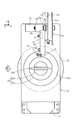
- FIG. 1 is a front view showing a winding device according to an embodiment of the present invention.
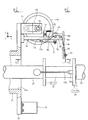
- FIG. 2 is a sectional view taken along line II-II of FIG.
- FIG. 3 is a view of the flyer as viewed from the direction III in FIG.
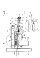
- FIG. 4 is a sectional view taken along line IV-IV of FIG.
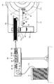
- FIG. 5 is a sectional view taken along line VV of FIG.
- FIG. 6 is an enlarged cross-sectional view of a portion VI in FIG.
- FIG. 7 is an enlarged perspective view of the wire storage tool.
- FIG. 8 is an enlarged sectional view of a portion VIII in FIG. 4, showing a mechanism for detachably attaching the wire storage tool to the flyer.
- FIG. 1 is a front view showing a winding device according to an embodiment of the present invention.
- FIG. 2 is a sectional view taken along line II-II of FIG.
- FIG. 3 is a view of the flyer as viewed from the direction III in FIG
- FIG. 9 is a diagram illustrating a state in which a wire is wound around a wire storage tool attached to a flyer.
- FIG. 10A is a diagram showing a state in which a wire is wound around one of a pair of wire storage tools removed from a flyer.
- FIG. 10B is a diagram illustrating a state in which the wire is wound around the other of the pair of wire storage tools removed from the flyer.
- FIG. 11 is a conceptual diagram showing a state in which a pair of flyers are rotated in opposite directions to simultaneously wind the wire fed from both wire storage tools around the core.
- FIG. 12A is a conceptual diagram showing a state in which a wire fed from a wire storage tool of one flyer is wound around a core.
- FIG. 12B is a conceptual diagram showing a state in which a wire fed from a wire storage tool of one flyer is wound around a core, and then a wire fed from a wire storage tool of the other flyer is wound around a core.
- FIG. 13A is a conceptual diagram showing a state in which the core and one flyer are simultaneously rotated to wind the wire fed from the wire accumulator of the other flyer around the core.
- FIG. 13B shows that the core and one flyer are simultaneously rotated to wind the wire fed from the wire accumulator of the other flyer around the core, and then the other flyer is rotated together with the core to stop the rotation.
- It is a conceptual diagram which shows a mode that the wire unwound from the wire storage tool of one flyer is wound around a core.
- FIG. 1 shows a winding device 10 according to an embodiment of the present invention.
- three axes of X, Y, and Z orthogonal to each other are set.
- the X-axis extends in a substantially horizontal front-rear direction
- the Y-axis extends in a substantially horizontal lateral direction
- the Z-axis extends in a substantially vertical direction.
- the winding device 10 includes a winding core 12 around which a wire 11 is wound, and a winding core servomotor 16 serving as a winding core rotating unit that rotates the winding core 12 around an axis.
- the core 12 has a cylindrical main body 12b having a circular cross section, and a flange 12c provided on the base end side of the main body 12b.
- the flange 12c has a larger diameter than the main body 12b.
- An extension shaft 17 is coaxially provided on a rotation shaft 16a of the core servomotor 16 via a joint 16b.
- a base end of the winding core 12 on the flange 12c side is coaxially provided at a distal end of the extension shaft 17.
- the winding core servomotor 16 is attached to the base 9 via a pedestal 16 c with its rotating shaft 16 a directed in the X-axis direction. Therefore, when the core servomotor 16 is driven, the core 12 in which the base end is attached to the rotation shaft 16a of the core servomotor 16 via the extension shaft 17 can rotate with the X axis as the rotation axis. is there.
- the winding device 10 includes a support 21 that supports the distal end of the core 12 whose base end is supported by the extension shaft 17.
- the support 21 includes a supporting servomotor 22, a pressing shaft 23 provided coaxially to a rotating shaft 22 a of the supporting servomotor 22 via a joint 22 b, and the supporting shaft 23 together with the supporting servomotor 22.
- the moving mechanism 25 in this embodiment includes a guide rail 27 disposed on the base 9 in parallel with the rotation axis (X axis) of the core 12, a moving body 26 guided by the guide rail 27,
- the motor 9 includes a movement motor 28 provided on the table 9 and a ball screw 29 connected to a rotation shaft 28 a of the movement motor 28.
- the moving motor 28 is provided such that its rotating shaft 28 a is parallel to the guide rail 27.
- the ball screw 29 extends in the rotation axis direction (X-axis direction) of the core 12 and is screwed to the moving body 26.
- the supporting servomotor 22 is attached to the moving body 26 via the pedestal 22c such that the holding shaft 23 is oriented in the X-axis direction and the tip of the holding shaft 23 faces the tip of the core 12.
- the moving mechanism 25 when the moving motor 28 is driven, the ball screw 29 rotates, and the moving body 26 screwed to the ball screw 29 is guided by the guide rail 27 and moves. Then, the supporting servomotor 22 mounted on the moving body 26 also moves in the rotation axis direction (X-axis direction) of the core 12 together with the moving body 26.
- the holding shaft 23 provided on the supporting servomotor 22 so as to be coaxial with the core 12 is formed. It approaches the core 12.
- the holding member 24 provided at the tip of the holding shaft 23 is configured to be able to contact the tip of the core 12 (FIG. 3).
- a hole 23a is formed at the tip of the holding shaft 23 in the axial direction from the tip edge.
- the holding member 24 has an insertion portion 24 a inserted into the hole 23 a and a holding portion 24 b formed to have a larger diameter than the holding shaft 23 and to actually contact the tip of the core 12.
- a long hole 23b extending in the axial direction is formed at the distal end of the pressing shaft 23 in the peripheral wall thereof. The long hole 23b is formed to penetrate from the outer periphery of the holding shaft 23 to the inner periphery of the hole 23a.
- the coil spring 23c is inserted into the hole 23a.
- An insertion portion 24a is further inserted into the hole 23a so as to compress the coil spring 23c.
- a male screw 23d is inserted into the elongated hole 23b, and is screwed to the insertion portion 24a of the holding member 24.
- the holding member 24 is provided at the tip of the holding shaft 23 so as to be movable in the axial direction within the moving range of the male screw 23d in the long hole 23b.
- the coil spring 23c urges the retainer 24 in a direction to protrude from the hole 23a by a force to be extended.
- the male screw 23d contacts the hole edge of the long hole 23b to prevent the insertion portion 24a of the holding member 24 from coming off the hole 23a.
- a slit 12 a extending in the axial direction from the tip is formed so as to extend through the core 12 and extend to the extension shaft 17.
- the pressing portion 24b is formed with a ridge 24c that prohibits the slit 12a from entering the slit 12a and reducing the width of the slit 12a. Then, when the holding shaft 23 approaches the core 12 and the holding member 24 provided at the tip of the holding shaft 23 comes into contact with the tip of the core 12, as shown in FIG. It is prohibited to enter the slit 12a and narrow the width of the slit 12a.
- the pressing portion 24b is in contact with the leading end of the core 12 to limit the winding width of the wire 11 in the core 12 that can be wound.
- the holding tool 24 supports the leading end of the core 12.
- the supporting servomotor 22 (FIG. 1) rotates the presser 24 in synchronization with the rotation of the core 12 so that the relative positional relationship between the core 12 and the presser 24 does not change.
- the moving mechanism 25 is configured such that the moving distance of the moving body 26 is longer than the winding width of the core 12, that is, the length of the main body 12b of the core 12.
- the winding device 10 includes a pair of flyers 31, 31 arranged so as to sandwich the winding core 12 from the axial direction.
- a sliding cylinder 32 is fitted into the extension shaft 17 having the base end of the core 12 attached to the distal end so as to be movable in the longitudinal direction with respect to the extension shaft 17.
- a sliding cylinder 32 is fitted into the holding shaft 23 that supports the tip of the core 12 so as to be movable in the longitudinal direction with respect to the holding shaft 23.
- a rotating cylinder 34 is fitted into the respective sliding cylinders 32 of the extension shaft 17 and the holding shaft 23 via a bearing 33.
- the flyers 31 are attached to the ends of the rotary cylinders 34 on the core 12 side, respectively.
- the pair of flyers 31 and 31 are attached to the rotating cylinder 34 fitted to the extension shaft 17 and the holding shaft 23 via the sliding cylinder 32.
- Each of the pair of flyers 31, 31 is provided so as to be rotatable around the rotation axis (X axis) of the core 12 and to be movable in the direction of the rotation axis.
- the winding device 10 of the present embodiment having such a pair of flyers 31, 31 synchronizes or separates one or both of the pair of flyers 31, 31 around the axis of the core 12 as a rotation center.
- the apparatus includes a pair of rotary servomotors 51 constituting a flyer rotating means for rotating, and a traverse mechanism 41 for moving one or both of the pair of flyers 31, 31 in the axial direction with respect to the core 12.
- the traverse mechanism 41 is configured so that the pair of flyers 31, 31 can be moved separately.
- the traverse mechanism 41 includes a plurality of support walls 43 that pivotally support the pair of rotary cylinders 34 via bearings 42, a pair of movable tables 44 on which the plurality of support walls 43 are erected, and a rotating shaft of the core 12.
- a pair of guide rails 45 arranged on the base 9 so as to be parallel to the moving table 44
- a pair of traverse motors 46 provided on the base 9, and a rotation shaft 46a of the traverse motor 46.
- a pair of ball screws 47 A pair of ball screws 47.
- the traverse motor 46 is provided such that its rotating shaft 46a is parallel to the guide rail 45.
- the ball screw 47 extends in the rotation axis direction (X-axis direction) of the core 12 and is screwed to the movable base 44.
- the traverse mechanism 41 In the traverse mechanism 41, when the traverse motor 46 is driven, the ball screw 47 is rotated, and the movable base 44 screwed to the ball screw 47 is guided and moved by the guide rail 45. Then, the support wall 43 erected on the movable base 44 also moves in the same direction, and the rotary cylinder 34 pivotally supported by the support wall 43 moves in the axial direction (X-axis direction) of the core 12 together with the flyer 31. .
- the traverse mechanism 41 since the traverse motor 46 and the like are provided for each of the pair of flyers 31, 31, the pair of flyers 31, 31 can be moved separately.
- the traverse mechanism 41 can also move the pair of flyers 31, 31 at the same time.
- the winding device 10 includes the pair of rotation servomotors 51 that can separately rotate the pair of flyers 31, 31 as the flyer rotating unit that rotates the pair of flyers 31, 31.
- the pair of rotation servomotors 51 are provided on the respective moving tables 44 adjacent to the respective rotating cylinders 34.
- a drive pulley 52 is provided on the rotation shaft 51 a of the rotation servomotor 51, and a driven pulley 53 is provided at a position corresponding to the drive pulley 52 in the rotary cylinder 34.
- a belt 54 is provided between the drive pulley 52 of the rotation servomotor 51 and the pulley 53 of the rotary cylinder 34.
- the rotation servomotor 51 which is a flyer rotation means
- the rotation shaft 51a together with the driving pulley 52
- the rotation is transmitted to the rotation cylinder 34 via the belt 54 and the driven pulley 53
- the rotation cylinder 34 rotates. I do.
- the rotating cylinder 34 rotates, the flyer 31 provided on the rotating cylinder 34 rotates around the core 12 as a rotation center.
- the rotation servomotor 51 is provided for each of the pair of flyers 31, 31, the pair of flyers 31, 31 can be separately rotated.
- the pair of rotary servomotors 51 can also rotate the pair of flyers 31, 31 in synchronization.
- the pair of flyers 31, 31 are provided on the pair of rotating cylinders 34 on the sides facing each other.
- the flyers 31, 31 provided on the pair of rotary cylinders 34, respectively, are rectangular plate members along a plane orthogonal to the rotation axis of the core 12, and the extension shaft 17 or the holding shaft 23 can be inserted into the center thereof.
- a round hole 31a is formed.
- a wire storing tool 61 for storing the wire 11 wound around the core 12 and the wire storing tool 61 is fed from the wire storing tool 61.
- a tension device 71 for applying tension to the wire 11 guided to the winding core 12.
- a control unit 77 having a central processing unit built in a hard case is attached to the other end in the long side direction of the pair of fryers 31 having a rectangular shape, as a feeding speed control means described later.
- the wire storage tool 61 provided on one of the pair of fryers 31, 31 and the wire storage tool 61 provided on the other have the same structure. Further, the tension device 71 provided on one of the pair of flyers 31 and 31 has the same structure as the tension device 71 provided on the other. For this reason, the storage wire 61 and the tension device 71 provided in the flyer 31 in which the extension shaft 17 is inserted into the round hole 31a among the pair of flyers 31 and 31 will be described as a representative, and the holding shaft 23 is inserted into the round hole 31a. The description of the wire accumulator 61 and the tension device 71 provided in the flyer 31 through which is inserted is omitted.
- the wire storage tool 61 includes a bottomed tubular winding material 61a around which the wire 11 is actually wound, and an axial direction around the winding material 61a.
- This is a plastic spool having a pair of flange portions 61b and 61c formed apart from each other.
- the wire accumulator 61 has a relatively large diameter so that a relatively long wire 11 can be wound.
- a coupling shaft 61d is formed on the wire storage tool 61 so as to protrude on the central axis thereof.
- An annular groove 61e is formed at the tip of the coupling shaft 61d in the circumferential direction.
- a pivot support 62 is provided on the outer peripheral portion of the flyer 31 in parallel with the core 12, and the pivot support 62 is provided in the rotational tangential direction of the flyer 31.
- An extending mounting shaft 63 is pivotally supported.
- a lock mechanism 64 (FIG. 8) is provided at the tip of the mounting shaft 63.
- the lock mechanism 64 in this embodiment includes a cylindrical body 64a having a coupling hole 64b into which the coupling shaft 61d of the wire storage tool 61 can be inserted, and a cup provided in the cylindrical body 64a.
- a lock member 64c that engages with the annular groove 61e formed on the ring shaft 61d, a spring 64d that presses the lock member 64c against the annular groove 61e, and the like are provided.
- the cylindrical body 64 a is provided coaxially at the tip of the mounting shaft 63.
- a slit 64e extending in the axial direction from the end of the cylindrical body 64a is formed.
- the coupling shaft 61d is formed with a projection 61k that can enter the slit 64e. For this reason, when the coupling shaft 61d is inserted into the coupling hole 64b against the urging force of the spring 64d, the locking member 64c is pressed against the annular groove 61e by the urging force of the spring 64d, so that the coupling shaft 61d. From the coupling hole 64b.
- the wire storage tool 61 is detachably attached to the attachment shaft 63 via the lock mechanism 64.
- the wire storage tool 61 rotates together with the mounting shaft 63 while being mounted on the mounting shaft 63, and is prohibited from rotating independently of the mounting shaft 63.
- a feeding motor 72 capable of controlling the rotation speed of the mounting shaft 63 is mounted on the pivot support 62 such that the rotating shaft 72 a is parallel to the mounting shaft 63.
- a driven pulley 73a is provided on the mounting shaft 63 on which the lock mechanism 64 is provided, and a driving pulley 73b is provided on the rotating shaft 72a of the feeding motor 72.
- a belt 73c is provided between the driven pulley 73a and the driving pulley 73b.
- the tension device 71 includes the above-described feeding motor 72, a tension bar 74 having a turning pulley 74 a as a wire guide provided at a distal end and a base end pivotally supported, and a tension bar 74.
- Coil spring 75 which is an elastic member that generates an elastic force corresponding to the rotation angle of the motor
- linear sensor 76 which is a detecting means for detecting the rotation angle of tension bar 74
- a control unit 77 (FIG. 3) which is a feeding speed control means for controlling the feeding speed of the wire 11 so that the angle becomes a predetermined angle.
- a mounting base 78 is provided on the outer periphery of the flyer 31 in the vicinity of the pivot support 62 and adjacent to the feed motor 72.
- the mounting base 78 is erected on the outer periphery of the flyer 31 so as to be parallel to the pivot base 62.
- a base end of a tension bar 74 is pivotally supported at an intermediate portion of the mounting base 78.
- the tension bar 74 is pivotally supported so as to cross the mount 78.
- a turning pulley 74a serving as a wire guide is pivotally supported.
- a plurality of pulleys 79 around which the wire material 11 unwound from the wire storage tool 61 is wound are pivotally supported on the tip side of the mounting base 78 beyond the tension bar 74.
- the wire 11 is guided by the plurality of pulleys 79 toward the base end side of the mounting base 78, is wound around the turning pulley 74 a so as to be folded, and then returns to the distal end side of the mounting base 78 from the turning pulley 74 a.
- An extension piece 80 extending toward the core 12 is attached to the tip of the attachment base 78.
- An extension pulley 81 that guides the wire 11 to the core 12 is provided at an end of the extension piece 80 on the core 12 side.
- a plurality of guide pulleys 82 for feeding out the wire 11 folded by the deflecting pulley 74 a and guiding it to the pulley 81 are pivotally supported on the mounting base 78 and the extension piece 80.
- the coil spring 75 is an elastic member that urges the turning pulley 74 a toward the base end of the mounting base 78.
- One end of the coil spring 75 is attached to the proximal end side of the tension bar 74, and the other end is attached to the distal end side of the attachment base 78 via an attachment member 83.
- the coil spring 75 is provided along the mount 78.
- the fixed position of the other end of the coil spring 75 attached to the attachment base 78 via the attachment member 83 can be changed.
- the coil spring 75 generates an elastic force according to the rotation angle of the tension bar 74.
- the linear sensor 76 which is a detecting means for detecting the rotation angle of the tension bar 74, includes a sensor rod 76a and a sensor head 76b.
- the sensor rod 76a is attached to the tension bar 74 and moves with the rotation of the tension bar 74.
- the sensor head 76b is provided on the mounting base 78 and is configured to output a voltage based on the position of the sensor rod 76a.
- the linear sensor 76 is connected to a control unit (delivery speed control means) 77 (FIG. 3), and a signal detected by the linear sensor 76 is output to the control unit (delivery speed control means) 77.
- a control unit that maintains the balance with the storage device 61 and the tension device 71 is provided at the end of the flyer 31 on the opposite side to the side where the wire storage device 61 and the tension device 71 are provided.
- 77 is provided at the end of the flyer 31 on the opposite side to the side where the wire storage device 61 and the tension device 71 are provided.
- the control unit 77 has a hard case and a central processing unit built in the hard case.
- the central processing unit of the control unit 77 calculates the rotation angle of the tension bar 74 based on the detection signal of the linear sensor 76, and adjusts the rotation speed of the rotation shaft 72a of the delivery motor 72 so that the angle becomes a predetermined angle. Control.
- the central processing unit of the control unit 77 controls the rotation speed of the rotating shaft 72 a of the feeding motor 72 to adjust the rotation speed of the wire storage tool 61, and is released from the wire storage tool 61 to the core 12. It is configured such that the feeding speed of the wire 11 going forward is matched with the winding speed of the wire 11 around the core 12. As described above, the control unit 77 functions as a payout speed control unit that controls the payout speed of the wire 11 that is fed from the wire storage tool 61 toward the core 12.
- the coil spring 75 urges the tip of the mounting base 78 from which the wire 11 is fed toward the winding core 12 in a direction to separate the turning pulley 74a as a wire guide, and is wound around the turning pulley 74a.
- the wire 11 is stretched so that a predetermined tension is applied to the wire 11.
- the control unit 77 serving as the feeding speed control means includes a feeding speed (feeding amount) of the wire 11 that is unwound from the storage wire tool 61 serving as a supply source of the wire 11 and is fed toward the winding core 12,
- the rotation speed of the feeding motor 72 is controlled so that the winding speed (winding amount) of the wire 11 is balanced with that in the above, and the deflecting pulley 74 a around which the wire 11 is wound is urged by the coil spring 75.
- the tension bar 74 is configured to be held at a predetermined rotation angle.
- the spring force of the coil spring 75 acts on the wire 11 in accordance with the rotation angle of the tension bar 74, and a predetermined tension based on this spring force is applied. For this reason, in the winding operation of winding the wire 11 around the winding core 12, if the winding speed (winding amount) of the wire 11 around the winding core 12 changes, the rotation angle of the tension bar 74 changes, and the wire rod 11 changes. The tension applied to 11 fluctuates.
- the control unit (delivery speed control means) 77 receiving such feedback controls the rotation speed of the feeding motor 72 so that the rotation angle of the tension bar 74 returns to a predetermined angle, and controls the rotation speed of the wire storage tool 61. Is adjusted so that the feeding speed of the wire 11 released from the wire accumulating tool 61 toward the winding core 12 is matched with the winding speed on the winding core 12. Thereby, the rotation angle of the tension bar 74 returns to the predetermined angle, and the tension applied to the wire 11 returns to the predetermined value.
- the mounting position of the mounting member 83 on the mounting base 78 is changed. Accordingly, the length of the coil spring 75 when the tension bar 74 is at a predetermined rotation angle can be changed, and the spring force exerted on the tension bar 74 from the coil spring 75 can be adjusted. The desired tension can be obtained.
- a wire storage tool 61 for storing the wire rod 11 wound around the core 12 is provided in each of the pair of fryers 31.
- the winding method of the wire 11 using the winding device 10 includes a wire storing step of winding the wire 11 of a required length around a pair of wire storing tools 61 from both sides, and either one of the pair of flyers 31, 31 or
- the wire material 11 fed from the wire storage tool 61 is wound around the core 12 by rotating both of them synchronously or separately about the axis of the core 12 as the center of rotation, and the winding start end and the winding end are both from the outermost layer. Winding the formed coil around the winding core 12.
- the wire storage tool 61 is detachably provided on the pair of flyers 31, 31, respectively. For this reason, it is also possible to perform the above-described wire storing step in a state where the wire storing tool 61 is detached from the pair of fryers 31, 31.
- the wire storing step is performed using the wire storing tool 61 detached from the flyers 31, 31, a pair of the wire storing tools 61 in which the wire 11 is wound from both ends between the wire storing step and the winding step. Is attached to a pair of flyers 31 of the winding device 10.
- the wire 11 having a required length is wound around a pair of wire storing tools 61 from both sides. Prior to the work of winding the wire 11 around the wire storage tool 61, a pair of wire storage tools 61 and the wire 11 having a required length are prepared.
- the necessary length of the wire 11 is a wire 11 having a length necessary to form a single coil to be obtained.
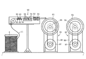
- FIG. 9 shows a case where a calibrator 90 for removing a bending habit of the wire 11 unraveled from the drum 8 is used.
- the calibrating machine 90 includes a cutting machine 91 that cuts the wire 11, a wire gripper 92 that grips the wire 11, a plurality of vertical calibration rollers 93 for removing a vertical bending habit of the wire 11, And a plurality of lateral calibration rollers 94 for removing the lateral bending habit of the above.
- the wire 11 is wound around the wire accumulating tool 61 after the bending habit is removed by passing between the plurality of rollers 93 and 94 of the calibrator 90.
- the cutting machine 91 holds the wire 11 fed from the drum 8 by the wire holding machine 92. Cuts the wire 11. Then, as shown in FIG. 1, the cut end is fixed to the other wire storage tool 61 provided on the other flyer 31. After that, the feeding motor 72 attached to the flyer 31 provided with the other wire storage tool 61 is driven to rotate the other wire storage tool 61. At this time, in the feed-out motor 72 attached to the flyer 31 provided with the one storage device 61, the one storage device 61 is rotated in the opposite direction, and the other storage device 61 is rotated. Is unwound from the one wire storage tool 61 and fed out.
- the spool rotating machine 95 provided separately from the winding device 10 is used.
- the wire rod 11 is wound around the wire storage tool 61.
- the spool rotating machine 95 shown in the figure has a base plate 98 provided with a rotating body 96 to which the wire storage tool 61 is attached and a motor 97 for rotating the rotating body 96.
- a storage wire 61 is attached to the rotating body 96, and the end of the wire 11 unraveled from the drum 8 is fixed to the storage wire 61, and then the motor 97 is driven to rotate the storage wire 61.
- the wire 11 unwound from the drum 8 is wound around the wire 61.
- Two spool rotating machines 95 are used adjacent to each other.
- One of the spooling tools 61 is attached to a rotating body 96 of one spool rotating machine 95, and the other is attached to a rotating body 96 of the other spool rotating machine 95.
- the storage wire tool 61 is attached. After the wire 11 having a required length is wound around one of the wire accumulators 61, the wire 11 pulled out from the drum 8 is gripped by the wire gripper 92 of the calibrator 90, and the wire 11 is cut by the cutting machine 91. Disconnect.
- the spool rotating machine 95 and the calibrator 90 described above are an example of a device for winding the wire 11 around the wire storage device 61, and the device for winding the wire 11 around the wire storage device 61 is limited to this example. Not something.
- any device may be used as long as the wire 11 having a required length can be wound around the wire storing tool 61 detached from the pair of fryers 31, 31.
- the wire storing tool attaching step is a necessary step when the wire storing step is performed in a state where the wire storing tool 61 is detached from the pair of fryers 31, 31.
- a pair of wire storage devices 61 around which the wire 11 is wound from both ends are mounted on a pair of flyers 31 of the winding device 10.
- the wire storage tool 61 is provided with a coupling shaft 61d, and a lock mechanism 64 is provided at the tip of the mounting shaft 63 in the flyer 31.
- a lock mechanism 64 is provided at the tip of the mounting shaft 63 in the flyer 31.
- the lock member 64c When the coupling shaft 61d is inserted into the coupling hole 64b, the lock member 64c is pressed against the annular groove 61e by the urging force of the spring 64d. This prevents the coupling shaft 61d from coming out of the coupling hole 64b.
- the lock mechanism 64 is configured such that the projection 61k enters the slit 64e with the coupling shaft 61d inserted into the coupling hole 64b. Therefore, the wire storage tool 61 is non-rotatably mounted on the mounting shaft 63.
- Winding process> In the winding step, one or both of the pair of flyers 31 and 31 are rotated synchronously or separately about the center axis of the winding core 12 as a center of rotation, and the wire 11 fed from the wire storage tool 61 is wound into the winding core 12. And a coil whose winding start end and winding end are both drawn out of the outermost layer is formed around the winding core 12.
- the wire storage tools 61 for storing the wire 11 wound around the winding core 12 are provided on the pair of fryers 31 respectively. Therefore, the relatively long wire 11 is wound around the core 12 by storing the relatively long wire 11 in the wire accumulating tool 61 and rotating the pair of flyers 31 with respect to the core 12. And a relatively large coil can be manufactured. Therefore, according to the present embodiment, it is possible to provide a winding device 10 capable of manufacturing a large-sized coil having a relatively large number of turns, and a winding method using the same.
- ⁇ Whether or not to rotate the core 12 and which of the pair of flyers 31 and 31 to rotate depends on the specification of the coil to be obtained. For example, as shown in FIG. 11, when both flyers 31 are simultaneously rotated in the opposite directions about the rotation axis of the core 12 without rotating the core 12, the accumulators provided on both the flyers 31 are rotated. The wires 11 are respectively unreeled from the wires 61 and wound around the core 12 at the same time. At this time, if the pair of flyers 31, 31 is reciprocated in the axial direction of the core 12 by the traverse mechanism 41, the wire 11 can be aligned and wound around the core 12 in a plurality of layers.
- the wire rod 11 may be wound around the core 12 by rotating one flyer 31 and then rotating the other flyer 31. It can.
- the wire 11 fed from the wire storage tool 61 provided on one of the flyers 31 is wound around the core 12.
- the rotation of the one flyer 31 is stopped.
- the other flyer 31 is rotated about the axis of the core 12 as a rotation center.
- the wire 11 fed from the wire storage tool 61 provided on the other flyer 31 is further wound on the previously wound wire 11.
- the pair of flyers 31 by allowing the pair of flyers 31 to be separately rotatable, the specifications for winding the wire 11 around the core 12 can be diversified. Therefore, it is possible to easily form a plurality of types of coils around the winding core 12 in which both the winding start end and the winding end end are led out of the outermost layer.
- the winding device 10 includes a core servomotor 16 as a core rotating means for rotating the core 12 (FIG. 1). Therefore, when the core 12 is rotated at the same speed in the same direction at the same time as the rotation of the flyer 31, the relative positional relationship between the flyer 31 and the core 12 does not change.
- the wire 11 is not wound around the winding core 12 from the wire storage tool 61 of the flyer 31 that rotates together with the winding core 12, and the flyer 31 that does not rotate with the winding core 12, for example, in a stopped state.
- the wire 11 fed from the wire storage tool 61 in the flyer 31 is wound around the rotating core 12.
- the core 12 is rotated by a core servomotor (core rotating means) 16, and one flyer 31 is wound simultaneously with the rotation of the core 12.
- the core 12 is rotated in the same direction and at the same speed.
- the flyer 31 that does not rotate together with the core 12, for example, the wire 11 drawn out from the wire accumulator 61 in the stopped flyer 31 is wound around the core 12.
- the winding has an arbitrary number of windings and an arbitrary number of layers, and the winding start end and the winding end are both from the outermost layer. It is possible to easily form the plurality of types of derived coils around the winding core 12. That is, it is possible to further diversify the specifications for winding the wire 11 around the core 12.
- the tension device 71 is provided on each of the pair of fryers 31, 31 together with the wire storage tool 61. For this reason, it becomes possible to wind the wire 11 around the winding core 12 with a predetermined tension, and it is possible to avoid the occurrence of winding unevenness due to different tensions in the winding operation of the wire 11.
- the flyer 31 to which the wire storage tool 61 is attached is rotated in the winding step, so that the wire storage step of storing the wire 11 in the wire storage tool 61 is performed. It will be performed before the line process.
- the wire storage tool 61 is detachably provided on the pair of flyers 31. For this reason, as shown in FIGS. 10A and 10B, a wire storing step is performed using the wire storing tool 61 detached from the flyer 31, and then a wire storing tool attaching step of mounting the wire storing tool 61 to the flyer 31 is performed. Then, as shown in FIGS. 11 to 13B, a winding step of winding the wire 11 fed from the wire accumulating tool 61 around the core 12 may be performed at the same time as the winding step. It is possible to perform the wire storing step using the wire storing tool 61 of the first embodiment.
- the winding process and the wire storage process can be performed simultaneously. Therefore, the wire storing step cannot be performed simultaneously with the winding step, and the coil can be manufactured more quickly than in the related art in which the steps need to be continued.
- a bobbin (not shown) may be fitted to the core 12 and the wire 11 may be wound around the bobbin to form a coil.
- the mechanism for detachably attaching the wire storage tool 61 to the flyers 31, 31 includes the coupling shaft 61d provided on the wire storage tool 61 and the lock mechanism 64 for mounting the coupling shaft 61d.
- the mounting shaft 63 provided with the lock mechanism 64 is pivotally supported by the flyer 31 has been described, but the present invention is not limited to this.
- the storage wire 61 can be detachably provided to the flyers 31, 31, the storage wire 61 may be detachably attached to the flyers 31, 31 by another mechanism, for example, by screwing.
- the winding device 10 includes one of the core 12 around which the wire 11 is wound, the pair of flyers 31 arranged to sandwich the core 12 from the axial direction, and one of the pair of flyers 31.
- a flyer rotating means (rotary servomotor 51) for rotating both of them about the axis of the core 12 and a storage for storing the wire 11 which is detachably provided on the pair of fliers 31 and which is wound around the core 12 respectively.
- It comprises a wire 61 and a tension device 71 provided on each of the pair of fryers 31 to apply tension to the wire 11 fed from the wire accumulator 61 and guided to the core 12.
- the wire storage tools 61 for storing the wire rod 11 wound around the core 12 are provided on the pair of flyers 31 respectively. Accordingly, the relatively long wire 11 is wound around the core 12 by storing the relatively long wire 11 in the wire storage tool 61 and rotating the pair of flyers 31 with respect to the core 12. It is possible to manufacture a large coil having a relatively large number of turns.
- the winding device 10 includes a traverse mechanism 41 that moves one or both of the pair of flyers 31 in the axial direction with respect to the core 12.
- the winding device 10 can also include a core rotating means (core servo motor 16) for rotating the core 12 about an axis.
- the core 12 is supported on the base end side, and It is preferable to provide a support 21 for supporting the distal end side of the support 12.
- the provision of the traverse mechanism 41 and the winding core rotating means also enables the winding of the wire rods 11 and the like, and the variety of windings can be achieved.
- the winding method using the winding device 10 includes a wire storing process of winding a wire 11 of a required length around a pair of wire storage tools 61 from both sides, and a pair of wires storing the wire 11 from both ends.
- Storage device mounting step of mounting the tool 61 to the pair of flyers 31 of the winding device 10, and pulling out one or both of the pair of flyers 31 from the storage device 61 by rotating one or both of them around the axis of the core 12. Winding the wire 11 to be wound around the winding core 12, and forming a coil around the winding core 12 with both the winding start end and the winding end drawn from the outermost layer.
- a large coil having a relatively large number of turns can be manufactured.
- the wire storing step of storing the relatively long wire 11 in the wire storage tool 61 is performed by actually storing the wire 11 on the winding core 12. Is carried out before the winding step of winding.
- the wire storage tool 61 is detachably provided on the pair of flyers 31. For this reason, the wire storing process is performed using the wire storing tool 61 detached from the flyer 31, and then, the wire storing tool mounting process of mounting the wire storing tool 61 to the flyer 31 is performed, and further thereafter, the wire storing tool 61 is removed from the wire storing tool 61. If a winding step of winding the fed wire 11 around the winding core 12 is performed, it is possible to perform a wire storing step using another wire storing tool 61 simultaneously with the winding step.
- the wire storage process and the winding process can be performed simultaneously. Instead, it is possible to manufacture a coil more quickly than in the related art in which the steps need to be continued.
- the winding device 10 capable of manufacturing a large-sized coil having a relatively large number of turns, and a winding method using the same.
- a winding device 10 capable of manufacturing a coil quickly and a winding method using the same. That is, it is possible to provide the winding device 10 capable of rapidly manufacturing a large coil having a relatively large number of turns and a winding method using the same.
Landscapes
- Engineering & Computer Science (AREA)
- Power Engineering (AREA)
- Manufacturing & Machinery (AREA)
- Manufacture Of Motors, Generators (AREA)
- Coil Winding Methods And Apparatuses (AREA)
Abstract
巻線装置(10)は、線材(11)が巻回される巻芯(12)と、巻芯(12)を軸方向から挟むように配置された一対のフライヤ(31)と、一対のフライヤ(31)のいずれか一方又は双方を巻芯(12)の軸を回転中心として回転させるフライヤ回転手段(51)と、一対のフライヤ(31)にそれぞれ着脱自在に設けられ巻芯(12)に巻回される線材(11)を蓄える蓄線具(61)と、一対のフライヤ(31)にそれぞれ設けられ蓄線具(61)から繰り出されて巻芯(12)に導かれる線材(11)にテンションを付与するテンション装置(71)と、を備える。
Description
本発明は、コイルの巻始め端と巻終わり端が共にコイルの最外周層に来るように巻線する巻線装置及びそれを用いた巻線方法に関する。
モータの小型化に対応したコイルとして、線材が緊密に巻回されて巻層の間に無用の間隙が形成されないようにするとともに、線材の巻始め端と巻終わり端とが同一の巻層に配線されるようにした、いわゆるアルファ巻(又は、「外外巻」ともいう。)コイルが知られている。
このアルファ巻コイルとして、線材を渦巻き状に巻回した第一、第二コイルと、この第一、第二コイルの内周端部どうしを結ぶ内側渡り線とを有する二列渦巻きコイルが知られている。そして、このような二列渦巻きコイルの製造装置として、線材の2本分の隙間を隔てて対向して巻芯の周囲を相互に逆方向に回転する第一及び第二のホイールと、第一のホイールのガイド溝又は穴に向けて線材を繰出す線材供給部と、線材を巻回状態で蓄えかつ第二のホイールのガイド溝又は穴に向けてその線材を繰出す蓄線部と、を備える装置が提案されている(JPH10-154626Aの段落番号「0010」、「0011」及び「0019」参照)。
この製造装置では、巻線の前段階として、線材供給部から供給される線材を蓄線部に蓄え、その後に、線材供給部と蓄線部の間の線材の任意の位置を巻始めとし、第一及び第二のホイールを相互に逆方向に回転させる。これにより、その巻始めの位置から両側に延びる線材を巻芯に同時に相互に逆方向に巻回して、その巻芯の軸方向に2層となる巻線部をその巻芯の外周に形成することができる。
このように、この製造装置では、各巻線部の外周から線材を導出することにより、線材の巻始め端と巻終わり端とが最外周の同一の巻層から引出された二列渦巻きコイルを比較的容易に製造することができる。
しかし、JPH10-154626Aにおけるコイルの製造装置では、線材供給部から供給される線材を蓄線部に蓄えた後に、第一及び第二のホイールを相互に逆方向に回転させることにより、それらの双方から繰り出される線材を巻芯に巻回する。このため、得られるコイルの大きさは、蓄線部から供給しうる線材の長さに制限され、比較的長い線材を用いた比較的大きなコイルの製造が困難である。
比較的大きなコイルを得るために、蓄線部に比較的長い線材を蓄線させることが考えられる。しかしながら、蓄線部に比較的長い線材を蓄線させると、実際の巻線以前に行われる蓄線工程に費やす時間が拡大して、速やかにコイルを製造することが困難になる。
このため、JPH10-154626Aにおけるコイルの製造装置において製造し得るコイルは、同一の巻数からなる第一及び第二コイルが内側渡り線により連結された二列渦巻きコイルのような、比較的小型のものに限定されるという問題がある。
本発明の目的は、巻数が比較的多い大型のコイルを迅速に製造し得る巻線装置及びそれを用いた巻線方法を提供することにある。
本発明のある態様によれば、巻線装置であって、線材が巻回される巻芯と、前記巻芯を軸方向から挟むように配置された一対のフライヤと、前記一対のフライヤのいずれか一方又は双方を回転させるフライヤ回転手段と、前記一対のフライヤにそれぞれ着脱自在に設けられ前記巻芯に巻回される前記線材を蓄える蓄線具と、前記一対のフライヤにそれぞれ設けられ前記蓄線具から繰り出されて前記巻芯に導かれる前記線材にテンションを付与するテンション装置と、を備える。
本発明の別の態様によれば、上記巻線装置を用いた巻線方法であって、必要な長さの線材を両側から一対の前記蓄線具に巻きつける蓄線工程と、前記線材が両端から巻回された一対の前記蓄線具を前記巻線装置の前記一対のフライヤに取付ける蓄線具取付工程と、前記一対のフライヤのいずれか一方又は双方を前記巻芯の軸を回転中心として回転させて前記蓄線具から繰り出される前記線材を前記巻芯に巻回し、巻始め端と巻終わり端が共に最外周層から導き出されたコイルを前記巻芯の周囲に形成する巻線工程と、を備える。
本発明の実施形態を図面に基づいて説明する。
図1に、本発明の実施形態に係る巻線装置10を示す。ここで、互いに直交するX,Y,Zの3軸を設定する。X軸は略水平前後方向、Y軸は略水平横方向、Z軸は略垂直方向に延びるものとし、巻線装置10の構成を説明する。
図1に示すように、巻線装置10は、線材11が巻回される巻芯12と、その巻芯12を軸回りで回転させる巻芯回転手段としての巻芯用サーボモータ16と、を備える。巻芯12は、断面が円形を成す円柱状の本体部12bと、その本体部12bの基端側に設けられるフランジ12cと、を有する。フランジ12cは、本体部12bよりも大径である。巻芯用サーボモータ16の回転軸16aには、ジョイント16bを介して延長軸17が同軸に設けられる。延長軸17の先端には、巻芯12のフランジ12c側の基端が同軸に設けられる。
巻芯用サーボモータ16は、その回転軸16aをX軸方向に向けて、基台9に台座16cを介して取付けられる。このため、巻芯用サーボモータ16の回転軸16aに延長軸17を介して基端が取付けられた巻芯12は、巻芯用サーボモータ16が駆動すると、X軸を回転軸として回転可能である。
この巻線装置10は、延長軸17に基端側が支持された巻芯12の先端側を支持する支持具21を備える。この支持具21は、支持用サーボモータ22と、その支持用サーボモータ22の回転軸22aにジョイント22bを介して同軸に設けられた押さえ軸23と、その押さえ軸23を支持用サーボモータ22とともにX軸方向に移動させる移動機構25と、を備える。
この実施の形態における移動機構25は、基台9上において巻芯12の回転軸(X軸)と平行に配置されたガイドレール27と、そのガイドレール27に案内される移動体26と、基台9に設けられる移動用モータ28と、移動用モータ28の回転軸28aに連結されるボールネジ29と、を備える。移動用モータ28は、その回転軸28aがガイドレール27と平行となるように設けられる。ボールネジ29は、巻芯12の回転軸方向(X軸方向)に延在し、移動体26に螺合する。支持用サーボモータ22は、押さえ軸23をX軸方向に向けて、押さえ軸23の先端が巻芯12の先端に対向するように、台座22cを介して移動体26に取付けられる。
これにより、この移動機構25では、移動用モータ28が駆動すると、ボールネジ29が回転して、そのボールネジ29に螺合する移動体26がガイドレール27に案内されて移動することになる。すると、移動体26に搭載された支持用サーボモータ22も、その移動体26とともに、巻芯12の回転軸方向(X軸方向)に移動することになる。
移動用モータ28を駆動することによって、支持用サーボモータ22を巻芯12の回転軸方向に移動させると、巻芯12と同軸になるように支持用サーボモータ22に設けられた押さえ軸23が巻芯12に接近する。押さえ軸23の先端に設けられた押さえ具24は、巻芯12の先端に接触可能に構成される(図3)。
図6に詳しく示すように、押さえ軸23の先端には、その先端縁から軸方向に孔23aが形成されている。押さえ具24は、その孔23aに挿入される挿入部24aと、押さえ軸23より大径に形成されて巻芯12の先端に実際に接触する押さえ部24bと、を有する。押さえ軸23の先端には、その周壁において軸方向に延びる長孔23bが形成される。長孔23bは、押さえ軸23の外周から孔23aの内周に貫通して形成される。
孔23aには、コイルスプリング23cが挿入される。孔23aには、コイルスプリング23cを圧縮するように挿入部24aが更に挿入される。長孔23bには雄ねじ23dが挿通されて、押さえ具24における挿入部24aに螺着される。これにより、押さえ軸23の先端には、長孔23bにおける雄ねじ23dの移動範囲内において、押さえ具24が軸方向に移動可能に設けられる。コイルスプリング23cは、伸長しようとする力により押さえ具24を孔23aから突出させる方向に付勢する。雄ねじ23dは、長孔23bの孔縁に当接して、押さえ具24における挿入部24aの孔23aからの離脱を防止する。
この実施の形態における巻芯12には、その先端から軸方向に向かうスリット12aが巻芯12を貫通して延長軸17にまで連続するように形成されている。押さえ部24bには、スリット12aに進入してそのスリット12aの幅が狭まることを禁止する凸条24cが形成されている。そして、押さえ軸23が巻芯12に接近し、押さえ軸23の先端に設けられた押さえ具24が巻芯12の先端に接触すると、図3に示すように、押さえ具24における凸条24cがスリット12aに進入してそのスリット12aの幅が狭まることを禁止する。押さえ部24bは、巻芯12の先端に当接して、巻芯12における線材11の巻回可能な巻幅を制限する。
このようにして、押さえ具24は、巻芯12の先端を支持する。支持用サーボモータ22(図1)は、巻芯12と押さえ具24の相対的な位置関係が変化しないように、巻芯12の回転と同期して押さえ具24を回転させる。
一方、図1に戻って、移動用モータ28がボールネジ29を逆方向に回転させると、移動体26が巻芯12から離間し、巻芯12と押さえ具24との間に隙間が生じる。図6に示すように、押さえ具24における凸条24cがスリット12aから離脱すると、スリット12aの幅が狭まることによる巻芯12の外径の縮小が許容される。
図示しないが、巻芯12に線材11が巻回されると、その線材11はコイルを形成することになる。巻芯12と押さえ具24との間に隙間を生じると、その隙間を介して、巻芯12に巻回された線材11から成るコイルを、外径が縮小した巻芯12から引き抜くことが可能になる。従って、移動機構25は、移動体26の移動距離が、巻芯12の巻幅、即ち、巻芯12の本体部12bの長さよりも長くなるように構成される。
図1に示すように、本実施形態に係る巻線装置10は、巻芯12を軸方向から挟むように配置された一対のフライヤ31,31を備える。以下、具体的に説明する。巻芯12の基端が先端に取付けられた延長軸17には、延長軸17に対して長手方向に移動可能に摺動筒32が嵌入される。同様に、巻芯12の先端を支持する押さえ軸23には、押さえ軸23に対して長手方向に移動可能に摺動筒32が嵌入される。延長軸17及び押さえ軸23のそれぞれの摺動筒32には、ベアリング33を介して回転筒34が嵌入される。そして、それぞれの回転筒34の巻芯12側の端縁にフライヤ31がそれぞれ取付けられる。
このように、一対のフライヤ31,31は、延長軸17及び押さえ軸23に摺動筒32を介して嵌入された回転筒34に取付けられる。一対のフライヤ31,31は、それぞれが巻芯12の回転軸(X軸)を中心として回転可能であって、かつその回転軸方向に移動可能に設けられる。
このような一対のフライヤ31,31を有する本実施形態の巻線装置10は、その一対のフライヤ31,31のいずれか一方又は双方を巻芯12の軸を回転中心として同期して又は別々に回転させるフライヤ回転手段を構成する一対の回転用サーボモータ51と、一対のフライヤ31,31のいずれか一方又は双方を巻芯12に対して軸方向に移動させるトラバース機構41と、を備える。
本実施形態に係るトラバース機構41は、一対のフライヤ31,31を別々に移動可能に構成される。トラバース機構41は、一対の回転筒34をベアリング42を介して枢支する複数の支持壁43と、その複数の支持壁43が立設された一対の移動台44と、巻芯12の回転軸と平行となるように基台9上に配置され移動台44を案内する複数のガイドレール45と、基台9に設けられる一対のトラバースモータ46と、トラバースモータ46の回転軸46aに連結される一対のボールネジ47と、を備える。トラバースモータ46は、その回転軸46aがガイドレール45と平行となるように設けられる。ボールネジ47は、巻芯12の回転軸方向(X軸方向)に延在し、移動台44に螺合する。
このトラバース機構41では、トラバースモータ46が駆動すると、ボールネジ47が回転して、そのボールネジ47に螺合する移動台44がガイドレール45に案内されて移動する。すると、移動台44に立設された支持壁43も同方向に移動し、その支持壁43に枢支された回転筒34がフライヤ31と共に巻芯12の軸方向(X軸方向)に移動する。このように、本実施形態に係るトラバース機構41は、トラバースモータ46等が一対のフライヤ31,31毎に設けられているので、一対のフライヤ31,31を別々に移動させることができる。なお、トラバース機構41は、一対のフライヤ31,31を同時に移動させることもできる。
上述したように、巻線装置10は、一対のフライヤ31,31を回転させるフライヤ回転手段として、一対のフライヤ31,31を別々に回転させることが可能な一対の回転用サーボモータ51を備える。一対の回転用サーボモータ51は、それぞれの回転筒34に隣接してそれぞれの移動台44に設けられる。回転用サーボモータ51の回転軸51aには駆動プーリ52が設けられ、回転筒34における駆動プーリ52に対応する位置には従動プーリ53が設けられる。そして、回転用サーボモータ51における駆動プーリ52と回転筒34におけるプーリ53との間にはベルト54が架設される。
フライヤ回転手段である回転用サーボモータ51が駆動してその回転軸51aが駆動プーリ52と共に回転すると、その回転はベルト54及び従動プーリ53を介して回転筒34に伝達され、回転筒34が回転する。回転筒34が回転すると、回転筒34に設けられたフライヤ31が、巻芯12を回転中心として回転する。このように、本実施形態に係る巻線装置10では、回転用サーボモータ51が一対のフライヤ31,31毎に設けられているので、一対のフライヤ31,31を別々に回転させることができる。なお、一対の回転用サーボモータ51は、一対のフライヤ31,31を同期して回転させることもできる。
図1及び図2に詳しく示すように、一対のフライヤ31,31は、一対の回転筒34において互いに対向する側に設けられる。一対の回転筒34にそれぞれ設けられたフライヤ31,31は、巻芯12の回転軸に直交する面に沿う長方形状の板材であって、その中央に、延長軸17又は押さえ軸23が挿通可能な丸穴31aが形成される。
そして、長方形状を成す一対のフライヤ31,31の長辺方向の一方の端部には、巻芯12に巻回される線材11を蓄える蓄線具61と、その蓄線具61から繰り出されて巻芯12に導かれる線材11にテンションを付与するテンション装置71と、がそれぞれ設けられる。また、長方形状を成す一対のフライヤ31,31の長辺方向の他方の端部には、後述する繰り出し速度制御手段として、ハードケースに中央処理装置が内蔵されたコントロールユニット77がそれぞれ取付けられる。
一対のフライヤ31,31の一方に設けられる蓄線具61と、他方に設けられる蓄線具61と、は同一構造である。また、一対のフライヤ31,31の一方に設けられるテンション装置71と、他方に設けられるテンション装置71と、は同一構造である。このため、一対のフライヤ31,31のうち、丸穴31aに延長軸17が挿通されるフライヤ31に設けられる蓄線具61及びテンション装置71を代表して説明し、丸穴31aに押さえ軸23が挿通されるフライヤ31に設けられる蓄線具61及びテンション装置71の説明を省略する。
図7及び図8に詳しく示すように、蓄線具61は、線材11が実際にその周囲に巻取られる有底筒状の巻取り材61aと、その巻取り材61aの周囲に軸方向に離間して形成された一対のフランジ部61b,61cと、を有するプラスチック製のスプールである。蓄線具61は、比較的長い線材11を巻回し得るように、比較的大径のものが用いられる。そして、蓄線具61には、その中心軸上にカップリング軸61dが突出して形成される。このカップリング軸61dの先端には、その周方向に環状溝61eが形成される。
図2、図3及び図8に示すように、フライヤ31の外周部には、枢支台62が巻芯12と平行に設けられ、その枢支台62には、フライヤ31の回転接線方向に延びる取付軸63が枢支される。そして、この取付軸63の先端部にはロック機構64(図8)が設けられる。
図8に詳しく示すように、この実施の形態におけるロック機構64は、蓄線具61におけるカップリング軸61dが挿入可能なカップリング穴64bを有する筒体64aと、その筒体64aに設けられカップリング軸61dに形成された環状溝61eに係合するロック部材64cと、このロック部材64cを環状溝61eに押し付けるスプリング64d等を備える。
筒体64aは、取付軸63の先端に同軸に設けられる。筒体64aには、その端部から軸方向に伸びるスリット64eが形成される。カップリング軸61dには、スリット64eに進入可能な突起61kが形成される。このため、スプリング64dの付勢力に抗してカップリング軸61dがこのカップリング穴64bに差し込まれると、ロック部材64cがスプリング64dの付勢力によって環状溝61eに押し付けられることにより、カップリング軸61dがこのカップリング穴64bから抜けないようになる。
そして、カップリング穴64bにカップリング軸61dが挿入された状態でスリット64eに突起61kが進入するので、蓄線具61は取付軸63に回転不能に取付けられることになる。
このように、蓄線具61は、ロック機構64を介して取付軸63に着脱自在に取付けられる。また、蓄線具61は、取付軸63に取付けられた状態で取付軸63とともに回転し、取付軸63とは別に独立して回転することが禁止される。
一方、枢支台62には、取付軸63の回転速度を制御可能な繰り出しモータ72が、その回転軸72aが取付軸63と平行になるように取付けられる。ロック機構64が設けられる取付軸63には従動プーリ73aが設けられ、繰り出しモータ72の回転軸72aには駆動プーリ73bが設けられる。そして、従動プーリ73aと駆動プーリ73bの間にはベルト73cが架設される。繰り出しモータ72によりその回転軸72aを回転させると、取付軸63と共に蓄線具61も回転する。蓄線具61が回転することにより、線材11の巻き取り又は繰り出しが行われる。繰り出しモータ72の回転軸72aの回転が停止すると、蓄線具61の回転も停止し、線材11の巻き取りや繰り出しが禁止される。
図3~図5を参照して、蓄線具61から繰り出される線材11にテンションを付与するテンション装置71について説明する。図3~図5に示すように、テンション装置71は、上述した繰り出しモータ72と、線材ガイドとしての転向プーリ74aが先端に設けられて基端が枢支されたテンションバー74と、テンションバー74の回動角度に応じた弾性力を発生する弾性部材であるコイルスプリング75と、テンションバー74の回動角度を検出する検出手段であるリニアセンサ76と、そのリニアセンサ76により検出された回動角度が所定の角度となるように線材11の繰り出し速度を制御する繰り出し速度制御手段であるコントロールユニット77(図3)と、を備える。
枢支台62の近傍のフライヤ31の外周部には、繰り出しモータ72に隣接して取付台78が設けられる。取付台78は、枢支台62と平行になるようにフライヤ31の外周部に立設される。取付台78の中間部分には、テンションバー74の基端が枢支される。テンションバー74は、取付台78と交差するように枢支される。テンションバー74の先端には、線材ガイドとなる転向プーリ74aが枢支される。
取付台78のテンションバー74を超えた先端側には、蓄線具61から巻解かれた線材11が掛け回される複数のプーリ79が枢支される。線材11は、複数のプーリ79により取付台78の基端側に向かうように案内され、転向プーリ74aにおいて折り返されるように掛け回され、転向プーリ74aから再び取付台78の先端側に向かう。
取付台78の先端には、巻芯12に向かって延びる延長片80が取付けられる。この延長片80の巻芯12側の端部には、線材11を巻芯12に案内する繰り出しプーリ81が設けられる。取付台78及び延長片80には、転向プーリ74aにより折り返された線材11を繰り出しプーリ81にまで案内する複数の案内プーリ82が枢支される。
図3及び図4に示すように、コイルスプリング75は、転向プーリ74aを取付台78の基端側に向かうように付勢する弾性部材である。コイルスプリング75は、一端がテンションバー74の基端側に取付けられ、他端が取付台78の先端側に取付部材83を介して取付けられる。コイルスプリング75は取付台78に沿うように設けられる。
取付部材83を介して取付台78に取付けられるコイルスプリング75の他端の固定位置は変更可能である。コイルスプリング75は、テンションバー74の回動角度に応じた弾性力を発生する。
図4に示すように、テンションバー74の回動角度を検出する検出手段であるリニアセンサ76は、センサロッド76aとセンサヘッド76bを備える。センサロッド76aは、テンションバー74に取付けられテンションバー74の回動と共に移動する。センサヘッド76bは、取付台78に設けられセンサロッド76aの位置に基づく電圧を出力可能に構成される。リニアセンサ76はコントロールユニット(繰り出し速度制御手段)77(図3)に接続され、リニアセンサ76で検出された信号はコントロールユニット(繰り出し速度制御手段)77に出力される。
図2及び図3に示すように、蓄線具61及びテンション装置71が設けられる側とは反対側のフライヤ31の端部には、蓄線具61及びテンション装置71とのバランスを保つコントロールユニット77が設けられる。コントロールユニット77は、ハードケースと、ハードケースに内蔵される中央処理装置と、を有する。コントロールユニット77の中央処理装置は、リニアセンサ76の検出信号に基づいてテンションバー74の回動角度を演算し、その角度が所定角度になるように、繰り出しモータ72における回転軸72aの回転速度を制御する。コントロールユニット77の中央処理装置は、繰り出しモータ72における回転軸72aの回転速度を制御することにより、蓄線具61の回転速度を調整して、その蓄線具61から解き放されて巻芯12に向かう線材11の繰り出し速度を、その巻芯12への線材11の巻き取り速度に一致させるように構成される。このように、コントロールユニット77は、蓄線具61から巻芯12に向かって繰り出される線材11の繰り出し速度を制御する繰り出し速度制御手段として機能する。
このとき、コイルスプリング75は、巻芯12に向かって線材11が繰り出される取付台78の先端側から、線材ガイドとしての転向プーリ74aを離間させる方向に付勢し、転向プーリ74aに掛け回された線材11を引き延ばすようにして、その線材11に所定のテンションを付与する。
即ち、繰り出し速度制御手段としてのコントロールユニット77は、線材11の供給源となる蓄線具61から解かれて巻芯12に向かって繰り出される線材11の繰り出し速度(繰り出し量)と、巻芯12における線材11の巻き取り速度(巻き取り量)とがバランスするように、繰り出しモータ72の回転速度を制御し、線材11が掛け回された転向プーリ74aを有しかつコイルスプリング75により付勢されるテンションバー74を、所定の回動角度に保持するように構成される。
ここで、線材11にはテンションバー74の回動角度にしたがってコイルスプリング75のバネ力が作用し、このバネ力に基づく所定のテンションが付与される。このため、線材11を巻芯12に巻回させる巻線作業において、巻芯12への線材11の巻き取り速度(巻き取り量)が変化すると、テンションバー74の回動角度が変化し、線材11にかかるテンションが変動する。
テンションの変動があると、コイルスプリング75のバネ力が作用するテンションバー74の回動角度が変化する。テンションの変動は、テンションバー74の回動角度の変化によって吸収され、線材11に過大なテンションが加わることが防止される。
線材11に付与されるテンションが変化してテンションバー74が回動すると、その回動角度の変化はリニアセンサ76により検出され、コントロールユニット(繰り出し速度制御手段)77にフィードバックされる。このようなフィードバックを受けたコントロールユニット(繰り出し速度制御手段)77は、テンションバー74の回動角度が所定角度に戻るように、繰り出しモータ72の回転速度を制御し、蓄線具61の回転速度を調整して、その蓄線具61から解き放されて巻芯12に向かう線材11の繰り出し速度を、その巻芯12への巻き取り速度に一致させる。これにより、テンションバー74の回動角度は所定角度に復帰し、線材11にかかるテンションは所定の値に戻される。
また、テンションバー74から線材11に作用するテンションを変化させたい場合には、取付部材83の取付台78における取付位置を変化させる。これにより、テンションバー74を所定の回動角度としたときのコイルスプリング75の長さを変化させることができ、コイルスプリング75からテンションバー74に及ぼされるバネ力を調整できるので、線材11に作用するテンションを所望のものとすることができる。
次に、上記巻線装置10を用いた線材11の巻線方法を説明する。
上記巻線装置10は、巻芯12に巻回される線材11を蓄える蓄線具61が一対のフライヤ31,31にそれぞれ設けられている。巻線装置10を用いた線材11の巻線方法は、必要な長さの線材11を両側から一対の蓄線具61に巻きつける蓄線工程と、一対のフライヤ31,31のいずれか一方又は双方を巻芯12の軸を回転中心として同期して又は別々に回転させて蓄線具61から繰り出される線材11を巻芯12に巻回し、巻始め端と巻終わり端が共に最外周層から導き出されたコイルを巻芯12の周囲に形成する巻線工程と、を有する。
上記巻線装置10は、一対のフライヤ31,31に蓄線具61がそれぞれ着脱自在に設けられている。このため、一対のフライヤ31,31から蓄線具61を離脱させた状態で上記蓄線工程を行うことも可能となる。フライヤ31,31から離脱させた蓄線具61を用いて蓄線工程を行った場合、蓄線工程と巻線工程との間に、線材11が両端から巻回された一対の蓄線具61を巻線装置10の一対のフライヤ31に取付ける蓄線具取付工程が行われる。
以下、巻芯12に線材11を直接巻回することにより、いわゆる空芯コイルを形成する場合における巻線方法の各工程について詳しく説明する。
<蓄線工程>
蓄線工程では、必要な長さの線材11を両側から一対の蓄線具61に巻きつける。蓄線具61に線材11を巻きつける作業に先立って、一対の蓄線具61と必要な長さの線材11を準備する。必要な長さの線材11とは、得ようとする単一のコイルを作成するために必要な長さを有する線材11のことである。線材11がドラムに巻回されて貯線されている場合には、先ず必要な長さの線材11をドラムから解きほぐして、一方の蓄線具61に巻回する。
蓄線工程では、必要な長さの線材11を両側から一対の蓄線具61に巻きつける。蓄線具61に線材11を巻きつける作業に先立って、一対の蓄線具61と必要な長さの線材11を準備する。必要な長さの線材11とは、得ようとする単一のコイルを作成するために必要な長さを有する線材11のことである。線材11がドラムに巻回されて貯線されている場合には、先ず必要な長さの線材11をドラムから解きほぐして、一方の蓄線具61に巻回する。
図9に示すように、蓄線具61がフライヤ31に取付けられている場合には、ドラム8から解きほぐされた線材11の端部を蓄線具61に固定した後に、フライヤ31に取付けられている繰り出しモータ72を駆動して蓄線具61を回転させる。これにより、ドラム8から解きほぐされた線材11が、一方の蓄線具61に巻回される。
図9では、ドラム8から解きほぐされた線材11の曲がり癖を除去するための校正機90が用いられる場合を示している。この校正機90は、線材11を切断する切断機91と、線材11を把持する線材把持機92と、線材11の縦方向の曲がり癖を除去するための複数の縦校正ローラ93と、線材11の横方向の曲がり癖を除去するための複数の横校正ローラ94と、を備える。線材11は、校正機90の複数のローラ93,94の間を通過することにより、曲がり癖が除去された後、蓄線具61に巻回される。
必要な長さの線材11が一方のフライヤ31に設けられた一方の蓄線具61に巻回された後、線材把持機92によりドラム8から繰り出された線材11を把持した状態で切断機91によりその線材11を切断する。そして、図1に示すように、その切断された側の端部を他方のフライヤ31に設けられた他方の蓄線具61に固定する。その後、他方の蓄線具61が設けられているフライヤ31に取付けられている繰り出しモータ72を駆動し、その他方の蓄線具61を回転させる。このとき、一方の蓄線具61が設けられているフライヤ31に取付けられている繰り出しモータ72にあっては、その一方の蓄線具61を逆方向に回転させて、他方の蓄線具61に巻回される長さ分の線材11を一方の蓄線具61から解きほぐして繰り出す。
このようにして、一方の蓄線具61に巻回された線材11の一部(例えば、半分)を他方の蓄線具61に巻戻す。これにより、必要な長さの線材11が両側から巻きつけられた一対の蓄線具61を得る。
一方、一対のフライヤ31,31から蓄線具61を離脱させている場合には、図10A及び図10Bに示すように、巻線装置10とは別に設けられたスプール回転機95を用いて、蓄線具61に線材11を巻回させる。図に示すスプール回転機95は、蓄線具61が取付けられる回転体96と、その回転体96を回転させるモータ97とが台板98に設けられたものである。図10Aに示すように、回転体96に蓄線具61を取付け、その蓄線具61にドラム8から解きほぐされた線材11の端部を固定した後にモータ97を駆動して、回転する蓄線具61にドラム8から解きほぐされた線材11を巻回させる。
スプール回転機95は二台が隣接して用いられ、その一方のスプール回転機95の回転体96に一方の蓄線具61が取付けられ、その他方のスプール回転機95の回転体96に他方の蓄線具61が取付けられる。必要な長さの線材11が一方の蓄線具61に巻回された後、校正機90の線材把持機92によりドラム8から繰り出された線材11を把持した状態で切断機91によりその線材11を切断する。
そして、図10Bに示すように、その切断された側の端部を他方のスプール回転機95における他方の蓄線具61に固定した後に、その他方の蓄線具61が設けられているスプール回転機95のモータ97を駆動し、その他方の蓄線具61を回転させる。このとき、一方の蓄線具61が設けられているスプール回転機95のモータ97にあっては、その一方の蓄線具61を逆方向に回転させて、他方の蓄線具61に巻回される長さ分の線材11を一方の蓄線具61から解きほぐして繰り出す。
このようにして、一対のフライヤ31,31から離脱させている一方の蓄線具61に巻回された線材11の一部(例えば、半分)を他方の蓄線具61に巻戻す。これにより、必要な長さの線材11が両側から巻きつけられた一対の蓄線具61,61を得る。
なお、上述したスプール回転機95及び校正機90は、蓄線具61に線材11を巻回する装置の一例であり、蓄線具61に線材11を巻回する装置はこの例に限定されるものではない。蓄線工程では、一対のフライヤ31,31から離脱させている蓄線具61に必要な長さの線材11を巻回可能である限り、どのような装置を用いても良い。
<蓄線具取付工程>
蓄線具取付工程は、一対のフライヤ31,31から蓄線具61を離脱させた状態で上記蓄線工程が行われた場合に必要な工程である。蓄線具取付工程では、線材11が両端から巻回された一対の蓄線具61を巻線装置10の一対のフライヤ31に取付ける。
蓄線具取付工程は、一対のフライヤ31,31から蓄線具61を離脱させた状態で上記蓄線工程が行われた場合に必要な工程である。蓄線具取付工程では、線材11が両端から巻回された一対の蓄線具61を巻線装置10の一対のフライヤ31に取付ける。
図8に示すように、蓄線具61にはカップリング軸61dが設けられ、フライヤ31における取付軸63の先端部にはロック機構64を設けられている。ロック機構64におけるスプリング64dの付勢力に抗して、カップリング軸61dをカップリング穴64bに差し込むことにより、蓄線具61をフライヤ31に容易に取り付けることができる。
カップリング軸61dがカップリング穴64bに差し込まれると、ロック部材64cがスプリング64dの付勢力によって環状溝61eに押し付けられる。これにより、カップリング軸61dがカップリング穴64bから抜け出ることが防止される。また、ロック機構64は、カップリング穴64bにカップリング軸61dが挿入された状態でスリット64eに突起61kが進入するように構成されている。このため、蓄線具61は取付軸63に回転不能に取付けられる。
<巻線工程>
巻線工程では、一対のフライヤ31,31のいずれか一方又は双方を巻芯12の中心軸を回転中心として同期して又は別々に回転させて蓄線具61から繰り出される線材11を巻芯12に巻回し、巻始め端と巻終わり端が共に最外周層から導き出されたコイルを巻芯12の周囲に形成する。
巻線工程では、一対のフライヤ31,31のいずれか一方又は双方を巻芯12の中心軸を回転中心として同期して又は別々に回転させて蓄線具61から繰り出される線材11を巻芯12に巻回し、巻始め端と巻終わり端が共に最外周層から導き出されたコイルを巻芯12の周囲に形成する。
本実施形態に係る巻線装置100では、巻芯12に巻回される線材11を蓄える蓄線具61を一対のフライヤ31にそれぞれ設けた。このため、それらの蓄線具61に比較的長い線材11を蓄えさせて一対のフライヤ31を巻芯12に対して回転させることにより、比較的長い線材11を巻芯12の周囲に巻回させることが可能となり、比較的大きなコイルの製造が可能となる。従って、本実施形態によれば、巻数が比較的多い大型のコイルを製造し得る巻線装置10及びそれを用いた巻線方法を提供することができる。
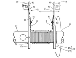
巻芯12を回転させるか否か、及び、一対のフライヤ31,31のいずれを回転させるかは、得ようとするコイルの仕様により異なる。例えば、図11に示すように、巻芯12を回転させずに、双方のフライヤ31を巻芯12の回転軸を回転中心として同時に逆方向に回転させると、双方のフライヤ31に設けられた蓄線具61からそれぞれ線材11が繰り出されて巻芯12に同時に巻回される。このとき、トラバース機構41により、一対のフライヤ31,31を巻芯12の軸方向に往復移動させれば、線材11を巻芯12に複数層に亘って整列巻きすることが可能となる。
これにより、一方のフライヤ31のみを順次回転させて、全ての線材11を巻芯12に巻回させる場合に比較して、その巻線に係る時間を短縮することができ、比較的短時間で巻始め端と巻終わり端が共に最外周層から導き出されたコイルを巻芯12の周囲に形成することが可能となる。
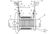
なお、双方のフライヤ31を同時に逆方向に回転させることに代えて、一方のフライヤ31を回転させた後、他方のフライヤ31を回転させることにより、巻芯12に線材11を巻回させることもできる。先ず、図12Aに示すように、巻芯12と他方のフライヤ31を回転させずに、一方のフライヤ31のみを巻芯12の軸を回転中心として回転させる。これにより、その一方のフライヤ31に設けられた蓄線具61から繰り出された線材11が巻芯12に巻回される。そして、一方のフライヤ31における蓄線具61の線材11が巻芯12に巻回された後にその一方のフライヤ31の回転を停止させる。その後、図12Bに示すように、他方のフライヤ31を巻芯12の軸を回転中心として回転させる。これにより、その他方のフライヤ31に設けられた蓄線具61から繰り出された線材11が、先に巻回された線材11の上に更に巻回される。
このように、一対のフライヤ31を別々に回転可能とすることにより、巻芯12に対して線材11を巻回させる仕様を多様化することができる。従って、巻始め端と巻終わり端が共に最外周層から導き出された複数種類のコイルを巻芯12の周囲に容易に形成することが可能となる。
また、上記巻線装置10は、巻芯12を回転させる巻芯回転手段としての巻芯用サーボモータ16を備えている(図1)。従って、フライヤ31の回転と同時に巻芯12も同一方向に同一の速度で回転させた場合、フライヤ31と巻芯12の相対的な位置関係が変化することは無い。
この場合、巻芯12と一緒に回転するフライヤ31の蓄線具61から線材11が巻芯12に巻回されることはなく、巻芯12と一緒に回転しないフライヤ31、例えば、停止状態のフライヤ31における蓄線具61から繰り出される線材11が、回転する巻芯12に巻回されることになる。
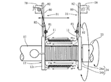
この巻回方法では、先ず、図13Aに示すように、巻芯用サーボモータ(巻芯回転手段)16により巻芯12を回転させるとともに、その巻芯12の回転と同時に一方のフライヤ31を巻芯12の回転と同一方向に同一の速度で回転させる。これにより、巻芯12と一緒に回転しないフライヤ31、例えば、停止状態のフライヤ31における蓄線具61から繰り出される線材11が巻芯12に巻回される。
他方のフライヤ31における蓄線具61の線材11が巻芯12に巻回された後に、その一方のフライヤ31の回転を停止させる。その後、図13Bに示すように、他方のフライヤ31を巻芯12の回転と同方向に同一の速度で回転させる。これにより、その一方のフライヤ31に設けられた蓄線具61から繰り出された線材11が、先に巻回された線材11の上に更に巻回される。
このように、巻芯12を回転させると共に、一対のフライヤ31を別々に回転させることにより、任意の巻数と任意の層数を有し、かつ巻始め端と巻終わり端が共に最外周層から導き出された複数種類のコイルを巻芯12の周囲に容易に形成することが可能となる。つまり、巻芯12に対して線材11を巻回させる仕様を更に多様化することが可能となる。
本実施形態に係る巻線装置10では、蓄線具61とともに、一対のフライヤ31,31にそれぞれテンション装置71を設けている。このため、巻芯12に線材11を所定のテンションで巻回することが可能となり、線材11の巻回作業においてテンションが異なることに起因する巻ムラが生じることを回避することができる。
本実施形態に係る巻線方法では、上述したように、巻線工程において蓄線具61を取付けたフライヤ31を回転させるので、その蓄線具61に線材11を蓄線させる蓄線工程が巻線工程の前に行われることになる。
本実施形態に係る巻線装置10では、蓄線具61が一対のフライヤ31に着脱自在に設けられている。このため、図10A及び図10Bに示すように、フライヤ31から離脱させた蓄線具61を用いて蓄線工程を行い、その後、蓄線具61をフライヤ31に取付ける蓄線具取付工程を行い、その更に後に、図11~図13Bに示すように、蓄線具61から繰り出される線材11を巻芯12に巻回する巻線工程を行うようにすれば、その巻線工程と同時に、別の蓄線具61を用いた蓄線工程を行うことが可能となる。
よって、本実施形態に係る巻線装置及び巻線方法では、複数の蓄線具61を準備することにより、巻線工程と蓄線工程を同時に行うことが可能となる。従って、蓄線工程を巻線工程と同時に行うことができずに、それらの工程を連続させることが必要な従来技術と比較して、速やかなコイルの製造が可能になる。
なお、上述した実施の形態では、巻芯12に線材11が直接巻回されて、いわゆる空芯コイルが形成される場合について説明したが、本発明はこれに限定されない。巻芯12に図示しないボビンを嵌着させて、そのボビンに線材11を巻回させてコイルを形成するようにしても良い。
また、上述した実施の形態では、蓄線具61をフライヤ31,31に着脱自在に取付ける機構が、蓄線具61に設けられたカップリング軸61dと、カップリング軸61dを取付けるロック機構64と、を有し、ロック機構64が設けられた取付軸63がフライヤ31に枢支される場合について説明したが、本発明はこれに限定されない。フライヤ31,31に蓄線具61を着脱自在に設けることができる限り、別の機構、例えば、ネジ止めにより蓄線具61をフライヤ31,31に着脱自在に取付けるようにしても良い。
以上のとおり、巻線装置10は、線材11が巻回される巻芯12と、その巻芯12を軸方向から挟むように配置された一対のフライヤ31と、一対のフライヤ31のいずれか一方又は双方を巻芯12の軸を回転中心として回転させるフライヤ回転手段(回転用サーボモータ51)と、一対のフライヤ31にそれぞれ着脱自在に設けられ巻芯12に巻回される線材11を蓄える蓄線具61と、一対のフライヤ31にそれぞれ設けられ蓄線具61から繰り出されて巻芯12に導かれる線材11にテンションを付与するテンション装置71と、を備える。
この構成では、巻芯12に巻回される線材11を蓄える蓄線具61を一対のフライヤ31にそれぞれ設けた。これにより、それらの蓄線具61に比較的長い線材11を蓄えさせて一対のフライヤ31を巻芯12に対して回転させることにより、比較的長い線材11を巻芯12の周囲に巻回させることが可能となり、巻数が比較的多い大型のコイルの製造が可能となる。
巻線装置10は、一対のフライヤ31のいずれか一方又は双方を巻芯12に対して軸方向に移動させるトラバース機構41を備えることが好ましい。また、巻線装置10は、巻芯12を軸回りで回転させる巻芯回転手段(巻芯用サーボモータ16)を備えることもでき、この場合、巻芯12は基端側が支持され、巻芯12の先端側を支持する支持具21を備えることが好ましい。トラバース機構41や巻芯回転手段(巻芯用サーボモータ16)を備えることにより、線材11の整列巻等も可能となり、巻線の多様性を図ることができる。
上記巻線装置10を用いた巻線方法は、必要な長さの線材11を両側から一対の蓄線具61に巻きつける蓄線工程と、線材11が両端から巻回された一対の蓄線具61を巻線装置10の一対のフライヤ31に取付ける蓄線具取付工程と、一対のフライヤ31のいずれか一方又は双方を巻芯12の軸を回転中心として回転させて蓄線具61から繰り出される線材11を巻芯12に巻回し、巻始め端と巻終わり端が共に最外周層から導き出されたコイルを巻芯12の周囲に形成する巻線工程と、を備える。この方法では、上記巻線装置10を用いるため、巻数が比較的多い大型のコイルを製造することができる。
蓄線具61として比較的長い線材11を蓄えることが可能なものを用いた場合、その蓄線具61に比較的長い線材11を蓄線させる蓄線工程は、実際に巻芯12に線材11を巻回する巻線工程以前に行われることになる。
巻線装置10は、蓄線具61が一対のフライヤ31に着脱自在に設けられている。このため、フライヤ31から離脱させた蓄線具61を用いて蓄線工程を行い、その後、蓄線具61をフライヤ31に取付ける蓄線具取付工程を行い、その更に後に、蓄線具61から繰り出される線材11を巻芯12に巻回する巻線工程を行うようにすれば、その巻線工程と同時に、別の蓄線具61を用いた蓄線工程を行うことが可能となる。
よって、上記巻線装置10及び巻線方法では、複数の蓄線具61を準備して、巻線工程と蓄線工程を同時に行うことにより、蓄線工程を巻線工程とを同時に行うことができずに、それらの工程を連続させることが必要な従来技術と比較して、速やかなコイルの製造が可能になる。
以上のとおり、上記構成によれば、巻数が比較的多い大型のコイルを製造し得る巻線装置10及びそれを用いた巻線方法を提供することができる。また、比較的長い線材11を巻回してコイルを製造する場合であっても、コイルを迅速に製造し得る巻線装置10及びそれを用いた巻線方法を提供することができる。つまり、巻数が比較的多い大型のコイルを迅速に製造し得る巻線装置10及びそれを用いた巻線方法を提供することができる。
以上、本発明の実施形態について説明したが、上記実施形態は本発明の適用例の一部を示したに過ぎず、本発明の技術的範囲を上記実施形態の具体的構成に限定する趣旨ではない。
本願は2018年6月25日に日本国特許庁に出願された特願2018-119519に基づく優先権を主張し、この出願の全ての内容は参照により本明細書に組み込まれる。
Claims (5)
- 線材が巻回される巻芯と、
前記巻芯を軸方向から挟むように配置された一対のフライヤと、
前記一対のフライヤのいずれか一方又は双方を回転させるフライヤ回転手段と、
前記一対のフライヤにそれぞれ着脱自在に設けられ前記巻芯に巻回される前記線材を蓄える蓄線具と、
前記一対のフライヤにそれぞれ設けられ前記蓄線具から繰り出されて前記巻芯に導かれる前記線材にテンションを付与するテンション装置と、
を備える巻線装置。 - 請求項1に記載の巻線装置であって、
前記一対のフライヤのいずれか一方又は双方を前記巻芯に対して軸方向に移動させるトラバース機構を備えた巻線装置。 - 請求項1に記載の巻線装置であって、
前記巻芯を軸回りで回転させる巻芯回転手段を備えた巻線装置。 - 請求項3に記載の巻線装置であって、
前記巻芯は基端側が支持され、前記巻芯の先端側を支持する支持具を備えた巻線装置。 - 請求項1に記載の巻線装置を用いた巻線方法であって、
必要な長さの線材を両側から一対の前記蓄線具に巻きつける蓄線工程と、
前記線材が両端から巻回された一対の前記蓄線具を前記巻線装置の前記一対のフライヤに取付ける蓄線具取付工程と、
前記一対のフライヤのいずれか一方又は双方を前記巻芯の軸を回転中心として回転させて前記蓄線具から繰り出される前記線材を前記巻芯に巻回し、巻始め端と巻終わり端が共に最外周層から導き出されたコイルを前記巻芯の周囲に形成する巻線工程と、
を備える巻線方法。
Priority Applications (3)
| Application Number | Priority Date | Filing Date | Title |
|---|---|---|---|
| US16/646,000 US11239029B2 (en) | 2018-06-25 | 2019-05-10 | Winding apparatus and winding method using same |
| CN201980003874.3A CN111052278B (zh) | 2018-06-25 | 2019-05-10 | 绕线装置以及使用该绕线装置的绕线方法 |
| EP19825366.8A EP3657520B1 (en) | 2018-06-25 | 2019-05-10 | Wire winding device and wire winding method using same |
Applications Claiming Priority (2)
| Application Number | Priority Date | Filing Date | Title |
|---|---|---|---|
| JP2018119519A JP7083705B2 (ja) | 2018-06-25 | 2018-06-25 | 巻線装置及びそれを用いた巻線方法 |
| JP2018-119519 | 2018-06-25 |
Publications (1)
| Publication Number | Publication Date |
|---|---|
| WO2020003766A1 true WO2020003766A1 (ja) | 2020-01-02 |
Family
ID=68984757
Family Applications (1)
| Application Number | Title | Priority Date | Filing Date |
|---|---|---|---|
| PCT/JP2019/018807 Ceased WO2020003766A1 (ja) | 2018-06-25 | 2019-05-10 | 巻線装置及びそれを用いた巻線方法 |
Country Status (5)
| Country | Link |
|---|---|
| US (1) | US11239029B2 (ja) |
| EP (1) | EP3657520B1 (ja) |
| JP (1) | JP7083705B2 (ja) |
| CN (1) | CN111052278B (ja) |
| WO (1) | WO2020003766A1 (ja) |
Families Citing this family (7)
| Publication number | Priority date | Publication date | Assignee | Title |
|---|---|---|---|---|
| CN111354567B (zh) * | 2020-04-22 | 2021-11-09 | 东莞市纵易智能装备有限公司 | 自动穿套管绕线机 |
| JP7476001B2 (ja) * | 2020-07-09 | 2024-04-30 | Nittoku株式会社 | 巻線装置及び巻線方法 |
| CN113942886B (zh) * | 2020-07-16 | 2023-05-02 | Ykk株式会社 | 线状体供给装置 |
| CN111681870B (zh) * | 2020-07-28 | 2025-09-02 | 珠海市恒诺科技有限公司 | 一种断线机构 |
| CN112372999B (zh) * | 2020-12-01 | 2025-06-27 | 威海鸿通管材股份有限公司 | 一种低温管螺旋缠绕设备及成型工艺 |
| CN113035566B (zh) * | 2021-02-24 | 2022-07-08 | 西南交通大学 | 电磁搅拌器线圈绕制装置 |
| BR102022008319A2 (pt) * | 2022-04-29 | 2023-11-14 | Krah Indústria E Comércio De Componentes Eletrônicos Ltda | Processo de fabricação de indutores e transformadores com bobinamento contínuo |
Citations (3)
| Publication number | Priority date | Publication date | Assignee | Title |
|---|---|---|---|---|
| JP2009252968A (ja) * | 2008-04-04 | 2009-10-29 | Toyota Motor Corp | 巻線装置 |
| JP2012146890A (ja) * | 2011-01-14 | 2012-08-02 | Nittoku Eng Co Ltd | コイル巻線装置及びコイル巻線方法 |
| JP2018119519A (ja) | 2017-01-27 | 2018-08-02 | マツダ株式会社 | エンジンの排気浄化装置 |
Family Cites Families (16)
| Publication number | Priority date | Publication date | Assignee | Title |
|---|---|---|---|---|
| US4262853A (en) * | 1974-03-19 | 1981-04-21 | Possis Corporation | Apparatus for winding armatures |
| US5794884A (en) * | 1992-09-23 | 1998-08-18 | Globe Products Inc. | Stator winding apparatus with selectively movable coil former |
| JPH06301914A (ja) * | 1993-04-14 | 1994-10-28 | Canon Inc | 磁気ヘッド用コイルの巻回方法および磁気ヘッド |
| JPH10154626A (ja) | 1996-11-25 | 1998-06-09 | Tdk Corp | 2層コイルの製造方法及び装置 |
| US6419181B1 (en) * | 1998-12-15 | 2002-07-16 | Axis Usa, Inc. | Flyer winders for dynamo-electric machine components |
| KR100459939B1 (ko) * | 2002-07-08 | 2004-12-03 | 에스케이 텔레콤주식회사 | 회의통화 기능을 위한 셀룰러 통신 시스템 |
| JP4321054B2 (ja) | 2002-12-03 | 2009-08-26 | 株式会社安川電機 | 平角線二重巻きの巻線方法およびその装置 |
| US7419116B2 (en) * | 2004-04-26 | 2008-09-02 | Globe Motors, Inc. | Method and apparatus for winding field coils for dynamo-electric machines |
| WO2007138863A1 (ja) * | 2006-05-26 | 2007-12-06 | Nittoku Engineering Co., Ltd. | 巻線装置、テンション装置、及び巻線方法 |
| JP5108648B2 (ja) * | 2008-06-24 | 2012-12-26 | 日特エンジニアリング株式会社 | コイル巻線方法およびコイル巻線装置 |
| JP4827892B2 (ja) * | 2008-06-27 | 2011-11-30 | 本田技研工業株式会社 | 巻線装置 |
| CN103430259B (zh) * | 2011-03-18 | 2016-05-11 | Sht有限公司 | 自动卷线机、空芯线圈及其卷线方法 |
| JP6501379B2 (ja) * | 2013-12-27 | 2019-04-17 | 日特エンジニアリング株式会社 | 巻線装置 |
| CN104538128B (zh) | 2014-12-09 | 2017-01-11 | 恩平市新概念音响科技有限公司 | 一种音频线绕线机构 |
| JP6436569B2 (ja) * | 2015-01-19 | 2018-12-12 | 日特エンジニアリング株式会社 | コイル製造装置 |
| CN108010716B (zh) * | 2017-01-03 | 2020-03-10 | 东莞理工学院 | 一种方便插线的电感绕线机 |
-
2018
- 2018-06-25 JP JP2018119519A patent/JP7083705B2/ja active Active
-
2019
- 2019-05-10 US US16/646,000 patent/US11239029B2/en active Active
- 2019-05-10 WO PCT/JP2019/018807 patent/WO2020003766A1/ja not_active Ceased
- 2019-05-10 CN CN201980003874.3A patent/CN111052278B/zh active Active
- 2019-05-10 EP EP19825366.8A patent/EP3657520B1/en active Active
Patent Citations (3)
| Publication number | Priority date | Publication date | Assignee | Title |
|---|---|---|---|---|
| JP2009252968A (ja) * | 2008-04-04 | 2009-10-29 | Toyota Motor Corp | 巻線装置 |
| JP2012146890A (ja) * | 2011-01-14 | 2012-08-02 | Nittoku Eng Co Ltd | コイル巻線装置及びコイル巻線方法 |
| JP2018119519A (ja) | 2017-01-27 | 2018-08-02 | マツダ株式会社 | エンジンの排気浄化装置 |
Non-Patent Citations (1)
| Title |
|---|
| See also references of EP3657520A4 |
Also Published As
| Publication number | Publication date |
|---|---|
| CN111052278A (zh) | 2020-04-21 |
| EP3657520A1 (en) | 2020-05-27 |
| EP3657520A4 (en) | 2021-04-21 |
| EP3657520B1 (en) | 2023-05-10 |
| JP7083705B2 (ja) | 2022-06-13 |
| US20200211768A1 (en) | 2020-07-02 |
| US11239029B2 (en) | 2022-02-01 |
| JP2020004750A (ja) | 2020-01-09 |
| CN111052278B (zh) | 2022-08-23 |
Similar Documents
| Publication | Publication Date | Title |
|---|---|---|
| JP7083705B2 (ja) | 巻線装置及びそれを用いた巻線方法 | |
| TWI598282B (zh) | Winding device and wire pairs of terminals bundling method | |
| CN101378212B (zh) | 绕线装置 | |
| US8250733B2 (en) | Automatic winder for an inside brushless stator | |
| JP6460865B2 (ja) | コイル巻線装置及びコイル製造方法 | |
| EP2682961B1 (en) | Wire winding apparatus and wire winding method | |
| JP6436569B2 (ja) | コイル製造装置 | |
| KR101665281B1 (ko) | 코일 제조 장치 | |
| JP6315792B2 (ja) | コイル製造装置 | |
| CN101454850A (zh) | 绕线装置、张紧装置以及绕线方法 | |
| CN113785371B (zh) | 绕线机和绕线方法 | |
| JP2003169455A (ja) | ノズル保持具、ノズル回動ユニット、巻線機及び巻線方法 | |
| CN100467363C (zh) | 一种绕线机 | |
| JP2017164873A (ja) | ワイヤ加工システム及びワイヤ加工方法 | |
| JPH06251972A (ja) | コイルの巻線方法および巻線装置 | |
| CN111788648A (zh) | 绕线装置、使用该绕线装置的制造设备、绕线方法、以及完成品的制造方法 | |
| WO2020039884A1 (ja) | 巻線装置及び巻線方法 | |
| JP2006340543A (ja) | 巻線装置及び巻線方法 |
Legal Events
| Date | Code | Title | Description |
|---|---|---|---|
| 121 | Ep: the epo has been informed by wipo that ep was designated in this application |
Ref document number: 19825366 Country of ref document: EP Kind code of ref document: A1 |
|
| ENP | Entry into the national phase |
Ref document number: 2019825366 Country of ref document: EP Effective date: 20200219 |
|
| NENP | Non-entry into the national phase |
Ref country code: DE |