WO2020003766A1 - Dispositif d'enroulement de fil et procédé d'enroulement l'utilisant - Google Patents
Dispositif d'enroulement de fil et procédé d'enroulement l'utilisant Download PDFInfo
- Publication number
- WO2020003766A1 WO2020003766A1 PCT/JP2019/018807 JP2019018807W WO2020003766A1 WO 2020003766 A1 WO2020003766 A1 WO 2020003766A1 JP 2019018807 W JP2019018807 W JP 2019018807W WO 2020003766 A1 WO2020003766 A1 WO 2020003766A1
- Authority
- WO
- WIPO (PCT)
- Prior art keywords
- wire
- core
- winding
- pair
- flyers
- Prior art date
- Legal status (The legal status is an assumption and is not a legal conclusion. Google has not performed a legal analysis and makes no representation as to the accuracy of the status listed.)
- Ceased
Links
Images






Classifications
-
- H—ELECTRICITY
- H01—ELECTRIC ELEMENTS
- H01F—MAGNETS; INDUCTANCES; TRANSFORMERS; SELECTION OF MATERIALS FOR THEIR MAGNETIC PROPERTIES
- H01F41/00—Apparatus or processes specially adapted for manufacturing or assembling magnets, inductances or transformers; Apparatus or processes specially adapted for manufacturing materials characterised by their magnetic properties
- H01F41/02—Apparatus or processes specially adapted for manufacturing or assembling magnets, inductances or transformers; Apparatus or processes specially adapted for manufacturing materials characterised by their magnetic properties for manufacturing cores, coils, or magnets
- H01F41/04—Apparatus or processes specially adapted for manufacturing or assembling magnets, inductances or transformers; Apparatus or processes specially adapted for manufacturing materials characterised by their magnetic properties for manufacturing cores, coils, or magnets for manufacturing coils
- H01F41/06—Coil winding
- H01F41/082—Devices for guiding or positioning the winding material on the former
- H01F41/088—Devices for guiding or positioning the winding material on the former using revolving flyers
-
- H—ELECTRICITY
- H01—ELECTRIC ELEMENTS
- H01F—MAGNETS; INDUCTANCES; TRANSFORMERS; SELECTION OF MATERIALS FOR THEIR MAGNETIC PROPERTIES
- H01F41/00—Apparatus or processes specially adapted for manufacturing or assembling magnets, inductances or transformers; Apparatus or processes specially adapted for manufacturing materials characterised by their magnetic properties
- H01F41/02—Apparatus or processes specially adapted for manufacturing or assembling magnets, inductances or transformers; Apparatus or processes specially adapted for manufacturing materials characterised by their magnetic properties for manufacturing cores, coils, or magnets
- H01F41/04—Apparatus or processes specially adapted for manufacturing or assembling magnets, inductances or transformers; Apparatus or processes specially adapted for manufacturing materials characterised by their magnetic properties for manufacturing cores, coils, or magnets for manufacturing coils
- H01F41/06—Coil winding
- H01F41/094—Tensioning or braking devices
-
- H—ELECTRICITY
- H01—ELECTRIC ELEMENTS
- H01F—MAGNETS; INDUCTANCES; TRANSFORMERS; SELECTION OF MATERIALS FOR THEIR MAGNETIC PROPERTIES
- H01F41/00—Apparatus or processes specially adapted for manufacturing or assembling magnets, inductances or transformers; Apparatus or processes specially adapted for manufacturing materials characterised by their magnetic properties
- H01F41/02—Apparatus or processes specially adapted for manufacturing or assembling magnets, inductances or transformers; Apparatus or processes specially adapted for manufacturing materials characterised by their magnetic properties for manufacturing cores, coils, or magnets
- H01F41/04—Apparatus or processes specially adapted for manufacturing or assembling magnets, inductances or transformers; Apparatus or processes specially adapted for manufacturing materials characterised by their magnetic properties for manufacturing cores, coils, or magnets for manufacturing coils
- H01F41/06—Coil winding
- H01F41/096—Dispensing or feeding devices
Definitions
- the present invention relates to a winding device and a winding method using the same, so that the winding start end and the winding end end of the coil are both located on the outermost layer of the coil.
- a double-row spiral coil having first and second coils in which a wire is spirally wound and an inner crossover wire connecting inner peripheral ends of the first and second coils is known.
- a manufacturing apparatus of such a double-row spiral coil a first and a second wheel which are opposed to each other with a gap of two wires and rotate around the winding core in mutually opposite directions, A wire feeder that feeds the wire toward the guide groove or hole of the wheel, and a wire storage unit that stores the wire in a wound state and feeds the wire toward the guide groove or hole of the second wheel.
- An apparatus has been proposed (see paragraphs “0010”, “0011”, and “0019” of JPH10-154626A).
- the wire supplied from the wire supply unit is stored in the storage unit, and thereafter, an arbitrary position of the wire between the wire supply unit and the storage unit is started to be wound,
- the first and second wheels are rotated in opposite directions.
- the wire rods extending on both sides from the start position of the winding are simultaneously wound around the core in opposite directions, and a winding portion having two layers in the axial direction of the core is formed on the outer periphery of the core. be able to.
- the winding start end and the winding end of the wire are compared with the double-row spiral coil drawn from the same outermost winding layer. It can be easily manufactured.
- the wire supplied from the wire supply unit is stored in the wire storage unit, and then the first and second wheels are rotated in opposite directions to each other, so that both of them are provided. Is wound around the core. For this reason, the size of the obtained coil is limited to the length of the wire that can be supplied from the wire storage unit, and it is difficult to manufacture a relatively large coil using a relatively long wire.
- the coil that can be manufactured by the coil manufacturing apparatus in JPH10-154626A is a relatively small coil such as a double-row spiral coil in which first and second coils having the same number of turns are connected by an inner crossover. There is a problem that is limited to.
- An object of the present invention is to provide a winding device and a winding method using the same, which can rapidly manufacture a large coil having a relatively large number of turns.
- a winding device wherein a core around which a wire is wound, a pair of flyers arranged to sandwich the core from an axial direction, and any of the pair of flyers Flyer rotating means for rotating one or both of them, a wire storage device detachably provided on the pair of flyers and storing the wire wound around the core, and a storage device provided on the pair of flyers, respectively.
- a tension device that applies tension to the wire rod fed out from the wire and guided to the core.
- a winding method using the winding device wherein a wire storing step of winding a wire having a required length around the pair of the wire storing tools from both sides, A wire storage tool mounting step of mounting the pair of wire storage devices wound from both ends to the pair of flyers of the winding device, and rotating one or both of the pair of flyers around the axis of the winding core; A winding step of winding the wire rod fed out of the wire accumulating device around the winding core so as to form a coil around which the winding start end and the winding end end are led out from the outermost layer. And.
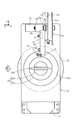
- FIG. 1 is a front view showing a winding device according to an embodiment of the present invention.
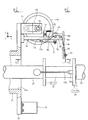
- FIG. 2 is a sectional view taken along line II-II of FIG.
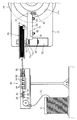
- FIG. 3 is a view of the flyer as viewed from the direction III in FIG.
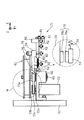
- FIG. 4 is a sectional view taken along line IV-IV of FIG.
- FIG. 5 is a sectional view taken along line VV of FIG.
- FIG. 6 is an enlarged cross-sectional view of a portion VI in FIG.
- FIG. 7 is an enlarged perspective view of the wire storage tool.
- FIG. 8 is an enlarged sectional view of a portion VIII in FIG. 4, showing a mechanism for detachably attaching the wire storage tool to the flyer.
- FIG. 1 is a front view showing a winding device according to an embodiment of the present invention.
- FIG. 2 is a sectional view taken along line II-II of FIG.
- FIG. 3 is a view of the flyer as viewed from the direction III in FIG
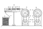
- FIG. 9 is a diagram illustrating a state in which a wire is wound around a wire storage tool attached to a flyer.
- FIG. 10A is a diagram showing a state in which a wire is wound around one of a pair of wire storage tools removed from a flyer.
- FIG. 10B is a diagram illustrating a state in which the wire is wound around the other of the pair of wire storage tools removed from the flyer.
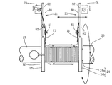
- FIG. 11 is a conceptual diagram showing a state in which a pair of flyers are rotated in opposite directions to simultaneously wind the wire fed from both wire storage tools around the core.
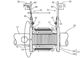
- FIG. 12A is a conceptual diagram showing a state in which a wire fed from a wire storage tool of one flyer is wound around a core.
- FIG. 12B is a conceptual diagram showing a state in which a wire fed from a wire storage tool of one flyer is wound around a core, and then a wire fed from a wire storage tool of the other flyer is wound around a core.
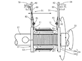
- FIG. 13A is a conceptual diagram showing a state in which the core and one flyer are simultaneously rotated to wind the wire fed from the wire accumulator of the other flyer around the core.
- FIG. 13B shows that the core and one flyer are simultaneously rotated to wind the wire fed from the wire accumulator of the other flyer around the core, and then the other flyer is rotated together with the core to stop the rotation.
- It is a conceptual diagram which shows a mode that the wire unwound from the wire storage tool of one flyer is wound around a core.
- FIG. 1 shows a winding device 10 according to an embodiment of the present invention.
- three axes of X, Y, and Z orthogonal to each other are set.
- the X-axis extends in a substantially horizontal front-rear direction
- the Y-axis extends in a substantially horizontal lateral direction
- the Z-axis extends in a substantially vertical direction.
- the winding device 10 includes a winding core 12 around which a wire 11 is wound, and a winding core servomotor 16 serving as a winding core rotating unit that rotates the winding core 12 around an axis.
- the core 12 has a cylindrical main body 12b having a circular cross section, and a flange 12c provided on the base end side of the main body 12b.
- the flange 12c has a larger diameter than the main body 12b.
- An extension shaft 17 is coaxially provided on a rotation shaft 16a of the core servomotor 16 via a joint 16b.
- a base end of the winding core 12 on the flange 12c side is coaxially provided at a distal end of the extension shaft 17.
- the winding core servomotor 16 is attached to the base 9 via a pedestal 16 c with its rotating shaft 16 a directed in the X-axis direction. Therefore, when the core servomotor 16 is driven, the core 12 in which the base end is attached to the rotation shaft 16a of the core servomotor 16 via the extension shaft 17 can rotate with the X axis as the rotation axis. is there.
- the winding device 10 includes a support 21 that supports the distal end of the core 12 whose base end is supported by the extension shaft 17.
- the support 21 includes a supporting servomotor 22, a pressing shaft 23 provided coaxially to a rotating shaft 22 a of the supporting servomotor 22 via a joint 22 b, and the supporting shaft 23 together with the supporting servomotor 22.
- the moving mechanism 25 in this embodiment includes a guide rail 27 disposed on the base 9 in parallel with the rotation axis (X axis) of the core 12, a moving body 26 guided by the guide rail 27,
- the motor 9 includes a movement motor 28 provided on the table 9 and a ball screw 29 connected to a rotation shaft 28 a of the movement motor 28.
- the moving motor 28 is provided such that its rotating shaft 28 a is parallel to the guide rail 27.
- the ball screw 29 extends in the rotation axis direction (X-axis direction) of the core 12 and is screwed to the moving body 26.
- the supporting servomotor 22 is attached to the moving body 26 via the pedestal 22c such that the holding shaft 23 is oriented in the X-axis direction and the tip of the holding shaft 23 faces the tip of the core 12.
- the moving mechanism 25 when the moving motor 28 is driven, the ball screw 29 rotates, and the moving body 26 screwed to the ball screw 29 is guided by the guide rail 27 and moves. Then, the supporting servomotor 22 mounted on the moving body 26 also moves in the rotation axis direction (X-axis direction) of the core 12 together with the moving body 26.
- the holding shaft 23 provided on the supporting servomotor 22 so as to be coaxial with the core 12 is formed. It approaches the core 12.
- the holding member 24 provided at the tip of the holding shaft 23 is configured to be able to contact the tip of the core 12 (FIG. 3).
- a hole 23a is formed at the tip of the holding shaft 23 in the axial direction from the tip edge.
- the holding member 24 has an insertion portion 24 a inserted into the hole 23 a and a holding portion 24 b formed to have a larger diameter than the holding shaft 23 and to actually contact the tip of the core 12.
- a long hole 23b extending in the axial direction is formed at the distal end of the pressing shaft 23 in the peripheral wall thereof. The long hole 23b is formed to penetrate from the outer periphery of the holding shaft 23 to the inner periphery of the hole 23a.
- the coil spring 23c is inserted into the hole 23a.
- An insertion portion 24a is further inserted into the hole 23a so as to compress the coil spring 23c.
- a male screw 23d is inserted into the elongated hole 23b, and is screwed to the insertion portion 24a of the holding member 24.
- the holding member 24 is provided at the tip of the holding shaft 23 so as to be movable in the axial direction within the moving range of the male screw 23d in the long hole 23b.
- the coil spring 23c urges the retainer 24 in a direction to protrude from the hole 23a by a force to be extended.
- the male screw 23d contacts the hole edge of the long hole 23b to prevent the insertion portion 24a of the holding member 24 from coming off the hole 23a.
- a slit 12 a extending in the axial direction from the tip is formed so as to extend through the core 12 and extend to the extension shaft 17.
- the pressing portion 24b is formed with a ridge 24c that prohibits the slit 12a from entering the slit 12a and reducing the width of the slit 12a. Then, when the holding shaft 23 approaches the core 12 and the holding member 24 provided at the tip of the holding shaft 23 comes into contact with the tip of the core 12, as shown in FIG. It is prohibited to enter the slit 12a and narrow the width of the slit 12a.
- the pressing portion 24b is in contact with the leading end of the core 12 to limit the winding width of the wire 11 in the core 12 that can be wound.
- the holding tool 24 supports the leading end of the core 12.
- the supporting servomotor 22 (FIG. 1) rotates the presser 24 in synchronization with the rotation of the core 12 so that the relative positional relationship between the core 12 and the presser 24 does not change.
- the moving mechanism 25 is configured such that the moving distance of the moving body 26 is longer than the winding width of the core 12, that is, the length of the main body 12b of the core 12.
- the winding device 10 includes a pair of flyers 31, 31 arranged so as to sandwich the winding core 12 from the axial direction.
- a sliding cylinder 32 is fitted into the extension shaft 17 having the base end of the core 12 attached to the distal end so as to be movable in the longitudinal direction with respect to the extension shaft 17.
- a sliding cylinder 32 is fitted into the holding shaft 23 that supports the tip of the core 12 so as to be movable in the longitudinal direction with respect to the holding shaft 23.
- a rotating cylinder 34 is fitted into the respective sliding cylinders 32 of the extension shaft 17 and the holding shaft 23 via a bearing 33.
- the flyers 31 are attached to the ends of the rotary cylinders 34 on the core 12 side, respectively.
- the pair of flyers 31 and 31 are attached to the rotating cylinder 34 fitted to the extension shaft 17 and the holding shaft 23 via the sliding cylinder 32.
- Each of the pair of flyers 31, 31 is provided so as to be rotatable around the rotation axis (X axis) of the core 12 and to be movable in the direction of the rotation axis.
- the winding device 10 of the present embodiment having such a pair of flyers 31, 31 synchronizes or separates one or both of the pair of flyers 31, 31 around the axis of the core 12 as a rotation center.
- the apparatus includes a pair of rotary servomotors 51 constituting a flyer rotating means for rotating, and a traverse mechanism 41 for moving one or both of the pair of flyers 31, 31 in the axial direction with respect to the core 12.
- the traverse mechanism 41 is configured so that the pair of flyers 31, 31 can be moved separately.
- the traverse mechanism 41 includes a plurality of support walls 43 that pivotally support the pair of rotary cylinders 34 via bearings 42, a pair of movable tables 44 on which the plurality of support walls 43 are erected, and a rotating shaft of the core 12.
- a pair of guide rails 45 arranged on the base 9 so as to be parallel to the moving table 44
- a pair of traverse motors 46 provided on the base 9, and a rotation shaft 46a of the traverse motor 46.
- a pair of ball screws 47 A pair of ball screws 47.
- the traverse motor 46 is provided such that its rotating shaft 46a is parallel to the guide rail 45.
- the ball screw 47 extends in the rotation axis direction (X-axis direction) of the core 12 and is screwed to the movable base 44.
- the traverse mechanism 41 In the traverse mechanism 41, when the traverse motor 46 is driven, the ball screw 47 is rotated, and the movable base 44 screwed to the ball screw 47 is guided and moved by the guide rail 45. Then, the support wall 43 erected on the movable base 44 also moves in the same direction, and the rotary cylinder 34 pivotally supported by the support wall 43 moves in the axial direction (X-axis direction) of the core 12 together with the flyer 31. .
- the traverse mechanism 41 since the traverse motor 46 and the like are provided for each of the pair of flyers 31, 31, the pair of flyers 31, 31 can be moved separately.
- the traverse mechanism 41 can also move the pair of flyers 31, 31 at the same time.
- the winding device 10 includes the pair of rotation servomotors 51 that can separately rotate the pair of flyers 31, 31 as the flyer rotating unit that rotates the pair of flyers 31, 31.
- the pair of rotation servomotors 51 are provided on the respective moving tables 44 adjacent to the respective rotating cylinders 34.
- a drive pulley 52 is provided on the rotation shaft 51 a of the rotation servomotor 51, and a driven pulley 53 is provided at a position corresponding to the drive pulley 52 in the rotary cylinder 34.
- a belt 54 is provided between the drive pulley 52 of the rotation servomotor 51 and the pulley 53 of the rotary cylinder 34.
- the rotation servomotor 51 which is a flyer rotation means
- the rotation shaft 51a together with the driving pulley 52
- the rotation is transmitted to the rotation cylinder 34 via the belt 54 and the driven pulley 53
- the rotation cylinder 34 rotates. I do.
- the rotating cylinder 34 rotates, the flyer 31 provided on the rotating cylinder 34 rotates around the core 12 as a rotation center.
- the rotation servomotor 51 is provided for each of the pair of flyers 31, 31, the pair of flyers 31, 31 can be separately rotated.
- the pair of rotary servomotors 51 can also rotate the pair of flyers 31, 31 in synchronization.
- the pair of flyers 31, 31 are provided on the pair of rotating cylinders 34 on the sides facing each other.
- the flyers 31, 31 provided on the pair of rotary cylinders 34, respectively, are rectangular plate members along a plane orthogonal to the rotation axis of the core 12, and the extension shaft 17 or the holding shaft 23 can be inserted into the center thereof.
- a round hole 31a is formed.
- a wire storing tool 61 for storing the wire 11 wound around the core 12 and the wire storing tool 61 is fed from the wire storing tool 61.
- a tension device 71 for applying tension to the wire 11 guided to the winding core 12.
- a control unit 77 having a central processing unit built in a hard case is attached to the other end in the long side direction of the pair of fryers 31 having a rectangular shape, as a feeding speed control means described later.
- the wire storage tool 61 provided on one of the pair of fryers 31, 31 and the wire storage tool 61 provided on the other have the same structure. Further, the tension device 71 provided on one of the pair of flyers 31 and 31 has the same structure as the tension device 71 provided on the other. For this reason, the storage wire 61 and the tension device 71 provided in the flyer 31 in which the extension shaft 17 is inserted into the round hole 31a among the pair of flyers 31 and 31 will be described as a representative, and the holding shaft 23 is inserted into the round hole 31a. The description of the wire accumulator 61 and the tension device 71 provided in the flyer 31 through which is inserted is omitted.
- the wire storage tool 61 includes a bottomed tubular winding material 61a around which the wire 11 is actually wound, and an axial direction around the winding material 61a.
- This is a plastic spool having a pair of flange portions 61b and 61c formed apart from each other.
- the wire accumulator 61 has a relatively large diameter so that a relatively long wire 11 can be wound.
- a coupling shaft 61d is formed on the wire storage tool 61 so as to protrude on the central axis thereof.
- An annular groove 61e is formed at the tip of the coupling shaft 61d in the circumferential direction.
- a pivot support 62 is provided on the outer peripheral portion of the flyer 31 in parallel with the core 12, and the pivot support 62 is provided in the rotational tangential direction of the flyer 31.
- An extending mounting shaft 63 is pivotally supported.
- a lock mechanism 64 (FIG. 8) is provided at the tip of the mounting shaft 63.
- the lock mechanism 64 in this embodiment includes a cylindrical body 64a having a coupling hole 64b into which the coupling shaft 61d of the wire storage tool 61 can be inserted, and a cup provided in the cylindrical body 64a.
- a lock member 64c that engages with the annular groove 61e formed on the ring shaft 61d, a spring 64d that presses the lock member 64c against the annular groove 61e, and the like are provided.
- the cylindrical body 64 a is provided coaxially at the tip of the mounting shaft 63.
- a slit 64e extending in the axial direction from the end of the cylindrical body 64a is formed.
- the coupling shaft 61d is formed with a projection 61k that can enter the slit 64e. For this reason, when the coupling shaft 61d is inserted into the coupling hole 64b against the urging force of the spring 64d, the locking member 64c is pressed against the annular groove 61e by the urging force of the spring 64d, so that the coupling shaft 61d. From the coupling hole 64b.
- the wire storage tool 61 is detachably attached to the attachment shaft 63 via the lock mechanism 64.
- the wire storage tool 61 rotates together with the mounting shaft 63 while being mounted on the mounting shaft 63, and is prohibited from rotating independently of the mounting shaft 63.
- a feeding motor 72 capable of controlling the rotation speed of the mounting shaft 63 is mounted on the pivot support 62 such that the rotating shaft 72 a is parallel to the mounting shaft 63.
- a driven pulley 73a is provided on the mounting shaft 63 on which the lock mechanism 64 is provided, and a driving pulley 73b is provided on the rotating shaft 72a of the feeding motor 72.
- a belt 73c is provided between the driven pulley 73a and the driving pulley 73b.
- the tension device 71 includes the above-described feeding motor 72, a tension bar 74 having a turning pulley 74 a as a wire guide provided at a distal end and a base end pivotally supported, and a tension bar 74.
- Coil spring 75 which is an elastic member that generates an elastic force corresponding to the rotation angle of the motor
- linear sensor 76 which is a detecting means for detecting the rotation angle of tension bar 74
- a control unit 77 (FIG. 3) which is a feeding speed control means for controlling the feeding speed of the wire 11 so that the angle becomes a predetermined angle.
- a mounting base 78 is provided on the outer periphery of the flyer 31 in the vicinity of the pivot support 62 and adjacent to the feed motor 72.
- the mounting base 78 is erected on the outer periphery of the flyer 31 so as to be parallel to the pivot base 62.
- a base end of a tension bar 74 is pivotally supported at an intermediate portion of the mounting base 78.
- the tension bar 74 is pivotally supported so as to cross the mount 78.
- a turning pulley 74a serving as a wire guide is pivotally supported.
- a plurality of pulleys 79 around which the wire material 11 unwound from the wire storage tool 61 is wound are pivotally supported on the tip side of the mounting base 78 beyond the tension bar 74.
- the wire 11 is guided by the plurality of pulleys 79 toward the base end side of the mounting base 78, is wound around the turning pulley 74 a so as to be folded, and then returns to the distal end side of the mounting base 78 from the turning pulley 74 a.
- An extension piece 80 extending toward the core 12 is attached to the tip of the attachment base 78.
- An extension pulley 81 that guides the wire 11 to the core 12 is provided at an end of the extension piece 80 on the core 12 side.
- a plurality of guide pulleys 82 for feeding out the wire 11 folded by the deflecting pulley 74 a and guiding it to the pulley 81 are pivotally supported on the mounting base 78 and the extension piece 80.
- the coil spring 75 is an elastic member that urges the turning pulley 74 a toward the base end of the mounting base 78.
- One end of the coil spring 75 is attached to the proximal end side of the tension bar 74, and the other end is attached to the distal end side of the attachment base 78 via an attachment member 83.
- the coil spring 75 is provided along the mount 78.
- the fixed position of the other end of the coil spring 75 attached to the attachment base 78 via the attachment member 83 can be changed.
- the coil spring 75 generates an elastic force according to the rotation angle of the tension bar 74.
- the linear sensor 76 which is a detecting means for detecting the rotation angle of the tension bar 74, includes a sensor rod 76a and a sensor head 76b.
- the sensor rod 76a is attached to the tension bar 74 and moves with the rotation of the tension bar 74.
- the sensor head 76b is provided on the mounting base 78 and is configured to output a voltage based on the position of the sensor rod 76a.
- the linear sensor 76 is connected to a control unit (delivery speed control means) 77 (FIG. 3), and a signal detected by the linear sensor 76 is output to the control unit (delivery speed control means) 77.
- a control unit that maintains the balance with the storage device 61 and the tension device 71 is provided at the end of the flyer 31 on the opposite side to the side where the wire storage device 61 and the tension device 71 are provided.
- 77 is provided at the end of the flyer 31 on the opposite side to the side where the wire storage device 61 and the tension device 71 are provided.
- the control unit 77 has a hard case and a central processing unit built in the hard case.
- the central processing unit of the control unit 77 calculates the rotation angle of the tension bar 74 based on the detection signal of the linear sensor 76, and adjusts the rotation speed of the rotation shaft 72a of the delivery motor 72 so that the angle becomes a predetermined angle. Control.
- the central processing unit of the control unit 77 controls the rotation speed of the rotating shaft 72 a of the feeding motor 72 to adjust the rotation speed of the wire storage tool 61, and is released from the wire storage tool 61 to the core 12. It is configured such that the feeding speed of the wire 11 going forward is matched with the winding speed of the wire 11 around the core 12. As described above, the control unit 77 functions as a payout speed control unit that controls the payout speed of the wire 11 that is fed from the wire storage tool 61 toward the core 12.
- the coil spring 75 urges the tip of the mounting base 78 from which the wire 11 is fed toward the winding core 12 in a direction to separate the turning pulley 74a as a wire guide, and is wound around the turning pulley 74a.
- the wire 11 is stretched so that a predetermined tension is applied to the wire 11.
- the control unit 77 serving as the feeding speed control means includes a feeding speed (feeding amount) of the wire 11 that is unwound from the storage wire tool 61 serving as a supply source of the wire 11 and is fed toward the winding core 12,
- the rotation speed of the feeding motor 72 is controlled so that the winding speed (winding amount) of the wire 11 is balanced with that in the above, and the deflecting pulley 74 a around which the wire 11 is wound is urged by the coil spring 75.
- the tension bar 74 is configured to be held at a predetermined rotation angle.
- the spring force of the coil spring 75 acts on the wire 11 in accordance with the rotation angle of the tension bar 74, and a predetermined tension based on this spring force is applied. For this reason, in the winding operation of winding the wire 11 around the winding core 12, if the winding speed (winding amount) of the wire 11 around the winding core 12 changes, the rotation angle of the tension bar 74 changes, and the wire rod 11 changes. The tension applied to 11 fluctuates.
- the control unit (delivery speed control means) 77 receiving such feedback controls the rotation speed of the feeding motor 72 so that the rotation angle of the tension bar 74 returns to a predetermined angle, and controls the rotation speed of the wire storage tool 61. Is adjusted so that the feeding speed of the wire 11 released from the wire accumulating tool 61 toward the winding core 12 is matched with the winding speed on the winding core 12. Thereby, the rotation angle of the tension bar 74 returns to the predetermined angle, and the tension applied to the wire 11 returns to the predetermined value.
- the mounting position of the mounting member 83 on the mounting base 78 is changed. Accordingly, the length of the coil spring 75 when the tension bar 74 is at a predetermined rotation angle can be changed, and the spring force exerted on the tension bar 74 from the coil spring 75 can be adjusted. The desired tension can be obtained.
- a wire storage tool 61 for storing the wire rod 11 wound around the core 12 is provided in each of the pair of fryers 31.
- the winding method of the wire 11 using the winding device 10 includes a wire storing step of winding the wire 11 of a required length around a pair of wire storing tools 61 from both sides, and either one of the pair of flyers 31, 31 or
- the wire material 11 fed from the wire storage tool 61 is wound around the core 12 by rotating both of them synchronously or separately about the axis of the core 12 as the center of rotation, and the winding start end and the winding end are both from the outermost layer. Winding the formed coil around the winding core 12.
- the wire storage tool 61 is detachably provided on the pair of flyers 31, 31, respectively. For this reason, it is also possible to perform the above-described wire storing step in a state where the wire storing tool 61 is detached from the pair of fryers 31, 31.
- the wire storing step is performed using the wire storing tool 61 detached from the flyers 31, 31, a pair of the wire storing tools 61 in which the wire 11 is wound from both ends between the wire storing step and the winding step. Is attached to a pair of flyers 31 of the winding device 10.
- the wire 11 having a required length is wound around a pair of wire storing tools 61 from both sides. Prior to the work of winding the wire 11 around the wire storage tool 61, a pair of wire storage tools 61 and the wire 11 having a required length are prepared.
- the necessary length of the wire 11 is a wire 11 having a length necessary to form a single coil to be obtained.
- FIG. 9 shows a case where a calibrator 90 for removing a bending habit of the wire 11 unraveled from the drum 8 is used.
- the calibrating machine 90 includes a cutting machine 91 that cuts the wire 11, a wire gripper 92 that grips the wire 11, a plurality of vertical calibration rollers 93 for removing a vertical bending habit of the wire 11, And a plurality of lateral calibration rollers 94 for removing the lateral bending habit of the above.
- the wire 11 is wound around the wire accumulating tool 61 after the bending habit is removed by passing between the plurality of rollers 93 and 94 of the calibrator 90.
- the cutting machine 91 holds the wire 11 fed from the drum 8 by the wire holding machine 92. Cuts the wire 11. Then, as shown in FIG. 1, the cut end is fixed to the other wire storage tool 61 provided on the other flyer 31. After that, the feeding motor 72 attached to the flyer 31 provided with the other wire storage tool 61 is driven to rotate the other wire storage tool 61. At this time, in the feed-out motor 72 attached to the flyer 31 provided with the one storage device 61, the one storage device 61 is rotated in the opposite direction, and the other storage device 61 is rotated. Is unwound from the one wire storage tool 61 and fed out.
- the spool rotating machine 95 provided separately from the winding device 10 is used.
- the wire rod 11 is wound around the wire storage tool 61.
- the spool rotating machine 95 shown in the figure has a base plate 98 provided with a rotating body 96 to which the wire storage tool 61 is attached and a motor 97 for rotating the rotating body 96.
- a storage wire 61 is attached to the rotating body 96, and the end of the wire 11 unraveled from the drum 8 is fixed to the storage wire 61, and then the motor 97 is driven to rotate the storage wire 61.
- the wire 11 unwound from the drum 8 is wound around the wire 61.
- Two spool rotating machines 95 are used adjacent to each other.
- One of the spooling tools 61 is attached to a rotating body 96 of one spool rotating machine 95, and the other is attached to a rotating body 96 of the other spool rotating machine 95.
- the storage wire tool 61 is attached. After the wire 11 having a required length is wound around one of the wire accumulators 61, the wire 11 pulled out from the drum 8 is gripped by the wire gripper 92 of the calibrator 90, and the wire 11 is cut by the cutting machine 91. Disconnect.
- the spool rotating machine 95 and the calibrator 90 described above are an example of a device for winding the wire 11 around the wire storage device 61, and the device for winding the wire 11 around the wire storage device 61 is limited to this example. Not something.
- any device may be used as long as the wire 11 having a required length can be wound around the wire storing tool 61 detached from the pair of fryers 31, 31.
- the wire storing tool attaching step is a necessary step when the wire storing step is performed in a state where the wire storing tool 61 is detached from the pair of fryers 31, 31.
- a pair of wire storage devices 61 around which the wire 11 is wound from both ends are mounted on a pair of flyers 31 of the winding device 10.
- the wire storage tool 61 is provided with a coupling shaft 61d, and a lock mechanism 64 is provided at the tip of the mounting shaft 63 in the flyer 31.
- a lock mechanism 64 is provided at the tip of the mounting shaft 63 in the flyer 31.
- the lock member 64c When the coupling shaft 61d is inserted into the coupling hole 64b, the lock member 64c is pressed against the annular groove 61e by the urging force of the spring 64d. This prevents the coupling shaft 61d from coming out of the coupling hole 64b.
- the lock mechanism 64 is configured such that the projection 61k enters the slit 64e with the coupling shaft 61d inserted into the coupling hole 64b. Therefore, the wire storage tool 61 is non-rotatably mounted on the mounting shaft 63.
- Winding process> In the winding step, one or both of the pair of flyers 31 and 31 are rotated synchronously or separately about the center axis of the winding core 12 as a center of rotation, and the wire 11 fed from the wire storage tool 61 is wound into the winding core 12. And a coil whose winding start end and winding end are both drawn out of the outermost layer is formed around the winding core 12.
- the wire storage tools 61 for storing the wire 11 wound around the winding core 12 are provided on the pair of fryers 31 respectively. Therefore, the relatively long wire 11 is wound around the core 12 by storing the relatively long wire 11 in the wire accumulating tool 61 and rotating the pair of flyers 31 with respect to the core 12. And a relatively large coil can be manufactured. Therefore, according to the present embodiment, it is possible to provide a winding device 10 capable of manufacturing a large-sized coil having a relatively large number of turns, and a winding method using the same.
- ⁇ Whether or not to rotate the core 12 and which of the pair of flyers 31 and 31 to rotate depends on the specification of the coil to be obtained. For example, as shown in FIG. 11, when both flyers 31 are simultaneously rotated in the opposite directions about the rotation axis of the core 12 without rotating the core 12, the accumulators provided on both the flyers 31 are rotated. The wires 11 are respectively unreeled from the wires 61 and wound around the core 12 at the same time. At this time, if the pair of flyers 31, 31 is reciprocated in the axial direction of the core 12 by the traverse mechanism 41, the wire 11 can be aligned and wound around the core 12 in a plurality of layers.
- the wire rod 11 may be wound around the core 12 by rotating one flyer 31 and then rotating the other flyer 31. It can.
- the wire 11 fed from the wire storage tool 61 provided on one of the flyers 31 is wound around the core 12.
- the rotation of the one flyer 31 is stopped.
- the other flyer 31 is rotated about the axis of the core 12 as a rotation center.
- the wire 11 fed from the wire storage tool 61 provided on the other flyer 31 is further wound on the previously wound wire 11.
- the pair of flyers 31 by allowing the pair of flyers 31 to be separately rotatable, the specifications for winding the wire 11 around the core 12 can be diversified. Therefore, it is possible to easily form a plurality of types of coils around the winding core 12 in which both the winding start end and the winding end end are led out of the outermost layer.
- the winding device 10 includes a core servomotor 16 as a core rotating means for rotating the core 12 (FIG. 1). Therefore, when the core 12 is rotated at the same speed in the same direction at the same time as the rotation of the flyer 31, the relative positional relationship between the flyer 31 and the core 12 does not change.
- the wire 11 is not wound around the winding core 12 from the wire storage tool 61 of the flyer 31 that rotates together with the winding core 12, and the flyer 31 that does not rotate with the winding core 12, for example, in a stopped state.
- the wire 11 fed from the wire storage tool 61 in the flyer 31 is wound around the rotating core 12.
- the core 12 is rotated by a core servomotor (core rotating means) 16, and one flyer 31 is wound simultaneously with the rotation of the core 12.
- the core 12 is rotated in the same direction and at the same speed.
- the flyer 31 that does not rotate together with the core 12, for example, the wire 11 drawn out from the wire accumulator 61 in the stopped flyer 31 is wound around the core 12.
- the winding has an arbitrary number of windings and an arbitrary number of layers, and the winding start end and the winding end are both from the outermost layer. It is possible to easily form the plurality of types of derived coils around the winding core 12. That is, it is possible to further diversify the specifications for winding the wire 11 around the core 12.
- the tension device 71 is provided on each of the pair of fryers 31, 31 together with the wire storage tool 61. For this reason, it becomes possible to wind the wire 11 around the winding core 12 with a predetermined tension, and it is possible to avoid the occurrence of winding unevenness due to different tensions in the winding operation of the wire 11.
- the flyer 31 to which the wire storage tool 61 is attached is rotated in the winding step, so that the wire storage step of storing the wire 11 in the wire storage tool 61 is performed. It will be performed before the line process.
- the wire storage tool 61 is detachably provided on the pair of flyers 31. For this reason, as shown in FIGS. 10A and 10B, a wire storing step is performed using the wire storing tool 61 detached from the flyer 31, and then a wire storing tool attaching step of mounting the wire storing tool 61 to the flyer 31 is performed. Then, as shown in FIGS. 11 to 13B, a winding step of winding the wire 11 fed from the wire accumulating tool 61 around the core 12 may be performed at the same time as the winding step. It is possible to perform the wire storing step using the wire storing tool 61 of the first embodiment.
- the winding process and the wire storage process can be performed simultaneously. Therefore, the wire storing step cannot be performed simultaneously with the winding step, and the coil can be manufactured more quickly than in the related art in which the steps need to be continued.
- a bobbin (not shown) may be fitted to the core 12 and the wire 11 may be wound around the bobbin to form a coil.
- the mechanism for detachably attaching the wire storage tool 61 to the flyers 31, 31 includes the coupling shaft 61d provided on the wire storage tool 61 and the lock mechanism 64 for mounting the coupling shaft 61d.
- the mounting shaft 63 provided with the lock mechanism 64 is pivotally supported by the flyer 31 has been described, but the present invention is not limited to this.
- the storage wire 61 can be detachably provided to the flyers 31, 31, the storage wire 61 may be detachably attached to the flyers 31, 31 by another mechanism, for example, by screwing.
- the winding device 10 includes one of the core 12 around which the wire 11 is wound, the pair of flyers 31 arranged to sandwich the core 12 from the axial direction, and one of the pair of flyers 31.
- a flyer rotating means (rotary servomotor 51) for rotating both of them about the axis of the core 12 and a storage for storing the wire 11 which is detachably provided on the pair of fliers 31 and which is wound around the core 12 respectively.
- It comprises a wire 61 and a tension device 71 provided on each of the pair of fryers 31 to apply tension to the wire 11 fed from the wire accumulator 61 and guided to the core 12.
- the wire storage tools 61 for storing the wire rod 11 wound around the core 12 are provided on the pair of flyers 31 respectively. Accordingly, the relatively long wire 11 is wound around the core 12 by storing the relatively long wire 11 in the wire storage tool 61 and rotating the pair of flyers 31 with respect to the core 12. It is possible to manufacture a large coil having a relatively large number of turns.
- the winding device 10 includes a traverse mechanism 41 that moves one or both of the pair of flyers 31 in the axial direction with respect to the core 12.
- the winding device 10 can also include a core rotating means (core servo motor 16) for rotating the core 12 about an axis.
- the core 12 is supported on the base end side, and It is preferable to provide a support 21 for supporting the distal end side of the support 12.
- the provision of the traverse mechanism 41 and the winding core rotating means also enables the winding of the wire rods 11 and the like, and the variety of windings can be achieved.
- the winding method using the winding device 10 includes a wire storing process of winding a wire 11 of a required length around a pair of wire storage tools 61 from both sides, and a pair of wires storing the wire 11 from both ends.
- Storage device mounting step of mounting the tool 61 to the pair of flyers 31 of the winding device 10, and pulling out one or both of the pair of flyers 31 from the storage device 61 by rotating one or both of them around the axis of the core 12. Winding the wire 11 to be wound around the winding core 12, and forming a coil around the winding core 12 with both the winding start end and the winding end drawn from the outermost layer.
- a large coil having a relatively large number of turns can be manufactured.
- the wire storing step of storing the relatively long wire 11 in the wire storage tool 61 is performed by actually storing the wire 11 on the winding core 12. Is carried out before the winding step of winding.
- the wire storage tool 61 is detachably provided on the pair of flyers 31. For this reason, the wire storing process is performed using the wire storing tool 61 detached from the flyer 31, and then, the wire storing tool mounting process of mounting the wire storing tool 61 to the flyer 31 is performed, and further thereafter, the wire storing tool 61 is removed from the wire storing tool 61. If a winding step of winding the fed wire 11 around the winding core 12 is performed, it is possible to perform a wire storing step using another wire storing tool 61 simultaneously with the winding step.
- the wire storage process and the winding process can be performed simultaneously. Instead, it is possible to manufacture a coil more quickly than in the related art in which the steps need to be continued.
- the winding device 10 capable of manufacturing a large-sized coil having a relatively large number of turns, and a winding method using the same.
- a winding device 10 capable of manufacturing a coil quickly and a winding method using the same. That is, it is possible to provide the winding device 10 capable of rapidly manufacturing a large coil having a relatively large number of turns and a winding method using the same.
Landscapes
- Engineering & Computer Science (AREA)
- Power Engineering (AREA)
- Manufacturing & Machinery (AREA)
- Manufacture Of Motors, Generators (AREA)
- Coil Winding Methods And Apparatuses (AREA)
Abstract
L'invention concerne un dispositif d'enroulement de fil (10) comprenant : un noyau d'enroulement (12) autour duquel un matériau de fil (11) est enroulé ; une paire de dépliants (31) disposés de façon à prendre en sandwich axialement le noyau d'enroulement (12) ; un moyen de rotation de dépliant (51) qui amène l'une ou les deux de la paire de dépliants (31) à tourner autour de l'axe du noyau d'enroulement (12) en tant que centre de rotation : un outil de stockage de fil (61) avec lequel chacune de la paire de dépliants (31) est fourni de manière détachable et dans lequel le matériau de fil (11) à enrouler sur le noyau d'enroulement (12) est stocké ; et un dispositif de tension (71) avec lequel chacun de la paire de dépliants (31) est fourni et qui confère une tension au matériau de fil (11) déroulé de l'outil de stockage de fil (61) et guidé vers le noyau d'enroulement (12).
Priority Applications (3)
| Application Number | Priority Date | Filing Date | Title |
|---|---|---|---|
| US16/646,000 US11239029B2 (en) | 2018-06-25 | 2019-05-10 | Winding apparatus and winding method using same |
| CN201980003874.3A CN111052278B (zh) | 2018-06-25 | 2019-05-10 | 绕线装置以及使用该绕线装置的绕线方法 |
| EP19825366.8A EP3657520B1 (fr) | 2018-06-25 | 2019-05-10 | Dispositif d'enroulement de fil et procédé d'enroulement l'utilisant |
Applications Claiming Priority (2)
| Application Number | Priority Date | Filing Date | Title |
|---|---|---|---|
| JP2018119519A JP7083705B2 (ja) | 2018-06-25 | 2018-06-25 | 巻線装置及びそれを用いた巻線方法 |
| JP2018-119519 | 2018-06-25 |
Publications (1)
| Publication Number | Publication Date |
|---|---|
| WO2020003766A1 true WO2020003766A1 (fr) | 2020-01-02 |
Family
ID=68984757
Family Applications (1)
| Application Number | Title | Priority Date | Filing Date |
|---|---|---|---|
| PCT/JP2019/018807 Ceased WO2020003766A1 (fr) | 2018-06-25 | 2019-05-10 | Dispositif d'enroulement de fil et procédé d'enroulement l'utilisant |
Country Status (5)
| Country | Link |
|---|---|
| US (1) | US11239029B2 (fr) |
| EP (1) | EP3657520B1 (fr) |
| JP (1) | JP7083705B2 (fr) |
| CN (1) | CN111052278B (fr) |
| WO (1) | WO2020003766A1 (fr) |
Families Citing this family (7)
| Publication number | Priority date | Publication date | Assignee | Title |
|---|---|---|---|---|
| CN111354567B (zh) * | 2020-04-22 | 2021-11-09 | 东莞市纵易智能装备有限公司 | 自动穿套管绕线机 |
| JP7476001B2 (ja) * | 2020-07-09 | 2024-04-30 | Nittoku株式会社 | 巻線装置及び巻線方法 |
| CN113942886B (zh) * | 2020-07-16 | 2023-05-02 | Ykk株式会社 | 线状体供给装置 |
| CN111681870B (zh) * | 2020-07-28 | 2025-09-02 | 珠海市恒诺科技有限公司 | 一种断线机构 |
| CN112372999B (zh) * | 2020-12-01 | 2025-06-27 | 威海鸿通管材股份有限公司 | 一种低温管螺旋缠绕设备及成型工艺 |
| CN113035566B (zh) * | 2021-02-24 | 2022-07-08 | 西南交通大学 | 电磁搅拌器线圈绕制装置 |
| BR102022008319A2 (pt) * | 2022-04-29 | 2023-11-14 | Krah Indústria E Comércio De Componentes Eletrônicos Ltda | Processo de fabricação de indutores e transformadores com bobinamento contínuo |
Citations (3)
| Publication number | Priority date | Publication date | Assignee | Title |
|---|---|---|---|---|
| JP2009252968A (ja) * | 2008-04-04 | 2009-10-29 | Toyota Motor Corp | 巻線装置 |
| JP2012146890A (ja) * | 2011-01-14 | 2012-08-02 | Nittoku Eng Co Ltd | コイル巻線装置及びコイル巻線方法 |
| JP2018119519A (ja) | 2017-01-27 | 2018-08-02 | マツダ株式会社 | エンジンの排気浄化装置 |
Family Cites Families (16)
| Publication number | Priority date | Publication date | Assignee | Title |
|---|---|---|---|---|
| US4262853A (en) * | 1974-03-19 | 1981-04-21 | Possis Corporation | Apparatus for winding armatures |
| US5794884A (en) * | 1992-09-23 | 1998-08-18 | Globe Products Inc. | Stator winding apparatus with selectively movable coil former |
| JPH06301914A (ja) * | 1993-04-14 | 1994-10-28 | Canon Inc | 磁気ヘッド用コイルの巻回方法および磁気ヘッド |
| JPH10154626A (ja) | 1996-11-25 | 1998-06-09 | Tdk Corp | 2層コイルの製造方法及び装置 |
| US6419181B1 (en) * | 1998-12-15 | 2002-07-16 | Axis Usa, Inc. | Flyer winders for dynamo-electric machine components |
| KR100459939B1 (ko) * | 2002-07-08 | 2004-12-03 | 에스케이 텔레콤주식회사 | 회의통화 기능을 위한 셀룰러 통신 시스템 |
| JP4321054B2 (ja) | 2002-12-03 | 2009-08-26 | 株式会社安川電機 | 平角線二重巻きの巻線方法およびその装置 |
| US7419116B2 (en) * | 2004-04-26 | 2008-09-02 | Globe Motors, Inc. | Method and apparatus for winding field coils for dynamo-electric machines |
| WO2007138863A1 (fr) * | 2006-05-26 | 2007-12-06 | Nittoku Engineering Co., Ltd. | Système d'enroulement de fil métallique, dispositif de tension, et procédé d'enroulement de fil métallique |
| JP5108648B2 (ja) * | 2008-06-24 | 2012-12-26 | 日特エンジニアリング株式会社 | コイル巻線方法およびコイル巻線装置 |
| JP4827892B2 (ja) * | 2008-06-27 | 2011-11-30 | 本田技研工業株式会社 | 巻線装置 |
| CN103430259B (zh) * | 2011-03-18 | 2016-05-11 | Sht有限公司 | 自动卷线机、空芯线圈及其卷线方法 |
| JP6501379B2 (ja) * | 2013-12-27 | 2019-04-17 | 日特エンジニアリング株式会社 | 巻線装置 |
| CN104538128B (zh) | 2014-12-09 | 2017-01-11 | 恩平市新概念音响科技有限公司 | 一种音频线绕线机构 |
| JP6436569B2 (ja) * | 2015-01-19 | 2018-12-12 | 日特エンジニアリング株式会社 | コイル製造装置 |
| CN108010716B (zh) * | 2017-01-03 | 2020-03-10 | 东莞理工学院 | 一种方便插线的电感绕线机 |
-
2018
- 2018-06-25 JP JP2018119519A patent/JP7083705B2/ja active Active
-
2019
- 2019-05-10 US US16/646,000 patent/US11239029B2/en active Active
- 2019-05-10 WO PCT/JP2019/018807 patent/WO2020003766A1/fr not_active Ceased
- 2019-05-10 CN CN201980003874.3A patent/CN111052278B/zh active Active
- 2019-05-10 EP EP19825366.8A patent/EP3657520B1/fr active Active
Patent Citations (3)
| Publication number | Priority date | Publication date | Assignee | Title |
|---|---|---|---|---|
| JP2009252968A (ja) * | 2008-04-04 | 2009-10-29 | Toyota Motor Corp | 巻線装置 |
| JP2012146890A (ja) * | 2011-01-14 | 2012-08-02 | Nittoku Eng Co Ltd | コイル巻線装置及びコイル巻線方法 |
| JP2018119519A (ja) | 2017-01-27 | 2018-08-02 | マツダ株式会社 | エンジンの排気浄化装置 |
Non-Patent Citations (1)
| Title |
|---|
| See also references of EP3657520A4 |
Also Published As
| Publication number | Publication date |
|---|---|
| CN111052278A (zh) | 2020-04-21 |
| EP3657520A1 (fr) | 2020-05-27 |
| EP3657520A4 (fr) | 2021-04-21 |
| EP3657520B1 (fr) | 2023-05-10 |
| JP7083705B2 (ja) | 2022-06-13 |
| US20200211768A1 (en) | 2020-07-02 |
| US11239029B2 (en) | 2022-02-01 |
| JP2020004750A (ja) | 2020-01-09 |
| CN111052278B (zh) | 2022-08-23 |
Similar Documents
| Publication | Publication Date | Title |
|---|---|---|
| JP7083705B2 (ja) | 巻線装置及びそれを用いた巻線方法 | |
| TWI598282B (zh) | Winding device and wire pairs of terminals bundling method | |
| CN101378212B (zh) | 绕线装置 | |
| US8250733B2 (en) | Automatic winder for an inside brushless stator | |
| JP6460865B2 (ja) | コイル巻線装置及びコイル製造方法 | |
| EP2682961B1 (fr) | Appareil d'enroulement de fil et procédé associé | |
| JP6436569B2 (ja) | コイル製造装置 | |
| KR101665281B1 (ko) | 코일 제조 장치 | |
| JP6315792B2 (ja) | コイル製造装置 | |
| CN101454850A (zh) | 绕线装置、张紧装置以及绕线方法 | |
| CN113785371B (zh) | 绕线机和绕线方法 | |
| JP2003169455A (ja) | ノズル保持具、ノズル回動ユニット、巻線機及び巻線方法 | |
| CN100467363C (zh) | 一种绕线机 | |
| JP2017164873A (ja) | ワイヤ加工システム及びワイヤ加工方法 | |
| JPH06251972A (ja) | コイルの巻線方法および巻線装置 | |
| CN111788648A (zh) | 绕线装置、使用该绕线装置的制造设备、绕线方法、以及完成品的制造方法 | |
| WO2020039884A1 (fr) | Dispositif et procédé d'enroulement de fil | |
| JP2006340543A (ja) | 巻線装置及び巻線方法 |
Legal Events
| Date | Code | Title | Description |
|---|---|---|---|
| 121 | Ep: the epo has been informed by wipo that ep was designated in this application |
Ref document number: 19825366 Country of ref document: EP Kind code of ref document: A1 |
|
| ENP | Entry into the national phase |
Ref document number: 2019825366 Country of ref document: EP Effective date: 20200219 |
|
| NENP | Non-entry into the national phase |
Ref country code: DE |