WO2020003769A1 - 化学分析装置 - Google Patents
化学分析装置 Download PDFInfo
- Publication number
- WO2020003769A1 WO2020003769A1 PCT/JP2019/018864 JP2019018864W WO2020003769A1 WO 2020003769 A1 WO2020003769 A1 WO 2020003769A1 JP 2019018864 W JP2019018864 W JP 2019018864W WO 2020003769 A1 WO2020003769 A1 WO 2020003769A1
- Authority
- WO
- WIPO (PCT)
- Prior art keywords
- ultrasonic
- sample
- driven
- ultrasonic elements
- chemical analyzer
- Prior art date
- Legal status (The legal status is an assumption and is not a legal conclusion. Google has not performed a legal analysis and makes no representation as to the accuracy of the status listed.)
- Ceased
Links
Images



Classifications
-
- G—PHYSICS
- G01—MEASURING; TESTING
- G01N—INVESTIGATING OR ANALYSING MATERIALS BY DETERMINING THEIR CHEMICAL OR PHYSICAL PROPERTIES
- G01N1/00—Sampling; Preparing specimens for investigation
- G01N1/28—Preparing specimens for investigation including physical details of (bio-)chemical methods covered elsewhere, e.g. G01N33/50, C12Q
- G01N1/38—Diluting, dispersing or mixing samples
-
- G—PHYSICS
- G01—MEASURING; TESTING
- G01N—INVESTIGATING OR ANALYSING MATERIALS BY DETERMINING THEIR CHEMICAL OR PHYSICAL PROPERTIES
- G01N35/00—Automatic analysis not limited to methods or materials provided for in any single one of groups G01N1/00 - G01N33/00; Handling materials therefor
-
- B—PERFORMING OPERATIONS; TRANSPORTING
- B01—PHYSICAL OR CHEMICAL PROCESSES OR APPARATUS IN GENERAL
- B01F—MIXING, e.g. DISSOLVING, EMULSIFYING OR DISPERSING
- B01F31/00—Mixers with shaking, oscillating, or vibrating mechanisms
- B01F31/80—Mixing by means of high-frequency vibrations above one kHz, e.g. ultrasonic vibrations
- B01F31/86—Mixing by means of high-frequency vibrations above one kHz, e.g. ultrasonic vibrations with vibration of the receptacle or part of it
-
- B—PERFORMING OPERATIONS; TRANSPORTING
- B01—PHYSICAL OR CHEMICAL PROCESSES OR APPARATUS IN GENERAL
- B01F—MIXING, e.g. DISSOLVING, EMULSIFYING OR DISPERSING
- B01F31/00—Mixers with shaking, oscillating, or vibrating mechanisms
- B01F31/80—Mixing by means of high-frequency vibrations above one kHz, e.g. ultrasonic vibrations
- B01F31/87—Mixing by means of high-frequency vibrations above one kHz, e.g. ultrasonic vibrations transmitting the vibratory energy by means of a fluid, e.g. by means of air shock waves
-
- B—PERFORMING OPERATIONS; TRANSPORTING
- B01—PHYSICAL OR CHEMICAL PROCESSES OR APPARATUS IN GENERAL
- B01F—MIXING, e.g. DISSOLVING, EMULSIFYING OR DISPERSING
- B01F31/00—Mixers with shaking, oscillating, or vibrating mechanisms
- B01F31/80—Mixing by means of high-frequency vibrations above one kHz, e.g. ultrasonic vibrations
- B01F31/89—Methodical aspects; Controlling
-
- B—PERFORMING OPERATIONS; TRANSPORTING
- B01—PHYSICAL OR CHEMICAL PROCESSES OR APPARATUS IN GENERAL
- B01F—MIXING, e.g. DISSOLVING, EMULSIFYING OR DISPERSING
- B01F2101/00—Mixing characterised by the nature of the mixed materials or by the application field
- B01F2101/23—Mixing of laboratory samples e.g. in preparation of analysing or testing properties of materials
-
- G—PHYSICS
- G01—MEASURING; TESTING
- G01N—INVESTIGATING OR ANALYSING MATERIALS BY DETERMINING THEIR CHEMICAL OR PHYSICAL PROPERTIES
- G01N1/00—Sampling; Preparing specimens for investigation
- G01N1/28—Preparing specimens for investigation including physical details of (bio-)chemical methods covered elsewhere, e.g. G01N33/50, C12Q
- G01N1/38—Diluting, dispersing or mixing samples
- G01N2001/386—Other diluting or mixing processes
-
- G—PHYSICS
- G01—MEASURING; TESTING
- G01N—INVESTIGATING OR ANALYSING MATERIALS BY DETERMINING THEIR CHEMICAL OR PHYSICAL PROPERTIES
- G01N35/00—Automatic analysis not limited to methods or materials provided for in any single one of groups G01N1/00 - G01N33/00; Handling materials therefor
- G01N2035/00465—Separating and mixing arrangements
- G01N2035/00534—Mixing by a special element, e.g. stirrer
- G01N2035/00554—Mixing by a special element, e.g. stirrer using ultrasound
Definitions
- the present invention relates to a chemical analyzer.
- Patent Document 1 discloses that ultrasonic waves are applied from below a container containing a sample and a reagent to an opening of the container without using a spatula or a screw. A technique is described in which a sample and a reagent are stirred and mixed in a non-contact manner by irradiating the sample with the sample. The device according to this technique is configured to irradiate ultrasonic waves from below the container toward an opening of the container.
- Patent Literature 1 also discloses a technique in which ultrasonic waves are irradiated toward a container from below the container and from the side of the container to stir and mix the sample and the reagent in a non-contact manner.
- the apparatus according to this technique is configured to irradiate ultrasonic waves toward the container from below the container and from the side of the container.
- Patent Document 2 has a configuration in which driving power is supplied via a transformer and a waveform applied to an ultrasonic wave generation source is detected.
- the device according to this technique performs control using the detected waveform, and provides an applied waveform detection unit in the stirring unit to detect insufficient strength of the ultrasonic wave, the presence or absence of the ultrasonic output when unnecessary, and the quality of the stirring state. It has a structure.
- Patent Document 3 discloses that a sound source and a reflector are provided outside a reaction vessel, a reaction vessel is arranged between the sound source and the reflector, and sound waves are intermittently directed toward the reaction vessel from a plurality of directions.
- a technique of irradiating and efficiently stirring and mixing a liquid in a reaction vessel by irradiation is described.
- the device according to this technique utilizes a sound flow in which a sound radiation pressure is dominant near a gas-liquid interface which is not affected by wall friction, and generates a swirling flow ( (Agitated flow).
- Patent Document 4 describes a technique in which a sound generator is immersed in a sample to stir the sample and the reagent.
- Patent Literature 4 also discloses a technique in which a sonic generator is brought into contact with a reaction vessel to agitate a sample and a reagent.
- Devices according to these techniques use a sound wave generator in which a comb-shaped electrode is formed on a piezoelectric substrate.
- Patent Document 4 discloses that a driving frequency 1.5 to 2.5 times the fundamental frequency f0 defined by the pitch of the comb-shaped electrodes is applied to the comb-shaped electrodes in order to improve the stirring performance. Techniques for providing and utilizing harmonic frequencies are also described.
- Patent Document 5 discloses that, instead of driving all of a plurality of electrodes attached to a piezoelectric element, an electrode near the liquid surface is superposed on the basis of information on the amount of a measurement sample and a reagent input to an operation unit. A configuration is described in which only an electrode near the liquid surface is driven so that sound waves pass therethrough.
- the device according to this technique is provided with a receiving element that receives an ultrasonic wave, determines a threshold value of a signal of the detected ultrasonic wave, and feeds it back to condition adjustment.
- Patent Document 1 attempts to obtain a strong stirring force with respect to a structure for irradiating sound waves from below the container toward the container opening, or a structure having a form for irradiating sound waves from the side of the container.
- a strong sound wave is radiated from the lower sound wave supply means, the liquid surface of the sample rises, and the sample liquid or the like may be scattered.
- a sound wave that is too weak is irradiated, it may not be possible to sufficiently contribute to stirring.
- the setting of the height at which these ultrasonic waves are radiated was realized by switching a predetermined number of piezoelectric element combination positions, but the accuracy of the height setting was determined by the width of the piezoelectric element.
- Patent Document 2 describes that a change in the magnitude of ultrasonic output is controlled by an electrical impedance using a transformer. However, there is a description that when the number of loads of the ultrasonic element to be driven is changed, the resonance point and the output voltage are changed.
- the device described in Patent Document 3 can obtain a strong stirring force and reacts by utilizing an acoustic flow in which acoustic radiation pressure is dominant near a gas-liquid interface which is not affected by wall friction.
- a stirring flow which is a swirling flow perpendicular to the water surface, is generated in the container.
- a sufficient swirling flow cannot be obtained, and the performance of the stirring action needs to be improved.
- Patent Document 4 describes a stirring method of an automatic analyzer using a sound wave generator in which a comb-shaped electrode is formed on a piezoelectric substrate.
- the sound wave generator is immersed in a sample, and the sample is immersed in another sample. May be carried over, or the sonic generators are in contact with the reaction vessels, and the number of sonic generators required is equal to the number of reaction vessels, or the number of processes for bringing the sonic generators into contact with the reaction vessels increases, thus increasing throughput. Decreases.
- a method is described in which a drive frequency 1.5 to 2.5 times the fundamental frequency f0 defined by the pitch of the comb-like electrodes is applied to utilize a harmonic.
- a drive frequency 1.5 to 2.5 times the fundamental frequency f0 defined by the pitch of the comb-like electrodes is applied to utilize a harmonic.
- Patent Document 5 describes that the irradiation conditions of ultrasonic waves are set in the storage unit based on the type, amount, and viscosity of a measurement sample to be stirred, water and a reagent, but the combination of the number of piezoelectric elements is There is no specific reference to determining and switching the number of piezoelectric elements.
- the present invention has been made in order to solve the above-described problems, and has as its object to provide a chemical analyzer in which the stirring performance of a sample and a reagent is improved.
- the present invention provides a plurality of ultrasonic elements, a waveform generator for generating an ultrasonic waveform, and, among the plurality of ultrasonic elements, a position and a number of ultrasonic elements to be driven.
- a determining unit that determines, based on the determination result, a variable matching circuit that matches the impedance of the waveform generator and the ultrasonic element to be driven; and the ultrasonic element to be driven from among the plurality of ultrasonic elements.
- a chemical analyzer 100 includes a reaction disk 101 storing a reaction container 102, a reaction container 102 into which a sample to be analyzed and a reagent are injected, a sample turntable 103 storing a sample cup 104, A reagent turntable 106 for storing a reagent bottle 105, a sample dispensing mechanism 107 for dispensing a sample and a reagent into the reaction container 102, a reagent dispensing mechanism 108, and a sample and a reagent attached and dispensed to a constant temperature bath 114, respectively.
- a cleaning mechanism 111, a controller 112 for creating a program, etc., Le 113 includes a thermostat 114 for maintaining a constant temperature of the reaction vessel 102 stored in the reaction disk 101, and the like.
- a sample is dispensed from the sample cup 104 into the reaction container 102 by the sample dispensing mechanism 107.
- the turntable of the reaction disk 101 in which the reaction container 102 is stored rotates to the reagent dispensing position, and the reagent is dispensed from the reagent bottle 105 into the reaction container 102 by the reagent dispensing mechanism 108.
- the turntable of the reaction disk 101 is rotated to a position where the stirring mechanism 109 is installed, and the sample and the reagent in the reaction container 102 are stirred and mixed.
- the measurement is started at the time when the stirring is completed, and at the time when the reaction is completed, the sample / reagent mixture in the reaction container 102 is aspirated in the cleaning mechanism 111 and a cleaning process is performed. Under the control of the controller 112, such a series of processes is sequentially performed for a plurality of samples in a batch process.
- These components operate according to a program automatically created by the controller 112 based on information set in advance by the console 113 before the start of the inspection.
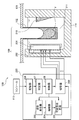
- FIG. 2 is a diagram showing an example of a specific configuration of the stirring mechanism 109 provided in the chemical analyzer 100 shown in FIG.
- the stirring mechanism 109 includes a piezoelectric element 201, a plurality of ultrasonic elements 202 (see FIG. 4, 202_1, 202_2... 202_10), a reflection unit 210, a driving device 220, and the like.
- the driving device 220 includes a waveform generator 203, an amplifier 204, a variable matching circuit 205, a storage unit 206, a determiner 207, a controller 208, a switch 209, and the like.
- the piezoelectric element 201 is provided so as to face the side surface of the reaction vessel 102 along the inner wall of the constant temperature bath 114 filled with the constant temperature water 211.
- a piezoelectric element 201 is provided along one inner wall of the thermostat 114, and a reflection means 210 is provided along the other inner wall of the thermostat 114.
- the reaction vessel 102 is disposed between the piezoelectric element 201 and the reflection means 210.
- the piezoelectric element 201 includes a piezoelectric film and electrodes formed on both surfaces of the piezoelectric film. When a voltage is applied between the two electrodes, the piezoelectric film vibrates, and ultrasonic waves having a predetermined frequency are emitted from the piezoelectric element 201 to the side surface of the reaction vessel 102. Ultrasonic waves generated on the side surface of the piezoelectric element 201 are reflected by the reflection means 210 and supplied to the reaction vessel 102. The ultrasonic waves supplied to the reaction vessel 102 are irradiated from the side surface of the reaction vessel 102 downward, and agitate the liquid such as the sample in the reaction vessel 102. Accordingly, the stirring mechanism 109 can stir the object to be stirred in the reaction vessel 102 without contact.
- the piezoelectric element 201 is applied with a voltage having an amplitude-modulated waveform from the driving device 220, and irradiates the side surface of the reaction vessel 102 with ultrasonic waves based on the voltage (change in amplitude).
- the irradiated ultrasonic wave propagates inside the constant temperature water 211 in the wall of the constant temperature bath 114, is transmitted to the reaction container 102, and enters the reaction container 102.
- a force acts such that the liquid jumps out to the gas side (acoustic radiation pressure is a main factor).
- the voltage of the amplitude-modulated waveform is applied from the driving device 220 to the piezoelectric element 201.
- the ultrasonic waves emitted from the piezoelectric element 201 to the reaction vessel 102 also correspond to the amplitude change.
- the ultrasonic wave reflected by the reflection means 210 and incident on the reaction vessel 102 is set in a direction in which there is no liquid surface in the traveling direction.
- the plurality of ultrasonic elements 202 have a structure in which segments are arranged in an array so that the ultrasonic elements (202_1, 202_2,..., 202_10) can be driven independently.
- the waveform generator 203 generates an ultrasonic waveform based on information on the amount of liquid to be stirred in the reaction vessel 102 (that is, the amount of the dispensed sample and reagent) and the timing of stirring, which are input from the controller 208. Then, the signal is output to the amplifier 204.
- the variable matching circuit 205 matches the impedance between the waveform generator 203 and the ultrasonic element 202 to be driven based on the determination result.
- the variable matching circuit 205 calculates the liquid level of the liquid to be measured filled in the reaction vessel 102 from the information on the liquid amount, and determines the optimal ultrasonic irradiation area including the liquid level.
- the variable matching circuit 205 matches the impedance of the ultrasonic element 202 with the impedance of the driving device 220. Thereby, the reflected power to the driving device 220 can be reduced, and the durability of the driving device 220 can be improved.
- Sample information is input from the console 113.
- the sample information is information necessary for setting stirring conditions, and includes, for example, information on the amount of a sample, information on viscosity, information on the amount of a reagent, and the like.
- the storage unit 206 stores the correspondence information between the sample information and the stirring information.
- the stirring information is information such as the position and the number of the ultrasonic elements 202 to be driven at the time of stirring. By providing the storage unit 206 in this manner, it is possible to store an appropriate stirring condition for the sample information.
- the determiner 207 determines the position and number of the ultrasonic elements 202 to be driven from among the plurality of ultrasonic elements 202 so that the height at which the ultrasonic waves propagate is adjusted with a resolution equal to or less than the height of the ultrasonic elements 202. Is determined based on the correspondence information stored in the storage unit 206. The determiner 207 outputs this determination result to the controller 208 as transmission information. By collating the storage unit 206 in this manner, the determiner 207 can determine the stirring condition without having to calculate the stirring condition each time the determination is made.
- the controller 208 generates a control signal based on the transmission information input from the determiner 207, and outputs the control signal to the waveform generator 203, the variable matching circuit 205, and the switch 209.
- the switch 209 controls ON / OFF of the ultrasonic element 202 driven by the piezoelectric element 201 based on a control signal input from the controller 208.
- the switch 209 selects the ultrasonic element 202 (the ultrasonic element 202 to be driven) corresponding to the ultrasonic irradiation area from the plurality of ultrasonic elements 202. Thereby, a predetermined ultrasonic element 202 is driven.
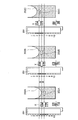
- FIG. 3 is a cross-sectional view for explaining the principle of ultrasonic stirring according to the chemical analyzer of the comparative example.
- FIG. 4 is a cross-sectional view for explaining the principle of ultrasonic stirring according to the chemical analyzer 100 of the present embodiment. First, the principle of ultrasonic stirring according to the chemical analyzer of the comparative example will be described.
- a combination of the plurality of ultrasonic elements 202 is selected so that the ultrasonic wave propagates to the gas-liquid interface of the sample.
- a fixed number of elements are selected such that the energy transfer from the drive circuit to the group of elements is constant. Therefore, the height resolution at which the ultrasonic wave propagates depends on the element width of the ultrasonic element 202.
- the chemical analyzer of the comparative example drives the ultrasonic elements 202_5, 202_6, and 202_7 in the piezoelectric element 201.
- the acoustic stream 303A due to the ultrasonic wave X coincides with the position of the gas-liquid interface of the specimen 302A. That is, the ultrasonic elements 202_5, 202_6, and 202_7 are controlled such that the acoustic stream 303A is generated at the position of the gas-liquid interface of the specimen 302A.
- the chemical analyzer of the comparative example drives the ultrasonic elements 202_4, 202_5, and 202_6 in the piezoelectric element 201.
- the acoustic stream 303B generated by the ultrasonic wave X coincides with the position of the gas-liquid interface of the specimen 302B. That is, the ultrasonic elements 202_4, 202_5, and 202_6 are controlled such that the acoustic stream 303B is generated at the position of the gas-liquid interface of the sample 302B.
- the chemical analyzer of the comparative example drives the ultrasonic elements 202_3, 202_4, and 202_5 in the piezoelectric element 201.
- the acoustic stream 303C generated by the ultrasonic wave X coincides with the position of the gas-liquid interface of the specimen 302C. That is, the ultrasonic elements 202_3, 202_4, and 202_5 are controlled such that an acoustic stream 303C is generated at the position of the gas-liquid interface of the sample 302C.
- the chemical analyzer of the comparative example controls the positions where the acoustic streams 303A to 303C are generated by the ultrasonic waves X by continuously driving the plurality of ultrasonic elements 202 by a predetermined number.
- the chemical analyzer of the comparative example matches the impedance of the ultrasonic element 202 with the impedance of the driving device 220 and stabilizes the generated ultrasonic wave X, so that the number of ultrasonic elements 202 to be driven is constant. You can only do it.
- the resolution is not higher than the height of the ultrasonic element 202.
- FIG. 4 is a cross-sectional view for explaining the principle of ultrasonic agitation according to the chemical analyzer 100 of the present embodiment.
- the chemical analyzer 100 includes the determiner 207 and the variable matching circuit 205 in order to adjust the height at which the ultrasonic wave propagates with a resolution equal to or less than the height of the ultrasonic element 202.
- the determiner 207 determines the number and position of the elements to be driven from the plurality of ultrasonic elements 202, and the variable matching circuit 205 performs impedance matching according to the determination result of the determiner 207.
- the chemical analyzer 100 drives the ultrasonic elements 202_5, 202_6, and 202_7 in the piezoelectric element 201.
- the acoustic stream 403A due to the ultrasonic wave X coincides with the position of the gas-liquid interface of the specimen 402A. That is, the ultrasonic elements 202_5, 202_6, and 202_7 are controlled such that the acoustic stream 403A is generated at the position of the gas-liquid interface of the sample 402A.
- the chemical analyzer 100 sets the ultrasonic elements 202_4, 202_5, 202_6, and 202_7 in the piezoelectric element 201. Drive.
- the acoustic stream 403B generated by the ultrasonic wave X coincides with the position of the gas-liquid interface of the specimen 402B. That is, the generation position of the ultrasonic wave X and the acoustic flow 403B is controlled with a resolution equal to or less than the height of the ultrasonic element 202, and from the central diagram in FIG.
- the generation position of the acoustic flow 403B is determined at the gas-liquid interface of the specimen 402B. It can be seen that it is closer to the position. In the center diagram of FIG. 4, it can be seen that the generation positions of the ultrasonic wave X and the acoustic stream can be controlled with higher resolution than the left diagram of FIG. That is, the chemical analyzer 100 can drive-control the ultrasonic elements 202_4, 202_5, 202_6, and 202_7 by arbitrarily matching the impedance of the ultrasonic element 202 and the impedance of the driving device 220.
- the chemical analysis apparatus 100 determines that the ultrasonic elements 202_4, 202_5, 202_6, and 202_8 in the piezoelectric element 201. Drive.
- the acoustic stream 403C generated by the ultrasonic wave X coincides with the position of the gas-liquid interface of the specimen 402C. That is, the generation position of the ultrasonic wave X and the acoustic flow 403C is controlled with a resolution equal to or less than the height of the ultrasonic element 202, and from the right diagram of FIG. It can be seen that it is closer to the position.
- FIG. 4 the chemical analysis apparatus 100 determines that the ultrasonic elements 202_4, 202_5, 202_6, and 202_8 in the piezoelectric element 201.
- the acoustic stream 403C generated by the ultrasonic wave X coincides with the position of the gas-liquid interface of the specimen 402C. That is, the generation position of the ultrasonic wave X and the acoustic flow
- the chemical analyzer 100 can drive and control the ultrasonic elements 202_4, 202_5, 202_6, and 202_8 by arbitrarily matching the impedance of the ultrasonic element 202 and the impedance of the driving device 220.
- the chemical analyzer 100 can control the position where the acoustic streams 403A to 403C are generated by the ultrasonic waves X by driving the plural ultrasonic elements 202 discontinuously by an arbitrary number.
- the chemical analyzer 100 can arbitrarily match the impedance of the ultrasonic element 202 with the impedance of the driving device 220, and can select the position and the number of the ultrasonic elements 202 to be driven each time. Therefore, the chemical analyzer 100 stirs the sample and the reagent by a method of arbitrarily controlling the position and the number of the ultrasonic elements 202 to be driven, and the ultrasonic and acoustic waves with a resolution equal to or less than the height of the ultrasonic elements 202.
- the position where the flow is generated can be controlled.
- the accuracy of setting the height of the ultrasonic element 202 to be equal to or less than the height of one ultrasonic element 202, it is possible to obtain a sufficient swirling flow and to improve the stirring effect in stirring the sample and the reagent. Become.
- the determiner 207 determines the position and number of the ultrasonic elements 202 to be driven from among the plurality of ultrasonic elements 202, and the variable matching circuit 205 determines the determination result. , Impedance matching is performed.
- the height at which the ultrasonic wave propagates can be adjusted with a resolution equal to or lower than the height of the ultrasonic element 202.
- variable matching circuit 205 is provided inside the driving device 220.
- variable matching circuit 205A is provided outside the driving device 220.
- the variable matching circuit 205A is provided between the driving device 220 and the piezoelectric element 201.
- the variable matching circuit 205A matches the impedance of the driving device 220 with the impedance of the piezoelectric element 201.
- the variable matching circuit 205A obtains a control signal from the controller 208 based on the information determined by the determiner 207 so that the electrical impedance matches at the drive frequency, and is set by a transmission signal from the controller 208. .
- the variable matching circuit 205A includes, for example, a variable resistor, a variable capacitor, a variable coil, and the like.
- the variable matching circuit 205A may be configured by an LPF (Low-pass filter) type, an HPF (High-pass filter) type, a T type, a ⁇ type, or a combination thereof. Further, the variable matching circuit 205A may be a transformer type or transmission line type matching circuit.
- variable matching circuit 205A is provided in the ultrasonic stirring mechanism, the height of the ultrasonic wave propagation and the generation of the acoustic stream are set closer to the liquid surface, as in the first embodiment. Therefore, it is possible to provide a chemical analyzer that improves the stirring performance of the sample and the reagent.
- the present invention is not limited to the embodiment and the modified examples described above, and includes various modified examples.
- the above-described embodiments and modified examples have been described in detail for easy understanding of the present invention, and are not necessarily limited to those having all the configurations described above.
- a part of the configuration of an embodiment or a modified example can be replaced with the configuration of another embodiment or a modified example. Can be added.
Landscapes
- Chemical & Material Sciences (AREA)
- Chemical Kinetics & Catalysis (AREA)
- General Health & Medical Sciences (AREA)
- Life Sciences & Earth Sciences (AREA)
- Analytical Chemistry (AREA)
- Biochemistry (AREA)
- Physics & Mathematics (AREA)
- General Physics & Mathematics (AREA)
- Immunology (AREA)
- Pathology (AREA)
- Health & Medical Sciences (AREA)
- Automatic Analysis And Handling Materials Therefor (AREA)
- Sampling And Sample Adjustment (AREA)
- Mixers With Rotating Receptacles And Mixers With Vibration Mechanisms (AREA)
Priority Applications (3)
| Application Number | Priority Date | Filing Date | Title |
|---|---|---|---|
| EP19825262.9A EP3816631B1 (de) | 2018-06-29 | 2019-05-13 | Chemische analysevorrichtung |
| CN201980028551.XA CN112041685A (zh) | 2018-06-29 | 2019-05-13 | 化学分析装置 |
| US17/255,714 US20210270707A1 (en) | 2018-06-29 | 2019-05-13 | Chemical Analysis Device |
Applications Claiming Priority (2)
| Application Number | Priority Date | Filing Date | Title |
|---|---|---|---|
| JP2018-123943 | 2018-06-29 | ||
| JP2018123943A JP7061525B2 (ja) | 2018-06-29 | 2018-06-29 | 化学分析装置 |
Publications (1)
| Publication Number | Publication Date |
|---|---|
| WO2020003769A1 true WO2020003769A1 (ja) | 2020-01-02 |
Family
ID=68986258
Family Applications (1)
| Application Number | Title | Priority Date | Filing Date |
|---|---|---|---|
| PCT/JP2019/018864 Ceased WO2020003769A1 (ja) | 2018-06-29 | 2019-05-13 | 化学分析装置 |
Country Status (5)
| Country | Link |
|---|---|
| US (1) | US20210270707A1 (de) |
| EP (1) | EP3816631B1 (de) |
| JP (1) | JP7061525B2 (de) |
| CN (1) | CN112041685A (de) |
| WO (1) | WO2020003769A1 (de) |
Cited By (3)
| Publication number | Priority date | Publication date | Assignee | Title |
|---|---|---|---|---|
| WO2022244376A1 (ja) * | 2021-05-18 | 2022-11-24 | 株式会社日立ハイテク | 自動化学分析装置、自動化学分析装置用メンテナンスキット、及び自動化学分析装置のメンテナンス方法 |
| CN115698726A (zh) * | 2020-06-18 | 2023-02-03 | 株式会社日立高新技术 | 自动化学分析装置以及电阻抗谱测定器 |
| US20250130249A1 (en) * | 2022-01-31 | 2025-04-24 | Hitachi High-Tech Corporation | Automatic Analyzer |
Families Citing this family (7)
| Publication number | Priority date | Publication date | Assignee | Title |
|---|---|---|---|---|
| JP2023097912A (ja) * | 2021-12-28 | 2023-07-10 | 株式会社日立ハイテク | 化学分析装置、化学分析方法 |
| JP2023128080A (ja) * | 2022-03-02 | 2023-09-14 | 富士レビオ株式会社 | 検体分析装置及び検体分析方法 |
| JP7791768B2 (ja) * | 2022-04-20 | 2025-12-24 | 株式会社日立ハイテク | 自動分析装置 |
| JP2024100437A (ja) * | 2023-01-16 | 2024-07-26 | 株式会社日立ハイテク | 自動分析装置、及び異常診断方法 |
| CN116500282A (zh) * | 2023-02-28 | 2023-07-28 | 迈克医疗电子有限公司 | 样本分析仪 |
| CN116500286A (zh) * | 2023-05-09 | 2023-07-28 | 江苏英诺华医疗技术有限公司 | 一种具有超声波功能的全自动生化仪及应用方法 |
| CN118080463A (zh) * | 2024-01-19 | 2024-05-28 | 中国科学院深圳先进技术研究院 | 一种多通道、自动化化学合成、磁吸及原位清洗装置 |
Citations (9)
| Publication number | Priority date | Publication date | Assignee | Title |
|---|---|---|---|---|
| JPH08146007A (ja) | 1994-09-20 | 1996-06-07 | Hitachi Ltd | 化学分析装置 |
| JP2003254981A (ja) * | 2002-03-01 | 2003-09-10 | Hitachi High-Technologies Corp | 化学分析装置及び化学分析方法 |
| JP2003254979A (ja) | 2002-02-28 | 2003-09-10 | Hitachi High-Technologies Corp | 自動分析装置 |
| JP2006234839A (ja) | 2006-05-25 | 2006-09-07 | Hitachi High-Technologies Corp | 化学分析装置 |
| JP2007108062A (ja) * | 2005-10-14 | 2007-04-26 | Olympus Corp | 攪拌装置、容器及び分析装置 |
| JP2009002918A (ja) | 2007-06-25 | 2009-01-08 | Olympus Corp | 音波発生体、攪拌装置及び自動分析装置 |
| WO2009005066A1 (ja) * | 2007-07-02 | 2009-01-08 | Olympus Corporation | 音波発生部材、容器および分析装置 |
| JP2015025678A (ja) | 2013-07-24 | 2015-02-05 | 株式会社日立ハイテクノロジーズ | 自動分析装置 |
| WO2016132798A1 (ja) * | 2015-02-19 | 2016-08-25 | 株式会社 日立ハイテクノロジーズ | 自動分析装置 |
Family Cites Families (8)
| Publication number | Priority date | Publication date | Assignee | Title |
|---|---|---|---|---|
| JP3661076B2 (ja) * | 1998-11-18 | 2005-06-15 | 株式会社日立製作所 | 化学分析装置 |
| JP3607557B2 (ja) * | 2000-02-25 | 2005-01-05 | 株式会社日立製作所 | 自動分析装置 |
| JP4085230B2 (ja) * | 2001-01-15 | 2008-05-14 | 株式会社日立製作所 | 撹拌装置及びその撹拌装置を備えた分析装置 |
| JP2007010345A (ja) * | 2005-06-28 | 2007-01-18 | Olympus Corp | 攪拌装置、攪拌方法及び攪拌装置を備えた分析装置 |
| JP2007040843A (ja) * | 2005-08-03 | 2007-02-15 | Hitachi High-Technologies Corp | 自動分析装置 |
| EP1947462A1 (de) * | 2005-10-14 | 2008-07-23 | Olympus Corporation | Rührer, gefäss und analysegerät |
| JP4887174B2 (ja) * | 2007-02-19 | 2012-02-29 | 株式会社日立ハイテクノロジーズ | 自動分析装置 |
| JP5274188B2 (ja) * | 2008-10-03 | 2013-08-28 | ベックマン コールター, インコーポレイテッド | 攪拌装置及び分析装置 |
-
2018
- 2018-06-29 JP JP2018123943A patent/JP7061525B2/ja active Active
-
2019
- 2019-05-13 CN CN201980028551.XA patent/CN112041685A/zh not_active Withdrawn
- 2019-05-13 WO PCT/JP2019/018864 patent/WO2020003769A1/ja not_active Ceased
- 2019-05-13 US US17/255,714 patent/US20210270707A1/en not_active Abandoned
- 2019-05-13 EP EP19825262.9A patent/EP3816631B1/de active Active
Patent Citations (9)
| Publication number | Priority date | Publication date | Assignee | Title |
|---|---|---|---|---|
| JPH08146007A (ja) | 1994-09-20 | 1996-06-07 | Hitachi Ltd | 化学分析装置 |
| JP2003254979A (ja) | 2002-02-28 | 2003-09-10 | Hitachi High-Technologies Corp | 自動分析装置 |
| JP2003254981A (ja) * | 2002-03-01 | 2003-09-10 | Hitachi High-Technologies Corp | 化学分析装置及び化学分析方法 |
| JP2007108062A (ja) * | 2005-10-14 | 2007-04-26 | Olympus Corp | 攪拌装置、容器及び分析装置 |
| JP2006234839A (ja) | 2006-05-25 | 2006-09-07 | Hitachi High-Technologies Corp | 化学分析装置 |
| JP2009002918A (ja) | 2007-06-25 | 2009-01-08 | Olympus Corp | 音波発生体、攪拌装置及び自動分析装置 |
| WO2009005066A1 (ja) * | 2007-07-02 | 2009-01-08 | Olympus Corporation | 音波発生部材、容器および分析装置 |
| JP2015025678A (ja) | 2013-07-24 | 2015-02-05 | 株式会社日立ハイテクノロジーズ | 自動分析装置 |
| WO2016132798A1 (ja) * | 2015-02-19 | 2016-08-25 | 株式会社 日立ハイテクノロジーズ | 自動分析装置 |
Non-Patent Citations (1)
| Title |
|---|
| See also references of EP3816631A4 |
Cited By (6)
| Publication number | Priority date | Publication date | Assignee | Title |
|---|---|---|---|---|
| CN115698726A (zh) * | 2020-06-18 | 2023-02-03 | 株式会社日立高新技术 | 自动化学分析装置以及电阻抗谱测定器 |
| EP4170351A4 (de) * | 2020-06-18 | 2024-05-22 | Hitachi High-Tech Corporation | Automatische chemische analysevorrichtung und elektrische impedanzspektrometrievorrichtung |
| WO2022244376A1 (ja) * | 2021-05-18 | 2022-11-24 | 株式会社日立ハイテク | 自動化学分析装置、自動化学分析装置用メンテナンスキット、及び自動化学分析装置のメンテナンス方法 |
| JP2022177414A (ja) * | 2021-05-18 | 2022-12-01 | 株式会社日立ハイテク | 自動化学分析装置、自動化学分析装置用メンテナンスキット、及び自動化学分析装置のメンテナンス方法 |
| JP7665406B2 (ja) | 2021-05-18 | 2025-04-21 | 株式会社日立ハイテク | 自動化学分析装置、自動化学分析装置用メンテナンスキット、及び自動化学分析装置のメンテナンス方法 |
| US20250130249A1 (en) * | 2022-01-31 | 2025-04-24 | Hitachi High-Tech Corporation | Automatic Analyzer |
Also Published As
| Publication number | Publication date |
|---|---|
| EP3816631A4 (de) | 2022-04-20 |
| EP3816631A1 (de) | 2021-05-05 |
| CN112041685A (zh) | 2020-12-04 |
| JP7061525B2 (ja) | 2022-04-28 |
| JP2020003378A (ja) | 2020-01-09 |
| EP3816631B1 (de) | 2024-03-13 |
| US20210270707A1 (en) | 2021-09-02 |
Similar Documents
| Publication | Publication Date | Title |
|---|---|---|
| WO2020003769A1 (ja) | 化学分析装置 | |
| JP3828818B2 (ja) | 化学分析装置及び化学分析方法 | |
| CN101946181B (zh) | 自动分析装置 | |
| JP2009025248A (ja) | 自動分析装置及び分注方法 | |
| JP3704035B2 (ja) | 自動分析装置 | |
| EP1990640A1 (de) | Rühr- und analysegerät | |
| JP2001215232A (ja) | 化学分析装置 | |
| JP4085230B2 (ja) | 撹拌装置及びその撹拌装置を備えた分析装置 | |
| JP6966337B2 (ja) | 化学分析装置、及び、当該化学分析装置に用いる音波攪拌機構 | |
| JP2007010345A (ja) | 攪拌装置、攪拌方法及び攪拌装置を備えた分析装置 | |
| WO2007088673A1 (ja) | 位置検出装置、位置検出方法及び分析装置 | |
| JP2009002918A (ja) | 音波発生体、攪拌装置及び自動分析装置 | |
| JP4406629B2 (ja) | 化学分析装置 | |
| JP4045452B2 (ja) | 化学分析装置 | |
| JP5668021B2 (ja) | 自動分析装置 | |
| JP2007057318A (ja) | 分析装置、供給装置、攪拌装置及び攪拌方法 | |
| WO2010106998A1 (ja) | 攪拌装置、自動分析装置及び攪拌方法 | |
| JP7734762B2 (ja) | 自動分析装置 | |
| Katou et al. | Non-contact micro-liquid mixing method using ultrasound | |
| JP6858096B2 (ja) | 化学分析装置 | |
| JP5919364B2 (ja) | 自動分析装置 | |
| WO2007097174A1 (ja) | 攪拌装置と分析装置 | |
| JP3121829U (ja) | 自動分析装置 | |
| JP2008128743A (ja) | 水晶振動子を使用した液状物の撹拌方法 | |
| JP2007205816A (ja) | 分析装置と分析装置の測光方法 |
Legal Events
| Date | Code | Title | Description |
|---|---|---|---|
| 121 | Ep: the epo has been informed by wipo that ep was designated in this application |
Ref document number: 19825262 Country of ref document: EP Kind code of ref document: A1 |
|
| NENP | Non-entry into the national phase |
Ref country code: DE |
|
| WWE | Wipo information: entry into national phase |
Ref document number: 2019825262 Country of ref document: EP |