WO2020003852A1 - Accumulateur de compresseur, procédé de fabrication d'accumulateur de compresseur, compresseur horizontal, et dispositif à cycle frigorifique - Google Patents
Accumulateur de compresseur, procédé de fabrication d'accumulateur de compresseur, compresseur horizontal, et dispositif à cycle frigorifique Download PDFInfo
- Publication number
- WO2020003852A1 WO2020003852A1 PCT/JP2019/020972 JP2019020972W WO2020003852A1 WO 2020003852 A1 WO2020003852 A1 WO 2020003852A1 JP 2019020972 W JP2019020972 W JP 2019020972W WO 2020003852 A1 WO2020003852 A1 WO 2020003852A1
- Authority
- WO
- WIPO (PCT)
- Prior art keywords
- compressor
- accumulator
- refrigerant
- axial direction
- housing
- Prior art date
- Legal status (The legal status is an assumption and is not a legal conclusion. Google has not performed a legal analysis and makes no representation as to the accuracy of the status listed.)
- Ceased
Links
Images






Classifications
-
- F—MECHANICAL ENGINEERING; LIGHTING; HEATING; WEAPONS; BLASTING
- F04—POSITIVE - DISPLACEMENT MACHINES FOR LIQUIDS; PUMPS FOR LIQUIDS OR ELASTIC FLUIDS
- F04C—ROTARY-PISTON, OR OSCILLATING-PISTON, POSITIVE-DISPLACEMENT MACHINES FOR LIQUIDS; ROTARY-PISTON, OR OSCILLATING-PISTON, POSITIVE-DISPLACEMENT PUMPS
- F04C29/00—Component parts, details or accessories of pumps or pumping installations, not provided for in groups F04C18/00 - F04C28/00
- F04C29/02—Lubrication; Lubricant separation
-
- F—MECHANICAL ENGINEERING; LIGHTING; HEATING; WEAPONS; BLASTING
- F04—POSITIVE - DISPLACEMENT MACHINES FOR LIQUIDS; PUMPS FOR LIQUIDS OR ELASTIC FLUIDS
- F04C—ROTARY-PISTON, OR OSCILLATING-PISTON, POSITIVE-DISPLACEMENT MACHINES FOR LIQUIDS; ROTARY-PISTON, OR OSCILLATING-PISTON, POSITIVE-DISPLACEMENT PUMPS
- F04C29/00—Component parts, details or accessories of pumps or pumping installations, not provided for in groups F04C18/00 - F04C28/00
- F04C29/12—Arrangements for admission or discharge of the working fluid, e.g. constructional features of the inlet or outlet
-
- F—MECHANICAL ENGINEERING; LIGHTING; HEATING; WEAPONS; BLASTING
- F25—REFRIGERATION OR COOLING; COMBINED HEATING AND REFRIGERATION SYSTEMS; HEAT PUMP SYSTEMS; MANUFACTURE OR STORAGE OF ICE; LIQUEFACTION SOLIDIFICATION OF GASES
- F25B—REFRIGERATION MACHINES, PLANTS OR SYSTEMS; COMBINED HEATING AND REFRIGERATION SYSTEMS; HEAT PUMP SYSTEMS
- F25B1/00—Compression machines, plants or systems with non-reversible cycle
-
- F—MECHANICAL ENGINEERING; LIGHTING; HEATING; WEAPONS; BLASTING
- F25—REFRIGERATION OR COOLING; COMBINED HEATING AND REFRIGERATION SYSTEMS; HEAT PUMP SYSTEMS; MANUFACTURE OR STORAGE OF ICE; LIQUEFACTION SOLIDIFICATION OF GASES
- F25B—REFRIGERATION MACHINES, PLANTS OR SYSTEMS; COMBINED HEATING AND REFRIGERATION SYSTEMS; HEAT PUMP SYSTEMS
- F25B43/00—Arrangements for separating or purifying gases or liquids; Arrangements for vaporising the residuum of liquid refrigerant, e.g. by heat
-
- F—MECHANICAL ENGINEERING; LIGHTING; HEATING; WEAPONS; BLASTING
- F25—REFRIGERATION OR COOLING; COMBINED HEATING AND REFRIGERATION SYSTEMS; HEAT PUMP SYSTEMS; MANUFACTURE OR STORAGE OF ICE; LIQUEFACTION SOLIDIFICATION OF GASES
- F25B—REFRIGERATION MACHINES, PLANTS OR SYSTEMS; COMBINED HEATING AND REFRIGERATION SYSTEMS; HEAT PUMP SYSTEMS
- F25B43/00—Arrangements for separating or purifying gases or liquids; Arrangements for vaporising the residuum of liquid refrigerant, e.g. by heat
- F25B43/02—Arrangements for separating or purifying gases or liquids; Arrangements for vaporising the residuum of liquid refrigerant, e.g. by heat for separating lubricants from the refrigerant
Definitions
- the embodiments of the present invention relate to an accumulator for a compressor, a method for manufacturing the accumulator for a compressor, a horizontal compressor, and a refrigeration cycle apparatus having the horizontal compressor.
- the horizontal compressor is a cylindrical hermetic container, a compression mechanism portion housed inside the hermetic container and compressing the refrigerant, and an electric motor portion housed inside the hermetic container and driving the compression mechanism portion via a rotating shaft.
- the horizontal compressor includes an accumulator for the compressor, a refrigerant inlet pipe for sucking the refrigerant into the accumulator for the compressor, and a suction pipe for returning the refrigerant from which the oil has been separated by the accumulator for the compressor to a closed container. are doing.
- An oil return hole is formed in the suction pipe to return the refrigerating machine oil separated from the refrigerant to the closed container inside the compressor accumulator.
- the refrigerant oil is separated by the compressor accumulator before the refrigerant is returned to the closed container.
- the refrigerant from which the refrigerating machine oil has been separated is returned to the closed container via the suction pipe.
- the refrigerating machine oil separated from the refrigerant is returned to the closed container via the oil return hole.
- An object of the present invention is to provide a horizontal compressor in which refrigerating machine oil separated from a refrigerant is easily returned to a closed container.
- the compressor accumulator has a tubular housing arranged in a horizontal position, and a refrigerant inlet pipe connected to one axial side of the housing and sucking refrigerant into the housing.
- a suction pipe connected to the other side of the housing in the axial direction along a direction intersecting the axial direction, and a suction pipe that guides the refrigerant to a compressor.
- An oil return hole for returning the refrigerating machine oil separated from the refrigerant to the compressor is formed, and the oil return hole is opened so that at least a part thereof faces the opening direction of the refrigerant inlet pipe.
- FIG. 1 is a circuit diagram schematically illustrating a configuration of a refrigeration cycle apparatus according to the embodiment.
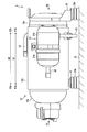
- FIG. 2 is a side view of the horizontal compressor according to the embodiment.
- FIG. 3 is a cross-sectional view showing the horizontal compressor according to the embodiment from the side.
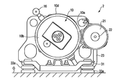
- FIG. 4 is a front view of the horizontal compressor as viewed from the direction of arrow F4 in FIG.
- FIG. 5 is a rear view of the horizontal compressor as viewed from the direction of arrow F5 in FIG.
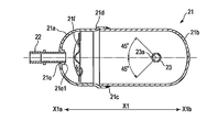
- FIG. 6 is a cross-sectional view illustrating a positional relationship among an accumulator for a compressor, a refrigerant inlet pipe, and a suction pipe according to the embodiment.
- FIG. 7 is a sectional view taken along line F7-F7 of FIG. FIG.
- FIG. 8 is a cross-sectional view showing a positional relationship between the compressor accumulator and the suction pipe according to the embodiment.
- FIG. 9 is a cross-sectional view illustrating a positional relationship among a compressor accumulator, a refrigerant inlet pipe, and a suction pipe according to a first modification of the embodiment.
- FIG. 10 is a cross-sectional view illustrating a positional relationship among an accumulator for a compressor, a refrigerant inlet pipe, and a suction pipe according to a second modification of the embodiment.
- FIG. 1 is a refrigeration cycle circuit diagram of an air conditioner 1 which is an example of a refrigeration cycle device.
- the air conditioner 1 includes a horizontal compressor 2, a four-way valve 3, an outdoor heat exchanger 4, an expansion device 5, and an indoor heat exchanger 6 as main elements.
- a plurality of elements constituting the air conditioner 1 are connected via a circulation circuit 7 through which a refrigerant circulates.
- the discharge side of the horizontal compressor 2 is connected to the first port 3 a of the four-way valve 3.
- the second port 3 b of the four-way valve 3 is connected to the outdoor heat exchanger 4.
- the outdoor heat exchanger 4 is connected to an indoor heat exchanger 6 via an expansion device 5.
- the indoor heat exchanger 6 is connected to the third port 3c of the four-way valve 3.
- the fourth port 3d of the four-way valve 3 is connected to the suction side of the horizontal compressor 2 via a compressor accumulator 21.
- the four-way valve 3 switches so that the first port 3a communicates with the second port 3b and the third port 3c communicates with the fourth port 3d.
- the high-temperature and high-pressure gas-phase refrigerant compressed by the horizontal compressor 2 is discharged to the circulation circuit 7.
- the discharged gas-phase refrigerant is guided via the four-way valve 3 to the outdoor heat exchanger 4 functioning as a radiator (condenser).
- the gas-phase refrigerant guided to the outdoor heat exchanger 4 is condensed by heat exchange with air and changes into a high-pressure liquid-phase refrigerant.
- the high-pressure liquid-phase refrigerant is reduced in pressure in the process of passing through the expansion device 5 and changes to a low-pressure gas-liquid two-phase refrigerant.
- the gas-liquid two-phase refrigerant is guided to the indoor heat exchanger 6 functioning as a heat absorber (evaporator), and exchanges heat with air while passing through the indoor heat exchanger 6.
- the gas-liquid two-phase refrigerant takes heat from the air, evaporates, and changes to a low-temperature, low-pressure gas-phase refrigerant.
- the air passing through the indoor heat exchanger 6 is cooled by the latent heat of vaporization of the liquid-phase refrigerant, becomes cool air, and is sent to a place to be air-conditioned (cooled).
- the low-temperature and low-pressure gas-phase refrigerant that has passed through the indoor heat exchanger 6 is guided to the compressor accumulator 21 via the four-way valve 3. If the liquid-phase refrigerant that has not completely evaporated is mixed in the refrigerant, it is separated here into a liquid-phase refrigerant and a gas-phase refrigerant.
- the low-temperature and low-pressure gas-phase refrigerant separated from the liquid-phase refrigerant is drawn into the horizontal compressor 2 from the compressor accumulator 21, and is again converted into a high-temperature and high-pressure gas-phase refrigerant by the horizontal compressor 2. It is compressed and discharged to the circulation circuit 7.
- the four-way valve 3 switches so that the first port 3a communicates with the third port 3c and the second port 3b communicates with the fourth port 3d.
- the high-temperature and high-pressure gas-phase refrigerant discharged from the horizontal compressor 2 is guided to the indoor heat exchanger 6 via the four-way valve 3, The heat is exchanged with the air passing through the indoor heat exchanger 6. That is, the indoor heat exchanger 6 functions as a condenser.
- the gas-phase refrigerant passing through the indoor heat exchanger 6 is condensed by exchanging heat with air, and changes into a high-pressure liquid-phase refrigerant.
- the air passing through the indoor heat exchanger 6 is heated by heat exchange with the gas-phase refrigerant and is sent to a place to be air-conditioned (heated) as hot air.
- the high-temperature liquid-phase refrigerant that has passed through the indoor heat exchanger 6 is guided to the expansion device 5, and is decompressed in the process of passing through the expansion device 5 and changes to a low-pressure gas-liquid two-phase refrigerant.
- the gas-liquid two-phase refrigerant is guided to the outdoor heat exchanger 4 functioning as an evaporator, where it is evaporated by exchanging heat with air, and changes to a low-temperature, low-pressure gas-phase refrigerant.
- the low-temperature and low-pressure gas-phase refrigerant that has passed through the outdoor heat exchanger 4 is sucked into the horizontal compressor 2 via the four-way valve 3 and the compressor accumulator 21.
- the horizontal compressor 2 is a rotary compressor that is installed in a horizontal orientation on a horizontal or nearly horizontal installation surface G, and includes a hermetic container 10, a compression mechanism 11, and a motor 12 as main elements. ing.
- the closed container 10 is supported in a horizontal position.
- the closed container 10 includes three members: a container body 10a, a first lid member 10b, and a second lid member 10c.
- the closed container 10 has a first lid member 10b shield-welded from one side X2a along the axial direction X2 to a cylindrical container body 10a having both ends opened, and a second lid Xb from the other side X2b along the axial direction X2.
- the two lid members 10c are shield-welded to maintain airtightness.
- the compression mechanism 11 and the electric motor 12 are accommodated inside the sealed container 10 in a line in the axial direction X2.
- polyalkylene glycol (PAG: polyalkylene glycol) is stored as refrigerating machine oil 40 inside closed container 10.
- the kinematic viscosity V of the polyalkylene glycol is, for example, 80 to 120 mm 2 / s at 40 ° C.
- the compression mechanism 11 is housed inside the container body 10a.
- the compression mechanism 11 is provided with a cylinder body 11a through which the crankshaft 13a of the rotating shaft 13 is inserted.
- the roller 11b is fitted on the outer peripheral surface of the crankshaft 13a.
- the cylinder body 11a has a compression chamber 11c for compressing the gas-phase refrigerant sucked from the compressor accumulator 21 via the suction pipe 23 between the cylinder body 11a and the roller 11b.
- the compression chamber 11c in which the roller 11b rotates eccentrically corresponds to the cylinder chamber 11R.
- the compression mechanism 11 has only one cylinder chamber 11R.
- the gas-phase refrigerant compressed in the compression chamber 11c is discharged into the discharge muffler 11h via the discharge valve device 15, and is discharged from the discharge muffler 11h into the closed container 10.
- the refrigerant is made of, for example, R744 which is carbon dioxide.
- the compression mechanism 11 is provided with a main bearing 11d and a sub bearing 11e that rotatably support the rotating shaft 13 so as to be arranged in the axial direction X2.
- the compression mechanism section 11 is provided with a partition member 11f that hermetically partitions a space on the compression mechanism section 11 side and a space on the electric motor section 12 side.
- the partition member 11f is an example of a partition.
- the partition member 11f is also a member that fixes the cylinder body 11a to the inner wall of the closed casing 10.
- the cylinder body 11a is fixed to the partition member 11f by a plurality of bolts 11g.
- a main bearing 11d and a sub-bearing 11e are fixed to the cylinder body 11a.
- the electric motor section 12 is an element for driving the compression mechanism section 11 and is connected to the compression mechanism section 11 via the rotating shaft 13.
- the motor unit 12 is housed inside the container body 10a at a position closer to the first lid member 10b than the compression mechanism unit 11.
- the electric motor unit 12 is, for example, a brushless DC motor.
- the motor section 12 includes a rotor 12b having a permanent magnet embedded therein and formed into a cylindrical shape, and a stator 12c surrounding the rotor 12b and having a plurality of teeth wound around a plurality of teeth.
- the rotating shaft 13 is inserted and joined to the rotor 12b.
- the rotating shaft 13 transmits the rotating motion of the electric motor unit 12 to the compression mechanism unit 11.
- the rotary shaft 13 is formed with a circular oil supply passage 13b.
- the oil supply passage 13b is a non-penetrating hole extending from the end of the compression mechanism 11 toward the electric motor 12 along the axial direction X2.
- An oil suction pipe 14 extending to the refrigerating machine oil 40 stored in the closed container 10 is connected to the oil supply passage 13 b of the rotating shaft 13.
- the oil suction pipe 14 does not follow the rotation of the rotating shaft 13.
- the rotating shaft 13 has a plurality of oil supply holes 13c penetrating from the outer peripheral surface to the oil supply passage 13b.
- the discharge pipe 16 is attached to the container body 10a.
- the discharge pipe 16 is opened inside the container body 10a at a position corresponding to the compression mechanism section 11.
- the compressor accumulator 21 is attached to the sealed container 10 in a horizontal position.
- a refrigerant inlet pipe 22 is connected to one side X1a of the compressor accumulator 21 along the axial direction X1.
- a suction pipe 23 is connected to the other side X1b of the compressor accumulator 21 along a vertical direction crossing the axial direction X1.
- the compressor accumulator 21 forms a cylindrical housing, and includes a first housing part 21a located on one side X1a and a second housing located on the other side X1b.
- the portion 21b is shield-welded along the axial direction X1.
- the first housing portion 21a has a first opening 21c in a direction facing the other side X1b.
- the first housing portion 21a has a first connection hole 21e formed at an end on one side X1a.
- the first connection hole 21e is a through hole formed by burring from one side X1a to the other side X1b of the first housing portion 21a, and has a rising portion 21e1 inside the first housing portion 21a. I have.
- a filter 21f is provided inside the first housing 21a so as to face the first connection hole 21e.
- the second housing portion 21b has a second opening 21d in a direction facing one side X1a.
- the second housing portion 21b has a second connection hole 21g formed below the other side X1b.
- the second connection hole 21g is a through-hole that is burred upward from below the other side X1b of the second housing portion 21b, and has a rising portion 21g1 inside the second housing portion 21b. I have.
- the refrigerant inlet pipe 22 is inserted into the first connection hole 21e of the first housing portion 21a along the axial direction X1 of the accumulator 21 for the compressor, and connected by brazing. I have.
- the refrigerant inlet pipe 22 is located on one side X1a in the axial direction X1 of the compressor accumulator 21, and sucks the refrigerant including the refrigerating machine oil 40 circulated from the circulation circuit 7 into the compressor accumulator 21.
- the suction pipe 23 is inserted into the second connection hole 21g of the second housing portion 21b along the vertical direction and connected by brazing.
- the suction pipe 23 is located on the other side X1b in the axial direction X1 of the compressor accumulator 21, and returns the refrigerant from which the refrigerating machine oil 40 has been separated from the compressor accumulator 21 to the closed container 10.
- the suction pipe 23 is connected to a position Xd farther from the first housing portion 21a than a center position Xc of the entire length La along the axial direction X1 of the second housing portion 21b. .
- the suction pipe 23 is formed with an oil return hole 23 a that returns a part of the refrigerating machine oil 40 separated from the refrigerant inside the compressor accumulator 21 to the closed container 10. .
- the oil return hole 23a is opened so that at least a part thereof faces the opening direction of the refrigerant inlet pipe 22.
- the oil return hole 23a opens from the one side X1a of the compressor accumulator 21 to the other side X1b with respect to the suction pipe 23.
- the oil return hole 23a is formed in a range of, for example, ⁇ 45 ° with respect to the suction pipe 23 with respect to the opening direction of the refrigerant inlet pipe 22.
- the oil return hole 23a formed in the suction pipe 23 is closed. At least some can be recognized. In other words, at least a part of the oil return hole 23a is opened toward the refrigerant inlet pipe 22.
- the first leg 31 and the second leg 32 support the closed container 10 on the installation surface G in a horizontal position via support members 33a and 33b, respectively.
- the first leg 31 is an integrally molded product obtained by subjecting a metal plate material such as a cold-rolled steel plate or a hot-rolled steel plate to sheet metal press working, and is provided on one side of the sealed container 10 corresponding to the electric motor unit 12.
- X2a The second leg 32 is an integrally molded product obtained by subjecting a metal plate such as a cold-rolled steel plate or a hot-rolled steel plate to a sheet metal press process, and is the other end of the sealed container 10 corresponding to the compression mechanism unit 11. It is fixed to the side X2b.
- the support member 33a is provided between the first leg 31 and the installation surface G. As shown in FIGS. 3 and 4, the support member 33a is provided at both ends of the first leg 31 orthogonal to the axial direction X2 on a horizontal plane at a position on one side X2a along the axial direction X2 than the electric motor unit 12. It is provided and supports the closed container 10 on the installation surface G via the first leg 31. As shown in FIGS. 3 and 5, the support member 33b is provided at both ends of the second leg 32 orthogonal to the axial direction X2 on a horizontal plane at a position on the other side X2b along the axial direction X2 than the cylinder chamber 11R. It is provided and supports the closed container 10 on the installation surface G via the second leg 32. Therefore, the support members 33a and 33b are arranged at the four corners of the closed container 10.
- the support members 33a and 33b of the present embodiment are made of, for example, butyl rubber.
- the spring constant of the support members 33a and 33b is, for example, 15 to 35 N / mm at a normal temperature of 20 ° C.
- the spring constant of each of the support members 33a and 33b located at the four corners of the closed container 10 may be the same or different as long as it is within the range of 15 to 35 N / mm at 20 ° C.
- the refrigerant inlet pipe 22 is connected to one side X1a of the accumulator 21 for the compressor in the axial direction X1.
- the suction pipe 23 is connected to the other side X1b in the axial direction X1 of the compressor accumulator 21 along a direction crossing the axial direction X1.
- the oil return hole 23 a formed in the suction pipe 23 is opened so that at least a part thereof faces the opening direction of the refrigerant inlet pipe 22.
- the oil return hole 23a formed in the suction pipe 23 is located so as to face the refrigerant inlet pipe 22. Therefore, the refrigerating machine oil 40 contained in the refrigerant sucked from the refrigerant inlet pipe 22 easily flows into the suction pipe 23 from the oil return hole 23a.
- the horizontal compressor 2 and the air conditioner 1 including the horizontal compressor 2 allow the refrigerating machine oil 40 separated from the refrigerant by the compressor accumulator 21 to pass through the suction pipe 23 to the closed container 10. Can be easily returned.
- the compressor accumulator 21 is formed by joining the first housing 21a to which the refrigerant inlet pipe 22 is connected and the second housing 21b to which the suction pipe 23 is connected.
- the suction pipe 23 is connected to a position Xd farther from the first housing portion 21a than a center position Xc of the entire length La along the axial direction X1 of the second housing portion 21b.
- the suction pipe 23 can be sufficiently separated from the refrigerant inlet pipe 22. Further, by connecting the suction pipe 23 to the position Xd, the space on the side opposite to the suction pipe 23 in the second housing portion 21b can be made sufficiently small. Thereby, the refrigerating machine oil 40 separated from the refrigerant by the compressor accumulator 21 can be prevented from wrapping around the suction pipe 23 and accumulating at the bottom. As a result, the refrigerator oil 40 can be efficiently returned to the closed container 10.
- the suction pipe 23 can be sufficiently separated from the refrigerant inlet pipe 22 in the compressor accumulator 21, the gas-liquid separation performance can be sufficiently ensured.
- the accumulator 21 for the compressor by configuring the accumulator 21 for the compressor with two pieces of the first housing part 21a and the second housing part 21b, it is possible to increase the degree of freedom in design as compared with the case where the accumulator 21 is formed with three pieces. it can.
- the reason for this is that the suction pipe 23 cannot be provided at the welded portion between the divided housing portions.
- the refrigerant comprises R744, which is carbon dioxide.
- the refrigerating machine oil 40 is made of polyalkylene glycol.
- the kinematic viscosity V of the polyalkylene glycol is 80 to 120 mm 2 / s at 40 ° C.
- the operating pressure can be increased and the torque of the motor can be increased as compared with other materials.
- the refrigerant made of R744 tends to have a higher temperature than the refrigerant made of other materials. Therefore, a polyalkylene glycol whose kinematic viscosity fluctuates less with a temperature change than a refrigerating machine oil made of another material is used.
- the accumulator 21 for the compressor has a lower temperature and a lower pressure than the closed container 10.
- the polyalkylene glycol tends to have low fluidity inside the accumulator 21 for the compressor
- the polyalkylene glycol is defined by defining the opening direction of the oil return hole 23a provided in the suction pipe 23 as described above. Glycol can be easily returned to the closed container 10 from the oil return hole 23a.
- the refrigerant made of another material is, for example, R404A.
- the refrigerating machine oil made of another material is, for example, polyvinyl ether (PVE) or polyol ester (POE).
- the compression mechanism 11 has a single cylinder chamber 11R.
- the support member 33a supports the closed container 10 on the installation surface G at a position on one side X2a along the axial direction X2 of the closed container 10 with respect to the electric motor unit 12.
- the support member 33b supports the closed container 10 on the installation surface G at a position on the other side X2b along the axial direction X2 of the closed container 10 with respect to the cylinder chamber 11R of the compression mechanism unit 11.
- the spring constant of the support members 33a and 33b is 15 to 35 N / mm at 20 ° C.
- the compression mechanism unit 11 having the single cylinder chamber 11R has a larger vibration during operation as compared with the compression mechanism unit having a plurality of cylinder chambers as a comparative example, but the vibration caused by the support members 33a and 33b. Can be sufficiently absorbed, and propagation of vibration to the installation surface G can be suppressed. As a result, noise can be sufficiently suppressed by the support members 33a and 33b.
- the support member 33a is provided at a position on one side X2a along the axial direction X2 with respect to the electric motor unit 12, deterioration due to heat generated from the electric motor unit 12 can be suppressed.
- the support member 33b is provided at a position on the other side X2b along the axial direction X2 with respect to the cylinder chamber 11R, it is possible to suppress deterioration due to heat generated from refrigerant compressed and discharged in the cylinder chamber 11R. Can be. In particular, when R744, which becomes high in temperature, is used as the refrigerant, the deterioration of the support member 33b due to heat can be effectively suppressed.
- the support members 33a and 33b can absorb and radiate the heat transmitted from the sealed container 10 to a certain extent, it is possible to suppress the transmission of heat to the installation surface G side. This is particularly effective when R744, which becomes high in temperature, is used as the refrigerant.
- the support members 33a and 33b are fixed to the closed container 10 via the first leg 31 and the second leg 32 whose surface area is increased as a shape bent so as to be folded, heat is easily radiated. In addition, deterioration due to heat can be suppressed.
- the first housing 21 a and the second housing 21 b constituting the compressor accumulator 21 are prepared.
- the suction pipe 23 is moved in the direction intersecting the axial direction X1 with the second connection hole 21g of the second housing part 21b so that the oil return hole 23a formed in the suction pipe 23 faces the first housing part 21a. Connect by brazing along.
- the suction pipe 23 is brazed to the second connection hole 21g of the second housing portion 21b, it can be easily confirmed whether or not the oil return hole 23a is closed by the wax.
- the wax can easily approach the oil return hole 23a of the suction pipe 23 along the rising portion 21g1 of the second connection hole 21g, but can be sufficiently inspected. As a result, it is possible to prevent shipment of a defective product in which the oil return hole 23a is closed by the wax.
- the identification may be based on visual recognition of an operator, or may be based on image recognition using, for example, a CCD camera.
- the horizontal compressor 2 may be installed inclined.
- the compressor accumulator 21 is relatively lower on the motor unit 12 side with respect to the axial direction X1 of the compressor accumulator 21 and relatively on the compression mechanism unit 11 side. It is provided to be inclined so as to be as high as possible. In other words, one side X1a of the compressor accumulator 21 is lower than the other side X1b.
- the compressor accumulator 21 is relatively lower on the compression mechanism unit 11 side with respect to the axial direction X1 of the compressor accumulator 21, and relatively on the electric motor unit 12 side. It is provided to be inclined so as to be higher. In other words, the other side X1b of the compressor accumulator 21 is lower than the one side X1a.
- one of the two oil return holes 23a is located lower than the other inside the compressor accumulator 21 regardless of the inclination in any direction. Therefore, the refrigerating machine oil 40 separated from the refrigerant can be returned to the closed container 10 from one of the lower oil return holes 23a.
Landscapes
- Engineering & Computer Science (AREA)
- Mechanical Engineering (AREA)
- General Engineering & Computer Science (AREA)
- Physics & Mathematics (AREA)
- Thermal Sciences (AREA)
- Chemical & Material Sciences (AREA)
- Analytical Chemistry (AREA)
- Power Engineering (AREA)
- Applications Or Details Of Rotary Compressors (AREA)
- Compressor (AREA)
Abstract
Le but de la présente invention est d'obtenir un compresseur horizontal dans lequel une huile de réfrigérateur séparée d'un fluide frigorigène peut être facilement renvoyée à un récipient scellé. Un accumulateur de compresseur (21) est équipé : d'un tuyau d'entrée de fluide frigorigène (22) qui est relié à un côté (X1a) dans la direction axiale (X1) de l'accumulateur de compresseur (21) et qui aspire un fluide frigorigène qui comprend une huile de réfrigérateur dans l'accumulateur de compresseur (21); et un tuyau d'admission (23) qui est relié à l'autre côté (X1b) dans la direction axiale (X1) de l'accumulateur de compresseur (21) dans une direction qui coupe la direction axiale (X1) et qui retourne à un compresseur, le fluide frigorigène à partir duquel l'huile de réfrigérateur a été séparée. Dans le tuyau d'admission (23), un trou de retour d'huile (23a) est formé pour permettre le retour vers le compresseur de l'huile de réfrigérateur séparée du fluide frigorigène dans l'accumulateur de compresseur (21). Le trou de retour d'huile (23a) s'ouvre de telle sorte qu'au moins une partie de celui-ci fait face à la direction d'ouverture du tuyau d'entrée de fluide frigorigène (22).
Priority Applications (1)
| Application Number | Priority Date | Filing Date | Title |
|---|---|---|---|
| JP2020527299A JP6972341B2 (ja) | 2018-06-25 | 2019-05-27 | 圧縮機用アキュムレータ、圧縮機用アキュムレータの製造方法、横置き形圧縮機および冷凍サイクル装置 |
Applications Claiming Priority (2)
| Application Number | Priority Date | Filing Date | Title |
|---|---|---|---|
| JP2018119972 | 2018-06-25 | ||
| JP2018-119972 | 2018-06-25 |
Publications (1)
| Publication Number | Publication Date |
|---|---|
| WO2020003852A1 true WO2020003852A1 (fr) | 2020-01-02 |
Family
ID=68986430
Family Applications (1)
| Application Number | Title | Priority Date | Filing Date |
|---|---|---|---|
| PCT/JP2019/020972 Ceased WO2020003852A1 (fr) | 2018-06-25 | 2019-05-27 | Accumulateur de compresseur, procédé de fabrication d'accumulateur de compresseur, compresseur horizontal, et dispositif à cycle frigorifique |
Country Status (2)
| Country | Link |
|---|---|
| JP (1) | JP6972341B2 (fr) |
| WO (1) | WO2020003852A1 (fr) |
Citations (8)
| Publication number | Priority date | Publication date | Assignee | Title |
|---|---|---|---|---|
| JPS5831266A (ja) * | 1981-08-18 | 1983-02-23 | 三洋電機株式会社 | 冷凍装置 |
| JPS59192875A (ja) * | 1984-03-12 | 1984-11-01 | Matsushita Electric Ind Co Ltd | ロ−タリ−圧縮機の振動減衰構造 |
| JPS6329071U (fr) * | 1986-08-11 | 1988-02-25 | ||
| JPS63183358A (ja) * | 1987-01-26 | 1988-07-28 | 松下電器産業株式会社 | 密閉型回転圧縮機のアキユムレ−タ |
| JPH04358778A (ja) * | 1991-03-26 | 1992-12-11 | Daikin Ind Ltd | 横形多気筒圧縮機のアキュムレータ |
| JP2001289539A (ja) * | 1999-05-24 | 2001-10-19 | Denso Corp | アキュムレータ |
| JP2005036741A (ja) * | 2003-07-16 | 2005-02-10 | Sanyo Electric Co Ltd | 横置き型圧縮機 |
| US20130255308A1 (en) * | 2012-03-29 | 2013-10-03 | Johnson Controls Technology Company | Chiller or heat pump with a falling film evaporator and horizontal oil separator |
-
2019
- 2019-05-27 WO PCT/JP2019/020972 patent/WO2020003852A1/fr not_active Ceased
- 2019-05-27 JP JP2020527299A patent/JP6972341B2/ja active Active
Patent Citations (8)
| Publication number | Priority date | Publication date | Assignee | Title |
|---|---|---|---|---|
| JPS5831266A (ja) * | 1981-08-18 | 1983-02-23 | 三洋電機株式会社 | 冷凍装置 |
| JPS59192875A (ja) * | 1984-03-12 | 1984-11-01 | Matsushita Electric Ind Co Ltd | ロ−タリ−圧縮機の振動減衰構造 |
| JPS6329071U (fr) * | 1986-08-11 | 1988-02-25 | ||
| JPS63183358A (ja) * | 1987-01-26 | 1988-07-28 | 松下電器産業株式会社 | 密閉型回転圧縮機のアキユムレ−タ |
| JPH04358778A (ja) * | 1991-03-26 | 1992-12-11 | Daikin Ind Ltd | 横形多気筒圧縮機のアキュムレータ |
| JP2001289539A (ja) * | 1999-05-24 | 2001-10-19 | Denso Corp | アキュムレータ |
| JP2005036741A (ja) * | 2003-07-16 | 2005-02-10 | Sanyo Electric Co Ltd | 横置き型圧縮機 |
| US20130255308A1 (en) * | 2012-03-29 | 2013-10-03 | Johnson Controls Technology Company | Chiller or heat pump with a falling film evaporator and horizontal oil separator |
Also Published As
| Publication number | Publication date |
|---|---|
| JP6972341B2 (ja) | 2021-11-24 |
| JPWO2020003852A1 (ja) | 2021-04-22 |
Similar Documents
| Publication | Publication Date | Title |
|---|---|---|
| US20170167737A1 (en) | Integrated air conditioner | |
| US11460234B2 (en) | Refrigerator | |
| JP2013096622A (ja) | 空気調和装置の室外ユニット | |
| US12072139B2 (en) | Refrigerator | |
| JP6972341B2 (ja) | 圧縮機用アキュムレータ、圧縮機用アキュムレータの製造方法、横置き形圧縮機および冷凍サイクル装置 | |
| EP1329675A2 (fr) | Cycle frigorifique d'une installation de climatisation | |
| US20060130512A1 (en) | Cooling-cycle device and cold/hot water dispenser comprising the same | |
| WO2023084722A1 (fr) | Compresseur et dispositif de cycle de réfrigération | |
| WO2021106198A1 (fr) | Compresseur et dispositif à cycle de réfrigération | |
| WO2023233838A1 (fr) | Compresseur et dispositif de cycle de réfrigération | |
| JP4720534B2 (ja) | 自動販売機 | |
| JP5625889B2 (ja) | 空気調和装置の室外ユニット | |
| CN100455943C (zh) | 一体型空调器 | |
| KR20130142832A (ko) | 쿨링모듈 | |
| KR20010037825A (ko) | 소음저감 창문형 에어컨 | |
| CN204494884U (zh) | 热源单元以及制冷循环装置 | |
| JP2024022594A (ja) | 冷凍システム | |
| JP7159079B2 (ja) | 密閉型圧縮機およびこれを用いた冷蔵庫 | |
| JP7087076B2 (ja) | 圧縮機および冷凍サイクル装置 | |
| WO2025088751A1 (fr) | Compresseur et dispositif à cycle de réfrigération | |
| KR20040021345A (ko) | 일체형 공기조화기의 압축기 냉각장치 | |
| CN116658398A (zh) | 压缩机以及空调机 | |
| JP2023034613A (ja) | 圧縮機、および空気調和機 | |
| WO2021210279A1 (fr) | Dispositif à cycle de réfrigération | |
| JP2015075287A (ja) | 空気調和装置 |
Legal Events
| Date | Code | Title | Description |
|---|---|---|---|
| 121 | Ep: the epo has been informed by wipo that ep was designated in this application |
Ref document number: 19826258 Country of ref document: EP Kind code of ref document: A1 |
|
| ENP | Entry into the national phase |
Ref document number: 2020527299 Country of ref document: JP Kind code of ref document: A |
|
| NENP | Non-entry into the national phase |
Ref country code: DE |
|
| 122 | Ep: pct application non-entry in european phase |
Ref document number: 19826258 Country of ref document: EP Kind code of ref document: A1 |