WO2020003853A1 - Actionneur rotatif et forceps robotique - Google Patents
Actionneur rotatif et forceps robotique Download PDFInfo
- Publication number
- WO2020003853A1 WO2020003853A1 PCT/JP2019/020996 JP2019020996W WO2020003853A1 WO 2020003853 A1 WO2020003853 A1 WO 2020003853A1 JP 2019020996 W JP2019020996 W JP 2019020996W WO 2020003853 A1 WO2020003853 A1 WO 2020003853A1
- Authority
- WO
- WIPO (PCT)
- Prior art keywords
- rotary actuator
- housing
- cover
- rotary
- rotation axis
- Prior art date
- Legal status (The legal status is an assumption and is not a legal conclusion. Google has not performed a legal analysis and makes no representation as to the accuracy of the status listed.)
- Ceased
Links
Images


Classifications
-
- A—HUMAN NECESSITIES
- A61—MEDICAL OR VETERINARY SCIENCE; HYGIENE
- A61B—DIAGNOSIS; SURGERY; IDENTIFICATION
- A61B34/00—Computer-aided surgery; Manipulators or robots specially adapted for use in surgery
- A61B34/70—Manipulators specially adapted for use in surgery
-
- A—HUMAN NECESSITIES
- A61—MEDICAL OR VETERINARY SCIENCE; HYGIENE
- A61B—DIAGNOSIS; SURGERY; IDENTIFICATION
- A61B17/00—Surgical instruments, devices or methods
- A61B17/28—Surgical forceps
- A61B17/2804—Surgical forceps with two or more pivotal connections
-
- A—HUMAN NECESSITIES
- A61—MEDICAL OR VETERINARY SCIENCE; HYGIENE
- A61B—DIAGNOSIS; SURGERY; IDENTIFICATION
- A61B34/00—Computer-aided surgery; Manipulators or robots specially adapted for use in surgery
- A61B34/30—Surgical robots
-
- B—PERFORMING OPERATIONS; TRANSPORTING
- B25—HAND TOOLS; PORTABLE POWER-DRIVEN TOOLS; MANIPULATORS
- B25J—MANIPULATORS; CHAMBERS PROVIDED WITH MANIPULATION DEVICES
- B25J15/00—Gripping heads and other end effectors
- B25J15/02—Gripping heads and other end effectors servo-actuated
- B25J15/0206—Gripping heads and other end effectors servo-actuated comprising articulated grippers
-
- B—PERFORMING OPERATIONS; TRANSPORTING
- B25—HAND TOOLS; PORTABLE POWER-DRIVEN TOOLS; MANIPULATORS
- B25J—MANIPULATORS; CHAMBERS PROVIDED WITH MANIPULATION DEVICES
- B25J17/00—Joints
- B25J17/02—Wrist joints
- B25J17/0241—One-dimensional joints
- B25J17/025—One-dimensional joints mounted in series
-
- F—MECHANICAL ENGINEERING; LIGHTING; HEATING; WEAPONS; BLASTING
- F15—FLUID-PRESSURE ACTUATORS; HYDRAULICS OR PNEUMATICS IN GENERAL
- F15B—SYSTEMS ACTING BY MEANS OF FLUIDS IN GENERAL; FLUID-PRESSURE ACTUATORS, e.g. SERVOMOTORS; DETAILS OF FLUID-PRESSURE SYSTEMS, NOT OTHERWISE PROVIDED FOR
- F15B15/00—Fluid-actuated devices for displacing a member from one position to another; Gearing associated therewith
- F15B15/08—Characterised by the construction of the motor unit
- F15B15/12—Characterised by the construction of the motor unit of the oscillating-vane or curved-cylinder type
-
- F—MECHANICAL ENGINEERING; LIGHTING; HEATING; WEAPONS; BLASTING
- F16—ENGINEERING ELEMENTS AND UNITS; GENERAL MEASURES FOR PRODUCING AND MAINTAINING EFFECTIVE FUNCTIONING OF MACHINES OR INSTALLATIONS; THERMAL INSULATION IN GENERAL
- F16J—PISTONS; CYLINDERS; SEALINGS
- F16J15/00—Sealings
- F16J15/16—Sealings between relatively-moving surfaces
- F16J15/32—Sealings between relatively-moving surfaces with elastic sealings, e.g. O-rings
- F16J15/3204—Sealings between relatively-moving surfaces with elastic sealings, e.g. O-rings with at least one lip
-
- A—HUMAN NECESSITIES
- A61—MEDICAL OR VETERINARY SCIENCE; HYGIENE
- A61B—DIAGNOSIS; SURGERY; IDENTIFICATION
- A61B17/00—Surgical instruments, devices or methods
- A61B2017/00535—Surgical instruments, devices or methods pneumatically or hydraulically operated
- A61B2017/00539—Surgical instruments, devices or methods pneumatically or hydraulically operated hydraulically
-
- A—HUMAN NECESSITIES
- A61—MEDICAL OR VETERINARY SCIENCE; HYGIENE
- A61B—DIAGNOSIS; SURGERY; IDENTIFICATION
- A61B17/00—Surgical instruments, devices or methods
- A61B17/28—Surgical forceps
- A61B17/29—Forceps for use in minimally invasive surgery
- A61B2017/2926—Details of heads or jaws
- A61B2017/2932—Transmission of forces to jaw members
-
- A—HUMAN NECESSITIES
- A61—MEDICAL OR VETERINARY SCIENCE; HYGIENE
- A61B—DIAGNOSIS; SURGERY; IDENTIFICATION
- A61B34/00—Computer-aided surgery; Manipulators or robots specially adapted for use in surgery
- A61B34/30—Surgical robots
- A61B2034/305—Details of wrist mechanisms at distal ends of robotic arms
-
- A—HUMAN NECESSITIES
- A61—MEDICAL OR VETERINARY SCIENCE; HYGIENE
- A61B—DIAGNOSIS; SURGERY; IDENTIFICATION
- A61B34/00—Computer-aided surgery; Manipulators or robots specially adapted for use in surgery
- A61B34/30—Surgical robots
- A61B34/37—Leader-follower robots
Definitions
- the present invention relates to a rotary actuator and a robot forceps including the rotary actuator.
- a vane is arranged in an internal space of a housing, and the internal space of the housing is covered by a cover.
- a seal member is attached to a vane, and this seal member allows a gap between a tip surface of the vane and a housing (referred to as a “body tube” in Patent Literature 1) and a gap between a side surface of the vane and a cover.
- a rotary actuator configured to be sealed.
- annular seal groove having a rectangular cross section is formed between the housing and the cover so as to surround the internal space of the housing, and the outer seal member is inserted into the seal groove.
- the present invention provides a rotary actuator capable of suppressing the working fluid from escaping from one of the pressure chambers partitioned by vanes to the other while interposing an outer seal member between the housing and the cover.
- Another object of the present invention is to provide a robot forceps including the rotary actuator.
- a rotary actuator includes a housing having an internal space in which a vane is arranged, and a cover attached to the housing to cover the internal space, wherein the housing and the cover An annular seal groove having a triangular cross section is formed between the seal grooves so as to surround the internal space, and an outer seal member is inserted into the seal groove.
- the seal groove has a triangular cross section, the filling rate of the outer seal member in the seal groove can be increased as compared with a seal groove having a rectangular cross section.
- the housing includes a reference surface positioned around the inner space, and an annular wall surface rising from an outer peripheral edge of the reference surface, the cover including a protrusion fitted into the wall surface, An inclined surface that forms the seal groove between the reference surface and a corner between the wall surface may be formed on an outer peripheral edge of the distal end surface of the portion.
- a recess may be formed in the projecting portion to form a vane housing space together with the internal space.
- the vane includes a cylindrical portion centered on a rotation axis of the rotary actuator, and a plate portion protruding radially outward from the cylindrical portion, wherein the rotary actuator is mounted on the vane, And an inner seal member surrounding the cylindrical portion, wherein a portion of the inner seal member located on the distal end surface of the plate portion is cut into a position corresponding to the reference surface of the housing and the distal end surface of the protrusion. May be formed. According to this configuration, when the protrusion of the cover is fitted inside the wall surface of the housing, it is possible to prevent the inner seal member from being caught between the reference surface of the housing and the distal end surface of the protrusion.
- a tip surface of the protrusion may abut on a reference surface of the housing.
- the cover includes a protruding portion that fits into the internal space, and a retreating surface located around the protruding portion.
- the housing includes a squeezing surface with which the structural surface contacts, and an inner peripheral edge of the squeezing surface.
- the portion may be formed with an inclined surface that forms the seal groove between an outer peripheral surface of the protruding portion and a corner portion between the receding surface.
- the ratio of the cross-sectional area of the outer seal member to the cross-sectional area of the seal groove may be 90% or more.
- a robot forceps includes an insertion tube, a first rotary actuator provided at a distal end of the insertion tube, for swinging one of a pair of claws opposed to each other, and a pair of claw of the pair of claws.
- a gripper including a second rotary actuator for swinging the other, and a third rotary actuator for swinging the gripper with respect to the insertion tube; the first rotary actuator, the second rotary actuator, and the third rotary actuator;
- Each of the rotary actuators is the above-mentioned rotary actuator, and the rotation axis of the first rotary actuator and the rotation axis of the second rotary actuator are coaxially located, and the rotation axis of the third rotary actuator is the first rotary actuator.
- Actuator and second rotary actuator Perpendicular to the axis of rotation, characterized in that.
- a robot forceps includes an insertion tube, a first rotary actuator provided at the distal end of the insertion tube, which swings one of a pair of claws opposed to each other, and a pair of the claw of the pair of claws.
- a gripper including a second rotary actuator for swinging the other, and a third rotary actuator for swinging the gripper with respect to the insertion tube; and a rotation axis of the first rotary actuator and a rotation shaft of the second rotary actuator.
- a rotation axis is located coaxially, and a rotation axis of the third rotary actuator is orthogonal to rotation axes of the first rotary actuator and the second rotary actuator.
- the directions of a pair of claws for gripping the affected part can be arbitrarily changed about the rotation axis of the third rotary actuator.
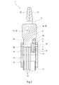
- FIG. 1A and 1B are perspective views of a distal end portion of a robot forceps in which first to third rotary actuators according to an embodiment of the present invention are incorporated.
- FIG. 1A shows a state in which a nail is closed, and FIG. Indicates an open state.
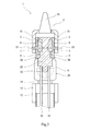
- FIG. 2 is a sectional view taken along the line II-II of FIG. 1.
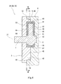
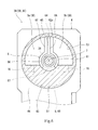
- FIG. 3 is a cross-sectional view along the line III-III in FIG. 1. It is sectional drawing of a 1st rotary actuator.
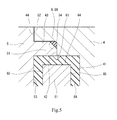
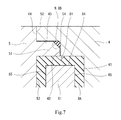
- FIG. 5 is an enlarged view of a main part of FIG. 4.
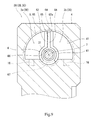
- FIG. 6 is a sectional view taken along the line VI-VI of FIG. 4. It is sectional drawing which expanded the principal part of the rotary actuator of the modification. It is sectional drawing of the rotary actuator of another modification.
- FIG. 9 is a sectional view taken along line IX-IX in FIG. 8.
- FIGS. 1A and 1B show a distal end portion of a robot forceps 1 in which first to third rotary actuators 3A to 3C according to an embodiment of the present invention are incorporated.
- the robot forceps 1 is used, for example, in a surgery support system.
- the doctor remotely controls the robot forceps 1 attached to the slave device by using the master device.
- the robot forceps 1 includes an insertion tube 11 inserted into a patient's body, and a gripper 2 provided at a distal end of the insertion tube 11.
- the insertion tube 11 may be a high-rigidity tube extending linearly, or may be a flexible tube.
- the gripper 2 includes a pair of claws (a first claw 21 and a second claw 22) facing each other, a first rotary actuator 3 ⁇ / b> A for swinging the first claw 21, and a second rotary actuator for swinging the second claw 22. 3B. Furthermore, the robot forceps 1 includes a third rotary actuator 3C that swings the gripper 2 with respect to the insertion tube 11.
- Each of the first to third rotary actuators 3A to 3C is driven by a working fluid.
- the working fluid is a liquid such as physiological saline or oil.
- a drive unit is provided at the root of the insertion tube 11 (on the side opposite to the gripper 2).
- the drive unit supplies and supplies the working fluid to the first to third rotary actuators 3A to 3C.
- a supply / discharge device for discharging is provided.
- the supply of the working fluid from the supply / discharge device (not shown) to the first to third rotary actuators 3A to 3C and the discharge of the working fluid from the first to third rotary actuators 3A to 3C to the supply / discharge device are performed in the insertion pipe 11. This is performed through a plurality of tubes 15 inserted through.
- the rotation axis 31 of the first rotary actuator 3A and the rotation axis 32 of the second rotary actuator 3B are located coaxially.
- the rotation axis 33 of the third rotary actuator 3C is orthogonal to the rotation axes 31 and 32 of the first rotary actuator 3A and the second rotary actuator 3B.
- the distal end side in the axial direction of the insertion tube 11 is referred to as an upper side, and the root side as a lower side.
- a holding member 12 is fixed to the distal end of the insertion tube 11.
- the holding member 12 is configured to be able to be divided into two halves.
- the holding member 12 includes a tubular portion 13 into which the insertion tube 11 is fitted, and a pair of support pieces 14 projecting upward from the tubular portion 13 and facing each other.
- the base 25 of the gripper 2 and the third rotary actuator 3C are arranged between the pair of support pieces 14.
- each of the first to third rotary actuators 3A to 3C has a housing 4 having an internal space 41 in which the vane 6 is arranged, and is attached to the housing 4 to cover the internal space 41.
- the housing 4 and the cover 5 have a substantially rectangular shape when viewed from the axial direction of the rotary actuator (the direction in which the rotation axis extends).
- the shape of the cover 5 may be another shape such as a circular shape.
- the housing 4 of the first rotary actuator 3A, the housing 4 of the second rotary actuator 3B, the base 25, and the housing 4 of the third rotary actuator 3C are integrated into a single block.
- at least one of the housing 4 of the first rotary actuator 3A, the housing 4 of the second rotary actuator 3B, the base 25, and the housing 4 of the third rotary actuator 3C may be separate.
- the vane 6 is integrally provided with a rotary shaft 7 penetrating the cover 5.
- the rotary shaft 7 of the first rotary actuator 3A is non-rotatably connected to the first pawl 21, and the rotary shaft 7 of the second rotary actuator 3B is non-rotatably connected to the second pawl 22.
- the rotary shaft 7 of the third rotary actuator 3C is non-rotatably connected to one support piece 14. That is, in the present embodiment, the housing 4 and the cover 5 of the third rotary actuator 3C rotate relative to the support piece 14.
- the positional relationship between the housing 4 of the third rotary actuator 3C and the cover 5 is reversed from that in FIG. 2, the housing 4 of the third rotary actuator 3C is fixed to the support piece 14, and the rotary shaft 7 cannot rotate with the base 25. May be combined.
- the shapes of the housing 4 and the cover 5 when viewed from the axial direction of the rotary actuator are, for example, circular.
- the rotation shaft 26 is provided on the base 25 coaxially with the rotation shaft 7 of the third rotary actuator 3C.
- the rotary shaft 26 is rotatably supported by the support piece 14 opposite to the support piece 14 to which the rotary shaft 7 of the third rotary actuator 3C is coupled.
- the above-described tube 15 is connected to the base 25. Inside the block composed of the base 25 and the housing 4 of the first to third rotary actuators 3A to 3C, a plurality of flow paths 16 (see FIG. 6, FIGS. 2 and 3) from each tube 15 to the corresponding internal space 41 are provided. Are omitted).
- the first to third rotary actuators 3A to 3C have the same structure as each other. Therefore, the structure of the first rotary actuator 3A will be described in detail below with reference to FIGS.
- the internal space 41 of the housing 4 when viewed from the axial direction of the first rotary actuator 3A, has a substantially semicircular shape so that the vane 6 can swing within an angle range of 180 degrees.
- the shape of the internal space 41 of the housing 4 when viewed from the axial direction of the first rotary actuator 3A may be a fan shape so that the vane 6 can swing within an angle range smaller than 180 degrees.
- a shape in which a part of a circle is missing so that the vane 6 can swing within an angle range larger than 180 degrees may be used.
- the depth of the internal space 41 of the housing 4 is set to about half the height of the vane 6.
- the depth of the internal space 41 can be set arbitrarily as long as it is smaller than the height of the vane 6.
- the housing 4 includes a reference surface 42 located around the internal space 41, an annular wall surface 43 rising from the outer peripheral edge of the reference surface 42, and a top surface 44 located around the wall surface 43.
- the outer contour of the reference surface 42 has a circular shape with the rotation axis 31 as the center.
- the wall surface 43 has a circular cylindrical shape.
- the outer contour of the reference surface 42 may be substantially D-shaped such that the inner space 41 is enlarged.
- the cover 5 includes a protruding portion 51 that fits inside the wall surface 43 and a retreating surface 52 located around the protruding portion 51.
- the distal end surface of the protruding portion 51 contacts the reference surface 42 of the housing 4.
- the outer peripheral surface of the protruding portion 51 faces the wall surface 43 of the housing 4 with a slight gap therebetween, and the receding surface 52 faces the top surface 44 of the housing 4 with a slight gap therebetween.
- the protruding portion 51 is formed with a concave portion 53 that forms the vane accommodating space 30 together with the internal space 41 of the housing 4. That is, the sum of the depth of the concave portion 53 and the depth of the internal space 41 is substantially equal to the height between the side surfaces of the vane 6.
- the vane 6 partitions the vane housing space 30 into a first pressure chamber 3a and a second pressure chamber 3b.
- the distal end surface of the projecting portion 51 of the cover 5 abuts on the reference surface 42 of the housing 4, but the undulation and surface roughness of the distal end surface of the projecting portion 51 and the reference surface 42 of the housing 4. , A leakage path of the working fluid from the vane housing space 30 is formed between the surfaces.
- the retreating surface 52 of the cover 5 may be in contact with the top surface 44 of the housing 4, and the tip surface of the protrusion 51 may be opposed to the reference surface 42 with a slight gap.
- the structure shown in FIG. 5 can reduce the amount of leakage from the vane housing space 30 as compared with the structure shown in FIG.
- the vane 6 includes a cylindrical portion 61 centered on the rotation shaft 31 of the first rotary actuator 3A, and a plate portion 62 protruding radially outward from the outer peripheral surface of the cylindrical portion 61.
- the above-described rotary shaft 7 protrudes from one end surface of the columnar portion 61 and is rotatably supported by the cover 5. Further, a shaft portion 63 is provided on the other end surface of the cylindrical portion 61, and the shaft portion 63 is rotatably supported by the housing 4.
- the inner seal member 8A surrounding the plate portion 62 and the cylindrical portion 61 is attached to the vane 6. More specifically, a linear groove 64 extending in the axial direction of the column portion 61 is formed in the distal end surface 62 a of the plate portion 62, and a columnar surface is formed on the side surface of the plate portion 62 on the cover 5 side and the side surface opposite to the cover 5. A linear groove 65 extending in the radial direction of the portion 61 is formed. Circular grooves 66 are formed on both end surfaces of the cylindrical portion 61, respectively.
- the cylindrical portion 61 has a wide width extending in the axial direction of the cylindrical portion 61 at a position on the outer peripheral surface opposite to the plate portion 62.
- a groove 67 is formed. The inner seal member 8A is inserted into the grooves 64-67.
- the portion of the inner seal member 8A located on the distal end surface 62a of the plate portion 62 (accurately, the portion inserted into the groove 64) has a position corresponding to the reference surface 42 of the housing 4 and the distal end surface of the protrusion 51.
- a notch 81 is formed in the groove.
- the cut 81 traverses a portion of the inner seal member 8A located on the distal end surface 62a of the plate portion 62 in the thickness direction of the plate portion 62.
- the cross section of the cut 81 is triangular, but the cross section of the cut 81 may be, for example, a semicircle or a rectangle.
- an inclined surface 54 that is continuous in the circumferential direction is formed.
- the inclined surface 54 forms an annular seal groove 9 having a triangular cross section between the reference surface 42 of the housing 4 and a corner between the wall surface 43. That is, the seal groove 9 is formed so as to surround the internal space 41 between the housing 4 and the cover 5.
- the outer seal member 8B is inserted into the seal groove 9.
- the outer seal member 8B is, for example, an O-ring having a circular cross-sectional shape in a natural state, as shown by a two-dot chain line in FIG.
- the cross-sectional shape of the outer seal member 8B in the natural state may be another shape such as an elliptical shape.
- the ratio of the cross-sectional area of the outer seal member S2 to the cross-sectional area S1 of the seal groove 9 is preferably 90% or more, and more preferably 95% or more.
- the cross-sectional area S1 of the seal groove 9 is an area of a section surrounded by a line obtained by extending the inclined surface 54 to the reference surface 42 and the wall surface 43 and the reference surface 42 and the wall surface 43.
- the cross-sectional area of the outer seal member S2 is a cross-sectional area in a natural state.
- the seal groove 9 has a triangular cross section
- the outer seal in the seal groove 9 is smaller than the seal groove having a rectangular cross section.
- the filling rate of the member 8B can be increased.
- the outer seal member 8B can be arranged in advance at a corner between the reference surface 42 and the wall surface 43 of the housing 4. Thereby, the cover 5 can be easily attached to the housing 4.
- the cut 81 is formed in a portion of the inner seal member 8A located on the distal end surface 62a of the plate portion 62, the protrusion 51 of the cover 5 is fitted inside the wall surface 43 of the housing 4. When this is done, it is possible to prevent the inner seal member 8A from biting between the reference surface 42 of the housing 4 and the distal end surface of the protrusion 51.
- the depth of the internal space 41 of the housing 4 may be larger than the height of the vane 6, and the protrusion 51 of the cover 5 may fit into the internal space 41.
- the retreating surface 52 of the cover 5 contacts the top surface 44 of the housing 4, and the outer peripheral surface of the protrusion 51 of the cover 5 faces the inner peripheral surface of the internal space 41 with a slight gap.
- an inclined surface 45 that is continuous in the circumferential direction is formed on the inner peripheral edge of the top surface 44 of the housing 4.
- the inclined surface 45 forms an annular seal groove 9 having a triangular cross section between the outer peripheral surface of the protruding portion 51 of the cover 5 and a corner portion between the receding surface 52. That is, the seal groove 9 is formed so as to surround the internal space 41 between the housing 4 and the cover 5.
- the filling rate of the outer seal member 8B in the seal groove 9 can be increased as compared with the seal groove having a rectangular cross section, as in the first embodiment.
- the outer seal member 8 ⁇ / b> B is disposed in advance at a corner between the outer peripheral surface of the projecting portion 51 of the cover 5 and the receding surface 52. Can be. Thereby, the cover 5 can be easily attached to the housing 4.
- the seal groove 9 having a triangular cross section does not necessarily need to be formed using a corner portion between a surface parallel to the radial direction of the rotary actuator and a surface orthogonal to the surface.
- the seal groove having a triangular cross section may be formed using an annular concave portion that is concaved in a V shape from a plane parallel to the radial direction of the rotary actuator.
- the internal space 41 of the housing 4 is open in one direction, but the internal space 41 of the housing 4 is open in both directions.
- Covers 5 may be arranged on both sides.
- the cover 5 may have a recess larger than the internal space 41 of the housing 4 and the housing 4 may be configured to fit into the recess of the cover 5 contrary to FIG. Good.
- the working fluid for driving the rotary actuator of the present invention is not necessarily required to be a liquid, but may be a gas. Further, the rotary actuator of the present invention may be incorporated in various devices other than the robot forceps.
Landscapes
- Engineering & Computer Science (AREA)
- Health & Medical Sciences (AREA)
- Surgery (AREA)
- Life Sciences & Earth Sciences (AREA)
- Mechanical Engineering (AREA)
- Robotics (AREA)
- General Engineering & Computer Science (AREA)
- Animal Behavior & Ethology (AREA)
- Nuclear Medicine, Radiotherapy & Molecular Imaging (AREA)
- Molecular Biology (AREA)
- Heart & Thoracic Surgery (AREA)
- General Health & Medical Sciences (AREA)
- Public Health (AREA)
- Veterinary Medicine (AREA)
- Medical Informatics (AREA)
- Biomedical Technology (AREA)
- Fluid Mechanics (AREA)
- Physics & Mathematics (AREA)
- Ophthalmology & Optometry (AREA)
- Actuator (AREA)
- Surgical Instruments (AREA)
Abstract
L'invention concerne un actionneur rotatif pourvu : d'un boîtier, doté d'un espace interne dans lequel est disposée une aube ; et d'un couvercle, qui est monté sur le boîtier de façon à couvrir l'espace intérieur, une rainure annulaire d'étanchéité, présentant une section transversale triangulaire, étant formée entre le boîtier et le couvercle, de manière à encercler l'espace intérieur, et la rainure d'étanchéité comportant un élément externe d'étanchéité qui y est inséré.
Priority Applications (2)
| Application Number | Priority Date | Filing Date | Title |
|---|---|---|---|
| US17/256,479 US20210128259A1 (en) | 2018-06-26 | 2019-05-28 | Rotary actuator and robotic forceps |
| EP19827077.9A EP3816456A4 (fr) | 2018-06-26 | 2019-05-28 | Actionneur rotatif et forceps robotique |
Applications Claiming Priority (2)
| Application Number | Priority Date | Filing Date | Title |
|---|---|---|---|
| JP2018120498A JP2020002966A (ja) | 2018-06-26 | 2018-06-26 | ロータリアクチュエータおよびロボット鉗子 |
| JP2018-120498 | 2018-06-26 |
Publications (1)
| Publication Number | Publication Date |
|---|---|
| WO2020003853A1 true WO2020003853A1 (fr) | 2020-01-02 |
Family
ID=68984845
Family Applications (1)
| Application Number | Title | Priority Date | Filing Date |
|---|---|---|---|
| PCT/JP2019/020996 Ceased WO2020003853A1 (fr) | 2018-06-26 | 2019-05-28 | Actionneur rotatif et forceps robotique |
Country Status (4)
| Country | Link |
|---|---|
| US (1) | US20210128259A1 (fr) |
| EP (1) | EP3816456A4 (fr) |
| JP (1) | JP2020002966A (fr) |
| WO (1) | WO2020003853A1 (fr) |
Citations (9)
| Publication number | Priority date | Publication date | Assignee | Title |
|---|---|---|---|---|
| US3030934A (en) * | 1958-06-17 | 1962-04-24 | Bogue Elec Mfg Co | Hydraulic actuator |
| JPS524996U (fr) * | 1975-06-26 | 1977-01-13 | ||
| JPS55140104U (fr) * | 1979-03-26 | 1980-10-06 | ||
| EP0283380A2 (fr) * | 1987-03-18 | 1988-09-21 | Societe Europeenne De Propulsion | Dispositif fluidique à palette rotative sans joint d'étanchéité interne |
| JP2006116194A (ja) * | 2004-10-25 | 2006-05-11 | Hitachi Ltd | 手術器具 |
| JP2006223872A (ja) * | 2005-02-18 | 2006-08-31 | Ethicon Endo Surgery Inc | 流体移送制御式関節運動機構を有する外科用器械 |
| JP2008100350A (ja) * | 2005-03-29 | 2008-05-01 | Toshiba Corp | マニピュレータ |
| JP2011185431A (ja) | 2010-03-08 | 2011-09-22 | Pubot Giken:Kk | 広角度ベーン形揺動アクチュエータ |
| US20150127045A1 (en) * | 2012-07-17 | 2015-05-07 | Richard Wolf Gmbh | Endoscopic instrument |
Family Cites Families (8)
| Publication number | Priority date | Publication date | Assignee | Title |
|---|---|---|---|---|
| GB663821A (en) * | 1946-06-19 | 1951-12-27 | United Aircraft Corp | Improvements in or relating to vane motors |
| GB958841A (en) * | 1961-06-23 | 1964-05-27 | Bouge Electric Mfg Co | Improvements in or relating to hydraulically actuated devices |
| DE3776972D1 (de) * | 1986-06-09 | 1992-04-09 | Allied Signal Inc | Hydraulisches schwenkfluegelstellglied. |
| DE102012025101A1 (de) * | 2012-12-20 | 2014-06-26 | avateramedical GmBH | Aktive Positioniereinrichtung eines chirurgischen Instruments und ein diese umfassendes chirurgisches Robotersystem |
| DE102014204568B4 (de) * | 2014-03-12 | 2019-05-23 | Fraunhofer-Gesellschaft zur Förderung der angewandten Forschung e.V. | Chirurgisches Instrument |
| CN106572889B (zh) * | 2014-08-13 | 2019-09-06 | 柯惠Lp公司 | 机器人控制的具有机械优势的夹持 |
| DE102014217796B4 (de) * | 2014-09-05 | 2025-07-17 | Richard Wolf Gmbh | Instrument, insbesondere medizinisch-endoskopisches Instrument oder Technoskop |
| JP6646570B2 (ja) * | 2016-12-28 | 2020-02-14 | 川崎重工業株式会社 | ロボット鉗子 |
-
2018
- 2018-06-26 JP JP2018120498A patent/JP2020002966A/ja active Pending
-
2019
- 2019-05-28 WO PCT/JP2019/020996 patent/WO2020003853A1/fr not_active Ceased
- 2019-05-28 EP EP19827077.9A patent/EP3816456A4/fr not_active Withdrawn
- 2019-05-28 US US17/256,479 patent/US20210128259A1/en not_active Abandoned
Patent Citations (9)
| Publication number | Priority date | Publication date | Assignee | Title |
|---|---|---|---|---|
| US3030934A (en) * | 1958-06-17 | 1962-04-24 | Bogue Elec Mfg Co | Hydraulic actuator |
| JPS524996U (fr) * | 1975-06-26 | 1977-01-13 | ||
| JPS55140104U (fr) * | 1979-03-26 | 1980-10-06 | ||
| EP0283380A2 (fr) * | 1987-03-18 | 1988-09-21 | Societe Europeenne De Propulsion | Dispositif fluidique à palette rotative sans joint d'étanchéité interne |
| JP2006116194A (ja) * | 2004-10-25 | 2006-05-11 | Hitachi Ltd | 手術器具 |
| JP2006223872A (ja) * | 2005-02-18 | 2006-08-31 | Ethicon Endo Surgery Inc | 流体移送制御式関節運動機構を有する外科用器械 |
| JP2008100350A (ja) * | 2005-03-29 | 2008-05-01 | Toshiba Corp | マニピュレータ |
| JP2011185431A (ja) | 2010-03-08 | 2011-09-22 | Pubot Giken:Kk | 広角度ベーン形揺動アクチュエータ |
| US20150127045A1 (en) * | 2012-07-17 | 2015-05-07 | Richard Wolf Gmbh | Endoscopic instrument |
Non-Patent Citations (1)
| Title |
|---|
| See also references of EP3816456A4 |
Also Published As
| Publication number | Publication date |
|---|---|
| JP2020002966A (ja) | 2020-01-09 |
| EP3816456A1 (fr) | 2021-05-05 |
| EP3816456A4 (fr) | 2022-03-09 |
| US20210128259A1 (en) | 2021-05-06 |
Similar Documents
| Publication | Publication Date | Title |
|---|---|---|
| US4219618A (en) | Dental hand tool holder | |
| JP2024081697A5 (fr) | ||
| ES2864884T3 (es) | Conector sin aguja con válvula flexible | |
| JP2009028156A5 (fr) | ||
| TW201407071A (zh) | 流量控制裝置 | |
| JP6594526B2 (ja) | 内視鏡 | |
| JP2010236424A (ja) | ロータ駆動機構及びそれを備えるポンプ装置 | |
| BRPI0808083A2 (pt) | Membro de alojamento e conjunto para um instrumento cirúrgico motorizado, e, método para acionar um instrumento cirúrgico. | |
| JP2019527111A5 (fr) | ||
| WO2020003853A1 (fr) | Actionneur rotatif et forceps robotique | |
| JP5798250B2 (ja) | ギヤポンプ | |
| US20160201660A1 (en) | A fluid cylinder | |
| CN214484649U (zh) | 牙科弯手机机头组件和牙科弯手机 | |
| BRPI0805749A2 (pt) | aperfeiÇoamento em vedaÇço de trocater | |
| CN109996503A (zh) | 机器人钳子 | |
| TWI827307B (zh) | 單軸偏心螺桿泵 | |
| JP6647848B2 (ja) | ベーンポンプ装置 | |
| CN112618057A (zh) | 牙科弯手机机头组件和牙科弯手机 | |
| JP2005308097A (ja) | 開閉バルブ及び真空チャンバの開口部の開閉方法 | |
| WO2017047484A1 (fr) | Pompe à palettes à cartouche | |
| JP2007077805A (ja) | ポンプのロータ装置 | |
| JP4824597B2 (ja) | 関節機構 | |
| US20220265375A1 (en) | Instrument for a robotic surgery system | |
| BR112020023256A2 (pt) | junta de tubo | |
| JP2020020429A5 (fr) |
Legal Events
| Date | Code | Title | Description |
|---|---|---|---|
| 121 | Ep: the epo has been informed by wipo that ep was designated in this application |
Ref document number: 19827077 Country of ref document: EP Kind code of ref document: A1 |
|
| NENP | Non-entry into the national phase |
Ref country code: DE |
|
| ENP | Entry into the national phase |
Ref document number: 2019827077 Country of ref document: EP Effective date: 20210126 |