WO2020003874A1 - Sonde d'estimation de quantité d'urine et dispositif d'estimation de quantité d'urine l'utilisant - Google Patents
Sonde d'estimation de quantité d'urine et dispositif d'estimation de quantité d'urine l'utilisant Download PDFInfo
- Publication number
- WO2020003874A1 WO2020003874A1 PCT/JP2019/021455 JP2019021455W WO2020003874A1 WO 2020003874 A1 WO2020003874 A1 WO 2020003874A1 JP 2019021455 W JP2019021455 W JP 2019021455W WO 2020003874 A1 WO2020003874 A1 WO 2020003874A1
- Authority
- WO
- WIPO (PCT)
- Prior art keywords
- probe
- urine volume
- sensor
- bladder
- unit
- Prior art date
- Legal status (The legal status is an assumption and is not a legal conclusion. Google has not performed a legal analysis and makes no representation as to the accuracy of the status listed.)
- Ceased
Links
Images


Classifications
-
- A—HUMAN NECESSITIES
- A61—MEDICAL OR VETERINARY SCIENCE; HYGIENE
- A61B—DIAGNOSIS; SURGERY; IDENTIFICATION
- A61B8/00—Diagnosis using ultrasonic, sonic or infrasonic waves
- A61B8/08—Clinical applications
Definitions
- the present technology relates to a urine volume estimation probe that detects the shape of the bladder using ultrasonic waves, and a urine volume estimation device that estimates the urine volume using the probe.
- Patent Literature 1 discloses an ultrasonic urine volume sensor in which a plurality of ultrasonic oscillation elements that oscillate ultrasonic waves toward a bladder wall surface are arranged along a bladder extending direction (substantially up and down direction). . Further, in Patent Document 2, an arrangement is set such that a plurality of sensors using ultrasonic transducers can detect the shape of the bladder and an ultrasonic emission angle. For example, the number of sensors emitted to the bottom of the bladder is maximized, A non-invasive urine volume estimation sensor unit is disclosed that is arranged to have a plurality of sensor rows from the top to the top.
- the probe should not be applied to the body every time urine volume is measured. It is preferable that it is always worn and that the amount of urine can be automatically estimated at regular intervals.
- the urine volume estimation probe in order to accurately estimate the urine volume in the bladder, it is important to attach the urine volume estimation probe to an appropriate position on the body.
- a method of confirming the position of the pubic bone by the subject himself, predicting the position of the bladder based on the position, and mounting the bladder is adopted. In some cases, the accuracy of urine volume estimation was reduced.
- An object of the present invention is to provide an estimation probe and a urine volume estimation device using the same.
- the present inventor arranges a plurality of sensors of the probe not in the height direction but in the width direction (substantially the left-right direction), and provides a sensor below the sensor for determining the mounting position of the probe. They found that the problem could be solved, and completed this technology.
- the present technology is a probe having a plurality of sensors that transmit ultrasonic waves into a body and detect reflected waves of the ultrasonic waves, wherein the probe has a first sensor unit and the first sensor unit.
- a second sensor unit disposed below the sensor unit, wherein the first sensor unit has at least two of the plurality of sensors arranged in the width direction of the probe.
- the second sensor section has a configuration in which at least one sensor of the plurality of sensors is disposed below the first sensor section, and wherein the second sensor section has A probe for estimating urine volume is provided, which includes a positioning sensor for determining a mounting position of the probe on a body.
- the present invention also provides a urine volume estimation device including the urine volume estimation probe and a main unit connected to the probe via a cable.
- the senor by disposing the sensor in the width direction of the probe, it is more compact in the height direction than the conventional probe, so that discomfort during mounting is less, and the patient is in a supine position, a sitting position, etc.
- the urine volume can be estimated efficiently regardless of the posture.
- a positioning sensor for determining the mounting position of the probe positioning before mounting can be easily performed.
- FIG. 1 is a schematic side view of a probe for estimating urine volume according to an example of an embodiment of the present technology. It is a schematic diagram of a urine volume estimation device according to an example of an embodiment of the present technology. 1 is a block diagram of a urine volume estimation device according to an example of an embodiment of the present technology. 1 is a schematic diagram of a urine volume estimation system according to an example of an embodiment of the present technology. It is a flowchart regarding the positioning of the probe for urine volume estimation according to an example of an embodiment of the present technology.
- FIG. 2 is a first schematic diagram relating to positioning of a urine volume estimation probe according to an example of an embodiment of the present technology.
- FIG. 6 is a second schematic diagram relating to positioning of a urine volume estimation probe according to an example of an embodiment of the present technology.
- FIG. 13 is a third schematic diagram related to positioning of a urine volume estimation probe according to an example of an embodiment of the present technology. It is an example of the reflected wave detected by the urine volume estimation probe according to an example of an embodiment of the present technology. It is an example of the reflected wave detected by the urine volume estimation probe according to an example of an embodiment of the present technology. It is an example of the reflected wave detected by the urine volume estimation probe according to an example of an embodiment of the present technology. It is an example of a screen of a user terminal regarding positioning of a urine volume estimation probe concerning an example of an embodiment of the present technology.
- FIG. 1 is a first schematic diagram relating to a urine volume estimation method according to an example of an embodiment of the present technology.
- FIG. 11 is a second schematic diagram related to a urine volume estimation method according to an example of an embodiment of the present technology.
- FIG. 13 is a third schematic diagram illustrating a urine volume estimation method according to an example of an embodiment of the present technology.
- the probe for estimating urine volume according to the present technology has a plurality of sensors that transmit ultrasonic waves into the body and detect reflected waves of the ultrasonic waves, and based on information of the reflected waves detected by each sensor. Is used to estimate the amount of urine in the bladder.
- the target for estimating the amount of urine is not particularly limited, and is, for example, a patient suffering from urination disorder or urinary incontinence, or an elderly person having difficulty in going to the toilet by himself.
- the probe for estimating urine volume according to the present technology is arranged on the skin of the abdomen of such a subject and at a position corresponding to the bladder (for example, the lower abdomen), and is fixed to the body with a tape or a belt. You. A gel or the like is applied between the probe for estimating urine volume and the abdomen to improve the permeability of the ultrasound to the abdomen.
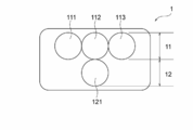
- FIG. 1 is a schematic diagram of a urine volume estimation probe according to an example of an embodiment of the present technology.
- the probe for estimating urine amount 1 according to the present embodiment has a substantially rectangular shape with a rounded corner and a plurality of sensors 111, 112, 113, 121.
- the urine volume estimation probe 1 includes at least a first sensor unit 11 and a second sensor unit 12 disposed below the first sensor unit 11.
- the first sensor unit 11 has a configuration in which at least two sensors are arranged in the width direction of the probe 1.
- the first sensor unit 11 may have a configuration in which, for example, a first sensor 111, a second sensor 112, and a third sensor 113 are arranged in the width direction of the probe 1 in a front view.
- the second sensor unit 12 has a configuration in which at least one sensor is disposed below the first sensor unit 11.
- the second sensor unit 12 may have a configuration in which, for example, the fourth sensor 121 is disposed below the first sensor unit 11.
- the vertical direction of the probe 1 is the vertical direction when the subject wears the probe 1. That is, the second sensor unit 12 is located below the first sensor unit 11 when the subject wears the probe 1.
- the second sensor section 12 includes a positioning sensor for determining the mounting position of the probe 1 on the body.
- one sensor for example, the fourth sensor 121
- the second sensor unit 12 has two or more sensors, all the sensors constituting the second sensor unit 12 may be used for both the urine volume estimation and the positioning of the probe 1.
- the second sensor unit 12 may have a configuration in which a urine volume estimation sensor and a positioning sensor are separately provided.
- the sensors 111, 112, 113, and 121 each have a piezoelectric element and transmit and receive ultrasonic waves. Specifically, when electrodes are formed on both sides of the piezoelectric element and a voltage is applied between the two electrodes, the piezoelectric element vibrates according to the drive voltage to transmit ultrasonic waves, while receiving ultrasonic waves, It is configured to generate an electric signal according to the vibration.
- the shape of each sensor is not particularly limited, but may be, for example, a circular thin plate, a square, or a rectangle.
- FIG. 2 is a schematic side view of the urine volume estimation probe according to the present embodiment.
- sensor 111,112,113,121 according to the present embodiment is arranged at a predetermined angle ⁇ relative to the axis l 11 or l 12 perpendicular to the array surface l 10 of each sensor, respectively, Ultrasound is transmitted into the body at each angle ⁇ .
- the first sensor 111, the second sensor 112, and the third sensor 113 are arranged so as to transmit ultrasonic waves 1111, 1121, and 1311 in a radial direction in a direction (height direction) in which the bladder expands.
- the ultrasonic transmission angles ⁇ 111 , ⁇ 112 (omitted in FIG. 2 because they are 0 degrees) and ⁇ 113 are different from each other.
- the ultrasonic transmission angles ⁇ 111 , ⁇ 112 , and ⁇ 113 are preferably in the range of ⁇ 40 to +40 degrees when the direction above the axis l 11 is a positive direction.
- the fourth sensor 121 is preferably disposed so as to transmit ultrasonic waves 1211 downward with respect to the axis l 12 perpendicular to the array surface l 10 of the sensor. By configuring so that the ultrasonic wave 1211 is transmitted downward, the probe 1 can transmit the ultrasonic wave from the lower end of the bladder to a position closer to the upper end, and the urine volume can be measured more accurately. .
- the ultrasonic transmission angle ⁇ 121 of the fourth sensor 121 is preferably arranged in a range of ⁇ 40 to 0 degrees when the upper side of the axis l 12 is set to a positive direction.
- the ultrasonic transmission angle ⁇ 121 of the fourth sensor 121 constituting the second sensor unit 12 is determined by the ultrasonic wave of the first sensor 111, the second sensor 112, and the third sensor 113 constituting the first sensor unit 11. It is preferable that the transmission angles ⁇ 111 , ⁇ 112 , and ⁇ 113 be negatively larger than the transmission angles ⁇ 111 , ⁇ 112 , and ⁇ 113 .
- the fourth sensor 121 reliably detects the lower end of the bladder or the upper edge of the pubic bone, and the first sensor 111, the second sensor 112, and the third sensor 113 reach the upper end of the bladder. Information can be obtained efficiently.
- the sensors constituting the first sensor unit 11 may be arranged in a line in the width direction, but are arranged with their positions shifted in the height direction. It may be.
- the urine volume estimating apparatus is based on the information obtained from the urine volume estimating probe, and informs information related to the position of the probe and information related to urine volume in the bladder. Used for Hereinafter, this will be described in more detail with reference to FIGS.
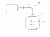
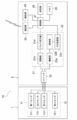
- FIG. 3 shows a schematic diagram of a urine volume estimation device according to an example of an embodiment of the present technology.
- the urine volume estimation device 10 includes a urine volume estimation probe 1 and a main unit 2 connected to the probe 1 by a cable 3.
- the cable 3 according to the present embodiment is preferably extended from the side surface in the width direction of the probe 1 in a front view. By extending the cable 3 not in the height direction but in the width direction of the probe 1, the cable 3 is less likely to hinder the movement of the subject's body, and discomfort during wearing can be further reduced.
- the main unit 2 according to the present embodiment is mounted on, for example, the clothes of the subject.
- the main body unit 2 includes a transmitting unit 21 that outputs a driving voltage to the first sensor unit 11 and the second sensor unit 12, a receiving unit 22 that receives an electric signal from the sensor, and a transmitting unit.
- a switch 23 for switching sensors connected to the reception unit 21 and the reception unit 22, a notification unit 24 for notifying various information to the outside, a communication unit 25 for communicating with the outside, and a storage unit 26 for storing various data
- a control unit 27 that performs overall control of the main body unit 2 and a memory 28 that stores various parameters.
- the transmission unit 21 supplies a drive voltage to the first sensor unit 11 and the second sensor unit 12.
- the transmission section 21 has a pulse generator 21a and an amplification section 21b.
- the pulse generator 21a generates a pulse signal having a predetermined pulse width and a predetermined voltage value.
- the pulse generator 21a may be configured so that the pulse width, the number of pulses, and the frequency can be changed.
- the amplifying unit 21b amplifies the pulse signal from the pulse generator 21a and outputs it as a drive voltage to the first sensor unit 11 and the second sensor unit 12.
- the receiving unit 22 receives electric signals from the first sensor unit 11 and the second sensor unit 12.
- the receiving unit 22 has an amplifying unit 22a, a detecting unit 22b, and an A / D converting unit 22c.
- the amplification unit 22a amplifies signals received from the first sensor unit 11 and the second sensor unit 12, and outputs the signals to the detection unit 22b.
- the detector 22b demodulates the received signal (for example, an amplitude modulated wave) received from the amplifier 22a by a method such as envelope detection and outputs the processed signal to the A / D converter 22c.
- the A / D converter 22c performs A / D conversion on the received signal from the detector 22b and outputs the signal to the controller 27.
- the switch 23 selects a sensor connected to the transmitting unit 21 and the receiving unit 22 from among the sensors constituting the first sensor unit 11 and the second sensor unit 12. For example, in the case of the mode for positioning the urine volume estimation probe, only the positioning sensor of the second sensor unit 12 is selected. In the case of the mode for estimating the urine volume and notifying the urination timing, the mode is selectively switched from the first sensor unit 11 and the second sensor unit 12.
- the notification unit 24 is, for example, a vibrator, an LED lamp, an alarm, or the like.
- the notification unit 24 is an LED lamp
- the notification unit 24 may be provided in the main body unit 2 as shown in FIG.
- the subject is notified of various information (for example, the position of the probe 1 with respect to the bladder, the arrival of urination timing, and the like) by the vibration of the vibrator, the lighting mode of the LED lamp, the sound, and the like.
- the communication unit 25 communicates with an external communication device.
- the communication unit 25 performs communication according to the Bluetooth (registered trademark) standard.
- the communication unit 25 communicates with the user terminal 4 in the urine volume estimation system 100 described later.
- the storage unit 26 temporarily stores the reception signal received from the reception unit 22.
- the storage unit 26 also stores information acquired from the user terminal 4 via the communication unit 25 in the urine volume estimation system 100 described below.
- the control unit 27 has one or a plurality of processors, and controls the transmission unit 21, the reception unit 22, the switch 23, the notification unit 24, and the communication unit 25.
- control unit 27 controls the switch 23 to switch the sensors connected to the transmission unit 21 and the reception unit 22.
- the control unit 27 controls the transmission unit 21 to output a drive voltage to the first sensor unit 11 and the second sensor unit 12.
- control unit 27 controls the receiving unit 22 to convert the received signals of the first sensor unit 11 and the second sensor unit 12 into digital signals, and performs averaging processing on the received signals from the receiving unit 22. Is performed.
- the control unit 27 determines the position of the probe 1 with respect to the bladder, the amount of urine in the bladder, the arrival of urination timing, and the like based on the reception signal from the reception unit 22, and performs processing according to the analysis result. (For example, the notification unit 24 is operated).
- control unit 27 controls the communication unit 25 to transmit information on a signal received from the reception unit 22 to the outside. Further, the control unit 27 receives a signal from the outside via the communication unit 25 and performs a process according to the signal (for example, activates the notification unit 24).
- the memory 28 stores parameters such as the frequency, output, number of pulses, gain (amplification factor), and standby time of the ultrasonic wave.
- the probe 1 for estimating urine volume and the main unit 2 may be wirelessly connected without being connected by wire.
- FIG. 5 is a schematic diagram of a urine volume estimation system according to an example of an embodiment of the present technology.
- the urine volume estimation system 100 includes the above-described urine volume estimation device 10, a user terminal 4 that receives a signal transmitted from the urine volume estimation device 10 and provides an application or the like, and mainly as a database. And a functioning server 5.
- the urine volume estimation device 10 performs wireless communication with the user terminal 4, and the user terminal 4 performs wireless communication with the server 5.
- the user terminal 4 can be, for example, a smartphone or a tablet terminal. By registering the urine volume estimation device 10 in the user terminal 4 in advance, communication between the urine volume estimation device 10 and the user terminal 4 becomes possible.
- the number of the user terminals 4 is not limited to one, but may be a plurality (for example, a caregiver user terminal 4 and a target person user terminal 4).
- the user terminal 4 estimates the amount of urine in the bladder and determines the timing of urination based on the reception signal transmitted from the urine amount estimation device 10.
- the user terminal 4 includes information on the target person such as a user ID for specifying the target person and a device ID for specifying the urine volume estimation device 10; information on a reception signal transmitted from the urine volume estimation device 10; urine volume in the bladder And data and the like for estimating the urine and determining the urination timing; analysis results relating to urine volume in the bladder, urination timing, and the like;
- the user terminal 4 downloads an application dedicated to the urine volume estimation system 100, thereby notifying the user of information such as the urine volume in the subject's bladder and urination timing, and transmitting / receiving information to / from the server 5. Or you can go.
- the server 5 performs so-called cloud computing.
- the server 5 can communicate with the user terminal 4 by registering the user terminal 4 in advance, and information of the user terminal 4 is stored in association with the urine volume estimation device 10.
- a dedicated application is downloaded to the user terminal 4, information is transmitted and received between the user terminal 4 and the server 5, for example, once a day.
- the server 5 includes information on the target such as a user ID for specifying the target, a device ID for specifying the urine volume estimation device 10, and a terminal ID for specifying the user terminal 4; urine in the bladder transmitted from the user terminal 4. Analysis result data relating to the amount, urination timing, and the like are stored. Further, it is possible to machine-learn a threshold value for judging the urination timing of the target person and information on the timing of notifying the urination timing.
- the urine volume estimation device is configured to position the urine volume estimation probe with respect to the bladder based on information of the reflected wave detected by the above-described positioning sensor. And the positioning can be performed so that the probe is mounted at an appropriate position.
- an operation example of the urine volume estimation system when positioning the urine volume estimation probe will be described with reference to FIG.
- the fourth sensor 121 of the second sensor unit 12 is used for both of the urine volume estimation and the positioning of the probe 1 is shown, but a positioning sensor separate from the fourth sensor 121 is used. Is provided, the fourth sensor 121 may be replaced with the positioning sensor in the following description.
- the control unit 27 outputs an ultrasonic wave transmission command (step S11). Specifically, the control unit 27 controls the switch 23 so that the fourth sensor 121 is connected to the transmission unit 21 and the reception unit 22, and outputs a pulse signal generation command to the transmission unit 21.
- the generation command serves as a trigger for positioning the urine volume estimation probe 1, and the transmission unit 21 supplies a driving voltage based on the generation command to the fourth sensor 121.
- the fourth sensor 121 transmits an ultrasonic wave based on the drive voltage.
- the control unit 27 outputs the generation command at a predetermined cycle.
- Step S12 when the fourth sensor 121 receives the ultrasonic wave (Step S12), the receiving unit 22 processes the received signal.
- the control unit 27 determines whether the received signal includes a reflected wave from the bladder (Step S13).
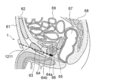
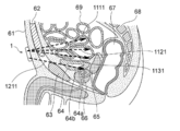
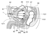
- FIGS. 7 to 9 are schematic sectional views of the lower abdomen of the human body.
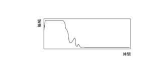
- FIGS. 10 to 12 show examples of the detected reflected wave.
- the small intestine 69 is located above the bladder 64, and the pubic bone 63 is located diagonally below and in front of the bladder 64.
- the probe 1 When determining the mounting position of the urine volume estimation probe 1, the probe 1 is gradually applied from above the abdomen. As shown in FIG. 7, when the ultrasonic wave 1211 transmitted from the fourth sensor 121 of the probe 1 reaches the small intestine 69 and does not reach the bladder 64, a reflected wave as shown in FIG. Is detected.
- the probe 1 is slightly moved downward. Then, the ultrasonic wave 1211 reaches the bladder 64, and as shown in FIG. 11, a reflected wave W from the back wall 64a of the bladder 64 (hereinafter, also referred to as a "reflected wave W from the bladder 64") is detected. Will be done.
- the ultrasonic wave 1211 is transmitted below the bladder 64, and the reflected wave W from the bladder 64 can be detected as shown in FIG. Disappears.
- the urine volume estimation probe 1 can be positioned based on the presence or absence of the reflected wave W from the bladder 64.
- the control unit 27 determines that the bladder 64 has been detected when the reflected wave W from the bladder 64 is included in the reception signal of the fourth sensor 121. For example, the LED lamp of the notification unit 24 lights up in green. Then, a command is output to the notifying unit 24 (step S141). On the other hand, when the reflected wave W from the bladder 64 is not included in the received signal, it is determined that the bladder 64 has not been detected, and, for example, the notification unit 24 is turned on so that the LED lamp of the notification unit 24 lights red. A command is output (step S142). At this time, not only the notification unit 24 but also the display of the user terminal 4 may be displayed in green or red. Alternatively, the user terminal 4 may present an instruction screen 41 as shown in FIG. 13 to indicate an optimal mounting position of the urine volume estimation probe 1.
- the control unit 27 sets a standby time (steps S151 and S152), and determines whether the standby time has elapsed since the previous transmission of the ultrasonic wave 1211 (steps S161 and S162). If the standby time has elapsed, the control unit 27 outputs an ultrasonic transmission command again (step S11). On the other hand, if the standby time has not elapsed, the control unit 27 waits for the standby time to elapse, and outputs an ultrasonic transmission command again after the standby time has elapsed (step S11). In this way, the control unit 27 issues an ultrasonic transmission command at intervals of the standby time, and periodically determines the position of the urine volume estimation probe 1 with respect to the bladder 64.
- the urine volume estimation device 10 includes the urine volume estimation probe 1 and the main device unit 2, and the fourth sensor of the second sensor unit 12 included in the probe 1. Based on the reflected wave W from the bladder 64 detected by 121, the control unit 27 of the main device 2 determines the position of the probe 1 with respect to the bladder 64. That is, the method for determining the mounting position of the urine volume estimation probe according to the present technology includes the steps of transmitting ultrasonic waves into the body, detecting reflected waves of the ultrasonic waves from the body, and detecting from the reflected waves. Determining the position of the probe with respect to the bladder based on the reflected waves from the bladder.
- control unit 27 may determine the optimal mounting position of the urine volume estimation probe 1 based on the lower end 64b of the bladder 64, The optimal mounting position may be determined based on the upper edge. Further, the optimal mounting position may be determined based on both the lower end of the bladder 64 and the upper edge of the pubic bone 63.
- the urine volume estimation device uses the urine volume in the bladder based on information on reflected waves detected by the first sensor unit and the second sensor unit. Can be estimated and urination timing can be notified.
- an operation example of the urine volume estimation system when estimating the urine volume and notifying the urination timing will be described with reference to FIG.
- the control unit 27 outputs an ultrasonic wave transmission command (step S21). Specifically, the control unit 27 causes the first sensor 111, the second sensor 112, the third sensor 113, and the fourth sensor 121 to transmit and receive ultrasonic waves in order while switching the switch 23.
- the control unit 27 controls the switch 23 so that the first sensor 111 is connected to the transmission unit 21 and the reception unit 22, and outputs a pulse signal generation command to the transmission unit 21.
- the transmitting unit 21 supplies a driving voltage based on the generation command to the first sensor 111, and the first sensor 111 transmits an ultrasonic wave based on the driving voltage.
- the same control is performed for the second sensor 112, the third sensor 113, and the fourth sensor 121.
- the control unit 27 outputs this generation command at a predetermined cycle.
- the receiving unit 22 processes a signal received from each sensor.
- the control unit 27 determines a urine volume level from the received signal and determines whether the urine volume level is equal to or higher than a threshold (step S23).
- the user terminal 4 that has received the information of the received signal via the communication unit 25 may determine the urine volume level.
- the “urine volume level” is a value representing the urine volume in the bladder, and may be, for example, the number of sensors in which the received signal includes the reflected wave W from the bladder 64.
- FIGS. 15 to 17 are schematic sectional views of the lower abdomen of the human body. Note that the structure is common to FIGS. 7 to 9 and will not be described.
- the ultrasonic wave 1211 transmitted from the fourth sensor 121 reaches the bladder 64, and the reflected wave W from the bladder 64 in the fourth sensor 121 is Is detected.
- the ultrasonic waves 1111, 1121, and 1311 transmitted from the first sensor 111, the second sensor 112, and the third sensor 113 do not reach the bladder 64, and are transmitted to the first sensor 111, the second sensor 112, and the third sensor 113.
- the reflected wave W from the bladder 64 is not detected. That is, in FIG. 15, the urine volume level is “1”.
- the bladder 64 expands in the height direction and pushes up the small intestine 69. Then, in addition to the ultrasonic wave 1211 transmitted from the fourth sensor 121, the ultrasonic wave 1131 transmitted from the third sensor 113 also reaches the bladder 64, and is reflected by the third sensor 113 and the fourth sensor 121 from the bladder 64. Wave W is detected. On the other hand, the ultrasonic waves 1111, 1121 transmitted from the first sensor 111 and the second sensor 112 do not reach the bladder 64, and the reflected waves W from the bladder 64 are not detected by the first sensor 111 and the second sensor 112. That is, in FIG. 16, the urine volume level is “2”.
- the bladder 64 further expands in the height direction and pushes up the small intestine 69. Then, the ultrasonic waves 1111, 1121, 1131, and 1211 transmitted from all the sensors from the first sensor 111 to the fourth sensor 121 reach the bladder 64, and the reflected waves W from the bladder 64 are detected by all the sensors. You. That is, in FIG. 17, the urine volume level is “4”.
- the urine volume level increases as the urine volume in the bladder 64 increases, the urine volume can be estimated based on the urine volume level.
- the time-series change in the urine volume level is stored in the storage unit 26 and / or the user terminal 4.
- the control unit 27 or the user terminal 4 determines that the urine volume is small and the urination timing is short. Then, the control unit 27 sets a standby time (step S26). Then, it is determined whether or not the standby time has elapsed since the last transmission of the ultrasonic wave (step S27). If the standby time has elapsed, the control unit 27 outputs an ultrasonic wave transmission command again (step S21). On the other hand, if the standby time has not elapsed, the control unit 27 waits for the standby time to elapse, and outputs an ultrasonic transmission command again after the standby time has elapsed (step S21). In this way, the control unit 27 periodically issues an ultrasonic transmission command until the urine volume level reaches the threshold.
- the control unit 27 or the user terminal 4 determines that the urine volume has reached the threshold value or higher and urination timing is near. Then, the control unit 27 activates, for example, the notification unit 24, and notifies the user terminal 4 of the urination timing via the communication unit 25 (step S24). This allows the user of the user terminal 4 to be notified of the urination timing and to guide the subject to the toilet.
- the control unit 27 waits for a report that actual urination has occurred (step S25).
- the subject, the caregiver, or the like operates the user terminal 4 to input a report indicating that there was actual urination or a time at which urination occurred, and transmit the time to the urine volume estimation device 10.
- the control unit 27 sets a standby time (step S26), and determines whether or not the standby time has elapsed since the previous transmission of the ultrasonic wave (step S27). If the standby time has elapsed, the control unit 27 outputs an ultrasonic wave transmission command again (step S21). On the other hand, if the standby time has not elapsed, the control unit 27 waits for the standby time to elapse, and outputs an ultrasonic transmission command again after the standby time has elapsed (step S21). In this way, the control unit 27 issues an ultrasonic transmission command at intervals of the standby time, and periodically estimates the amount of urine in the bladder 64 and notifies the urination timing.
- the urine volume estimation device 10 includes the urine volume estimation probe 1 and the main body device unit 2, and includes the first sensor unit 11 and the second sensor unit 2 included in the probe 1.
- the control unit 27 of the main unit 2 estimates the amount of urine in the bladder and urinates Notify the timing. That is, the urine volume estimation method according to the present technology includes a step of transmitting an ultrasonic wave into the body, a step of detecting a reflected wave of the ultrasonic wave from the body, and a step of detecting a reflected wave from the bladder detected from the reflected wave.
- the urination timing notification method in addition to the above-described urine volume estimation method, a step of determining whether the number of sensors that have detected reflected waves from the bladder is equal to or greater than a threshold, For notifying the urination timing.
- the control unit 27 and the user terminal 4 determine the presence or absence of the reflected wave W from the bladder 64 based on whether the reflected wave W from the bladder 64 is completely zero. Instead, when the amplitude of the reflected wave W from the bladder 64 detected by each sensor is equal to or greater than a predetermined threshold value, it is determined that the reflected wave W from the bladder 64 is present, and the amplitude of the reflected wave W from the bladder 64 is determined. Is smaller than the predetermined threshold, it may be determined that there is no reflected wave W from the bladder 64.
- control unit 27 and the user terminal 4 send the ultrasonic wave to the highest position in the height direction of the bladder 64 among the sensors in which the reflected wave W from the bladder 64 is detected.
- the reflected wave W from the bladder 64 is detected by the third sensor 113 in FIG. 16, it is considered that the third sensor 113 and the fourth sensor 121 are reacting, and the urine volume level is determined to be “2”. May be.
- FIG. 17 if the reflected wave W from the bladder 64 is detected by the first sensor 111, it is considered that all the sensors from the first sensor 111 to the fourth sensor 121 are responding, and the urine volume level is reduced. It may be determined to be “4”.
- the configuration may be such that the amount of urine in the bladder 64 is estimated from the time difference between the reflected waves of the front wall and the rear wall of the bladder 64 in consideration of the change in the size of the bladder 64 in the depth direction.
- the control unit 27 and the user terminal 4 may be configured to estimate the urine volume in consideration of not only the presence or absence of the reflected wave W from the bladder 64 but also the presence or absence of a reflected wave from the small intestine 69.
- the threshold of the urine volume level may be set by the initial value stored in the memory 26, and the user or the caregiver can freely change the setting at the user terminal 4. You may do so. Further, the time at which the urination timing is notified and the time at which the report indicating that there was actual urination are input are stored in the storage unit 26 and / or the user terminal 4, and the server 5 performs machine learning to set the threshold. The setting may be automatically changed so that a new threshold can be overwritten in the memory 26 at any time.
- the standby time may be set by the initial value stored in the memory 26, and the target person or the caregiver can freely change the setting at the user terminal 4. Is also good. Further, the standby time may be automatically changed as appropriate based on the urine volume in the bladder estimated by the control unit 27, and for example, the standby time may be set to be shorter as the urine volume increases. Alternatively, the time-series change of the urine volume is stored in the storage unit 26 and / or the user terminal 4, and the standby time is automatically changed by machine learning in the server 5, and the new standby time is changed as needed in the memory 26. May be overwritten.
- the present technology can also provide a training method for a patient having a dysuria such as pollakisuria. If there is a habit of immediately going to the toilet without much urine being accumulated in the bladder 64, the instructor 24 or the user terminal 4 puts up urination until the urination timing is notified, so that the number of times of going to the toilet is increased. Training can be done to reduce. In addition, when the volume in the bladder 64 is small and urination occurs immediately, training to increase the capacity of the bladder 64 is performed by putting up urination until the notification unit 24 or the user terminal 4 notifies the urination timing. It can be performed.
- a dysuria such as pollakisuria.
- Urine volume estimation probe 11 First sensor unit 111 First sensor 112 Second sensor 113 Third sensor 12 Second sensor unit 121 Fourth sensor
Landscapes
- Life Sciences & Earth Sciences (AREA)
- Health & Medical Sciences (AREA)
- Biomedical Technology (AREA)
- Biophysics (AREA)
- Nuclear Medicine, Radiotherapy & Molecular Imaging (AREA)
- Pathology (AREA)
- Radiology & Medical Imaging (AREA)
- Engineering & Computer Science (AREA)
- Physics & Mathematics (AREA)
- Heart & Thoracic Surgery (AREA)
- Medical Informatics (AREA)
- Molecular Biology (AREA)
- Surgery (AREA)
- Animal Behavior & Ethology (AREA)
- General Health & Medical Sciences (AREA)
- Public Health (AREA)
- Veterinary Medicine (AREA)
- Ultra Sonic Daignosis Equipment (AREA)
Abstract
Le but de la présente invention est de fournir : une sonde pour estimer une quantité d'urine, la sonde étant compacte, provoquant peu d'inconfort lorsqu'elle est portée, pouvant être utilisée pour estimer efficacement une quantité d'urine dans n'importe quelle posture, et pouvant être alignée en position avec facilité avant d'être portée ; et un dispositif pour estimer une quantité d'urine à l'aide de la sonde. L'invention concerne une sonde pour estimer une quantité d'urine, la sonde transmettant des ondes ultrasonores dans un corps et ayant une pluralité de capteurs pour détecter des ondes de réflexion desdites ondes ultrasonores. Les capteurs comprennent : une pluralité de premières unités de capteur disposées dans la direction de la largeur de la sonde ; et une seconde unité de capteur disposée en dessous des premières unités de capteur et pourvue d'au moins un capteur. La seconde unité de capteur comprend un capteur de détermination de position pour déterminer la position sur laquelle la sonde est portée sur le corps. L'invention concerne également un dispositif d'estimation d'une quantité d'urine, le dispositif comprenant : la sonde pour estimer une quantité d'urine ; et une partie montage de corps principal reliée à la sonde par un câble.
Applications Claiming Priority (2)
| Application Number | Priority Date | Filing Date | Title |
|---|---|---|---|
| JP2018-125040 | 2018-06-29 | ||
| JP2018125040A JP2021168712A (ja) | 2018-06-29 | 2018-06-29 | 尿量推定用探触子、及びそれを用いた尿量推定装置 |
Publications (1)
| Publication Number | Publication Date |
|---|---|
| WO2020003874A1 true WO2020003874A1 (fr) | 2020-01-02 |
Family
ID=68984742
Family Applications (1)
| Application Number | Title | Priority Date | Filing Date |
|---|---|---|---|
| PCT/JP2019/021455 Ceased WO2020003874A1 (fr) | 2018-06-29 | 2019-05-30 | Sonde d'estimation de quantité d'urine et dispositif d'estimation de quantité d'urine l'utilisant |
Country Status (2)
| Country | Link |
|---|---|
| JP (1) | JP2021168712A (fr) |
| WO (1) | WO2020003874A1 (fr) |
Cited By (1)
| Publication number | Priority date | Publication date | Assignee | Title |
|---|---|---|---|---|
| WO2025143266A1 (fr) * | 2023-12-28 | 2025-07-03 | DFree株式会社 | Système d'estimation de volume d'urine, procédé d'estimation de volume d'urine et programme d'estimation de volume d'urine |
Citations (5)
| Publication number | Priority date | Publication date | Assignee | Title |
|---|---|---|---|---|
| JPH07171149A (ja) * | 1992-10-26 | 1995-07-11 | Agency Of Ind Science & Technol | 照射角度自動選択機能付き排尿警報装置 |
| US5964710A (en) * | 1998-03-13 | 1999-10-12 | Srs Medical, Inc. | System for estimating bladder volume |
| WO2004017834A1 (fr) * | 2002-08-09 | 2004-03-04 | Diagnostic Ultrasound Europe B.V. | Mesure instantanee par ultrasons du volume de la vessie |
| JP2016043273A (ja) * | 2014-08-26 | 2016-04-04 | 大塚メディカルデバイス株式会社 | 超音波尿量測定器及び超音波尿量測定器における超音波プローブの位置決め方法 |
| WO2016199182A1 (fr) * | 2015-06-12 | 2016-12-15 | トリプル・ダブリュー・ジャパン株式会社 | Dispositif d'estimation de quantité d'urine et méthode d'estimation de quantité d'urine |
-
2018
- 2018-06-29 JP JP2018125040A patent/JP2021168712A/ja active Pending
-
2019
- 2019-05-30 WO PCT/JP2019/021455 patent/WO2020003874A1/fr not_active Ceased
Patent Citations (5)
| Publication number | Priority date | Publication date | Assignee | Title |
|---|---|---|---|---|
| JPH07171149A (ja) * | 1992-10-26 | 1995-07-11 | Agency Of Ind Science & Technol | 照射角度自動選択機能付き排尿警報装置 |
| US5964710A (en) * | 1998-03-13 | 1999-10-12 | Srs Medical, Inc. | System for estimating bladder volume |
| WO2004017834A1 (fr) * | 2002-08-09 | 2004-03-04 | Diagnostic Ultrasound Europe B.V. | Mesure instantanee par ultrasons du volume de la vessie |
| JP2016043273A (ja) * | 2014-08-26 | 2016-04-04 | 大塚メディカルデバイス株式会社 | 超音波尿量測定器及び超音波尿量測定器における超音波プローブの位置決め方法 |
| WO2016199182A1 (fr) * | 2015-06-12 | 2016-12-15 | トリプル・ダブリュー・ジャパン株式会社 | Dispositif d'estimation de quantité d'urine et méthode d'estimation de quantité d'urine |
Cited By (1)
| Publication number | Priority date | Publication date | Assignee | Title |
|---|---|---|---|---|
| WO2025143266A1 (fr) * | 2023-12-28 | 2025-07-03 | DFree株式会社 | Système d'estimation de volume d'urine, procédé d'estimation de volume d'urine et programme d'estimation de volume d'urine |
Also Published As
| Publication number | Publication date |
|---|---|
| JP2021168712A (ja) | 2021-10-28 |
Similar Documents
| Publication | Publication Date | Title |
|---|---|---|
| CN107613879B (zh) | 尿量推定装置和尿量推定方法 | |
| KR102223164B1 (ko) | 무선 프로브 및 그에 따른 무선 프로브의 전원 제어 방법 | |
| JP6012909B2 (ja) | 排便予測装置及び排便予測方法 | |
| JP6088761B2 (ja) | 臓器測定装置 | |
| WO2018148332A1 (fr) | Dispositif ultrasonore portable | |
| US20160213349A1 (en) | Fetal heart rate monitoring system | |
| JP6338788B1 (ja) | 排尿予測装置及び排尿予測方法 | |
| CN107106122A (zh) | 用于传输人体或动物体内变化信号的可穿戴超声波装置 | |
| JP6431600B2 (ja) | 便量推定装置及び便量推定方法 | |
| WO2020003874A1 (fr) | Sonde d'estimation de quantité d'urine et dispositif d'estimation de quantité d'urine l'utilisant | |
| JP2020092812A (ja) | 尿量推定用探触子、及びそれを用いた尿量推定装置 | |
| CN113646628B (zh) | 用于波束控制的节能简化模拟相控阵换能器 | |
| KR102264756B1 (ko) | 무선 프로브 및 그에 따른 무선 프로브의 전원 제어 방법 | |
| CN112869776B (zh) | 一种基于多阵元超声探头的膀胱尿液量监测方法 | |
| JP2025105039A (ja) | 尿量推定システム、尿量推定方法及び尿量推定プログラム | |
| JPWO2006115278A1 (ja) | 臓器形状測定方法とその測定装置、排尿障害対策システム、並びに超音波探触子 | |
| TW201742601A (zh) | 便量推定裝置及便量推定方法 | |
| HK1235649A1 (en) | Bowel movement prediction device and bowel movement prediction method | |
| JP2022159870A (ja) | プローブ | |
| JP2022159871A (ja) | センサ装置 | |
| BR112021017554B1 (pt) | Dispositivo de ultrassom vestível sem fio e uso de um dispositivo | |
| CN103648399A (zh) | 超声波诊断装置、生物体信号取得装置及超声波诊断装置的控制方法 |
Legal Events
| Date | Code | Title | Description |
|---|---|---|---|
| 121 | Ep: the epo has been informed by wipo that ep was designated in this application |
Ref document number: 19824781 Country of ref document: EP Kind code of ref document: A1 |
|
| NENP | Non-entry into the national phase |
Ref country code: DE |
|
| 32PN | Ep: public notification in the ep bulletin as address of the adressee cannot be established |
Free format text: NOTING OF LOSS OF RIGHTS PURSUANT TO RULE 112(1) EPC (EPO FORM 1205A DATED 31/03/2021) |
|
| NENP | Non-entry into the national phase |
Ref country code: JP |
|
| 122 | Ep: pct application non-entry in european phase |
Ref document number: 19824781 Country of ref document: EP Kind code of ref document: A1 |