WO2020003893A1 - Procédé de production de fibre optique et fibre optique - Google Patents
Procédé de production de fibre optique et fibre optique Download PDFInfo
- Publication number
- WO2020003893A1 WO2020003893A1 PCT/JP2019/021825 JP2019021825W WO2020003893A1 WO 2020003893 A1 WO2020003893 A1 WO 2020003893A1 JP 2019021825 W JP2019021825 W JP 2019021825W WO 2020003893 A1 WO2020003893 A1 WO 2020003893A1
- Authority
- WO
- WIPO (PCT)
- Prior art keywords
- refractive index
- core
- optical fiber
- light
- index modulation
- Prior art date
- Legal status (The legal status is an assumption and is not a legal conclusion. Google has not performed a legal analysis and makes no representation as to the accuracy of the status listed.)
- Ceased
Links
Images






Classifications
-
- G—PHYSICS
- G02—OPTICS
- G02B—OPTICAL ELEMENTS, SYSTEMS OR APPARATUS
- G02B6/00—Light guides; Structural details of arrangements comprising light guides and other optical elements, e.g. couplings
- G02B6/02—Optical fibres with cladding with or without a coating
Definitions
- the present invention relates to a method for manufacturing an optical fiber used for a laser oscillator.
- an optical fiber having a core that propagates light in a length direction a plurality of regions (referred to as refractive index modulation regions) having a refractive index higher (or lower) than the refractive index of the core are defined inside the core. Those formed at intervals are known.
- the plurality of refractive index modulation regions act as diffraction gratings for the light. Therefore, an optical fiber in which a plurality of refractive index modulation regions are formed as described above is referred to as “fiber Bragg grating (FBG)”.
- FBG fiber Bragg grating
- light having a wavelength determined by the refractive index of the optical fiber and the predetermined interval is extracted as reflected light.
- a plurality of refractive index modulation regions are formed at the above-mentioned predetermined intervals in the vicinity of both ends of an optical fiber in which a core is doped with a rare earth element, etc.
- light having a wavelength determined by the predetermined interval can be amplified by reciprocating in the optical fiber. That is, laser oscillation can be realized in the optical fiber.
- Patent Document 1 discloses a technique in which a core layer of an optical fiber is irradiated with pulsed laser light to cause a chemical reaction in the core layer, thereby forming a refractive index modulation region in the core layer.
- the optical fiber is moved by the grating period, and the core layer is irradiated with pulsed laser light again, so that a plurality of refractive index modulations are provided at intervals of the grating period. Forming an area.
- the pulse laser beam could not be sufficiently focused inside the core, only a weak reaction could occur inside the core, and a refractive index modulation region having a high reflectance could be formed. Did not. Therefore, in order to manufacture an optical fiber exhibiting sufficient performance as an oscillation medium of a laser oscillator, it was necessary to form a large number of refractive index modulation regions inside the core. Forming a large number of refractive index modulation regions inside the core means forming the refractive index modulation regions over a wide range in the length direction of the core.
- the characteristics of the refractive index modulation region (especially, the reflectance) differ in the length direction of the core due to fluctuations in the characteristics in the length direction of the core. It was difficult to obtain highly selective laser oscillation. Further, when forming a large number of refractive index modulation regions inside the core, it is necessary to repeatedly irradiate the inside of the core with a pulsed laser, so that it takes time to manufacture an optical fiber as an oscillation medium of a laser oscillator.
- the width of the refractive index modulation region formed in the core in the length direction was increased because the pulse laser beam could not be sufficiently focused in the core. Therefore, it is necessary to increase the distance between adjacent refractive index modulation regions so that adjacent refractive index modulation regions do not overlap with each other.
- the wavelength of laser light that can be oscillated in an optical fiber is determined by the distance between adjacent refractive index modulation regions. Therefore, in order to oscillate short-wavelength laser light in an optical fiber having a refractive index modulation region formed by a conventional method, it is necessary to use reflection by higher-order diffraction. When reflection by higher-order diffraction is used, the refractive index modulation region reflects (strongly) light of other wavelengths other than the target wavelength, so that it is difficult to obtain laser oscillation with high wavelength selectivity. .
- An object of the present invention is to form a refractive index modulation region having a high reflectance while preventing the optical fiber from deteriorating during the formation of the refractive index modulation region in a method for manufacturing an optical fiber having a fiber Bragg grating. .
- An optical fiber manufacturing method is an optical fiber manufacturing method in which a refractive index modulation region is provided inside a core.
- the refractive index modulation region is a region having a refractive index different from that of the core.
- the method for manufacturing an optical fiber includes the following steps. ⁇ ⁇ ⁇ ⁇ A step of disposing a matching layer having a refractive index close to the refractive index of the coat layer between the objective lens and the coat layer.
- the objective lens is a lens that collects reaction light that changes the refractive index of the core.
- the coat layer is a resin layer provided on the outermost periphery of the optical fiber.
- the reaction light is applied to the inside of the core without peeling the outermost coat layer of the optical fiber. This can prevent the optical fiber from deteriorating during the formation of the refractive index modulation region inside the core. Further, it is not necessary to re-form the coat layer after forming the refractive index modulation region.
- the refractive index of the space between the objective lens and the coat layer can be increased.
- the numerical aperture of the objective lens can be increased, and the reaction light can be focused with a small spot diameter inside the core.
- a small area inside the core can be irradiated with strong reaction light, so that a small refractive index modulation region having a large reflectance can be formed inside the core.
- sufficient light reflection can be obtained even if the number of formed refractive index modulation regions inside the core is small.
- the number of the refractive index modulation regions formed inside the core can be reduced, it is not necessary to form the refractive index modulation regions over a wide range in the length direction of the core.
- the variation in the refractive index modulation region due to the variation in the characteristics in the length direction of the optical fiber is small, and the wavelength selectivity of the oscillating laser light is high.
- the reaction light may be a short pulse laser light having a short wavelength that is not absorbed by the optical fiber and the coat layer. Thereby, the reaction light can be focused inside the core with a smaller spot diameter without deteriorating the coat layer or the like.
- the optical fiber may have a clad disposed between the core and the coat layer and covering an outer periphery of the core.
- the clad may have at least one straight portion in a cross-sectional shape perpendicular to the length direction.
- the reaction light may be incident perpendicular to a plane having no curvature formed by the straight portions of the cladding.
- the cross-sectional shape of the clad may be any one of a D-shape, a polygon, and a shape obtained by cutting off a part of a circumferential portion of the D-shape.
- the matching layer may be formed of a liquid material.
- the matching layer may be arranged between the objective lens and the coat layer due to its surface tension. Thereby, the matching layer can be arranged between the objective lens and the coat layer by a simple method.
- the above manufacturing method may further include a step of forming the refractive index modulation region by moving the reaction light in a direction perpendicular to the length direction of the core while irradiating the core with the reaction light.
- the refractive index modulation region can be formed in a wide range in a cross section perpendicular to the length direction of the core. As a result, it is possible to increase the reflectance in units of the refractive index modulation region.
- the core may be ZBLAN glass doped with erbium. This makes it possible to manufacture an optical fiber that generates mid-infrared wavelength light by exciting the core with the exciting light.
- the matching layer may have a refractive index close to the refractive index of the coat layer. Thereby, the refraction of the reaction light generated at the interface between the coat layer and the matching layer can be minimized, and the reaction light can be collected with a small spot diameter inside the core.
- An optical fiber according to another aspect of the present invention is an optical fiber having a refractive index modulation region having a refractive index different from that of the core inside the core.
- This optical fiber is manufactured by the following method. ⁇ A matching layer having a refractive index close to the refractive index of the coat layer is provided between the objective lens that condenses the reaction light that changes the refractive index of the core and the resin coat layer provided on the outermost periphery of the optical fiber. Steps to place. Irradiating reaction light toward the inside of the core to form a refractive index modulation region;
- a small refractive index modulation region having a large reflectance can be formed inside the core, so that the optical fiber can shorten the length of the region where the refractive index modulation region is formed inside the core. Further, since the optical fiber has a small variation in the refractive index modulation region, the oscillation efficiency of the laser light is high, and the wavelength selectivity of the oscillatable laser light is high. Furthermore, since the above-mentioned optical fiber has a region where even short-wavelength laser light can be reflected by low-order diffraction, the wavelength selectivity of short-wavelength laser light that can oscillate can be increased.
- the optical fiber may be further provided with a cladding that covers the outer periphery of the core by being disposed between the core and the coat layer and has at least one straight portion in a cross-sectional shape perpendicular to the length direction. Thereby, a small refractive index modulation region having a large reflectance can be formed inside the core.
- the cross-sectional shape of the clad may be any one of a D-shape, a polygon, and a shape obtained by cutting off a part of a circumferential portion of the D-shape. Thereby, a small refractive index modulation region having a large reflectance can be formed inside the core.
- the core may be ZBLAN glass doped with erbium.
- the optical fiber can generate light having a wavelength of mid-infrared by exciting the core with the exciting light.
- a core a first grating region having a plurality of refractive index modulation regions, a second grating region having a plurality of refractive index modulation regions and arranged at a second distance from the first grating region in the length direction; May be provided.
- the optical fiber can be used as a medium of the laser oscillator.
- the two adjacent refractive index modulation regions formed in the first grating region and the second grating region may have a first interval.
- the optical fiber can generate laser light having a wavelength determined at the first interval.
- a refractive index modulation region having a high reflectance can be formed while preventing the optical fiber from deteriorating during the formation of the refractive index modulation region.
- FIG. 3 illustrates a structure of a laser oscillator.
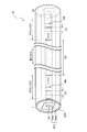
- FIG. 2 is a diagram illustrating a detailed configuration of an optical fiber used in a laser oscillator.
- FIG. 1 is an overall view of an apparatus for forming a refractive index modulation region.
- FIG. 4 is an enlarged view of the vicinity of an objective lens in the forming apparatus.
- FIG. 4 is a diagram illustrating a reflection spectrum of a grating region.
- FIG. 4 is a diagram showing the scattered light intensity of a first grating region including a refractive index modulation region formed under non-optimal conditions.
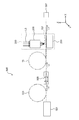
- FIG. 1 is a diagram illustrating a configuration of a laser oscillator.
- the laser oscillator 1 includes an excitation light source 11, a light introducing unit 13, an optical fiber 15, and a collimator 17.
- the excitation light source 11 is a semiconductor laser that outputs excitation light L2 incident on a clad 153 (described later) of the optical fiber 15.
- the excitation light L2 incident on the cladding 153 passes through the core 151, so that the excitation light L2 is absorbed in the core 151.
- light emission is amplified inside the core 151 by stimulated emission, and the inside of the optical fiber 15 is repeatedly reflected by mirrors at both ends, thereby leading to laser oscillation.
- the wavelength of light generated by the laser oscillation is determined by the element doped in the core 151.
- the light introducing unit 13 introduces the excitation light L ⁇ b> 2 output from the excitation light source 11 into the clad 153 of the optical fiber 15.
- the light introduction unit 13 includes an excitation light guide fiber 131 and an introduction lens 133.
- the excitation light waveguide fiber 131 is, for example, an optical fiber that guides the excitation light L2 output from the excitation light source 11 to the introduction lens 133.
- the introduction lens 133 is arranged near the entrance I, which is one end of the optical fiber 15, and introduces the excitation light L2 guided by the excitation light waveguide fiber 131 into the cladding 153.
- the optical fiber 15 functions as a laser medium and a resonator in the laser oscillator 1 of the present embodiment, and amplifies the laser light L1 generated by the irradiation of the excitation light L2 to cause laser oscillation.
- the collimator 17 is a lens that converts the laser light L1 emitted from the exit O of the optical fiber 15 into a parallel light beam.
- FIG. 2 is a diagram showing a detailed configuration of an optical fiber used in a laser oscillator.
- the optical fiber 15 has a core 151, a clad 153, a coat layer 155, and a grating region 157.
- the core 151 is excited by the excitation light L2 introduced from the light introducing unit 13 and generates a laser beam L1 having a wavelength determined by the substance doped in the core 151. That is, the core 151 functions as a laser medium of the laser oscillator 1.
- the core 151 is a fluoride fiber doped with a rare earth element.
- ZBLAN glass is a glass containing zirconium (Zr), barium (Ba), lanthanum (La), aluminum (Al), and sodium (Na) as main components.
- the core 151 is excited by the excitation light L2, so that the laser light L1 having a mid-infrared wavelength (specifically, around 2.8 ⁇ m) is emitted. Can be generated.
- the clad 153 is a layer formed so as to cover the core 151 on the outer periphery of the core 151 and having a refractive index smaller than that of the core 151.
- the clad 153 includes a first clad 153a and a second clad 153b.
- the first cladding 153a is a ZBLAN glass that covers the outer periphery of the core 151.
- the first cladding 153a has a smaller refractive index than the core 151. Therefore, the first clad 153a confines the laser light L1 inside the core 151 by reflecting the laser light L1 generated inside the core 151 at the interface with the core 151.
- the first cladding 153a has a quadrangular shape having four sides (four linear portions) in a cross section perpendicular to the length direction (FIG. 2).
- the first cladding 153a has a rectangular cross section in a direction perpendicular to the length direction, but is not limited thereto.
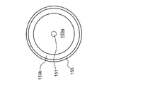
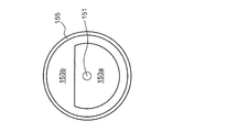
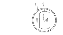
- the first cladding 153a is formed by cutting out a part of the circumference of a circle (FIG. 3A), a D-shape (FIG. 3B), a polygon (for example, an octagon (FIG. 3C)), or a D-shape. 3D) and the like.
- FIG. 3A is a diagram illustrating a first example of a cross-sectional shape of a first clad.
- FIG. 3B is a diagram showing a second example of the cross-sectional shape of the first clad.
- FIG. 3C is a diagram illustrating a third example of the cross-sectional shape of the first clad.
- FIG. 3D is a diagram illustrating a fourth example of the cross-sectional shape of the first clad.
- the second cladding 153b is a resin that covers the outer periphery of the first cladding 153a.
- the second cladding 153b is made of a low refractive index fluoride resin.
- the second cladding 153b has a smaller refractive index than the first cladding 153a. Therefore, the second cladding 153b reflects the pumping light L2 incident on the cladding 153 at the interface with the first cladding 153a, thereby confining the pumping light L2 inside the first cladding 153a and the core 151. Thereby, the excitation light L2 can pass through the inside of the first cladding 153a and the core 151 a plurality of times.
- the coating layer 155 is a resin (for example, acrylic resin) coating provided on the outermost periphery of the optical fiber 15.
- the coat layer 155 is a layer that prevents the optical fiber 15 (the first clad 153a and the core 151 made of ZBLAN glass) having deliquescence from coming into contact with moisture in the air.
- the coating layer 155 can prevent the optical fiber 15 from deteriorating.
- the grating area 157 is an area that reflects a part of the laser light L1 that has propagated through the core 151.
- the grating area 157 has a first grating area 157a and a second grating area 157b.
- the first grating region 157a is formed inside the core 151 near the entrance I of the excitation light L2 of the optical fiber 15.
- the first grating region 157a includes a plurality of refractive index modulation regions HR formed with a first interval D1.
- the refractive index modulation region HR is a region having a refractive index different from the refractive index of the core 151. That is, in the first grating region 157a, portions having a relatively high refractive index and portions having a relatively low refractive index are alternately arranged.
- the reflected light from a certain refractive index modulation region HR in the grating region 157 and the reflected light from an adjacent refractive index modulation region HR arranged at a first interval D1 have the same phase at the same location.
- the two reflected lights increase their mutual intensity by interference. Such reinforcement of the intensity of the reflected light occurs in the grating region 157, and as a result, light reflection occurs.
- the second grating region 157b is formed inside the core 151 near the exit O of the laser light L1 of the optical fiber 15. That is, the second grating region 157b is formed at a second interval D2 from the first grating region 157a in the length direction of the core 151. As shown in FIG. 3, the second grating region 157b includes a plurality of refractive index modulation regions HR formed at a first interval D1, similarly to the first grating region 157a.
- the second grating region 157b is a laser beam having a wavelength determined by the first interval D1 of the laser beam L1 propagating in the exit O direction through the core 151 based on the same principle as the reflection principle of the first grating region 157a. A part of the light L1 can be reflected toward the entrance I of the core 151. Of the laser light L1 propagating in the exit O direction, the laser light L1 that has passed through the second grating region 157b is output from the exit O. In order to output more laser light L1 from the exit O, it is preferable that the reflectance of the laser light L1 in the second grating region 157b is smaller than the reflectance in the first grating region 157a. Specifically, it is preferable that the formation length of the second grating region 157b is shorter than the formation length of the first grating region 157a.
- the core 151 of the optical fiber 15 has the first grating region 157a on the entrance I side of the excitation light L2, and has the second grating region 157b on the exit O side of the laser light L1, so that the specific wavelength can be increased.
- the laser beam L1 can be amplified between the first grating region 157a and the second grating region 157b. That is, laser oscillation of the laser light L1 can be realized in the core 151 without disposing a mirror or the like at any end of the optical fiber 15.
- the laser oscillator 1 including the optical fiber 15 of the present embodiment can reduce loss. As a result, laser light L1 having a higher intensity can be output efficiently.
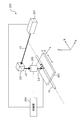
- FIG. 4A is an overall view of an apparatus for forming a refractive index modulation region.
- FIG. 4B is an enlarged view near the objective lens in the forming apparatus.
- the forming apparatus 200 mainly includes a reaction light source 201, a moving table 203, an objective lens 205, and a control unit 209.
- the reaction light source 201 is a light source that outputs the reaction light L3.
- the reaction light L3 causes a chemical reaction at a location of the core 151 where the reaction light L3 is irradiated, and makes the refractive index of the location different from the refractive index of the core 151.
- the reaction light L3 has sufficient energy with respect to the core 151 to cause a reaction for modulating the refractive index.
- the wavelength of the reaction light L3 is preferably short.
- the reaction light L3 interacts with the other portions forming the path of the reaction light L3, that is, the cladding 153 and the coat layer 155 of the optical fiber 15 and is not absorbed. That is, the wavelength of the reaction light L3 is preferably not short enough to interact with the cladding 153 and the coat layer 155. Therefore, as the reaction light L3, a light having the minimum wavelength that is absorbed by the cladding 153 and the coat layer 155 and does not interact with each other is selected.
- a general processing laser (YAG laser) is used as the reaction light source 201 in consideration of the condition of the reaction light L3 for the optical fiber 15 and the availability of the light source used as the reaction light source 201.
- the light from the reaction light source 201 is converted to a higher harmonic, and the reaction light L3 having a wavelength of 515 nm is output.
- the reaction light L3 can be focused inside the core 151 with a smaller spot diameter without changing the quality of the clad 153 and the coat layer 155.
- the reaction light source 201 generates femtosecond short-pulse laser light (pulse width: 400 fs (femtosecond)) having the above wavelength as the reaction light L3. Further, the output intensity of the reaction light L3 is adjusted, for example, in the range of 0.01 ⁇ J to 1 ⁇ J. The output intensity of the reaction light L3 is appropriately adjusted according to the type of the optical fiber 15 forming the refractive index modulation region HR.
- the moving table 203 is a stage that can move in the length direction of the optical fiber 15 (X direction in FIG. 4A) and in the height direction perpendicular to it (Z direction in FIG. 4A).
- a moving table (stage) using a piezo element or the like as a driving source can be used as the moving table 203. Accordingly, the optical fiber 15 can be moved with high precision in the length direction and the height direction, so that the refractive index modulation region HR can be formed at an accurate position inside the core 151 of the optical fiber 15.
- the optical fiber 15 forming the refractive index modulation region HR is arranged on the movable table 203.
- a pair of holding members 204 are fixed on the upper surface of the moving table 203 in the X direction.
- the pair of holding members 204 are clamps that hold the optical fiber 15 at two places while applying a slight tension in the X direction (length direction). By applying tension in the length direction (X direction) of the optical fiber 15, the optical fiber 15 can be prevented from being held between the holding members 204 in a bent state.
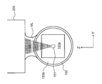
- the objective lens 205 is a lens that focuses the reaction light L3 propagated from the reaction light source 201 through the optical path changing member 207 (for example, a prism mirror) into the core 151. Further, as shown in FIG. 4B, a matching layer ML is disposed between the objective lens 205 and the coat layer 155 of the optical fiber 15.
- the matching layer ML is formed of, for example, an immersion oil (a Cargill standard refraction liquid) (an example of a liquid material) used for forming an “immersion objective lens” in an optical microscope.
- the refractive index of the matching layer ML is preferably larger than the refractive index (1.0) of air, more preferably in the range of 1.3 to 1.6, and is preferably about 1.5, which is close to the refractive index of the coat layer 155. Most preferred. With a refractive index greater than air, the matching layer ML can increase the numerical aperture of the objective lens 205. In this embodiment, immersion oil having a refractive index of about 1.5 is used as the matching layer ML.
- the matching layer ML which is immersion oil, is held by the objective lens 205 and the coat layer 155 of the optical fiber 15 due to the surface tension.
- the refractive index between the objective lens 205 and the coating layer 155 of the optical fiber 15 is higher than that of air.
- the control unit 209 includes, for example, a CPU, a RAM, a ROM, a storage device (SSD, hard disk, etc.), a computer system including various interfaces, a control unit for the reaction light source 201, and a control unit for the moving table 203. , The reaction light source 201, the moving table 203, and the objective lens 205 are controlled. Note that the control unit of the reaction light source 201 and the control unit of the movable base 203 are controlled by executing a program (the program is stored in a storage device of the computer system) in the computer system of the control unit 209. You may.
- the forming apparatus 200 further includes a camera (not shown) above the optical path changing member 207. With this camera, processing marks formed by the reaction light L3 can be observed via the objective lens 205. As a result, the appropriate position of the core 151 can be irradiated with the reaction light L3.
- the forming apparatus 200 further includes a white light source (not shown) for introducing white light from one side of the optical fiber 15 to the core 151.
- a white light source (not shown) for introducing white light from one side of the optical fiber 15 to the core 151.
- the reflection or transmission spectrum of the optical fiber 15 can be observed.
- the quality of the formed grating region 157 can be confirmed during the manufacturing by the forming apparatus 200, and the manufacturing time can be reduced and the quality of the grating region 157 can be stabilized.
- the formed grating region 157 may be evaluated by measuring the laser oscillation output generated by introducing the excitation light L2 into the cladding 153 in the forming apparatus 200. Specifically, the evaluation of the grating region 157 using the excitation light L2 can be performed by introducing an evaluation device 300 described later into the forming device 200.
- the moving table 203 may be movable in the Y direction.
- a two-dimensional refractive index modulation region HR can be formed in the cross section of the core 151.
- the forming apparatus 200 moves the focal position of the reaction light L3 by the moving table 203 and / or the objective lens 205, and moves the focal position of the reaction light L3 to an arbitrary position inside the core 151 of the optical fiber 15.
- the refractive index can be different.
- an arbitrary form of the refractive index modulation region HR can be formed inside the core 151.
- FIG. 5A is a diagram illustrating an example of a configuration of the evaluation device.
- the evaluation device 300 is incorporated in the forming device 200 described above. Therefore, the evaluation device 300 causes the white light L4 to enter the clad 153 while forming the grating region 157 in the forming device 200, and measures the spectrum intensity of the transmitted light L1 ′ transmitted through the grating region 157, thereby causing laser oscillation.
- the performance of the optical fiber 15 as a medium can be evaluated.
- the evaluation device 300 includes a white light source 301, an optical waveguide fiber 303, an introduction unit 305, and a first light measurement unit 307.
- the white light source 301 outputs white light L4.
- the white light L4 has a wavelength in the range of 1000 nm to 5000 nm including the wavelength of light that can be excited by the optical fiber 15.
- a white light LED light source for example, a white light LED light source, a white electric lamp, or the like can be used.
- the optical waveguide fiber 303 is an optical fiber that guides the white light L4 output from the white light source 301 to the introduction unit 305.
- the introduction unit 305 is arranged near the other end of the optical fiber 15 opposite to the one end where the grating region 157 is formed, and introduces the white light L4 into the clad 153 from the other end.
- the first light measurement unit 307 is, for example, an optical spectrum analyzer that measures the spectrum intensity of the transmitted light L1 ′ that has passed through the grating area 157.
- FIG. 5B is a diagram illustrating another example of the evaluation device.
- a mirror 305a is provided in the introduction unit 305.
- the mirror 305a is a half mirror, a dichroic mirror, or the like, and reflects the reflected light L1 ′′ reflected by the grating area 157 in a direction different from the white light L4.
- the mirror 305a transmits the white light L4.
- the second light measurement unit 309 is, for example, an optical spectrum analyzer that measures the spectral intensity of the reflected light L1 ′′ reflected by the grating area 157 and reflected by the mirror 305a.
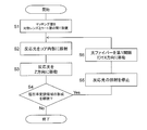
- FIG. 6 is a flowchart showing a method for manufacturing an optical fiber.
- the optical fiber 15 forming the refractive index modulation region HR is held by the holding member 204 of the forming apparatus 200 without peeling the coat layer 155. That is, in the present embodiment, in a state where the optical fiber 15 is coated with the coating layer 155, the core 151 is irradiated with the reaction light L3 to form the refractive index modulation region HR.
- step S1 the objective lens 205 is brought close to the optical fiber 15, and a matching layer ML is arranged between the objective lens 205 and the coat layer 155 of the optical fiber 15.
- immersion oil for forming the matching layer ML is injected into a gap between the objective lens 205 and the optical fiber 15.
- the immersion oil that is, the matching layer ML is held between the objective lens 205 and the coat layer 155 of the optical fiber 15 arranged close to each other by the surface tension.
- an air layer having a low refractive index is formed between the objective lens 205 and the coat layer 155 of the optical fiber 15 by using the surface tension. Without this, the matching layer ML can be easily formed.
- the reaction light source 201 After disposing the matching layer ML between the objective lens 205 and the coating layer 155 of the optical fiber 15, in step S2, the reaction light source 201 generates reaction light L3. After passing through the objective lens 205, the reaction light L3 generated by the reaction light source 201 propagates inside the matching layer ML.
- the refractive index of the matching layer ML is about 1.5, which is close to the refractive index of the coat layer 155 (the objective lens 205 and the clad 153). Therefore, the refraction at the interface between the matching layer ML and the coat layer 155 is smaller than the refraction at the interface between the air and the coat layer 155 when the matching layer ML is not provided.
- the reaction light L3 can be focused inside the core 151 with a small spot diameter.
- the moving table 203 is moved in the Z direction (an example of a direction perpendicular to the length direction of the core 151) in step S3. Accordingly, the spot SP of the reaction light L3 moves inside the core 151 in the diameter direction of the core 151.
- the moving speed when the spot SP of the reaction light L3 is moved in the Z direction depends on the frequency (frequency) of outputting the short-pulse reaction light L3 from the reaction light source 201 and / or the material constituting the optical fiber 15 or the like. It is determined based on. In the present embodiment, the moving speed is in the range of 30 ⁇ m to 3 mm / sec. In the present embodiment, the reaction light L3 is moved at the above moving speed, and the reaction light L3 is reciprocated 1 to 100 times in the Z direction in the core 151 (diameter of the core 151: 15 ⁇ m).
- the movement range of the reaction light L3 in the Z direction extends not only inside the core 151 but also to a part of the first cladding 153a.
- FIG. 7 is a diagram illustrating an example of the refractive index modulation region formed when the spot of the reaction light is moved in the diameter direction of the core.
- the moving speed when moving the spot SP of the reaction light L3 in the Z direction within a predetermined range, it is possible to form the refractive index modulation region HR uniform in the Z direction.
- the refractive index modulation region HR is not uniform in the Z direction.
- the inhomogeneous refractive index modulation region HR scatters the laser light L1 and lowers the laser oscillation efficiency in the optical fiber 15.
- the refractive index modulation region HR can be extended to a part of the first clad 153a.
- the laser light L1 is reflected at the interface between the core 151 and the first cladding 153a, the laser light L1 leaks from the outer periphery of the core 151 to the first cladding 153a by about a half wavelength of the laser light L1. Therefore, by extending the refractive index modulation region HR toward the first cladding 153a, the laser beam L1 leaked to the first cladding 153a can be reflected by the refractive index modulation region HR.
- step S4 After executing steps S2 and S3 to form one refractive index modulation region HR, it is determined in step S4 whether or not to form a further refractive index modulation region HR. In the present embodiment, whether or not to continue the formation of the refractive index modulation region HR is determined based on whether or not the number of formed refractive index modulation regions HR has reached a predetermined number. In another embodiment, the magnitude of the laser oscillation output generated in the optical fiber 15 in which the grating region 157 is formed may be used as a criterion for determining whether to continue formation of the refractive index modulation region HR.
- the reflection spectrum of the grating region 157 may be used as a criterion for determining whether to continue formation of the refractive index modulation region HR. For example, whether or not the intensity of light having a specific wavelength reflected by the grating region 157 has reached a desired level may be used as a criterion for determining whether to continue formation of the refractive index modulation region HR.
- the spectral shape of the light (the peak wavelength of the light, the half-width of the spectrum, the presence or absence of side lobes, and the like) may be used as a criterion.
- step S4 When it is determined that the formation of the refractive index modulation region HR is not to be continued based on the above determination criteria ("No" in step S4), the process of forming the refractive index modulation region HR is ended. On the other hand, when it is determined that the formation of the refractive index modulation region HR is to be continued (“Yes” in step S4), the irradiation of the reaction light L3 is stopped in step S5. Thereafter, in step S6, the movable table 203 is moved in the X direction, and the optical fiber 15 is moved in the length direction by the first interval D1.
- the above steps S2 to S4 are executed at the position in the length direction to form another refractive index modulation region HR.
- a plurality of refractive index modulation regions HR can be formed in the grating region 157 by separating the adjacent refractive index modulation regions HR by the first distance D1.
- Example (7-1) Conditions for Forming Refractive Index Modulated Region in Example
- the optical fiber 15 forming the grating region 157 was made of ZBLAN glass in which a core 151 having a square cross section was doped with erbium.
- the optical fiber 15 used in the embodiment is a double clad optical fiber in which the first clad 153a is a ZIBLAN glass and the second clad 153b is a resin.
- the matching layer ML is formed by applying a low auto-fluorescent immersion oil (refractive index: 1.515, viscosity: 450 mm 2 / s, manufactured by Olympus (registered trademark)) to the surface between the objective lens 205 and the coating layer 155 of the optical fiber 15. It was held by tension.
- a low auto-fluorescent immersion oil reffractive index: 1.515, viscosity: 450 mm 2 / s, manufactured by Olympus (registered trademark)
- the refractive index modulation region HR was formed using a reaction light L3 having a pulse width of 400 fs and a wavelength of 515 nm.
- the intensity of the reaction light L3 was adjusted at around 0.5 ⁇ J while confirming the irradiation mark by the reaction light L3.
- the interval (first interval D1) between the adjacent refractive index modulation regions HR was 970 nm. This interval can reflect the laser light L1 (wavelength: about 2.8 ⁇ m mid-infrared light) excited by the core 151 of erbium-doped ZBLAN glass using first-order diffraction.
- the moving speed of the spot SP of the reaction light L3 in the Z direction was 30 ⁇ m / sec. In this embodiment, the spot SP of the reaction light L3 is reciprocated once in the Z direction at the above moving speed to form the refractive index modulation region HR.
- Evaluation Results (7-2-1) Optical Microscope Image of Grating Area
- evaluation results of the optical fiber 15 having the grating area 157 manufactured in the example will be described.
- an optical microscope image of the grating region 157 formed in the optical fiber 15 will be described with reference to FIG.
- FIG. 8 is an optical microscope image of the grating region of the optical fiber.
- the grating region 157 corresponds to a portion where a line (vertical line) light and dark perpendicular to the length direction of the core 151 appears. Since the vertical line brightness is clear at a position corresponding to the grating region 157, it can be seen that a uniform refractive index modulation region HR is formed in the diameter direction of the core 151 using the above manufacturing conditions.
- the formation state of the grating region 157 can be visually confirmed by optical microscope observation, but it is difficult to accurately specify the microscopic structures of the grating region 157 and the refractive index modulation region HR. It is.
- a method of specifying the microscopic structures of the grating region 157 and the refractive index modulation region HR for example, observation with an electron microscope can be considered. To observe them with an electron microscope, a part of the core 151 is taken out. There is a need.
- the cladding 153 In order to take out a part of the core 151 to the outside, the cladding 153 needs to be peeled off, and the microscopic structures of the grating region 157 and the refractive index modulation region HR are destroyed by the operation up to observation with an electron microscope. The possibility is great. Further, in the case of an optical fiber formed of a deliquescent material such as ZBLAN glass, the refractive index modulation region HR is altered before the refractive index modulation region HR is taken out, and its structure changes.
- the formation is performed by evaluating the performance based on the optical characteristics of the grating region 157.
- the obtained refractive index modulation region HR was evaluated.
- the intensity of the light component of the wavelength (2.8 ⁇ m) is measured by the first light measuring unit 307, and the intensity of the light component of the wavelength corresponding to the laser light L 1 of the white light L 4 before transmission is transmitted to the first light measuring unit 307.
- the reflectance was calculated by dividing the difference between the measured intensity of the light component of the wavelength corresponding to the laser light L1 and the intensity of the light component of the wavelength corresponding to the laser light L1 of the white light L4 before transmission. .
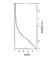
- FIG. 9 shows the relationship between the formation length of the grating region 157 and the reflectance of the laser beam L1 in the example. As shown in FIG. 9, even if the formed length is about 2.0 mm, the reflectance of the grating region 157 is close to 1. This indicates that the reflectance of one refractive index modulation region HR included in the grating region 157 can be increased by using the above-described conditions for forming the refractive index modulation region HR. It also shows that a laser beam L1 with sufficient intensity can be obtained even in the grating region 157 having a short formation length.
- the performance of the grating region 157 was evaluated based on the spectrum of white light L4 transmitted through the grating region 157 (transmission spectrum of the grating region).
- the reflection spectrum of the grating region 157 was obtained by using the above-described evaluation device 300. Specifically, the component intensity of each wavelength included in the white light L4 transmitted through the grating region 157 is measured by the first light measurement unit 307, and the component intensity of each wavelength included in the white light L4 before transmission is determined. The quotient of the intensity of the corresponding wavelength component of the white light L4 measured by the one light measurement unit 307 was calculated as the transmittance at the wavelength. After that, the above-described calculation of the transmittance was repeatedly performed for all the wavelengths included in the white light L4 to obtain a transmission spectrum.
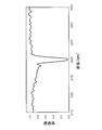
- FIG. 10 shows a transmission spectrum of the grating region 157 in the example.
- the transmittance of the grating region 157 is significantly reduced only at one specific wavelength (2.8 ⁇ m). That is, the reflectance of the grating region 157 is significantly increased at one wavelength.
- the grating region 157 having high wavelength selectivity of reflected light can be formed by using the above-described conditions for forming the refractive index modulation region HR.
- the grating region 157 of the example shows that the laser beam L1 having a wavelength of 2.8 ⁇ m can be reflected by reflection using first-order diffraction.
- the adjacent refractive index modulation regions HR may be separated from each other. Indicate that the refractive index modulation region HR is appropriately formed without overlapping.
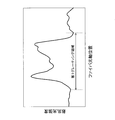
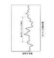
- red light (wavelength: 650 nm) was incident from the first grating region 157a side (entrance I side) and propagated through the core 151, and the scattered light intensity of the red light in each of the grating regions 157a and 157b was measured. .
- FIG. 11A shows the scattered light intensity of the first grating region 157a including the refractive index modulation region HR formed under non-optimal conditions.
- FIG. 11B shows the scattered light intensity of the second grating region 157b including the refractive index modulation region HR formed under the optimum condition.
- the laser light L1 is scattered in the grating region 157, and the core 151 It can be seen that the ratio of the laser light L1 that can propagate inside is reduced. That is, when the refractive index modulation region HR is not uniform inside the core 151, the oscillation efficiency of the laser light L1 is reduced.
- the refractive index modulation region HR is formed homogeneously.
- the refractive index modulation region HR can be made uniform inside the core 151, so that the laser light L1 does not scatter in the grating region 157, and the inside of the core 151
- the proportion of the laser beam L1 that can propagate can be increased. That is, when the refractive index modulation region HR is uniform inside the core 151, the oscillation efficiency of the laser beam L1 can be increased.
- the method for forming the refractive index modulation region HR has the following advantages as compared with the conventional method.
- a sufficient laser medium and an oscillator can be provided.
- the optical fiber 15 having excellent performance can be manufactured.
- a matching layer ML having a refractive index of about 1.5 is disposed between the objective lens 205 and the coating layer 155 of the optical fiber 15 so that the objective lens
- the spot diameter of the reaction light L3 inside the core 151 can be reduced.
- 515 nm which is the minimum wavelength that is not absorbed by the coat layer 155 and the clad 153, as the wavelength of the reaction light L3, the reaction light L3 is not degraded by the reaction light L3 without deteriorating the coat layer 155 and the clad 153. Can be focused inside the core 151 with a smaller spot diameter.
- Focusing the reaction light L3 with a small spot diameter inside the core 151 as described above means that the inside of the core 151 can be irradiated with the reaction light L3 having a large fluence. That is, by condensing the reaction light L3 into the core 151 with a small spot diameter as described above, the reaction of changing the refractive index is concentrated on the portion of the core 151 irradiated with the reaction light L3. Can be generated. As a result, the refractive index modulation region HR having a high reflectance and a small size can be formed inside the core 151.
- the refractive index modulation region HR having a high reflectivity and a small size can be formed inside the core 151, even if the number of the refractive index modulation regions HR formed in the grating region 157 is reduced, it is sufficient for laser oscillation.
- the grating region 157 having a high reflectivity can be formed.
- the optical fiber 15 has the grating region 157 with a formed length of at least about 1.5 mm to 2.0 mm, the laser medium and the resonator of the fiber laser are used. With sufficient performance. If the formation length of the grating region 157 can be reduced, the manufacturing time of the optical fiber 15 having the grating region 157 can be reduced.
- the grating region 157 Since the formation length of the grating region 157 can be reduced, the grating region 157 with stable quality can be formed. This is because if the formation length of the grating region 157 increases, the characteristics of the grating region 157 differ depending on the position in the length direction due to the distortion of the structure of the optical fiber 15 (twist, deviation of the position of the core 151, etc.). Because there is.
- the method according to the present embodiment in which the small-sized refractive index modulation region HR can be formed inside the core 151, is different from the conventional method in that the adjacent refractive index modulation regions HR overlap in the length direction of the core 151. Can be avoided. As a result, even if the interval (the first interval D1) between the adjacent refractive index modulation regions HR is set as the interval (about 1 ⁇ m) for reflecting the mid-infrared laser light L1 by using first-order diffraction, the adjacent refraction is used. The rate modulation regions HR do not overlap.
- the refractive index modulation regions HR do not overlap, so that only a specific wavelength determined by the first interval D1 is used. Can oscillate the laser light L1. That is, an ideal laser beam with excellent spectral characteristics can be output.
- the homogeneous refractive index modulation region HR can be formed inside the core 151.
- scattering of the laser beam L1 does not occur in the refractive index modulation region HR, so that an ideal laser beam having strong directivity and excellent spectral characteristics can be output.
- an arbitrary cross-sectional shape such as a circle, a D-shape, a polygon, or a star is used as a cross-sectional shape in a direction perpendicular to the length direction of the first clad 153a. But it is not limited to this.
- the reaction light L3 that forms the refractive index modulation region HR in the core 151 is perpendicularly incident from a plane having no curvature of the first cladding 153a.
- FIG. 12 is a diagram illustrating an example of a method of incident reaction light according to the second embodiment.
- the first cladding 153a preferably has at least one linear portion in a cross-sectional shape in a direction perpendicular to the length direction. That is, the cross-sectional shape of the first cladding 153a is preferably a D-shape, a polygon (for example, a quadrangle, an octagon, or the like).
- the spot shape of the reaction light L3 inside the core 151 is suppressed from being distorted, and the spot of the reaction light L3 inside the core 151 is suppressed. Shape can be reduced.
- the reaction light L3 can be appropriately focused inside the core 151 without distorting the spot shape.
- the first embodiment and the second embodiment have the following configurations and functions in common.
- a refractive index modulation region HR an example of a refractive index modulation region having a refractive index different from the refractive index of the core 151 is provided inside the core 151 (an example of the core).
- the method for manufacturing the optical fiber 15 includes the following steps.
- the objective lens 205 (an example of the objective lens) for condensing the reaction light L3 (an example of the reaction light) that changes the refractive index of the core 151 and the resin coat layer 155 (coat layer) provided on the outermost periphery of the optical fiber 15 And a step of arranging a matching layer ML (an example of a matching layer) having a refractive index close to that of the coat layer 155 (for example, step S1).
- a step of irradiating the reaction light L3 toward the inside of the core 151 to form the refractive index modulation region HR (for example, steps S2 to S6).
- the reaction light L3 is applied to the inside of the core 151 without peeling the outermost coat layer 155 of the optical fiber 15. This can prevent the optical fiber 15 from deteriorating during the formation of the refractive index modulation region HR inside the core 151. Further, it is not necessary to re-form the coat layer 155 after forming the refractive index modulation region HR.
- the refractive index of the space between the objective lens 205 and the coat layer 155 can be made higher than that of air.
- a small area inside the core 151 can be irradiated with the reaction light L3 having a high intensity. Therefore, a small refractive index modulation region HR having a large reflectance is formed. It can be formed inside the core 151.
- sufficient light reflection can be obtained even if the number of formed refractive index modulation regions HR inside the core 151 is small.
- the number of refractive index modulation regions formed inside the core can be reduced, it is not necessary to form the refractive index modulation region HR over a wide range in the length direction of the core.
- the variation in the refractive index modulation region HR due to the variation in the characteristics in the length direction of the optical fiber 15 is small, and the wavelength selectivity of the laser light that can oscillate is high.
- the small refractive index modulation regions HR can be formed inside the core 151, even if the distance between the adjacent refractive index modulation regions HR is reduced, these refractive index modulation regions HR do not overlap. As a result, in the optical fiber 15 manufactured by the above-described method, even a short-wavelength laser beam can be reflected by low-order diffraction, so that the wavelength selectivity of the short-wavelength laser beam that can oscillate is high.
- the present invention has been described above, but the present invention is not limited to the above embodiment, and various changes can be made without departing from the gist of the invention.
- a plurality of embodiments and modifications described in this specification can be arbitrarily combined as needed.
- the material of the optical fiber 15 and the first distance D1 between the refractive index modulation regions HR adjacent to each other can be appropriately changed according to the wavelength of the laser light L1 to be output by the laser oscillator 1.
- the conditions for forming the refractive index modulation region HR (for example, the wavelength, irradiation time, intensity, and the like of the reaction light L3) can be appropriately changed according to the optical characteristics of the material of the optical fiber 15.
- the method of forming the refractive index modulation region HR according to the above-described first embodiment and the second embodiment is not limited to the fluoride fiber, as long as the refractive index modulation can be induced by the reaction light L3. Applicable.
- the present invention can be applied not only to optical fibers but also to various optical waveguides.
- the moving table 203 may be movable in the diameter direction (Y direction) of the optical fiber 15 in addition to the length direction (X direction) and the height direction (Z direction) of the optical fiber 15. .
- the reaction light L3 may be moved two-dimensionally in the height direction and the diameter direction of the optical fiber 15 (that is, in the YZ plane).
- a two-dimensional refractive index modulation region HR can be formed in a cross section perpendicular to the length direction of the optical fiber 15.
- the present invention can be widely applied to a laser oscillator using an optical fiber as a laser medium and a resonator.
Landscapes
- Physics & Mathematics (AREA)
- General Physics & Mathematics (AREA)
- Optics & Photonics (AREA)
- Lasers (AREA)
- Optical Fibers, Optical Fiber Cores, And Optical Fiber Bundles (AREA)
Abstract
La présente invention empêche la dégénérescence d'une fibre optique au cours de la formation de régions à indice de réfraction modulé et permet de former des régions à indice de réfraction modulé qui ont une réflectivité élevée. L'invention concerne également un procédé de production d'une fibre optique 15 qui possède des régions à indice de réfraction modulé HR. Le procédé de production comprend : une étape consistant à agencer une couche d'adaptation ML qui possède un indice de réfraction qui est proche de l'indice de réfraction d'une couche de revêtement 155 d'une fibre optique 15 entre la couche de revêtement 155 et une lentille d'objectif 205 qui condense une lumière de réaction L3 qui est destinée à modifier l'indice de réfraction d'une âme 151 ; et une étape consistant à rayonner la lumière de réaction L3 en direction de l'intérieur de l'âme 151 pour former une région à indice de réfraction modulé HR.
Priority Applications (2)
| Application Number | Priority Date | Filing Date | Title |
|---|---|---|---|
| JP2020527316A JPWO2020003893A1 (ja) | 2018-06-29 | 2019-05-31 | 光ファイバーの製造方法、及び、光ファイバー |
| CN201980043722.6A CN112368614A (zh) | 2018-06-29 | 2019-05-31 | 光纤的制造方法以及光纤 |
Applications Claiming Priority (2)
| Application Number | Priority Date | Filing Date | Title |
|---|---|---|---|
| JP2018125551 | 2018-06-29 | ||
| JP2018-125551 | 2018-06-29 |
Publications (1)
| Publication Number | Publication Date |
|---|---|
| WO2020003893A1 true WO2020003893A1 (fr) | 2020-01-02 |
Family
ID=68987066
Family Applications (1)
| Application Number | Title | Priority Date | Filing Date |
|---|---|---|---|
| PCT/JP2019/021825 Ceased WO2020003893A1 (fr) | 2018-06-29 | 2019-05-31 | Procédé de production de fibre optique et fibre optique |
Country Status (3)
| Country | Link |
|---|---|
| JP (1) | JPWO2020003893A1 (fr) |
| CN (1) | CN112368614A (fr) |
| WO (1) | WO2020003893A1 (fr) |
Citations (2)
| Publication number | Priority date | Publication date | Assignee | Title |
|---|---|---|---|---|
| JP2009103786A (ja) * | 2007-10-22 | 2009-05-14 | Dainippon Printing Co Ltd | 回折格子作製用位相マスクを用いた回折格子作製方法 |
| WO2016123719A1 (fr) * | 2015-02-05 | 2016-08-11 | Grenier Jason R | Remodelage de guides d'ondes optique par modification d'indice de réfraction |
-
2019
- 2019-05-31 WO PCT/JP2019/021825 patent/WO2020003893A1/fr not_active Ceased
- 2019-05-31 JP JP2020527316A patent/JPWO2020003893A1/ja not_active Withdrawn
- 2019-05-31 CN CN201980043722.6A patent/CN112368614A/zh not_active Withdrawn
Patent Citations (2)
| Publication number | Priority date | Publication date | Assignee | Title |
|---|---|---|---|---|
| JP2009103786A (ja) * | 2007-10-22 | 2009-05-14 | Dainippon Printing Co Ltd | 回折格子作製用位相マスクを用いた回折格子作製方法 |
| WO2016123719A1 (fr) * | 2015-02-05 | 2016-08-11 | Grenier Jason R | Remodelage de guides d'ondes optique par modification d'indice de réfraction |
Non-Patent Citations (2)
| Title |
|---|
| BHARATHAN ET AL.: "Direct inscription of Bragg gratings into coated fluoride fibers for widely tunable and robust mid-infrared lasers", OPTICS EXPRESS, vol. 25, no. 24, 27 November 2017 (2017-11-27), pages 30013 - 30019, XP055666830, DOI: 10.1364/OE.25.030013 * |
| LIN ET AL.: "Fiber surface Bragg grating waveguide for refractive index measurements", OPTICS LETTERS, vol. 42, no. 9, 1 May 2017 (2017-05-01), pages 1684 - 1687, XP055666834, ISSN: 0146-9592, DOI: 10.1364/OL.42.001684 * |
Also Published As
| Publication number | Publication date |
|---|---|
| JPWO2020003893A1 (ja) | 2021-07-15 |
| CN112368614A (zh) | 2021-02-12 |
Similar Documents
| Publication | Publication Date | Title |
|---|---|---|
| US7532791B2 (en) | Ultrafast laser machining system and method for forming diffractive structures in optical fibers | |
| CN109792129B (zh) | 单片可见光波长光纤激光器 | |
| JPH10186246A (ja) | レーザビームの補正方法及び装置 | |
| EP2856584B1 (fr) | Filtre spatial à haute puissance | |
| WO2019176572A1 (fr) | Oscillateur laser, dispositif d'usinage laser, fibre optique, procédé de production de fibre optique et dispositif de production de fibre optique | |
| US9110246B2 (en) | High power spatial filter | |
| US9001850B2 (en) | Excitation unit for a fiber laser | |
| JP2006516811A (ja) | ファイバレーザ | |
| JP2017181777A (ja) | 透明光学材料の改質方法、光デバイス、光デバイスの製造方法、及び光デバイスの製造装置 | |
| EP1703601A1 (fr) | Oscillateur laser à fibre | |
| US7283293B2 (en) | High efficiency optical amplifying fiber | |
| JPH1123878A (ja) | レーザ装置及びレーザ加工装置 | |
| JPWO2020003893A1 (ja) | 光ファイバーの製造方法、及び、光ファイバー | |
| JP6640094B2 (ja) | レーザ光照射装置 | |
| JP6360862B2 (ja) | ファイバチャープドグレーティング素子及びファイバレーザ | |
| JPH1123867A (ja) | ファイババンドル及びファイババンドルの製造方法 | |
| JPWO2006098313A1 (ja) | 光増幅器およびレーザ装置 | |
| JP4287007B2 (ja) | レーザー装置並びにこれを用いたレーザー加工装置及び光信号増幅装置 | |
| JP2005200277A (ja) | 光ファイバの製造方法 | |
| JP3941063B2 (ja) | ファイバレーザ発振装置 | |
| JP4144566B2 (ja) | ファイバレーザ発振装置 | |
| WO2007116563A1 (fr) | Source de lumière | |
| KR100550819B1 (ko) | 공심형 광섬유 레이저 | |
| JP6826777B2 (ja) | 光源装置、及びこれを備えた光学分析装置 | |
| JP2005150229A (ja) | 光ファイバレーザ |
Legal Events
| Date | Code | Title | Description |
|---|---|---|---|
| 121 | Ep: the epo has been informed by wipo that ep was designated in this application |
Ref document number: 19826681 Country of ref document: EP Kind code of ref document: A1 |
|
| ENP | Entry into the national phase |
Ref document number: 2020527316 Country of ref document: JP Kind code of ref document: A |
|
| NENP | Non-entry into the national phase |
Ref country code: DE |
|
| 122 | Ep: pct application non-entry in european phase |
Ref document number: 19826681 Country of ref document: EP Kind code of ref document: A1 |