WO2020003974A1 - Dispositif de commande d'embrayage pour véhicule à selle - Google Patents
Dispositif de commande d'embrayage pour véhicule à selle Download PDFInfo
- Publication number
- WO2020003974A1 WO2020003974A1 PCT/JP2019/022721 JP2019022721W WO2020003974A1 WO 2020003974 A1 WO2020003974 A1 WO 2020003974A1 JP 2019022721 W JP2019022721 W JP 2019022721W WO 2020003974 A1 WO2020003974 A1 WO 2020003974A1
- Authority
- WO
- WIPO (PCT)
- Prior art keywords
- wheel speed
- clutch
- control
- speed
- vehicle
- Prior art date
- Legal status (The legal status is an assumption and is not a legal conclusion. Google has not performed a legal analysis and makes no representation as to the accuracy of the status listed.)
- Ceased
Links
Images









Classifications
-
- F—MECHANICAL ENGINEERING; LIGHTING; HEATING; WEAPONS; BLASTING
- F16—ENGINEERING ELEMENTS AND UNITS; GENERAL MEASURES FOR PRODUCING AND MAINTAINING EFFECTIVE FUNCTIONING OF MACHINES OR INSTALLATIONS; THERMAL INSULATION IN GENERAL
- F16D—COUPLINGS FOR TRANSMITTING ROTATION; CLUTCHES; BRAKES
- F16D48/00—External control of clutches
- F16D48/06—Control by electric or electronic means, e.g. of fluid pressure
-
- F—MECHANICAL ENGINEERING; LIGHTING; HEATING; WEAPONS; BLASTING
- F16—ENGINEERING ELEMENTS AND UNITS; GENERAL MEASURES FOR PRODUCING AND MAINTAINING EFFECTIVE FUNCTIONING OF MACHINES OR INSTALLATIONS; THERMAL INSULATION IN GENERAL
- F16D—COUPLINGS FOR TRANSMITTING ROTATION; CLUTCHES; BRAKES
- F16D2500/00—External control of clutches by electric or electronic means
- F16D2500/10—System to be controlled
- F16D2500/102—Actuator
- F16D2500/1026—Hydraulic
-
- F—MECHANICAL ENGINEERING; LIGHTING; HEATING; WEAPONS; BLASTING
- F16—ENGINEERING ELEMENTS AND UNITS; GENERAL MEASURES FOR PRODUCING AND MAINTAINING EFFECTIVE FUNCTIONING OF MACHINES OR INSTALLATIONS; THERMAL INSULATION IN GENERAL
- F16D—COUPLINGS FOR TRANSMITTING ROTATION; CLUTCHES; BRAKES
- F16D2500/00—External control of clutches by electric or electronic means
- F16D2500/10—System to be controlled
- F16D2500/11—Application
- F16D2500/1107—Vehicles
- F16D2500/1117—Motorcycle
-
- F—MECHANICAL ENGINEERING; LIGHTING; HEATING; WEAPONS; BLASTING
- F16—ENGINEERING ELEMENTS AND UNITS; GENERAL MEASURES FOR PRODUCING AND MAINTAINING EFFECTIVE FUNCTIONING OF MACHINES OR INSTALLATIONS; THERMAL INSULATION IN GENERAL
- F16D—COUPLINGS FOR TRANSMITTING ROTATION; CLUTCHES; BRAKES
- F16D2500/00—External control of clutches by electric or electronic means
- F16D2500/30—Signal inputs
- F16D2500/31—Signal inputs from the vehicle
- F16D2500/3108—Vehicle speed
- F16D2500/3109—Vehicle acceleration
-
- F—MECHANICAL ENGINEERING; LIGHTING; HEATING; WEAPONS; BLASTING
- F16—ENGINEERING ELEMENTS AND UNITS; GENERAL MEASURES FOR PRODUCING AND MAINTAINING EFFECTIVE FUNCTIONING OF MACHINES OR INSTALLATIONS; THERMAL INSULATION IN GENERAL
- F16D—COUPLINGS FOR TRANSMITTING ROTATION; CLUTCHES; BRAKES
- F16D2500/00—External control of clutches by electric or electronic means
- F16D2500/30—Signal inputs
- F16D2500/31—Signal inputs from the vehicle
- F16D2500/3114—Vehicle wheels
- F16D2500/3115—Vehicle wheel speed
-
- F—MECHANICAL ENGINEERING; LIGHTING; HEATING; WEAPONS; BLASTING
- F16—ENGINEERING ELEMENTS AND UNITS; GENERAL MEASURES FOR PRODUCING AND MAINTAINING EFFECTIVE FUNCTIONING OF MACHINES OR INSTALLATIONS; THERMAL INSULATION IN GENERAL
- F16D—COUPLINGS FOR TRANSMITTING ROTATION; CLUTCHES; BRAKES
- F16D2500/00—External control of clutches by electric or electronic means
- F16D2500/30—Signal inputs
- F16D2500/31—Signal inputs from the vehicle
- F16D2500/3114—Vehicle wheels
- F16D2500/3118—Slip of vehicle wheels
Definitions
- the present invention relates to a clutch control device for a saddle type vehicle.
- This application claims priority based on Japanese Patent Application No. 2018-123814 filed in Japan on June 29, 2018 and Japanese Patent Application No. 2018-204514 filed in Japan on October 30, 2018. , The contents of which are incorporated herein.
- a clutch device for connecting and disconnecting power transmission between a prime mover and drive wheels may be provided with a back torque limiter.
- the back torque limiter is a mechanism for limiting an engine brake (including a regenerative brake when the electric motor includes an electric motor) acting on the drive wheels due to the resistance of the motor.
- the back torque limiter mechanically reduces the clutch capacity when a back torque exceeding a specified value acts on a cam mechanism provided in the clutch device.
- the back torque is a torque at which the engine is turned by the driving force from the driving wheels when the vehicle decelerates.
- the clutch device releases the back torque by the operation of the back torque limiter to prevent application of excessive engine brake to the drive wheels.
- the above-mentioned back torque is set to a specified value or more.
- the above-mentioned back torque can be more than the above-mentioned specification in a state where the driving wheels are in contact with the ground and are sufficiently gripped (in a state where there is a sufficient contact load).
- the ground load of the rear wheel which is the driving wheel, becomes too small, and the rear wheel may float off the road surface. If the rear wheel loses grip, the rear wheel will suddenly decelerate when the engine brakes.
- a clutch control device for a saddle-ride type vehicle includes a rear wheel that is a driving wheel, a front wheel that is a driven wheel, a driving motor for traveling, and a motor for driving the vehicle.
- the control unit may control the rear wheel speed, which is the rotation speed of the rear wheel, to be higher than the front wheel speed, which is the rotation speed of the front wheel. Then, it may be determined that the rear wheel is in the ground contact load lowering state based on that the rear wheel has become lower than a predetermined difference.
- the control unit may correct the front wheel speed as the rear wheel speed to be compared with the front wheel speed. Wheel speed may be used.
- the corrected wheel speed may be a change amount of the rear wheel speed at the same time as the front wheel speed at the time of the wheel speed correction. It may be obtained by adding.
- the saddle-ride type vehicle is in an upright posture, and the difference between the front and rear wheel speeds is less than a predetermined value.
- the wheel speed correction may be started from a specific point in time when the throttle of the prime mover is closed.
- a value obtained by dividing the front wheel speed by the corrected wheel speed is used as a first parameter
- a value obtained by subtracting the corrected wheel speed from the front wheel speed may be used as a second parameter
- the slipper control may be interposed according to at least one of the first parameter and the second parameter.
- the slipper control when the vehicle speed is equal to or higher than the first vehicle speed, the slipper control is interposed according to the first parameter, and the vehicle speed is reduced to the first vehicle speed.
- the slipper control When the vehicle speed is lower than one vehicle speed and higher than or equal to the second vehicle speed, the slipper control may be interposed according to the second parameter.
- the control unit may open the throttle of the prime mover with the slipper control interposed.
- the intervention of the slipper control may be canceled in response to at least one of the following facts and / or that the reduced state of the contact load of the rear wheel has been eliminated.
- the clutch capacity is reduced when a decrease in the ground contact load such that the rear wheel floats when the saddle-ride type vehicle is decelerated is detected.
- Slipper control can be performed. As a result, it is possible to secure an appropriate engine brake during normal traveling while ensuring the ground contact load of the rear wheels, and to shift to slipper control during rapid deceleration when the rear wheels float. Since the slipper control weakens the engine brake of the rear wheel, the occurrence of hopping and snaking due to the engine brake when the ground load of the rear wheel is released is suppressed.
- the clutch capacity can be made variable as compared with a mechanical back torque limiter.
- the rear wheel speed is lower than the front wheel speed, so that the ground load of the rear wheel is released. Can be easily and reliably determined.
- the actual front and rear wheel speeds are affected not only by the difference in the tire outer diameter of the front and rear wheels, but also by the circumferential change of the tire. . Changes in the circumference of the tire are caused by, for example, the brand of the tire, wear, expansion due to centrifugal force, and the like. For this reason, even if the front and rear wheels are rotating without slipping on the road surface, there may be a difference in front and rear wheel speed due to a change in the circumference of the tire.
- a corrected wheel speed for comparison is calculated based on the front wheel speed, and the corrected wheel speed is compared with the front wheel speed. It is possible to accurately detect a decrease in wheel speed and prevent an inadvertent decrease in clutch capacity (a decrease in engine brake).
- the amount of change in the rear wheel speed is added to the front wheel speed to correct the wheel speed.
- the load can be reduced.
- the saddle-ride type vehicle is in a decelerating state in which the throttle of the prime mover is closed in an upright position, and the difference between the front and rear wheel speeds is the rear wheel.
- an appropriate value is selected from the two types of parameters to determine the intervention of the slipper control (the determination that the rear wheel is slipping).
- the slipper control can be performed with a minimum necessary frequency.
- a slip determination can be performed by selecting an appropriate parameter according to the vehicle speed.
- the slipper control when the vehicle speed is low, the slipper control is not intervened, so that the system load can be suppressed.
- the clutch control device for a saddle-ride type vehicle described in the above (9) of the present invention at least one of the fact that the saddle-ride type vehicle has shifted to acceleration and that the reduction in the contact load of the rear wheels has been eliminated.
- the clutch control device for a saddle-ride type vehicle described in the above (10) of the present invention in a region where the bank angle of the vehicle body is large, an accurate wheel speed difference is obtained because the patterns of the tread surfaces of the front and rear wheels are different.
- the bank angle of the vehicle body is equal to or larger than a predetermined value, the slipper control of the clutch is performed regardless of the wheel speed difference.
- FIG. 2 is a left side view of the motorcycle according to the embodiment of the present invention.
- FIG. 2 is a sectional view of a transmission and a change mechanism of the motorcycle. It is a schematic explanatory view of a clutch operation system including a clutch actuator.
- FIG. 2 is a block diagram of a transmission system.
- FIG. 5 is an explanatory diagram showing a transition of a clutch control mode.
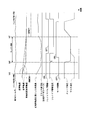
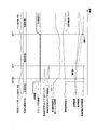
- 4 is a graph showing an outline of slipper control during deceleration of the motorcycle. It is a graph which shows the time change of the control parameter of the slipper control at the time of the above-mentioned deceleration. It is a graph which shows the time change of the control parameter of the said slipper control at the time of the said deceleration.
- FIG. 1 shows an outline of slipper control during deceleration of the motorcycle. It is a graph which shows the time change of the control parameter of the slipper control at the time of the above-mentioned deceleration. It is a graph
- FIG. 3 is an explanatory diagram showing a vehicle body situation at the time of deceleration of the motorcycle. It is a graph which shows the outline of the wheel speed correction of the slipper control at the time of the above-mentioned deceleration.
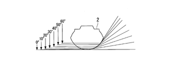
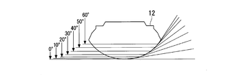
- FIG. 14 is an operation explanatory view of the second embodiment, and is a cross-sectional view showing a change in a contact angle and a contact point of a front wheel.
- FIG. 10 is an operation explanatory view of the second embodiment, and is a cross-sectional view showing a change between a contact angle and a contact point of a rear wheel. It is an operation explanatory view of the second embodiment, and is a graph showing a correlation between a circumferential length change rate ratio of front and rear wheels and a bank angle.
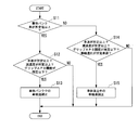
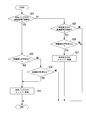
- 9 is a flowchart illustrating a process performed by an ECU when determining whether to shift to wheel speed correction in the first and second embodiments. It is a flowchart which shows the process which ECU performs at the time of determining whether to perform slipper control in 1st and 2nd embodiment. It is a flowchart which shows the process performed by ECU at the time of determining whether to end the slipper control in the first and second embodiments.
- the first embodiment is applied to a motorcycle 1 as an example of a saddle type vehicle.
- a front wheel 2 of the motorcycle 1 is supported by lower ends of a pair of left and right front forks 3.
- the upper portions of the left and right front forks 3 are supported by a head pipe 6 at the front end of a vehicle body frame 5 via a steering stem 4.
- a bar-type steering handle 4 a is mounted on the top bridge of the steering stem 4.
- the vehicle body frame 5 includes a head pipe 6, a main tube 7 extending downward and rearward from a center of the head pipe 6 in a vehicle width direction (lateral direction), a left and right pivot frame 8 extending below a rear end of the main tube 7, And a seat frame 9 connected to the rear of the tube 7 and the left and right pivot frames 8.
- the front ends of the swing arms 11 are pivotably supported by the left and right pivot frames 8. At the rear end of the swing arm 11, a rear wheel 12 of the motorcycle 1 is supported.
- a fuel tank 18 is supported above the left and right main tubes 7.
- a front seat 19 and a rear seat cover 19a are supported side by side.
- the periphery of the seat frame 9 is covered with a rear cowl 9a.
- a power unit PU which is a prime mover of the motorcycle 1, is suspended.
- the power unit PU is linked to the rear wheel 12 via, for example, a chain-type transmission mechanism.
- the power unit PU integrally includes an engine (internal combustion engine, prime mover) 13 located on the front side and a transmission 21 located on the rear side.
- the engine 13 is, for example, a multi-cylinder engine in which the rotation axis of a crankshaft 14 extends along the left-right direction (vehicle width direction).
- the engine 13 has a cylinder 16 erected above a front part of the crankcase 15.
- the rear part of the crankcase 15 is a transmission case 17 that houses the transmission 21.
- the transmission 21 is a stepped transmission having a main shaft 22, a counter shaft 23, and a transmission gear group 24 extending over both shafts 22, 23.
- the counter shaft 23 constitutes the transmission 21 and thus the output shaft of the power unit PU.
- An end of the counter shaft 23 projects to the rear left side of the crankcase 15 and is connected to the rear wheel 12 via the above-mentioned chain type transmission mechanism.
- the transmission gear group 24 has gears for the number of gears supported by the shafts 22 and 23, respectively.
- the transmission 21 is of a constant mesh type in which the corresponding gear pairs of the transmission gear group 24 are always meshed between the two shafts 22 and 23.
- the plurality of gears supported by both shafts 22 and 23 are classified into a free gear rotatable with respect to the corresponding shaft, and a slide gear (shifter) spline-fitted to the corresponding shaft.
- One of the free gear and the slide gear has an axially convex dog, and the other has an axially concave slot for engaging the dog. That is, the transmission 21 is a so-called dog mission.
- the main shaft 22 and the counter shaft 23 of the transmission 21 are arranged in front of and behind the crankshaft 14.
- a clutch device 26 operated by a clutch actuator 50 (see FIG. 3) is coaxially arranged.
- the clutch device 26 is, for example, a wet multi-plate clutch, and is a so-called normally open clutch. That is, the clutch device 26 is in a connected state in which power can be transmitted by supplying hydraulic pressure from the clutch actuator 50, and returns to a disconnected state in which power cannot be transmitted when hydraulic pressure is not supplied from the clutch actuator 50.
- the rotational power of the crankshaft 14 is transmitted to the main shaft 22 via the clutch device 26, and transmitted from the main shaft 22 to the counter shaft 23 via an arbitrary gear pair of the transmission gear group 24.
- a drive sprocket 27 of the above-described chain type transmission mechanism is attached to a left end portion of the countershaft 23 protruding to the rear left side of the crankcase 15.
- the clutch device 26 includes a back torque limiter (not shown). The back torque limiter mechanically reduces the clutch capacity when a back torque exceeding a specified value acts on a cam mechanism provided in the clutch device 26.
- a change mechanism 25 for switching a gear pair of the transmission gear group 24 Above the rear of the transmission 21 is accommodated a change mechanism 25 for switching a gear pair of the transmission gear group 24.
- the change mechanism 25 operates a plurality of shift forks 36 a in accordance with a pattern of a lead groove formed on the outer periphery of the shift gear group 24 by rotating a hollow cylindrical shift drum 36 parallel to the shafts 22 and 23.
- the gear pair used for power transmission between the two shafts 22 and 23 is switched.
- the change mechanism 25 has a shift spindle 31 parallel to the shift drum 36.
- the shift arm 31a fixed to the shift spindle 31 rotates the shift drum 36, and moves the shift fork 36a in the axial direction according to the pattern of the lead groove, so that the power within the transmission gear group 24 is changed.
- the transmissible gear pair is switched (that is, the gear position is switched).
- the shift spindle 31 has a shaft outer portion 31b protruding outward (leftward) in the vehicle width direction of the crankcase 15 so that the change mechanism 25 can be operated.
- a shift load sensor 42 (shift operation detecting means) is coaxially mounted on the shaft outer portion 31b of the shift spindle 31.
- a swing lever 33 is attached to the shaft outer portion 31b of the shift spindle 31 (or the rotation shaft of the shift load sensor 42).
- the swing lever 33 extends rearward from a base end portion 33a which is clamped and fixed to the shift spindle 31 (or the rotation shaft), and the upper end portion of a link rod 34 swings at a tip end portion 33b thereof via an upper ball joint 34a. It is movably connected.
- a lower end of the link rod 34 is swingably connected to a shift pedal 32 operated by a driver with a foot via a lower ball joint (not shown).
- the front end of the shift pedal 32 is supported at the lower part of the crankcase 15 via a shaft extending in the left-right direction so as to be vertically swingable.
- a pedal portion for hanging the driver's toe placed on the step 32a is provided, and at the front and rear intermediate portion of the shift pedal 32, the lower end of a link rod 34 is connected.
- the driver performs only the shifting operation of the transmission 21 (the foot operation of the shift pedal 32), and the connecting / disconnecting operation of the clutch device 26 is automatically performed by electric control according to the operation of the shift pedal 32.
- a so-called semi-automatic transmission system (automatic clutch-type transmission system) is adopted.
- the transmission system includes a clutch actuator 50, an ECU 60 (Electronic Control Unit, control unit), and various sensors 41 to 45.
- the ECU 60 detects detection information from a gear position sensor 41 that detects a gear position based on the rotation angle of the shift drum 36, a shift load sensor 42 (for example, a torque sensor) that detects an operating torque input to the shift spindle 31, and a throttle opening.
- a gear position sensor 41 that detects a gear position based on the rotation angle of the shift drum 36
- a shift load sensor 42 for example, a torque sensor
- the operation of the clutch actuator 50 is controlled, and the operation of the ignition device 46 and the fuel injection device 47 are controlled.
- the vehicle speed sensor 44 includes a front wheel speed sensor 44f that detects the rotation speed of the front wheel 2, and a rear wheel speed sensor 44r that detects the rotation speed of the rear wheel 12.
- the engine speed is controlled by a throttle by wire (TBW) including a throttle valve and an accelerator grip.
- TW throttle by wire
- the ECU 60 also receives detection information from oil pressure sensors 57 and 58, a shift operation detection switch (shift neutral switch) 48, and a gyro sensor 49 that detects the state (movement) of the vehicle body.
- the gyro sensor 49 is an IMU (inertial measurement unit: inertial measurement device), and outputs a signal corresponding to the acceleration component in the detection direction to the ECU 60.
- the gyro sensor 49 may be built in the ECU 60.
- the ECU 60 includes a hydraulic control unit 61 and a wheel speed difference determination unit (rear lift detection unit) 62.
- the hydraulic control unit 61 includes a slipper control unit 61a.
- the wheel speed difference determination section 62 includes a wheel speed correction section 62a.
- Reference numeral 60A in the figure indicates the clutch control device of the first embodiment.
- the clutch actuator 50 is controlled to be operated by the ECU 60, so that the hydraulic pressure for connecting and disconnecting the clutch device 26 can be controlled.
- the clutch actuator 50 includes an electric motor 52 (hereinafter, simply referred to as a motor 52) as a driving source, and a master cylinder 51 driven by the motor 52.
- the clutch actuator 50 and the hydraulic circuit device 53 provided between the master cylinder 51 and the hydraulic supply / discharge port 50p constitute an integral clutch control unit 50A.
- the ECU 60 calculates a target value (a target hydraulic pressure) of the hydraulic pressure supplied to the slave cylinder 28 for connecting and disconnecting the clutch device 26 based on a preset calculation program.
- the clutch control unit 50A is controlled so that the hydraulic pressure on the 28 side (slave hydraulic pressure) approaches the target hydraulic pressure.
- the master cylinder 51 allows the piston 51b in the cylinder main body 51a to stroke by the driving of the motor 52 so that the hydraulic oil in the cylinder main body 51a can be supplied to and discharged from the slave cylinder 28.
- reference numeral 55 denotes a conversion mechanism as a ball screw mechanism
- reference numeral 54 denotes a transmission mechanism extending over the motor 52 and the conversion mechanism 55
- reference numeral 51e denotes a reservoir connected to the master cylinder 51.
- the hydraulic circuit device 53 has a valve mechanism (solenoid valve 56) for opening or closing an intermediate portion of a main oil passage (hydraulic oil supply / discharge oil passage) 53m extending from the master cylinder 51 to the clutch device 26 side (slave cylinder 28 side). are doing.
- the main oil passage 53m of the hydraulic circuit device 53 is divided into an upstream oil passage 53a closer to the master cylinder 51 than the solenoid valve 56, and a downstream oil passage 53b closer to the slave cylinder 28 than the solenoid valve 56.
- the hydraulic circuit device 53 further includes a bypass oil passage 53c that bypasses the solenoid valve 56 and communicates the upstream oil passage 53a and the downstream oil passage 53b.
- the solenoid valve 56 is a so-called normally open valve.
- the bypass oil passage 53c is provided with a one-way valve 53c1 that allows hydraulic oil to flow only in the direction from the upstream side to the downstream side.
- An upstream oil pressure sensor 57 for detecting the oil pressure of the upstream oil passage 53a is provided upstream of the solenoid valve 56.
- a downstream oil pressure sensor 58 for detecting the oil pressure of the downstream oil passage 53b is provided downstream of the solenoid valve 56.
- the clutch control unit 50A is housed, for example, in the rear cowl 9a.
- the slave cylinder 28 is attached to the rear left side of the crankcase 15.
- the clutch control unit 50A and the slave cylinder 28 are connected via a hydraulic pipe 53e (see FIG. 3).
- the slave cylinder 28 is coaxially arranged on the left side of the main shaft 22.
- the slave cylinder 28 presses a push rod 28a penetrating through the main shaft 22 to the right.
- the slave cylinder 28 presses the push rod 28a to the right to operate the clutch device 26 to the connected state via the push rod 28a.
- the slave cylinder 28 releases the pressing of the push rod 28a and returns the clutch device 26 to the disconnected state.
- a solenoid valve 56 is provided in the hydraulic circuit device 53 of the clutch control unit 50A, and the solenoid valve 56 is closed after hydraulic pressure is supplied to the clutch device 26 side. Thereby, energy consumption is suppressed by maintaining the supply oil pressure to the clutch device 26 side and supplementing the oil pressure by the pressure decrease (recharge by the leak amount).
- the clutch control device 60A of the first embodiment has three types of clutch control modes.
- the clutch control mode includes a clutch control mode changeover switch 59 (FIG. 4) among three modes: an automatic mode M1 for performing automatic control, a manual mode M2 for performing manual operation, and a manual intervention mode M3 for performing temporary manual operation.
- the state changes appropriately according to the operation of the clutch lever 4b (see FIG. 1) and the clutch lever 4b (see FIG. 1).
- An object including the manual mode M2 and the manual intervention mode M3 is referred to as a manual system M2A.
- the clutch control device 60A also functions as a clutch-by-wire system in which the clutch lever 4b and the clutch device 26 are electrically connected.
- the automatic mode M1 is a mode in which the clutch device 26 is controlled by calculating a clutch capacity suitable for a running state by automatic start / shift control.
- the manual mode M2 is a mode in which the clutch capacity is calculated in accordance with a clutch operation instruction from the occupant to control the clutch device 26.
- the manual intervention mode M3 is a temporary manual operation mode in which a clutch operation instruction from an occupant is received during the automatic mode M1, and a clutch capacity is calculated from the clutch operation instruction to control the clutch device 26. It should be noted that, when the occupant stops operating the clutch lever 4b (completely releases) during the manual intervention mode M3, the mode is set to return to the auto mode M1.
- the clutch control device 60 ⁇ / b> A of the first embodiment generates an oil pressure for clutch control by driving an oil pump (not shown) with the rotational driving force of the engine 13. For this reason, the clutch control device 60A starts the control from the clutch-off state (disconnected state) in the auto mode M1 when the system is started. Further, the clutch control device 60A is set to return to the clutch off in the automatic mode M1 because the clutch operation is not required when the engine 13 is stopped.
- the clutch control is performed automatically, and the motorcycle 1 can run without operating the lever.
- the clutch capacity is controlled by the throttle opening, engine speed, vehicle speed, and shift sensor output.
- the motorcycle 1 can be started without stalling only by the throttle operation, and can be shifted only by the shift operation.
- the clutch device 26 may be automatically disconnected at an extremely low speed corresponding to idling.
- the manual intervention mode M3 is set by gripping the clutch lever 4b, and the clutch device 26 can be arbitrarily disengaged.
- the clutch capacity is controlled by the lever operation by the occupant.
- the auto mode M1 and the manual mode M2 can be switched by operating the clutch control mode switch 59 (see FIG. 4) while the vehicle is stopped.
- the clutch control device 60A may include an indicator indicating that the lever operation is valid at the time of transition to the manual system M2A (manual mode M2 or manual intervention mode M3).
- the clutch control is basically performed manually, and the clutch oil pressure can be controlled according to the operation angle of the clutch lever 4b.
- the connection and disconnection of the clutch device 26 can be controlled with the intention of the occupant, and the vehicle can be connected and run even at an extremely low speed equivalent to idling.
- the engine may stall depending on the lever operation, and automatic start cannot be performed only by the throttle operation.
- the clutch control automatically intervenes during the shift operation.
- the clutch actuator 50 automatically connects and disconnects the clutch device 26. However, when the manual clutch operation on the clutch lever 4b is performed, the manual operation is temporarily intervened in the automatic control of the clutch device 26. (Manual intervention mode M3).
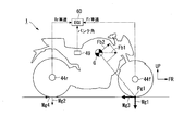
- the front contact load Mg1 front wheel contact load
- the front grip force Mg3 mainly reduces the speed. That is, when the inertia force Fb1 due to the deceleration acts on the center of gravity G of the vehicle body, the component force Fb2 of the inertia force Fb1 acts forward and upward with respect to the front contact position Pg1, and the vehicle is based on the front contact position Pg1. Generate a moment. As a result, the rear ground contact load Mg2 comes off (decreases), and the rear grip force Mg4 decreases. Depending on the magnitude of the vehicle deceleration, the rear contact load Mg2 becomes zero, and the rear wheel 12 floats from the road surface (the rear grip force Mg4 becomes zero).
- the clutch capacity is reduced by control of the automatic clutch system (slipper control during deceleration). Thereby, the occurrence of hopping and snaking is suppressed, and the rear-wheel contact property is ensured. Since it is determined whether or not the rear wheel 12 has floated, the clutch capacity is reduced, so that the engine brake is prevented from being carelessly reduced as compared with the related art, and an appropriate engine brake is secured. In addition, responsiveness and controllability at the time of control are better than engine brake control by engine control.
- the determination as to whether or not the vehicle is in the rear lift state is performed by the wheel speed difference determination unit 62 of the ECU 60.
- the wheel speed difference determination unit 62 determines that the vehicle is in the rear lift state due to rapid deceleration. In other words, the wheel speed difference determination unit 62 detects that the vehicle is in the rear lift state due to rapid deceleration based on the detection signal of the brake switch and the detection signals of the front and rear wheel speed sensors 44f and 44r.
- the slipper control unit 61a of the hydraulic control unit 61 of the ECU 60 performs slipper control on the clutch device 26.
- the slipper control unit 61a calculates a target value (a target hydraulic pressure) of the hydraulic pressure supplied to the slave cylinder 28 based on a preset calculation program, and controls the clutch control unit 50A.
- the slipper control is control for reducing the clutch capacity of the clutch device 26 (control for reducing the target hydraulic pressure).
- Slipper control causes the clutch device 26 to slip as in the case of the back torque limiter.
- the slipper control causes the clutch device 26 to generate clutch differential rotation (clutch slip).
- the slipper control releases the back torque acting on the clutch device 26 and suppresses the engine brake acting on the rear wheel 12.
- the slipper control suppresses vehicle body behavior such as hopping and snaking due to a decrease in the contact property of the rear wheel 12 (rear wheel contact property).
- the rear wheel speed Vr is greatly inclined with respect to front wheel speed Vf. It falls with. That is, at the time of deceleration such that the rear wheel 12 floats, the rear wheel speed Vr becomes lower than the front wheel speed Vf.
- the gradients of the lines indicating the front and rear wheel speeds Vf and Vr in the graph of FIG. 6 are decelerations Af and Ar of the front and rear wheels 2 and 12, respectively, and the difference between the front and rear wheel speeds Vf and Vr at the same timing is the front and rear wheel speed difference D. I do.
- the clutch device 26 is in the engaged state in which the clutch capacity is maintained at the maximum value until the timing tm1 at which the front and rear wheel speed difference D reaches the predetermined first specified value K1 (difference). At this time, the clutch device 26 changes while keeping the clutch differential rotation at substantially zero. The rear wheel 12 is lifted during the rapid deceleration.
- the clutch device 26 starts deceleration control (slipper control) at a timing tm1 at which the front and rear wheel speed difference D becomes the first specified value K1.
- the clutch device 26 is in a state where the clutch capacity is reduced after the timing tm1. That is, the clutch device 26 is in the half-clutch state after the timing tm1, and generates a clutch differential rotation (clutch slip) in the case where there is no slipper control (line Dc 'in the diagram) (line Dc in the diagram). Then, the rear wheel speed Vr with the slipper control decreases slowly (deceleration Ar) with respect to the rear wheel speed Vr 'without the slipper control.
- the clutch capacity is reduced, the input of the back torque from the rear wheels 12 is reduced even if there is a speed difference from the road surface. As a result, the behavior of the vehicle body due to a decrease in the contact property of the rear wheel 12 (rear wheel contact property) is suppressed.
- the front and rear wheel speed difference D decreases to less than a second predetermined value K2, and the deceleration of the vehicle speed (based on the deceleration Af of the front wheels 2) decreases to less than a third predetermined value K3. It continues until the timing tm3.
- the second specified value K2 is a value at which the front and rear wheel speed difference D is expected to converge to zero.
- the third specified value K3 is a value at which the rear lift state is expected to be resolved. In FIG. 6, timing tm1 is reached after the rear wheel lift has occurred, and timing tm3 is reached after the rear wheels 12 have re-grounded.
- the slipper control ends, and the reconnection of the clutch device 26 (the normal control for setting the engaged state) is stopped. Done. By the reconnection of the clutch device 26, the clutch differential rotation is absorbed and converges to zero. That is, the clutch device 26 returns to the normal connection state.
- the rear wheel speed Vr when the slipper control is not performed has a difference D between the front and rear wheel speeds greater than the rear wheel speed Vr when the slipper control is performed. If the floating rear wheel 12 touches the road surface with a speed difference while the front and rear wheel speed difference D is large, vehicle behavior such as hopping tends to occur (region R1 in the figure), and re-acceleration after deceleration. Will be affected.
- the rear wheel contact property is improved by the slipper control, so that the vehicle body stability at the time of deceleration is improved and the vehicle body controllability is improved.
- clutch slip can be generated with a small back torque. For this reason, even if the contact load of the rear wheel 12 is low, the rear wheel contact property is improved, and occurrence of hopping or the like is suppressed.
- the behavior of the vehicle body is stabilized even when entering a corner with sudden deceleration, so that the throttle can be easily opened even during cornering after deceleration, contributing to an improvement in acceleration at the start of a corner.
- region R3 the occurrence of hopping or the like during deceleration is suppressed
- region R4 the vehicle body behavior is stable even during cornering after deceleration, so that the throttle can be opened early (region R4) and the vehicle speed increases.
- “Ne” indicates the engine speed.
- region R5 in the comparative example in which the slipper control is not performed, hopping or the like occurs (region R5) as can be seen from the disturbance of the C-axis torque during deceleration. Due to this effect, the throttle cannot be opened during cornering after deceleration (region R6), and the vehicle speed elongation is reduced as compared with the case where slipper control is performed.
- slipper control intervention is undesirable from the standpoint of engine brake utilization, system load reduction, and rider discomfort.
- the vehicle body posture, the front and rear wheel speeds Vf and Vr, and the vehicle body acceleration (deceleration) are detected, and the clutch capacity is controlled based on the detected information.
- the intervention conditions for slipper control during deceleration are determined to satisfy all of the following conditions.
- the condition is that the vehicle body deceleration (absolute value) is equal to or greater than a third specified value K3 (for example, the vehicle speed variation per unit time is set to be 1% or more of the current vehicle speed).
- K3 for example, the vehicle speed variation per unit time is set to be 1% or more of the current vehicle speed.
- the front-rear slip ratio front wheel speed Vf / rear wheel speed Vr
- the condition is that the amount of front-rear slip (front wheel speed Vf-rear wheel speed Vr) is equal to or greater than a first specified value K1. That is, in addition to the front-rear slip amount (front-rear wheel speed difference D) being equal to or greater than the first specified value K1, the condition that the front-rear slip rate is equal to or greater than the fourth specified value is also added.
- the slipper control intervention determination the determination that the rear wheel 12 is slipping, in other words, the slip determination
- the slip determination may be performed according to one of the front-rear slip ratio and the front-rear slip amount. That is, the configuration may be such that the slip determination is performed according to at least one of the front-rear slip ratio and the front-rear slip amount.
- the longitudinal slip ratio may be referred to as a first parameter Pa1
- the longitudinal slip amount may be referred to as a second parameter Pa2.
- the front-rear slip rate is high when the vehicle speed (vehicle speed) is high, and We found that the amount of front and rear slip was suitable for slipper control intervention judgment.
- the slipper control is interposed in accordance with the longitudinal slip rate.
- the slipper control is interposed in accordance with the front-back slip amount.
- the slip determination condition when the vehicle speed is high is that all of the following conditions are satisfied.
- the condition is that the vehicle body deceleration (absolute value) is equal to or more than the third specified value K3.
- the condition is that the front-rear slip ratio (front wheel speed Vf / rear wheel speed Vr) is equal to or greater than a fourth specified value (for example, the front wheel speed Vf is set to increase by 3% of the rear wheel speed Vr). I do.
- the condition is that the vehicle body deceleration (absolute value) is equal to or more than the third specified value K3.
- the condition is that the front-rear slip amount (front-rear wheel speed difference D) is equal to or more than a first specified value K1 (for example, the front wheel speed Vf is set to increase by 5 km / h of the rear wheel speed Vr).
- the intervention of the slipper control is ended. That is, when the delay of the rear wheel speed Vr (and, consequently, the rear lift state) is resolved, the intervention of the slipper control ends.
- the intervention of the slipper control is also terminated when the throttle of the engine 13 is opened (acceleration request of the motorcycle 1 is required) or when the vehicle speed falls below 50 km / h, which is the speed at the time of sub-high speed.
- the problem of the slip determination is to reflect (follow) a change in the circumference of the tire in the control parameter.
- the circumference of the tires of the front and rear wheels 2 and 12 individually changes depending on the brand, air pressure, wear, and the like, and also due to the influence of centrifugal force. For this reason, even if the front and rear wheels 2 and 12 are rotating without slipping with respect to the road surface, the front and rear wheel speed difference D may be detected due to a change in the circumference of the tire. Since it is difficult to measure (monitor) the circumference of the tire, correction (learning) of the front and rear wheel speeds Vf and Vr during traveling is performed.
- the wheel speed correction is performed by the wheel speed correction unit 62a of the wheel speed difference determination unit 62 of the ECU 60.
- the wheel speed correction unit 62a performs wheel speed correction based on a preset calculation program.
- the slipper control for the clutch device 26 is performed based on the wheel speed obtained by this correction.
- a wheel speed change rate (rear wheel speed change rate Vrc described later) obtained by dimensionlessly changing the wheel speed is used. This makes it possible to detect the wheel speed difference D ignoring the circumferential difference between the front and rear tires.
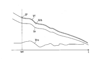
- a point (specific time point) at which the true front and rear wheel speeds Vf and Vr are considered to be the same is defined as an initial point IP.
- the true front and rear wheel speeds Vf and Vr are the same means that the front wheel speed Vf that is the basis of the vehicle speed (vehicle speed) is the same as the rear wheel speed Vr that has been corrected later.
- the front and rear wheel speeds Vf and Vr corresponding to the same vehicle speed may result in apparently different front and rear wheel speeds Vf and Vr. If the true front and rear wheel speeds Vf and Vr in consideration of the difference in the circumferential length of the front and rear tires are the same, the change rates of the wheel speeds are considered to be the same. Therefore, by correcting the front wheel speed Vf, a corrected wheel speed Vrh that can match the front wheel speed Vf is obtained, and the difference between the corrected wheel speed Vrh and the front wheel speed Vf is used for slip determination.
- the rear wheel speed change rate Vrc (t) at each measurement point of the wheel speed is obtained by the following equation 1.
- Rear wheel speed change rate Vrc (t) (Vr (t ⁇ ) ⁇ Vr (t)) / Vr (t) Equation 1 (Vr (t) is the rear wheel speed Vr at each measurement time)
- Time ⁇ is a measurement cycle.
- the timing tm4 at the moment when the vehicle is in a deceleration state and the tire rotation of the front and rear wheels 2 and 12 is stabilized is used as the initial point IP.
- This timing tm4 is a timing at which, for example, a time ⁇ of about 80 to 100 msec has elapsed after the throttle valve is turned off (fully closed). From this timing tm4, the calculation of the corrected wheel speed Vrh is started (wheel speed correction start permission).
- the initial point IP includes a condition that the vehicle body is in an upright state in the roll direction.
- the upright state includes not only an upright position where the left and right center planes of the vehicle body stand vertically, but also a range in which a change in tire circumference during determination is small (a range in which a change in tire curvature is small). For example, it includes a range where the vehicle body is at a bank angle of ⁇ 20 deg from the upright position.
- the initial point IP is detected as a state in which the motorcycle 1 is traveling stably. It should be noted that the circumferential length of the tire contact point changes during the banking of the vehicle body and an inner wheel difference occurs during cornering, so that it is not suitable for determining the front and rear wheel speed difference D.
- a ratio between the front wheel speed Vf and the corrected wheel speed Vrh is calculated as a front-rear wheel speed ratio obtained by correcting the circumferential length difference between the front and rear tires (Equation 4 below), and is used as a determination value for slipper control.
- Front / rear wheel speed ratio Vf (t) / corrected wheel speed Vrh (t) Equation 4
- the “front-rear wheel speed ratio” may be simply referred to as “wheel speed ratio”.
- the condition for allowing (starting) the slipper control during deceleration (half-clutch control) after the start of the wheel speed correction calculation is that the motorcycle 1 is in a rapid deceleration state, and during this rapid deceleration (rear grip force) ⁇ (engine brake).
- all of the following conditions must be satisfied.
- Front wheel speed Vf / corrected wheel speed Vrh (front-rear slip rate)> fourth specified value (reference is 1 (front wheel speed Vf corrected wheel speed Vrh), rear wheel slip increases as front-rear slip rate increases) 3.
- (front-rear slip amount)> first specified value K1 (reference is 0 (front wheel speed Vf corrected wheel speed Vrh), rear wheel slip increases as front-rear slip amount
- the front-rear slip ratio can be equal to or greater than the fourth specified value when (rear grip force) ⁇ (engine brake) and the front-rear wheel speed difference D occurs.
- the front-rear slip ratio is equal to or greater than the fourth specified value, a situation may be required in which slipper control intervention is required.
- the ECU 60 After the vehicle body deceleration has increased from the 0 level to the third specified value K3, if the longitudinal slip rate is at least one of the fourth specified value and the longitudinal slip amount is at least one of the first specified value K1, the ECU 60 counts a timer. To start. When the count exceeds a specified time, slipper control at the time of deceleration is started. By making the control condition continue for a prescribed time, the instantaneous slip and the like are excluded.
- ⁇ Fifth specified value (equivalent to 0, to prevent shock when clutch is engaged)
- the clutch control device 60A of the motorcycle 1 in the first embodiment includes the rear wheel 12, which is a driving wheel, the front wheel 2, which is a driven wheel, the traveling engine 13, and the engine 13 described above.
- An ECU 60 wherein the ECU 60 reduces the clutch capacity when the motorcycle 1 detects that the rear wheel 12 is in a predetermined contact load reduction state (rear lift state) during deceleration of the motorcycle 1. I do.
- the ECU 60 determines that the rear wheel speed Vr, which is the rotation speed of the rear wheel 12, is different from the front wheel speed Vf, which is the rotation speed of the front wheel 2, by a predetermined difference (first specified value K1). ), It is determined that the rear wheel 12 is in the ground contact load reduced state. According to this configuration, it is possible to perform slipper control for reducing the clutch capacity when detecting a decrease in the grounding load that causes the rear wheel 12 to float when the motorcycle 1 decelerates. Thus, it is possible to secure an appropriate engine brake during normal running with the ground load of the rear wheel 12 secured, and to shift to slipper control during rapid deceleration when the rear wheel 12 floats.
- the engine brake of the rear wheel 12 is weakened by the slipper control, the occurrence of hopping and snaking due to the engine brake when the ground load of the rear wheel 12 is released is suppressed. For this reason, it is possible to ensure the rear-wheel contact property of the motorcycle 1 during deceleration. For example, in the racing use of the motorcycle 1, when entering a corner while suddenly decelerating, the rider can easily concentrate on cornering, which can contribute to a transition to smooth acceleration when the corner rises. Further, the clutch capacity can be made variable as compared with a mechanical back torque limiter.
- the ECU 60 uses the corrected wheel speed Vrh obtained by correcting the front wheel speed Vf as the rear wheel speed Vr to be compared with the front wheel speed Vf.
- the actual front and rear wheel speeds Vf and Vr are affected not only by the difference in the tire outer diameter of the front and rear wheels 2 and 12, but also by the change in the circumferential length of the tire.
- a corrected wheel speed Vrh for comparison is calculated based on the front wheel speed Vf, and the corrected wheel speed Vrh is compared with the front wheel speed Vf, thereby being affected by a change in tire circumference. Without this, it is possible to accurately detect a decrease in the rear wheel speed Vr, and to prevent an inadvertent decrease in clutch capacity (a decrease in engine brake).
- the corrected wheel speed Vrh is obtained by adding the change amount of the rear wheel speed Vr at the same time to the front wheel speed Vf at the time of the wheel speed correction.
- the change amount of the rear wheel speed Vr is added to the front wheel speed Vf to correct the wheel speed, so that the correction control can be simplified and the system load can be suppressed.
- the motorcycle 1 In the clutch control device 60A of the motorcycle 1, it is specified that the motorcycle 1 is in the upright posture, the difference between the front and rear wheel speeds Vf and Vr is less than a predetermined predetermined initial value, and the throttle of the engine 13 is closed.
- the wheel speed correction is started from the time point (initial point IP).
- the motorcycle 1 is in the decelerating state in which the throttle of the engine 13 is closed in the upright posture, and the difference between the front and rear wheel speeds Vf and Vr is less than the initial specified value which is set in advance as a value without rear wheel slip.
- wheel speed correction can be performed with high accuracy.
- a value obtained by dividing the front wheel speed Vf by the corrected wheel speed Vrh is set as a first parameter Pa1 (front-rear slip ratio), and the corrected wheel speed is calculated from the front wheel speed Vf.
- a value obtained by subtracting Vrh is defined as a second parameter Pa2 (a longitudinal slip amount), and the slipper control is interposed according to at least one of the first parameter Pa1 and the second parameter Pa2.
- an appropriate value is selected from the two types of parameters, and the slipper control intervention determination (determination that the rear wheel 12 is slipping, in other words, slip determination) is performed, so that the necessary minimum value is obtained.
- the slipper control can be performed at a frequency of.
- the slipper control is interposed according to the first parameter Pa1, and the vehicle speed is lower than the first vehicle speed and the second vehicle speed is lower than the second vehicle speed.
- the slipper control is interposed according to the second parameter Pa2.
- the ECU 60 opens the throttle of the engine 13 in a state where the slipper control is intervened, and cancels the state where the ground contact load of the rear wheel 12 is reduced. , The intervention of the slipper control is released.
- the clutch capacity can be quickly restored from the reduced state to the connected state.
- the deceleration slipper control and the wheel speed correction control of the second embodiment are basically the same as those of the first embodiment.
- the purpose is to realize reliable slipper control intervention during deceleration.
- the second embodiment even when sudden braking of the vehicle is performed in the vehicle body bank state, reliable slipper control intervention during deceleration is realized.
- the effective circumference of the tires of the front and rear wheels 2 and 12 changes under the influence of various factors. For this reason, even when trying to detect the wheel speed, a value different from the actual wheel speed may be detected, making it difficult to detect the occurrence of the wheel speed difference.
- the effective circumference of a tire changes due to differences in default circumference due to differences in tire brand, differences in circumference due to tire wear, and differences in circumference due to tire deformation (air pressure, speed, etc.). I will. Changes in the effective circumference due to the influence of the tires are corrected by executing the wheel speed correction control described above, so that the occurrence of a wheel speed difference can be accurately detected.
- the contact angle between the road surface and the tire changes, so that the effective circumference of the tire changes.
- the wheel speed correction control also becomes difficult. That is, in a region where the bank angle is large, the difference in the change in the effective circumference of the front and rear wheel tires is large, and it is difficult to accurately detect the occurrence of the wheel speed difference.
- the vertical axis of FIG. 10C indicates a value (perimeter change rate ratio) obtained by dividing the change rate of the effective circumference of the front wheel (front wheel change rate) by the change rate of the effective circumference of the rear wheel (rear wheel change rate). .
- the effective circumference of the rear wheels becomes relatively longer as the vehicle body is banked.
- the rotational speed of the rear wheel becomes apparently higher (faster), so that the slip of the rear wheel is hardly detected, and the intervention of the slipper control may be delayed.
- the deceleration of the front wheel speed front wheel deceleration (vehicle speed If the deceleration is greater than or equal to a predetermined value, the slipper control during deceleration is permitted (started).
- a control intervention pattern at the time of sudden deceleration in a vehicle body upright state (a bank angle of less than 20 °) will be described.
- the wheel speed correction control is performed in the area a1 where the load movement of the vehicle has calmed down due to elapse of a predetermined time or the like.
- slipper control during deceleration is interposed.
- the vehicle when entering a cornering in a race or the like, even when sudden deceleration is started in the upright state of the vehicle, the vehicle may be banked to the left or right in the decelerated state (arrows a3 and a4 in the figure).
- the difference in the change in the effective circumference of the front and rear wheel tires is increased, so that the rotational speed of the rear wheel is apparently reduced, and the slipper control during deceleration is intervened earlier.
- it is possible to ensure early contact with the rear wheels when the vehicle body bank is decelerated.
- a control intervention pattern at the time of sudden deceleration in a vehicle bank state (a bank angle of 20 ° or more) will be described with reference to FIG. 11B.
- the wheel speed correction control is performed in the area b1 where the load movement of the vehicle has calmed down due to the lapse of a predetermined time or the like as described above. I do.
- slipper control during deceleration is interposed.
- ⁇ Referring to FIG. 12, even in a bank state in which the vehicle body roll angle (bank angle) is equal to or greater than a predetermined value, when the front wheel speed deceleration exceeds a predetermined value, a wheel speed correction calculation is started (timing tm5). Then, if an increase in the corrected wheel speed ratio (difference) is recognized, slipper control during deceleration is started (timing tm6). Thereafter, when the deceleration of the front wheel speed becomes less than a predetermined value (timing tm7), the calculation of the wheel speed correction and the slipper control during deceleration are ended and the clutch is engaged.
- the throttle opening starts to decrease immediately after the vehicle starts. Shifts from the acceleration state to the deceleration state (timing tm8). At this time, triggered by the closing of the throttle grip, the first timer for waiting for vehicle body stability starts counting. The count of the first timer is reset by opening the throttle grip.
- the second timer for waiting for the vehicle body stabilization starts counting when the deceleration of the vehicle speed reaches a predetermined value or more (timing). tm9). Note that the count of the second timer is reset when the deceleration of the vehicle speed falls below a predetermined value.
- the condition for starting the wheel speed correction calculation in the vehicle body bank state is that all of the following conditions are satisfied. 1. 1. Both timers expire for waiting for vehicle stability. 2. Body bank state Front wheel speed ⁇ predetermined value Front wheel speed deceleration ⁇ predetermined value The wheel speed correction calculation is started at timing tm10 (see FIG. 13) in which these conditions are satisfied.
- the wheel speed correction calculation in the vehicle body bank state ends. 1. 1. Opening the throttle grip Front wheel speed ⁇ predetermined value Front wheel speed deceleration ⁇ predetermined value At time tm11 (see FIG. 13) in which at least one of these conditions is satisfied, the wheel speed correction calculation ends. The calculation is continued even if the vehicle bank angle changes during the wheel speed correction calculation.
- the bank angle increases (deepens) and a case where the bank angle decreases (shallows) based on the bank angle at the start of the wheel speed correction.
- the bank angle becomes deep, the wheel speed ratio tends to increase, so that slipper control is easily performed, and there is no possibility that control is not intervened.
- the bank angle becomes shallow, the wheel speed ratio tends to decrease, so that it is difficult to enter the slipper control, and there is a possibility that control is not intervened.
- the intervention conditions of the slipper control at this time will be described with reference to FIG.
- the slipper control intervention condition is that at least one of the following conditions is satisfied. 1. 1. When front wheel speed ⁇ predetermined value, corrected wheel speed ratio ⁇ predetermined value When front wheel speed ⁇ predetermined value, corrected wheel speed ratio ⁇ predetermined value (for each gear) 3. Deceleration of front wheel speed according to bank angle ⁇ threshold (see FIG. 15) In the example of FIG. 14, in the vehicle body bank state, the corrected wheel speed ratio is less than the predetermined value, but slipper control is interposed at timing tm12 when the deceleration of the front wheel speed reaches the predetermined value.
- the intervention of the slipper control ends. 1. 1. Opening the throttle grip Front wheel speed deceleration ⁇ predetermined value In the example of FIG. 14, the intervention of the slipper control is ended, for example, at timing tm13 when the throttle opening operation is performed.
- FIG. 16 is a control flow when determining whether or not to shift to the wheel speed correction control in the first and second embodiments.
- this control flow whether to perform the wheel speed correction control of the first embodiment or the wheel speed correction control of the second embodiment is divided depending on the bank angle of the vehicle body.
- step S11 it is determined whether or not the vehicle body bank angle is equal to or larger than a predetermined value. If YES in step S11 (the vehicle body bank angle is equal to or more than the predetermined value), the process proceeds to step S12, and it is determined whether the wheel speed correction condition in the vehicle body bank is satisfied.
- the wheel speed correction condition in the vehicle body bank is that the vehicle speed is equal to or higher than a predetermined value, the deceleration is equal to or higher than a predetermined value, and the grip APS opening is equal to or lower than a predetermined value. If YES in step S12 (the wheel speed correction condition is satisfied), the process proceeds to step S13 to perform wheel speed correction control in the vehicle body bank (second embodiment). The wheel speed correction control itself is the same as in the first embodiment. If NO (the wheel speed correction condition is not satisfied) in step S12, the process is temporarily terminated.
- step S11 the vehicle body bank angle is less than the predetermined value
- step S14 determines whether or not the wheel speed correction condition while the vehicle is upright is satisfied.
- the wheel speed correction condition when the vehicle is standing upright is that the vehicle speed is equal to or higher than a predetermined value, the deceleration is equal to or higher than a predetermined value, the grip APS opening is equal to or lower than a predetermined value, and the wheel speed ratio is lower than a predetermined value. , Are all satisfied.
- step S14 the wheel speed correction condition is satisfied
- the process proceeds to step S15, and the wheel speed correction condition while the vehicle is standing upright is performed (first embodiment). If NO in step S14 (the wheel speed correction condition is not satisfied), the process is temporarily terminated.
- FIG. 17 is a control flow when determining whether or not the slipper control is executed in the first and second embodiments.
- the difference between the first embodiment and the second embodiment is whether or not deceleration is considered.
- step S21 it is determined whether or not the wheel speed correction control in the vehicle body bank is being performed (step S21). If YES in step S21 (during wheel speed correction control in the vehicle body bank (second embodiment)), the process shifts to step S22 to determine whether the wheel speed ratio is equal to or higher than a predetermined value. If YES in step S22 (the wheel speed ratio is equal to or more than a predetermined value), the flow shifts to step S23 to perform slipper control in the vehicle body bank. If NO in step S22 (the wheel speed ratio is less than the predetermined value), the process proceeds to step S24 to determine whether the deceleration is equal to or more than a predetermined value.
- step S24 the flow shifts to step S23 to perform slipper control in the vehicle body bank. That is, even if the wheel speed ratio is less than the predetermined value, if the deceleration is equal to or more than the predetermined value, the slipper control is interposed. If NO in step S24 (the deceleration is less than the predetermined value), the process is temporarily terminated.
- step S21 the wheel speed correction control in the vehicle body bank is not being performed
- step S25 it is determined whether the wheel speed correction control is being performed while the vehicle body is standing upright. If YES in step S25 (the wheel speed correction control is being performed while the vehicle is standing upright (first embodiment)), the process proceeds to step S26 to determine whether the wheel speed ratio is equal to or higher than a predetermined value. If YES in step S26 (the wheel speed ratio is equal to or more than a predetermined value), the flow shifts to step S27 to perform slipper control while the vehicle is standing upright. If NO in step S25 (the wheel speed correction control is not being performed while the vehicle is standing upright), and if NO in step S26 (the wheel speed ratio is less than a predetermined value), the process is temporarily terminated.
- FIG. 18 is a control flow when determining whether to end the slipper control in the first and second embodiments. In this control flow, the end condition of the slipper control is different between the first embodiment and the second embodiment.
- step S31 it is determined whether or not the slipper control end condition is satisfied.
- the slipper control termination condition is that at least one of the following conditions is satisfied: the grip APS opening is equal to or more than a predetermined value, and the deceleration is less than a predetermined value. If YES (slipper control end condition is satisfied) in step S31, the process shifts to step S32 to end the slipper control.
- step S31 slipper control end condition is not satisfied
- step S33 determines whether or not the slipper control is being performed while the vehicle is standing upright. If YES in step S33 (during slipper control while the vehicle is standing upright (first embodiment)), the process proceeds to step S34 to determine whether the wheel speed ratio is less than a predetermined value. If YES in step S34 (the wheel speed ratio is less than the predetermined value), the process shifts to step S32 to end the slipper control.
- step S33 the slipper control is not being performed while the vehicle is standing upright (including the second embodiment)
- step S34 the wheel speed ratio is equal to or higher than a predetermined value
- the process is temporarily terminated.
- the second embodiment since the second embodiment includes the execution of the wheel speed correction control in the vehicle body bank, the second embodiment has fewer conditions for ending the slipper control than the first embodiment, Is difficult to finish.
- the clutch control device for the motorcycle 1 when the bank angle of the vehicle body is larger than a predetermined value and the deceleration of the vehicle speed is larger than a predetermined value, the front-rear wheel speed difference is smaller than a predetermined value.
- slipper control during deceleration is intervened. That is, in a region where the bank angle of the vehicle body is large, it is difficult to accurately detect a difference in wheel speed due to different cross-sectional shapes of the tread surfaces of the front and rear wheels.
- the clutch slipper control is performed regardless of the wheel speed difference. As a result, the slipper control is appropriately shifted even when the vehicle is banked, so that the rear-wheel contact property of the motorcycle 1 at the time of deceleration can be ensured.
- the present invention is not limited to the above-described embodiment.
- the operation state of the suspension is detected by a sensor, or the body state is detected by a gyro sensor 49, so that the rear wheel is detected.
- a decrease in the ground contact load of No. 12 may be detected.
- the decrease in the ground contact load of the rear wheel 12 may be detected or the slipper control intervention determination may be performed using the actually measured rear wheel speed Vr.
- the above-mentioned saddle-ride type vehicles include all types of vehicles on which a driver rides across a vehicle body, and include not only motorcycles (including motor-driven bicycles and scooter-type vehicles) but also three wheels (besides one front wheel and two rear wheels). , Including front two-wheel and rear one-wheel vehicles) or four-wheel vehicles and including an electric motor in the prime mover, a vehicle that drives the rear wheels (drive wheels) without a transmission through control of the prime mover, etc. Is also included.
- the configuration in the above embodiment is an example of the present invention, and various changes can be made without departing from the gist of the present invention, such as replacing the component of the embodiment with a known component.
Landscapes
- Engineering & Computer Science (AREA)
- General Engineering & Computer Science (AREA)
- Physics & Mathematics (AREA)
- Fluid Mechanics (AREA)
- Mechanical Engineering (AREA)
- Hydraulic Clutches, Magnetic Clutches, Fluid Clutches, And Fluid Joints (AREA)
- Control Of Vehicle Engines Or Engines For Specific Uses (AREA)
Abstract
La présente invention concerne un dispositif de commande d'embrayage pour un véhicule à selle, le dispositif comprenant une roue arrière (12) constituant une roue motrice, une roue avant (2) constituant une roue menée, un moteur (13) destiné au déplacement, un dispositif d'embrayage (26) destiné à accoupler ou à désaccoupler une transmission d'une force motrice entre le moteur (13) et la roue arrière (12), un actionneur d'embrayage (50) destiné à amener le dispositif d'embrayage (26) à modifier une capacité d'embrayage, et une unité de commande (60) destiné à calculer une valeur cible de commande (pression hydraulique cible) de la capacité d'embrayage. L'unité de commande (60) effectue une commande d'un sabot de freinage afin de réduire la capacité d'embrayage lors de la détection, pendant la décélération du véhicule à selle (1), d'un état prédéfini de diminution de la charge de contact avec le sol de la roue arrière (12).
Priority Applications (2)
| Application Number | Priority Date | Filing Date | Title |
|---|---|---|---|
| JP2020527351A JP7075996B2 (ja) | 2018-06-29 | 2019-06-07 | 鞍乗り型車両のクラッチ制御装置 |
| DE112019003302.6T DE112019003302T5 (de) | 2018-06-29 | 2019-06-07 | Kupplungssteuervorrichtung für ein Fahrzeug des Sattelsitztyps |
Applications Claiming Priority (4)
| Application Number | Priority Date | Filing Date | Title |
|---|---|---|---|
| JP2018-123814 | 2018-06-29 | ||
| JP2018123814 | 2018-06-29 | ||
| JP2018204514 | 2018-10-30 | ||
| JP2018-204514 | 2018-10-30 |
Publications (1)
| Publication Number | Publication Date |
|---|---|
| WO2020003974A1 true WO2020003974A1 (fr) | 2020-01-02 |
Family
ID=68986218
Family Applications (1)
| Application Number | Title | Priority Date | Filing Date |
|---|---|---|---|
| PCT/JP2019/022721 Ceased WO2020003974A1 (fr) | 2018-06-29 | 2019-06-07 | Dispositif de commande d'embrayage pour véhicule à selle |
Country Status (3)
| Country | Link |
|---|---|
| JP (1) | JP7075996B2 (fr) |
| DE (1) | DE112019003302T5 (fr) |
| WO (1) | WO2020003974A1 (fr) |
Cited By (2)
| Publication number | Priority date | Publication date | Assignee | Title |
|---|---|---|---|---|
| WO2020195779A1 (fr) * | 2019-03-27 | 2020-10-01 | 本田技研工業株式会社 | Dispositif de commande d'embrayage pour véhicule de type à selle |
| JP2023050302A (ja) * | 2021-09-30 | 2023-04-11 | 本田技研工業株式会社 | クラッチ制御装置 |
Families Citing this family (3)
| Publication number | Priority date | Publication date | Assignee | Title |
|---|---|---|---|---|
| KR101703441B1 (ko) * | 2015-09-16 | 2017-02-07 | 현대건설주식회사 | 플로팅 도크를 이용한 상향식 프리캐스트 저판형 케이슨 제작방법, 그 시스템, 그 플로팅 도크 및 이를 이용한 케이슨 |
| US11225301B2 (en) * | 2019-12-18 | 2022-01-18 | Honda Motor Co., Ltd. | Providing movement assistance to electric cycle on inclined structures |
| US12152643B2 (en) * | 2021-03-31 | 2024-11-26 | Honda Motor Co., Ltd. | Clutch control device |
Citations (5)
| Publication number | Priority date | Publication date | Assignee | Title |
|---|---|---|---|---|
| JP2009079749A (ja) * | 2007-09-27 | 2009-04-16 | Honda Motor Co Ltd | 鞍乗型車両のクラッチ制御システム |
| JP2009184486A (ja) * | 2008-02-06 | 2009-08-20 | Hitachi Ltd | 二輪車用ブレーキ装置 |
| JP2011520703A (ja) * | 2008-05-26 | 2011-07-21 | ロベルト・ボッシュ・ゲゼルシャフト・ミト・ベシュレンクテル・ハフツング | 自動二輪車の走行運動の安定化方法および装置 |
| JP2012172595A (ja) * | 2011-02-22 | 2012-09-10 | Honda Motor Co Ltd | 自動二輪車の姿勢制御装置及び姿勢制御方法 |
| JP2017187049A (ja) * | 2016-03-31 | 2017-10-12 | 本田技研工業株式会社 | 車両制御装置 |
-
2019
- 2019-06-07 DE DE112019003302.6T patent/DE112019003302T5/de active Pending
- 2019-06-07 WO PCT/JP2019/022721 patent/WO2020003974A1/fr not_active Ceased
- 2019-06-07 JP JP2020527351A patent/JP7075996B2/ja active Active
Patent Citations (5)
| Publication number | Priority date | Publication date | Assignee | Title |
|---|---|---|---|---|
| JP2009079749A (ja) * | 2007-09-27 | 2009-04-16 | Honda Motor Co Ltd | 鞍乗型車両のクラッチ制御システム |
| JP2009184486A (ja) * | 2008-02-06 | 2009-08-20 | Hitachi Ltd | 二輪車用ブレーキ装置 |
| JP2011520703A (ja) * | 2008-05-26 | 2011-07-21 | ロベルト・ボッシュ・ゲゼルシャフト・ミト・ベシュレンクテル・ハフツング | 自動二輪車の走行運動の安定化方法および装置 |
| JP2012172595A (ja) * | 2011-02-22 | 2012-09-10 | Honda Motor Co Ltd | 自動二輪車の姿勢制御装置及び姿勢制御方法 |
| JP2017187049A (ja) * | 2016-03-31 | 2017-10-12 | 本田技研工業株式会社 | 車両制御装置 |
Cited By (5)
| Publication number | Priority date | Publication date | Assignee | Title |
|---|---|---|---|---|
| WO2020195779A1 (fr) * | 2019-03-27 | 2020-10-01 | 本田技研工業株式会社 | Dispositif de commande d'embrayage pour véhicule de type à selle |
| JPWO2020195779A1 (ja) * | 2019-03-27 | 2021-11-11 | 本田技研工業株式会社 | 鞍乗り型車両のクラッチ制御装置 |
| JP7130847B2 (ja) | 2019-03-27 | 2022-09-05 | 本田技研工業株式会社 | 鞍乗り型車両のクラッチ制御装置 |
| JP2023050302A (ja) * | 2021-09-30 | 2023-04-11 | 本田技研工業株式会社 | クラッチ制御装置 |
| JP7798518B2 (ja) | 2021-09-30 | 2026-01-14 | 本田技研工業株式会社 | クラッチ制御装置 |
Also Published As
| Publication number | Publication date |
|---|---|
| JP7075996B2 (ja) | 2022-05-26 |
| JPWO2020003974A1 (ja) | 2021-04-22 |
| DE112019003302T5 (de) | 2021-03-18 |
Similar Documents
| Publication | Publication Date | Title |
|---|---|---|
| JP7075996B2 (ja) | 鞍乗り型車両のクラッチ制御装置 | |
| JP6049772B2 (ja) | 自動二輪車の変速機制御装置 | |
| JP5695496B2 (ja) | 車両のブレーキ制御装置 | |
| KR100986858B1 (ko) | 자동이륜차의 변속 제어 장치 | |
| JP5041974B2 (ja) | 制御システムおよび車両 | |
| JP2015214959A (ja) | エンジン制御装置 | |
| JP5386273B2 (ja) | 鞍乗型乗物用エンジン制御装置 | |
| JP7112594B2 (ja) | クラッチ制御装置 | |
| JP7064874B2 (ja) | クラッチ制御装置およびクラッチ制御システム | |
| JP6756043B2 (ja) | 車両用変速システム | |
| JP2014035066A (ja) | 自動変速装置およびそれを備えた鞍乗型車両 | |
| JP7106745B2 (ja) | クラッチ制御装置 | |
| JP7059442B2 (ja) | 鞍乗り型車両のクラッチ制御装置およびクラッチ制御方法 | |
| JP2023050550A (ja) | 車両 | |
| JP6845948B2 (ja) | 変速装置 | |
| JP7163483B2 (ja) | 鞍乗り型車両のクラッチ制御装置 | |
| JP2024120561A (ja) | 車両の制御装置および車両の制御方法 | |
| JP4873543B2 (ja) | 自動変速制御装置および車両 | |
| JPWO2019087511A1 (ja) | クラッチ制御装置 | |
| JPWO2019087512A1 (ja) | クラッチ制御装置 | |
| JP7130847B2 (ja) | 鞍乗り型車両のクラッチ制御装置 | |
| WO2020066869A1 (fr) | Dispositif de commande d'embrayage | |
| JP5214769B2 (ja) | 自動変速制御装置および車両 | |
| JP2023050302A (ja) | クラッチ制御装置 | |
| JPWO2020195831A1 (ja) | 鞍乗り型車両のクラッチ制御装置およびクラッチ制御方法 |
Legal Events
| Date | Code | Title | Description |
|---|---|---|---|
| 121 | Ep: the epo has been informed by wipo that ep was designated in this application |
Ref document number: 19825944 Country of ref document: EP Kind code of ref document: A1 |
|
| ENP | Entry into the national phase |
Ref document number: 2020527351 Country of ref document: JP Kind code of ref document: A |
|
| 122 | Ep: pct application non-entry in european phase |
Ref document number: 19825944 Country of ref document: EP Kind code of ref document: A1 |