WO2020004033A1 - Dispositif de traitement d'informations, procédé de traitement d'informations et programme - Google Patents
Dispositif de traitement d'informations, procédé de traitement d'informations et programme Download PDFInfo
- Publication number
- WO2020004033A1 WO2020004033A1 PCT/JP2019/023249 JP2019023249W WO2020004033A1 WO 2020004033 A1 WO2020004033 A1 WO 2020004033A1 JP 2019023249 W JP2019023249 W JP 2019023249W WO 2020004033 A1 WO2020004033 A1 WO 2020004033A1
- Authority
- WO
- WIPO (PCT)
- Prior art keywords
- sensor
- gateway
- server
- data
- sensing data
- Prior art date
- Legal status (The legal status is an assumption and is not a legal conclusion. Google has not performed a legal analysis and makes no representation as to the accuracy of the status listed.)
- Ceased
Links
Images


Classifications
-
- H—ELECTRICITY
- H04—ELECTRIC COMMUNICATION TECHNIQUE
- H04Q—SELECTING
- H04Q9/00—Arrangements in telecontrol or telemetry systems for selectively calling a substation from a main station, in which substation desired apparatus is selected for applying a control signal thereto or for obtaining measured values therefrom
-
- H—ELECTRICITY
- H04—ELECTRIC COMMUNICATION TECHNIQUE
- H04W—WIRELESS COMMUNICATION NETWORKS
- H04W72/00—Local resource management
- H04W72/30—Resource management for broadcast services
-
- H—ELECTRICITY
- H04—ELECTRIC COMMUNICATION TECHNIQUE
- H04W—WIRELESS COMMUNICATION NETWORKS
- H04W4/00—Services specially adapted for wireless communication networks; Facilities therefor
- H04W4/06—Selective distribution of broadcast services, e.g. multimedia broadcast multicast service [MBMS]; Services to user groups; One-way selective calling services
-
- H—ELECTRICITY
- H04—ELECTRIC COMMUNICATION TECHNIQUE
- H04W—WIRELESS COMMUNICATION NETWORKS
- H04W72/00—Local resource management
- H04W72/50—Allocation or scheduling criteria for wireless resources
- H04W72/52—Allocation or scheduling criteria for wireless resources based on load
-
- H—ELECTRICITY
- H04—ELECTRIC COMMUNICATION TECHNIQUE
- H04M—TELEPHONIC COMMUNICATION
- H04M11/00—Telephonic communication systems specially adapted for combination with other electrical systems
- H04M11/04—Telephonic communication systems specially adapted for combination with other electrical systems with alarm systems, e.g. fire, police or burglar alarm systems
-
- H—ELECTRICITY
- H04—ELECTRIC COMMUNICATION TECHNIQUE
- H04Q—SELECTING
- H04Q2209/00—Arrangements in telecontrol or telemetry systems
- H04Q2209/40—Arrangements in telecontrol or telemetry systems using a wireless architecture
-
- H—ELECTRICITY
- H04—ELECTRIC COMMUNICATION TECHNIQUE
- H04Q—SELECTING
- H04Q2213/00—Indexing scheme relating to selecting arrangements in general and for multiplex systems
- H04Q2213/13092—Scanning of subscriber lines, monitoring
Definitions
- the present technology relates to an information processing device, an information processing method, and a program.
- Patent Document 1 describes a so-called “event-driven” process in which image data is sent from an in-vehicle device to a server when an event such as an accident occurs.
- Patent Documents 2 and 3 describe, in the technical field of a proxy server, a proxy server that performs high-speed access to a cache by using a hash index.
- IoT Internet of Things
- An object of the present technology made in view of the above circumstances is to provide an information processing apparatus, an information processing method, and a program that dynamically optimize data collection in response to a network load.
- the information processing device is configured to communicate with a server and a sensor via a network.
- the information processing device includes a communication unit and a control unit.
- the communication unit transmits setting parameters of the sensor to the sensor, receives sensing data of the sensor sensed based on the setting parameters, and transmits the sensing data to the server.
- the control unit determines whether the sensing data needs to be processed before transmitting the sensing data received from the sensor to the server.
- the information processing device as an intermediate node in the system including the server, the information processing device, and the sensor determines whether the processing of the sensing data is necessary, and the load on the processing of the sensing data is concentrated on the server. Therefore, data collection can be optimized in response to the network load dynamically.
- control unit may determine whether or not processing before transmitting the sensing data to the server is necessary in accordance with the sensing data.
- sensing data based on information and conditions (including, but not limited to, information such as outside air temperature and radio field intensity and situations such as occurrence of a traffic accident) according to the sensing data are performed. Since the necessity of the processing is determined, the accuracy of the sensing data does not decrease in an important situation.
- the communication unit may transmit the setting parameter for initial setting or resetting to the sensor when receiving the connection request from the sensor.
- the information processing apparatus transmits a setting parameter to the sensor at a reception timing of a connection request such as a handover from the sensor, so that smooth information collection is promoted.
- the senor may include a plurality of sensors, and the control unit may update the setting parameter according to a change in the number or density of a plurality of moving objects on which the sensors are installed. You may.
- the communication unit is configured to select a method of transmitting the setting parameter to the sensor from at least a transmission method including a unicast method and a broadcast method according to the type of the setting parameter. There may be.
- the control unit when the control unit processes the sensing data, the control unit may compress the sensing data using a hash function.
- Another aspect of the present technology to achieve the above object is to configure an information processing device to mutually communicate with a server and a sensor via a network, transmit a setting parameter of the sensor to the sensor, and An information processing method comprising: receiving sensing data of the sensor sensed based on the sensor, determining whether or not to process the sensing data received from the sensor, and transmitting the sensing data to the server.
- Another aspect of the present technology that achieves the above object is a step of configuring the computer to communicate with a server and a sensor via a network via a network, and transmitting a setting parameter of the sensor to the sensor.
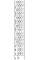
- FIG. 1 is a conceptual diagram of a network configuration of a system according to a first embodiment. It is a configuration example of a gateway and the like included in the system according to the embodiment. It is a figure for explaining the outline of the whole operation of the above-mentioned embodiment. It is a figure (the 1) for explaining the setting phase in the above-mentioned embodiment. It is a figure for explaining collection data in the above-mentioned embodiment. It is a figure for explaining collection frequency in the above-mentioned embodiment.
- FIG. 8 is a diagram (part 2) for describing a setting phase in the embodiment. It is an example (server) of the processing procedure of the parameter setting of the said embodiment.
- FIG. 11 is a diagram for describing an outline of an overall operation according to the second embodiment. It is an example of a processing procedure of the sensor in the embodiment. It is a processing procedure example of the gateway in the said embodiment. It is an example of a processing procedure of the server in the embodiment. It is a figure for explaining an outline of the whole operation of a 3rd embodiment. It is an example of a processing procedure of the sensor in the embodiment. It is a processing procedure example of the gateway in the said embodiment. It is an example of a processing procedure of the server in the embodiment. It is FIG. (1) for demonstrating the setting phase in 4th Embodiment.
- FIG. 8 is a diagram (part 2) for describing a setting phase in the embodiment. It is an example of the processing procedure of the gateway in 5th Embodiment.
- First embodiment 1.1. Overall system 1.2. Configuration of server, gateway, and sensor 1.3. Description of overall operation 1.4. Setting Phase 1.4.1. Overview of setting phase 1.4.2. Details of setting phase 1.5. Operation Phase 1.5.1. Sensor data collection process 1.5.2. Gateway data collection process 1.5.3. Server data collection process 1.6. Use phase2. Second embodiment 3. Third embodiment 4. Fourth embodiment 5. Fifth embodiment 6. Other Embodiment 7 Note
- an IoT device in an IoT system is shown as an example of a sensor, and a vehicle-mounted sensor (vehicle-mounted device) is shown as an example of the IoT device.
- the sensor is not limited to this example.
- a base station hereinafter, mainly referred to as a “gateway” in a wireless data communication system is shown as an example of an information processing device, but the information processing device is not limited to this example.
- a so-called cloud server physically constituted by a plurality of server groups is shown as an example of a server, but the server is not limited to this example.
- states of various wireless communication environments (such as radio wave intensity) of the in-vehicle device are assumed, but the present technology is not limited to this example.
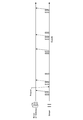
- FIG. 1 there is shown a conceptual diagram of a configuration of an overall system according to the present embodiment. As shown in FIG. 1, the entire system 1 includes a server 300, a plurality of gateways 200, and a plurality of sensors 100.
- the network N is configured to be able to communicate between the cloud (server 300) and the gateway 200, between the gateway 200 and the sensor 100, and between the cloud (server 300) and the sensor 100.
- the gateway 200 may have the function of the sensor 100.
- Network N is a generic name of the network of the present embodiment including the network N1 and the network N2.
- the physical layer and data link layer of the network N are not limited.
- a mobile phone communication network including an MNO (Mobile Network Operator) network, an MVNO (Mobile Virtual Network Operator) network), a network based on various wireless local area network standards, a short-range wireless communication (Bluetooth (registered) Trademark) can be used as the network of the present embodiment.
- a wide area network, a business network, a private network, or the like can be used as the network N.
- the gateway 200 has the same configuration as a general-purpose computer. That is, the gateway 200 includes a CPU (Central Processing Unit) 11, a ROM (Read Only Memory) 12, a RAM (Random Access Memory) 13, an input / output interface 15, and a bus 14 for connecting these to each other.
- a CPU Central Processing Unit
- ROM Read Only Memory
- RAM Random Access Memory
- the CPU 11 accesses the RAM 13 and the like as needed, and controls the entire block as a whole while performing various arithmetic processes.
- the ROM 12 is a non-volatile memory in which an OS (Operating System) executed by the CPU 11 and firmware such as programs and various parameters are fixedly stored.
- the RAM 13 is used as a work area for the CPU 11 and temporarily stores an OS, various applications being executed, and various data being processed.
- the CPU 11 loads a software program stored in the ROM 12 to configure a control unit of the apparatus.
- the display unit 16, the operation receiving unit 17, the storage unit 18, the communication unit 19, and the like are connected to the input / output interface 15.
- the display unit 16 is a display device using, for example, an LCD (Liquid Crystal Display), an OELD (Organic Electro-Luminescence Display), a CRT (Cathode Ray Tube), or the like.
- the operation receiving unit 17 is, for example, a pointing device such as a mouse, a keyboard, and other input devices.
- the display unit 16 and the operation receiving unit 17 may be integrated by a liquid crystal touch panel.
- the storage unit 18 is a non-volatile memory such as a hard disk drive (HDD), a solid state drive (SSD), and other solid-state memories.
- the storage unit 18 stores the OS, various applications, and various data.
- the communication unit 19 is various modules for wireless communication such as a NIC (Network Interface Card) and a wireless LAN.
- the communication unit 19 enables transmission and reception of data with another device of the present apparatus.
- the configuration shown in FIG. 2A is an example of the configuration of the gateway 200, and other elements may be added or some of them may be omitted.
- the server 300 and the sensor 100 may have the same configuration as the gateway 200. Other components may be added to the configuration of the server 300 and the sensor 100, or some of them may be omitted.
- FIG. 2B shows a configuration example of the sensor 100. Description of the parts common to FIG. 2A is omitted.
- the sensor 100 has a sensor unit 20 and a sensor unit 21. In this case, the sensor 100 capable of storing two types of sensing data is illustrated. Specific examples of the sensor unit 20 and the sensor unit 21 include, for example, a camera, a human sensor, and an antenna capable of evaluating the radio wave intensity and radio wave quality of wireless communication. However, this example does not limit the sensor 100.
- the plurality of gateways 200 are intermediate nodes located between the sensor 100 and the server 300, and have a multi-layer structure in which any one of the gateways 200 is located above another gateway 200. May be done.
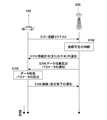
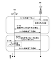
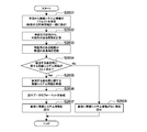
- the server 300 makes settings for the gateway 200 (1-1 in FIG. 3).
- the gateway 200 makes settings for the sensor 100 based on the settings made for the gateway 200 by the server 300 (1-2 in FIG. 3). This is the setting phase.
- the sensor 100 transmits the sensed information to the gateway 200.
- the gateway 200 collects information from the sensor 100 (2-1 in FIG. 3).
- the gateway 200 transmits the collected information or information obtained by processing the collected information to the server 300.
- the server 300 collects information from the gateway 200 (2-2 in FIG. 3). This is the operation phase.
- the server 300 performs analysis and the like based on the collected information and feeds it back to the resetting and control of the gateway 200 and the sensor 100 (3 and 4 in FIG. 3). This is the utilization phase.
- the setting of the sensor 100 may use the information on the setting transmitted from the server 300 to the gateway 200 as it is, or may be generated based on the setting received by the gateway 200 from the server 300.
- the setting parameters of the sensor 100 are provided from the server 300 in common.
- the server 300 directly sets the sensor 100 and that information is directly transmitted from the sensor 100 to the server 300. .
- Sensing data of the sensor 100 and the like are mostly handled in the application layer.
- the application layer only End-to-End is defined, and a node in the middle (intermediate node) is usually transparent.
- the gateway 200 which is an intermediate node, collects and processes sensing data of the sensor 100 in the operation phase.
- the gateway 200 reduces the network load.
- the base station that is the boundary between the wireless network and the wired network according to the present embodiment is used in consideration of the fact that the sensing data has high location dependency.
- the gateway 200 is advantageous, but is not limited to this configuration.
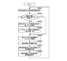
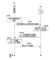
- Setting Phase 1.4.1. Overview of Setting Phase The setting phase is divided into two stages, a setting process from the server 300 to the gateway 200 and a setting process from the gateway 200 to the sensor 100.
- the server 300 sets to the sensor 100 which data items the sensor 100 should transmit to the server 300, in what manner (processing, no processing, etc.) and at what frequency. Is set for the gateway 200 of the intermediate node. This makes it possible to optimize data collection even when the network load fluctuates, such as when the number of sensors 100 increases.
- the server 300 sets the data items to be collected from the sensor 100 and the frequency for the gateway 200.
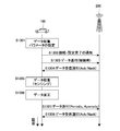
- the gateway 200 notifies the server 300 of its own location information (S401).
- the server 300 determines parameters for the gateway 200 that has notified the location information (S402).
- a notification of the parameter determined by the server 300, in this example, the data collection setting is sent (S403).
- the gateway 200 sets the data collection parameters for its own device (S404).
- the gateway 200 notifies the server 300 of the completion of the setting (S405).
- the server 300 specifies data pre-processing in the gateway 200 (base station) according to the data item of the collected data.
- the pre-processing include an averaging process, a compression process, and a combining process.
- the averaging process includes a process of averaging the collected data for each terminal and a process of averaging over the entire base station area beyond the terminal.
- the compression processing includes lossless compression and lossy compression.
- Lossy compression includes compression using a one-way hash function. In the present embodiment, compression is performed using a one-way hash function.
- the combining process includes a process of combining a plurality of collected data or compressed data into one or a small number of bundles.
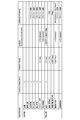
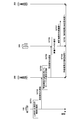
- FIG. 5 shows an outline of data items collected by the system 1. Shown here is an outline, which may be finer data items. Further, the data items are not limited to those illustrated in FIG.
- FIG. 6 is an explanatory diagram of the collection frequency shown in FIG.
- the data collected by the system 1, that is, the data collected by the server 300 includes information on the sensor 100 itself, processed data, and raw data.
- these collected data there are sufficient data to be collected only once when the sensor 100 is initially attached to the network N of the system 1, data to be collected periodically, and data to be collected non-periodically. is there.
- the period of data collected periodically may be divided into multiple stages such as short-term and long-term.
- the data collected non-periodically includes sensing data having a large data amount such as a moving image.
- the periodically collected data is sent from the sensor 100 to the server 300 as shown by a solid arrow in FIG.
- the data collected aperiodically is sent from the sensor 100 to the server 300 when there is a request from the server 300 or when the sensor 100 detects the occurrence of an event, as indicated by a dashed arrow in FIG.
- the gateway 200 notifies the sensor 100 that has made the connection request of the setting parameter for data collection specified by the server 300.
- the gateway 200 may perform additional data collection settings in addition to the settings specified by the server 300.
- a setting contrary to the specification from the server 300 is not permitted. If the sensor 100 has already received the setting parameter once, the sensor 100 uses the setting parameter notified by the gateway 200 as the setting parameter for resetting.
- the sensor 100 requests connection to the gateway 200 as an initial attach to a network, such as when the power is turned on or when a communication function is turned on, when a certain gateway (base station) is connected to another gateway (base station). Station), or when moving from outside the service area to the service area.
- the occurrence of the handover mentioned here includes the start of the handover, the execution of the handover, and the completion of the handover. Since the gateway 200 transmits the setting parameter to the sensor 100 at the timing of receiving the connection request from the sensor 100, smooth information collection is promoted.
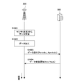
- the sensor 100 makes a connection request to the gateway 200 (S701).
- it is determined whether the gateway 200 permits the connection request (S702).
- the gateway 200 notifies the sensor 100 that has made the connection request of connection permission or non-permission (S703). Here, it is assumed that permission has been granted.
- the gateway 200 notifies the sensor 100 of the data collection setting parameter (S704).
- the sensor 100 sets data collection parameters for the own device (S705).
- the sensor 100 notifies the gateway 200 of the connection and the setting completion (S706).
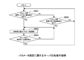
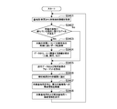
- FIGS. 8, 9 and 10 show examples of processing procedures of the CPU 11 as a control unit of each of the server 300, the gateway 200, and the sensor 100 regarding parameter setting.
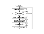
- the server 300 first checks whether there is a gateway 200 (base station) for which no parameter is set (S801). Even when there is no such gateway 200, the server 300 checks whether or not there is a gateway 200 (base station) whose parameter should be changed (S802). If any one of such gateways 200 exists, the server 300 notifies the gateway 200 of the setting parameters (S803). If the setting completion packet is included in the setting parameter packet or the like, the process of the server 300 ends (S804).
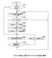
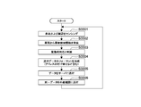
- the gateway 200 first checks whether or not the parameters of its own device have not been set (S901). If the parameters of the own device have been set (S901, No), the movement distance of the own device is detected (S907, described later).
- the gateway 200 If the parameters of the own device are not set (S901, Yes), the gateway 200 notifies the server 300 of the position information and the mobility information of the own device (S902). Subsequently, the gateway 200 confirms whether or not there is a parameter designation by the notification of the setting parameter from the server 300 as described in S803 of FIG. 8 (S903).
- the gateway 200 changes the setting parameter to the specified parameter (S904).
- the server 300 is notified of the setting completion (S905).
- the sensor 100 vehicle is notified of the parameter change (S906).
- the gateway 200 detects the moving distance and the like of the gateway 200 (own apparatus) (S907).
- the gateway 200 determines whether or not the moving distance or the like detected in S907 has exceeded a predetermined threshold (S908).
- the gateway 200 notifies the server 300 of new position information and the like of the gateway 200 (own apparatus) (S902).
- the gateway 200 continues to use the setting parameters specified by the server 300 (S909), and thereafter, the moving distance and the like. Is detected (S907), and the detected moving distance and the like are compared with the threshold (S908).
- the moving distance and the like in FIG. 9 include a position, a connected base station, a change in speed and acceleration, and the like.
- the predetermined threshold value in FIG. 9 is an absolute amount such as a detected moving distance, but in another embodiment, the relative change amount (difference) of the moving distance or the like is different. It may be a predetermined threshold.
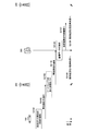
- the sensor 100 first determines whether to connect (including reconnection) to the gateway 200 (base station) (S1001). Next, the sensor 100 notifies the gateway 200 of a connection request (S1002). Next, the sensor 100 determines whether or not a parameter has been designated from the server 300, and if a parameter has been designated, the sensor 100 changes the setting parameter to the designated parameter (S104). Next, the sensor 10 notifies the gateway 200, which is a base station, of the completion of the setting (S105).
- the sensor 100 checks whether the parameter specified by the current (after connection) gateway 200 has been set (S1006). If it has been set, the current parameter is used continuously (S1007). If not set, the current parameter is reset (S1008). The sensor 100 waits for the next parameter designation from the server 300 in any of the parameter setting (S1005), the continuous use of the parameter (S1007), and the parameter reset (S1008) (S1003).
- the sensor 100 When the sensor 100 resets the data collection parameters (S1008), the sensor 100 stops sending data to the gateway 200 (or the server 300). However, even in this case, the sensor 100 may continue collecting (such as sensing) data internally.
- Operation Phase 1.5.1. Sensor Data Collection Process The operation phase is divided into two stages: a data collection process from the sensor 100 to the gateway 200, and a data collection process from the gateway 200 to the server 300.
- the process of collecting data from the sensor 100 to the gateway 200 is divided into a process of establishing a connection (first stage) and a process of sensing and sending data (second stage).
- the sensor 100 in the first stage of the process of collecting data from the sensor 100 to the gateway 200, the sensor 100 establishes a connection with the gateway 200.
- the sensor 100 issues a connection request to the gateway 200 (S1101).
- the gateway 200 determines whether to permit connection to the sensor 100 that has issued the connection request (S1102).
- the gateway 200 notifies the sensor 100 of the determination result of the connection possibility (S1103). In this example, the connection is permitted, and the sensor 100 notifies the gateway 200 of the completion of the connection (S1104).
- the gateway 200 When the connection with the sensor 100 is established, the gateway 200 notifies the data collection setting parameters subsequently (S1105). This notification may be performed by a method of broadcasting to all the sensors 100 connected to the gateway 200 (S1105). Next, the sensor 100 sets the parameters for data collection notified from the gateway 200 to its own device (S1106). Further, the sensor 100 notifies the gateway 200 of the setting completion (S1107).
- the gateway 200 sets the setting parameters for each sensor 100 that has issued the connection request in S1105 (or the sensor 100 that has issued the connection request and has been permitted to connect). Send. That is, the gateway 200 transmits the setting parameters to the sensor 100 in a unicast system. When the gateway 200 transmits the setting parameters to the sensor 100 by the unicast method, the setting parameters suitable for the state and environment of each sensor 100 are applied to the sensor 100. When transmitting the setting parameter to the sensor 100, the gateway 200 transmits only the difference from the previously transmitted setting parameter to the sensor 100. Since the gateway 200 transmits only the difference, the amount of data flowing on the network can be suppressed.
- the gateway 200 may collectively notify the data collection parameters to the plurality of sensors 100 within the communication range of the gateway 200 in S1105. That is, the gateway 200 may transmit the setting parameters to the plurality of sensors 100 in a broadcast (or multicast, group cast) method. When the gateway 200 transmits the setting parameters to the sensors 100 by a broadcast method or the like, the setting parameters can be notified to a large number of sensors 100 by a small number of communication such as one time. The gateway 200 may notify the setting parameters periodically (for example, once every 10 minutes) by a broadcast method or the like regardless of the establishment of the connection with the sensor 100 (S1101 to S1104).
- the gateway 200 Since the setting parameters transmitted to the sensor 100 are a set of parameters including a plurality of setting parameters, the gateway 200 changes some of the setting parameters to the sensor 100 (or the connection request) that issued the connection request. Is issued and the connection is notified for each sensor 100), and another part of setting parameters such as the remaining setting parameters are collectively notified to a plurality of sensors 100 within the communication range of the gateway 200. You may.
- the gateway 200 transmits the setting parameters according to the type of the setting parameters.
- the communication system is selected from communication systems such as unicast, broadcast, multicast, and group cast.
- the gateway 200 transmits, for example, a setting parameter for collecting data such as a personal state of a driver of a moving object (vehicle or the like) by a unicast method transmitted for each sensor 100.
- the gateway 200 transmits a setting parameter for collecting data such as environmental information centered on the gateway 200 by a broadcast method which is transmitted to the sensors 100 under the gateway 200 at the same time.
- the communication unit 19 (or the CPU 11) of the gateway 200 transmits the setting parameters of the type to apply the individual setting to each sensor 100 to the sensor 100 by the unicast method, and sets the same setting to the unspecified number of sensors 100.
- a setting parameter of a type to which is applied to the sensor 100 by a broadcast method flexible distribution of the setting parameter becomes possible. Therefore, according to this configuration, it is possible to dynamically respond to a change in the load of the network or the server.
- FIG. 12 shows a specific example of sensing data (collected data) transmitted from the sensor 100 to the gateway 200.
- sensing data collected data
- the sensor 100 in the case where the sensor 100 is installed on a moving body such as a vehicle as in the present embodiment, for example, data on the state inside the vehicle (such as the number of occupants) and the state outside the vehicle (position data, speed, etc.) Data related to mobility, wireless communication environment, etc.) can be cited as sensing data.
- data items to be sent from the sensor 100 to the gateway 200, timing, additional processing, and the like are designated by setting parameters transmitted from the gateway 200 to the sensor 100.
- the timings that can be set include the time of network attachment, periodic, aperiodic, and the like.
- the sending timing in FIG. 12 is the sending timing set by the setting parameter, and the data collection itself may be performed at a more frequent timing.
- the data collection period is equal to or shorter than the setting in FIG. 12 (data transmission period ⁇ data sensing period), or the data collection frequency is equal or higher (data transmission period). (Frequency ⁇ data sensing frequency) is desirable.
- the sensor 100 performs data collection (sensing) and data transmission according to the setting parameters set in the setting phase.
- the sensor 100 performs data collection (sensing) (S1301). At this time, the sensor 100 re-applies the setting parameters to its own device as needed (S1301). Next, the sensor 100 connects to the gateway 200 and notifies the completion of the setting (S1302). Next, the sensor 100 sends the collected data (sensing data) to the gateway 200 (S1303). Next, the gateway 200 notifies the reception of the sensing data (S1304). This notification is performed irrespective of whether the reception is successful (Ack) or unsuccessful (Nack).
- the above processing in FIG. 13 is the case where the sensor 100 sends the sensing data simultaneously with the connection to the gateway 200.
- ⁇ ⁇ ⁇ Data may be processed in the vehicle between data collection (sensing) and data transmission.
- data processing include time averaging of collected data, coding of collected moving images, privacy protection (mosaicing a person), and the like.
- the sensor 100 When the sensor 100 processes (compresses, etc.) the sensing data in its own device, the sensor 100 performs data processing after collecting data (S1305) and then performs data processing (S1306). Subsequent processing (S1307, 1308) is the same as S1303, S1304.
- the sensor 100 discards the data collected so far when the setting parameters of the data collection change during the data collection or before the data transmission (between S1301 and S1303). It may be.
- FIG. 14 shows an example of a data collection processing procedure (sensor 100).
- the sensor 100 executes a series of handover processes (S1402), and changes the parameters of the sensor 100 (self apparatus) based on the setting parameters received from the gateway 200 newly connected by the handover. It is set (S1403).
- the setting parameters of the sensor 100 (own device) are updated at the timing of handover occurrence (including start of handover, execution of handover, completion of handover) caused by the movement of the sensor 100 installed in the moving body (vehicle, etc.).
- the sensor 100 can collect information using appropriate setting parameters immediately after entering the area where communication with the gateway 200 is valid.
- the sensor 100 skips the handover process and sets the parameters of the own device based on the setting parameters received from the gateway 200 (S1403).
- the sensor 100 determines whether the connection to the gateway 200 for the first time, that is, the transmission of data to be performed when the gateway 200 is initially attached, has been performed (S1404).
- the data transmitted when the sensor 100 first connects to the gateway 200 includes static information of the sensor 100 (own device) such as the specifications of the CPU 11 and the RAM 13 and the firmware version, the temperature of the CPU 11, the usage rate of the RAM 13, and the like. , Information about the environment of the sensor 100 (own device), such as dynamic information of the sensor 100 (own device) and sensing data. If the data to be transmitted at the time of the first connection to the gateway 200 has not been transmitted (S1404, No), the sensor 100 transmits the data to the gateway 200 (S1405).
- the sensor 100 determines whether the setting parameters distributed and transmitted by the gateway 200 have changed (S1406). Since the gateway 200 notifies the sensor 100 that the setting parameter has changed, the sensor 100 determines whether or not the setting parameter has changed based on the notification from the gateway 200. If the setting parameters have been changed (S1406, Yes), the sensor 100 discards the collected data that has not been sent to the gateway 200 yet (S1407), performs handover if necessary (S1402), and resets the parameters. (S1403).
- the sensor 100 collects (senses) data of the data items scheduled to be sent (S1408). Next, the sensor 100 continues sensing until the data transmission timing comes (S1409). When the data transmission timing has come (S1409, Yes), the sensor 100 determines whether to process the sensing data before data transmission (S1410). When processing the sensing data (S1410, Yes), the sensor 100 processes the collected sensing data (S1411). On the other hand, when the sensing data is not to be processed (S1410, No), the sensor 100 skips the processing of the collected sensing data.
- the sensor 100 checks whether or not a wireless resource for data transmission is allocated (S1412). If not (S1412, No), the sensor 100 requests the gateway 200 to allocate a wireless resource (S1412, No). S1413).
- the sensor 100 forms the format of the data to be sent (S1414), and sends the data to the gateway 200 using the allocated wireless resources (S1415).
- FIG. 15 shows an example of the data format formed in S1414. As shown in FIG. 15, the format of data sent from the sensor 100 is divided into a header and a payload, and a bundle of a plurality of (including a plurality of types) collected data can be stored.
- the sensor 100 downloads the setting parameters from the gateway 200 every time a handover occurs. Apply to your own device.
- the gateway 200 transmits the setting parameters in response to the setting parameter download request from the handover sensor 100.
- the gateway 200 may transmit the setting parameters using the handover occurrence information as an occurrence event.
- the detailed process of the process related to the transmission of the setting parameter is as described in the setting phase.
- Gateway Data Collection Process As shown in FIG. 16, in the data collection process from the gateway 200 to the server 300, the gateway 200 performs data transmission according to the setting parameters set from the server 300.
- the gateway 200 receives the sensing data from the sensor 100 (vehicle) (S1601), and processes the received data as needed (S1602). Next, the gateway 200 transmits the processed data (or non-processed data) to the server 300 at various timings such as periodic and aperiodic (S1603). Upon receiving this, the server 300 returns a data reception notification to the gateway 200 (S1604).
- the gateway 200 itself may perform data collection (sensing). In this case, the gateway 200 also has the function of the sensor 100.
- data processing is not indispensable, and the gateway 200 determines whether or not to perform data processing.
- data processing include, for example, data averaging, compression, and combination.
- the gateway 200 discriminates between data that is processed as data for each vehicle and data that is subjected to averaging processing in the base station coverage. I do.
- FIG. 17 shows data items with distinctions. As shown in FIG. 17, the gateway 200 specifies data items to be sent from the gateway 200 to the server 300, timing, additional processing, and the like.
- the gateway 200 compresses the data.
- compression using a one-way hash function may be performed.
- a hash value output obtained by inputting sensing data to the one-way hash function is data that is actually collected (transmitted or received).
- it is not necessary to collect the sensing data itself before compression (only the hash value may be collected).
- the gateway 200 performs compression using a one-way hash function as an example of processing, and a detailed data collection process of the gateway 200 will be described.
- compression using a one-way hash function is adopted as a solution.
- the loads on the devices and the cloud are reduced, and the traffic in the wireless section is reduced.
- a hash tree (hash tree) is constructed in the entire system 1 or a part of the system 1.
- the hash tree is generated for each gateway 200 (base station).
- the data collected by the sensor 100 is highly dependent on the location. Therefore, when the hash tree is generated for each gateway 200 (base station), that is, for each location, usability when using data is higher than when the hash tree is not generated for each location.
- the gateway 200 (base station) adds a header to the hash tree, and describes the information (position information) of the gateway 200 (base station) that has performed compression in the header.
- FIG. 18 shows an example of the hash tree. As illustrated, in each of the gateways 200 and the sensors 100, compression using a one-way hash function is performed again on the hash obtained by combining the hashes compressed in the subordinate gateway 200 or the sensor 100. A hash tree as shown in FIG. 18 is constructed.
- FIG. 18 shows an example of a hash data format.
- FIG. 20 is an example of a processing procedure of a data collection process of the gateway 200.
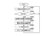
- the gateway 200 first checks whether or not the setting parameters distributed by the server 300 have been changed (S2001). When the setting parameter has been changed (S2001, Yes), the gateway 200 prepares to send the data received and accumulated from the sensor 100 up to this point (S2002).
- the gateway 200 receives data from the sensor 100 (vehicle) (S2003). Next, the gateway 200 accumulates the data (S2004), and waits for a timing for sending the accumulated data to the server 300 (S2005). Next, when the data transmission timing comes (S2005, Yes), the gateway 200 determines whether or not to process the data (excluding compression by a hash function) (S2006).
- the gateway 200 determines the necessity of the data processing (S2006) based on, first, the sensing data of the sensor 100 and, second, the data collection setting parameters set in the sensor 100 in the setting phase. .
- the gateway 200 determines what event (hereinafter, “occurrence event”) has occurred in the system 1 based on the sensing data of the sensor 100, and based on the determined occurrence event. Determine whether data processing is necessary.
- the events that occur include all events sensed by the sensor 100, and specifically include detection of an accident, movement of the sensor 100 (and a vehicle such as a vehicle on which it is installed), and occurrence of handover of the vehicle (handover). , Starting a handover, and completing a handover).
- the gateway 200 determines whether or not data processing is necessary according to the setting parameters of the sensor 100, particularly, the type of each data item. Whether each data item of the setting parameter is data for each vehicle or data for each base station is set (FIG. 17). Therefore, for example, the gateway 200 determines that data is processed for each vehicle, and is not processed for data of each base station.
- the gateway 200 as an intermediate node between the server 300 and the sensor 100 in the system 1 determines whether the processing of the sensing data is necessary. Therefore, the load does not concentrate on the server 300, and the server 300 only needs to transmit the setting parameter optimized according to the network load or the like to the intermediate node for each bundle of sensors. Data collection can be optimized.
- the gateway 200 processes the data based on the determination in S2006 (S2007).
- the gateway 200 determines whether to compress the data using a hash function (S2008). This is also performed based on the setting parameters to the gateway 200 sent from the server 300 in the setting phase, similarly to the determination in S2006.
- the gateway 200 compresses the data with a hash function based on the determination in S2008 (S2009).
- the gateway 200 forms the format of the data to be sent (FIG. 19) (S2010).
- the gateway 200 sends data to the server 300 in the formed data format (S2011).
- the gateway 200 discards the stored data (S2012).
- the data stored so far may be sent.
- a wired network since a wired network has more resources than a wireless network, a wired network may be sent without performing processing and compression when making a determination in S2006 or S2008.
- FIG. 21 is a procedure example of the data collection process (server 300).
- FIG. 22 is a diagram for explaining an outline of a method of reproducing data based on a hash tree in the server 300.
- the server 300 reads the header of the hash tree (S2101), and calculates the number Nwo of hashes to be solved (S2102). Next, the hash function used in the hash tree is grasped (S2103), and 0 is set to the work variable n (S2104). Thereafter, until n ⁇ N (S2105), decompression candidate data is generated (S2106), a hash of the decompression candidate data is generated (S2108), and the generated hash and the hash of data used in the hash tree are generated. The operation of comparing with the value (S2109) and searching for a match (S2110) is repeated.
- the process of ascertaining the hash function includes ascertaining the data size (hash size) before and after the hash function processing.
- the compression by the one-way hash function has a good compression ratio, thereby reducing the load on the network N and the server 300.
- FIG. 23 is a diagram illustrating an outline of a use phase.
- the server 300 analyzes the accumulated data of the wireless system as shown in FIG. 23 (S2301). As an analysis result, the server 300 outputs data as shown in FIG. 24, for example.
- FIG. 24 shows an example of wireless system environment information provided from the server 300.
- the server 300 provides a wireless system that may be used in an area corresponding to a base station and its communication quality (eg, throughput, network delay, etc.).
- the server 300 provides information about not only a single base station but also a plurality of base stations including the vicinity.
- the first method is a method of broadcasting from the gateway 200 to the sensor 100 in the area.
- the second method is a method in which the sensor 100 makes a request to the gateway 200.
- destination information of a vehicle on which the sensor 100 is installed may be sent together with the request, and the server 300 may provide information on a base station (gateway 200) around the route.
- the sensor 100 requests wireless system information from the base station (gateway 200) (S2501). At this time, the destination information of the vehicle is sent to one book.
- the sensor 100 extracts wireless system information on the target base station according to the possibility of handover (S2503 to S2505) (S2506, S2507). Then, it is checked whether or not the wireless system currently turned off in the area of the target base station is operating in its own device (S2508). If there is such a function, the function is turned on (S2509). Conversely, if there is a wireless system that is unlikely to operate in the area of the target base station, it is turned off unless it is fatal (S2510 to S2512).
- the server 300 upon receiving a request for wireless system information to which destination information is also attached from the vehicle (sensor 100) (S2601), calculates a possible route from the destination of the vehicle (S2602), The base station (gateway 200) around the possible route is grasped (S2603). Next, the server 300 determines whether there is one or more pieces of wireless system information on the corresponding base station (S2604). If there is, the wireless system information about the corresponding base station is prepared (S2605), formed into a predetermined format (S2606), and sent (S2607). If there is no wireless system information, the fact is sent to the vehicle (S2608).
- the sensor 100 can set a wireless system that has been optimized in advance by using wireless system information (such as radio wave intensity) accumulated by the other sensors 100.
- wireless system information such as radio wave intensity
- the state (radio wave intensity and the like) of various wireless communication environments of an in-vehicle device is assumed as an example of collected data.
- the present technology can take various embodiments.
- the second embodiment discloses an example in which sensing data is utilized when an accident event occurs using the same system and configuration as the first embodiment.
- the “accident event” in the second embodiment refers to an accident or the like, as described in the first embodiment, the “occurrence event” in the entirety of the present technology indicates that a handover has occurred in a lower node, the sensor 100 (or The movement of the vehicle on which it is installed) occurs.
- the accident event is an example of an occurrence event.
- FIG. 27 is a diagram for describing an outline of the overall operation of the second embodiment.
- the sensor 100 when detecting an accident in itself or in the vicinity (S2701), the sensor 100 transmits a notice of accident detection to the nearby gateway 200 (S2702).
- the gateway 200 determines the notification to the server 300 using the notification of the accident detection (S2703).
- the occurrence of an accident is detected by the sensor unit 20 or the sensor unit 21 provided in the sensor 100.
- the sensing data is obtained as a moving image.
- the gateway 200 has a monitoring camera or the like as a sensor device, the gateway 200 can also acquire a moving image as sensing data.
- the gateway 200 notifies the server 300 of the accident detection (S2704). At the same time, the gateway 200 performs data analysis, and sends and sends the analysis result to the sending target gateway 200 such as a base station affected by the accident (S2705).
- the server 300 receives the notification of the accident detection, accumulates the attached sensing data, and performs analysis based on the accumulated data (S2706).
- the sensing by the gateway 200 and the sending of the sensing data to the server 300 may be continuously performed, and such sensing and the sending thereof may be performed by a plurality of gateways 200.
- the server 300 sends and sends the analysis result to an external organization such as the police or fire department (S2707).
- the server 300 sends and sends the analysis result to the sending target gateway 200 such as a base station affected by the accident (S2708).
- FIGS. 28, 29, and 30 show an example of a processing procedure of the CPU 11 functioning as a control unit of each of the server 300, the gateway 200, and the sensor 100 in the present embodiment.
- the sensor 100 performs sensing on its own device and its surroundings (S2801).
- the sensor 100 transmits the position information, the time information, and the accident information to another device (including the server 300, the gateway 200, the other sensors 100, and an external organization). For this purpose, these pieces of information are prepared (S2803).
- the sensor 100 forms the format of the transmission data (S2804). At that time, the sensor 100 may form a format to which information indicating an emergency is added.
- the sensor 100 sends the formatted sensing data to the gateway 200 of the upper node (S2805). Before or after this, the same data may be sent to an external organization (S2806).
- the gateway 200 performs sensing on its own device and its surroundings (S2901). S2901 may be performed when the gateway 200 also has the function of the sensor 100. Next, the gateway 200 receives information (position information, time information, and accident information) on the accident detected from the sensor 100 (vehicle) (S2902). The gateway 200 may receive the accident detection information from each of the sensors 100 in some cases.
- the gateway 200 determines whether or not accident detection information has been received from a predetermined number or more of different sensors 100 (vehicles) at similar positions and similar times (S2903). When such a condition is not satisfied (S2903, No), the gateway 200 determines that the notified accident is an error or erroneous detection, except when the gateway 200 detects an accident even in its own device (S2904, Yes). It is determined (S2904, No).
- the gateway 200 determines that the accident occurrence position is within a predetermined range based on the position information included in the accident detection information (similar position)
- the gateway 200 determines the accident occurrence time based on the time information included in the accident detection information. If it is within a predetermined range (similar time), if there is a plurality of items that can be judged as accident detection information for the same accident (S2903, Yes), and if the own device also detects an accident (S2904, Yes), Judge that the probability of accident occurrence is high.
- the gateway 200 can appropriately remove the erroneous detection and perform processing.
- the gateway 200 prepares the position information, the time information, and the accident information in order to transmit the information to other devices (including the server 300, the gateway 200 of the upper node, and the external organization) (S2905).
- the gateway 200 forms a format of the transmission data (S2906).
- the gateway 200 may form a format to which information indicating an emergency is added.
- the gateway 200 sends the formatted sensing data to the server 300 (S2907). Before or after this, the same data may be sent to an external organization (S2908).
- the server 300 receives the accident detection information from the gateway 200 (base station) and / or the sensor 100 (vehicle) (S3001). Next, the server 300 determines whether there is data related to the vehicle involved in the accident related to the notification target (S3002). If there is, the server 300 refers to data close to the time of the target accident for the target vehicle (S3003). Next, the server 300 analyzes information (number of people, attributes, and the like) regarding a person from the data (S3004).
- the server 300 forms the format of the transmission data and the analysis result of S3004 (S3005).
- the server 300 sends the formatted analysis result to an external organization (S3006).
- the server 300 prepares accident information for neighboring base stations including the target base station related to the gateway 200 (base station) that sent the accident detection information (S3007).
- the server 300 sends the accident information to the target base station and the neighboring base stations (S3008).
- an accident event is detected in the processing from S2902 to S2904.
- An accident event is an example of an occurrence event.
- the CPU 11 that functions as the control unit of the gateway 200 does not process the setting parameters of its own device into the sensing data so that the sensing data can be used for real-time processing. Make settings. Then, the CPU 11 determines that substantial processing of the data in the gateway 200 is not necessary based on the setting.
- the gateway 200 does not perform compression using a hash function that takes time to decompress. Although not limited, the gateway 200 continues to collect data without performing processing such as compression, and continues to transmit the collected data to the server 300 or the like. Thereby, the information in the vehicle involved in the accident can be used immediately. After the data is collected by the server 300, after a predetermined time has elapsed, the data may be compressed by the server 300 to save storage.
- the gateway 200 determines whether the sensing data needs to be processed in accordance with an event (such as an accident) indicated by the sensing data.
- an event such as an accident
- the sensing data is not compressed. Therefore, according to the present embodiment, the accuracy of sensing data does not decrease in an important situation such as occurrence of a traffic accident. Further, according to the present embodiment, since the characteristics of the vehicle, the number of passengers, and the characteristics of the person can be collected, the scale of the fire truck and the ambulance rushing to the accident site can be appropriately adjusted.
- the gateway 200 may determine whether the real-time processing is necessary according to the sensing data. For example, if the sensing data is data that loses its value if uploaded to the server 300 later, data for live broadcasting, or a moving image of an accident or disaster, the gateway 200 determines that it is necessary to perform real-time processing. When the gateway 200 determines that it is necessary to perform real-time processing, the gateway 200 uploads the data to the server 300 without processing the data every time the sensor 100 uploads the sensing data. Each time the server 300 receives the sensing data, the server 300 performs a process on the sensing data.
- the notification to the server is determined using the sensing data (S2703).
- the gateway 200 may operate so as to pass the processing of processing the sensing data. An example in this case will be described below as a third embodiment.
- FIG. 31 is a diagram for explaining an outline of the overall operation of the third embodiment.
- the sensor 100 detects an accident at or near itself (S3101)
- the sensor 100 transmits a notification of the accident detection to the nearby gateway 200 (S3102).
- the gateway 200 determines whether or not to perform the processing in the gateway 200 based on the information indicating the urgency included in the notification of the accident detection (S3103). However, in the present embodiment, it is determined that “no processing” is performed (S3103).
- the gateway 200 notifies the server 300 of the accident detection (S3104). At the same time, the gateway 200 performs data analysis, and transmits and transmits the analysis result to the transmission target gateway 200 such as a base station affected by the accident (S3105).
- the server 300 receives the notification of the accident detection, accumulates the attached sensing data, and performs analysis based on the accumulated data (S3106).
- the sensing by the gateway 200 and the sending of the sensing data to the server 300 may be continuously performed, and such sensing and the sending thereof may be performed by a plurality of gateways 200.
- the server 300 sends and sends the analysis result to an external organization such as the police or fire department (S3107).
- the server 300 sends and sends the analysis result to the sending target gateway 200 such as a base station affected by the accident (S3108).
- FIGS. 32, 33, and 34 show an example of a processing procedure of the CPU 11 functioning as a control unit of each of the server 300, the gateway 200, and the sensor 100 in the present embodiment.
- the sensor 100 performs sensing on its own device and its surroundings (S3201).
- the sensor 100 transmits the position information, the time information, and the accident information to another device (including the server 300, the gateway 200, the other sensor 100, and an external organization). In order to do so, these pieces of information are prepared (S3203).
- the sensor 100 forms a format of the transmission data (S3204). At this time, the sensor 100 forms a format to which information indicating an emergency is given.
- the sensor 100 sends the formatted sensing data to the gateway 200 of the upper node (S3205). Before or after this, the same data may be sent to an external organization (S3206).
- the gateway 200 performs sensing on its own device and its surroundings (S3301). Step S3301 may be performed when the gateway 200 also has the function of the sensor 100. Next, the gateway 200 receives information (position information, time information, and accident information) on the accident detected from the sensor 100 (vehicle) (S3302). The gateway 200 may receive the accident detection information from each of the sensors 100 in some cases.
- the gateway 200 determines that an emergency response is necessary based on the emergency information included in the accident detection information (S3303). Unlike the second embodiment, the gateway 200 determines here not to perform processing such as data analysis, compression, and averaging.
- the gateway 200 forms a format of the transmission data in order to transmit the position information, the time information, and the accident information to other devices (including the server 300, the gateway 200 of the upper node, and an external organization) (S3304).
- the gateway 200 may form a format to which information indicating an emergency is added.
- the gateway 200 does not substantially process the data sent from the sensor 100, but performs data processing such as changing the destination address in the data in the format formation in S3304.
- the gateway 200 sends the formatted sensing data to the server 300 (S3305). Before or after this, the same data may be sent to an external organization (S3306).
- the server 300 receives the accident detection information from the gateway 200 (base station) and / or the sensor 100 (vehicle) (S3301). Next, the server 300 determines whether there is data on the vehicle involved in the accident related to the notification target (S3302). If there is, the server 300 refers to data close to the time of the target accident for the target vehicle (S3403). Next, the server 300 analyzes information about the person (number of people, attribute, etc.) from the data (S3404).
- the server 300 forms the format of the transmission data and the analysis result of S3004 (S3405).
- the server 300 sends the formatted analysis result to an external organization (S3406).
- the server 300 prepares accident information for nearby base stations including the target base station related to the gateway 200 (base station) that sent the accident detection information (S3407).
- the server 300 sends the accident information to the target base station and the neighboring base stations (S3408).
- collection is performed without performing compression using a hash function that takes a long time to decompress. Thereby, the information in the vehicle involved in the accident can be used immediately.
- the data After the data is collected by the server 300, after a predetermined time has elapsed, the data may be compressed by the server 300 to save storage.
- the gateway 200 it is determined that the gateway 200 is in an emergency and the information is transmitted to the server 300 without processing the data. Can be.
- the gateway 200 does not move.
- embodiments of the gateway 200 are not limited to those that do not move, and may include a mobile base station and a portable base station. It is also conceivable to use a so-called tethering technique for the gateway 200. Therefore, a case where the gateway 200 moves will be disclosed below as a fourth embodiment.
- FIG. 35 is a diagram (part 1) for explaining the setting phase in the present embodiment.
- the gateway 200 detects the mobility of its own device as needed (S3501). Examples of the mobility mentioned here include a change amount of an absolute position, a speed, and the like. When the mobility exceeds a predetermined threshold, the gateway 200 notifies the server 300 of the position information and the mobility (S3502).
- the server 300 determines parameters for the gateway 200 that has notified the location information (S3503).
- a notification of a parameter determined by the server 300, in this example, data collection setting is performed (S3504).
- the server 300 may notify the moving gateway 200 of the stop of data collection.
- the gateway 200 sets the data collection parameters for its own device (S3505).
- the gateway 200 notifies the server 300 of the completion of the setting (S3506).
- the gateway 200 when a movement equal to or more than a predetermined threshold occurs, the gateway 200 notifies the server 300 of the movement.
- the server 300 notifies the moved gateway 200 that the data collection setting is to be updated. This makes it possible to appropriately set the setting parameters even when the gateway 200 itself moves in the system 1.
- the server 300 may be configured such that when the base station moves, the reliability (stability) of data collected there is considered to be low.
- FIG. 36 is a diagram (part 2) for describing the setting phase in the present embodiment.
- the movable gateway 200 receives the notification of the setting change from the server as it moves (S3601). Next, the gateway 200 changes the data collection setting (S3602). Next, the gateway 200 notifies and transmits the data collection setting parameters to the sensor 100 (S3603). The sensor 100 sets the data collection parameters for its own device (S3604). The sensor 100 notifies the gateway 200 of the completion of the setting (S3605).
- the base station (gateway 200) notifies the vehicle (sensor 100) that has made the connection request of the data collection parameter specified by the server 300.
- the base station (gateway 200) may perform additional data collection settings in addition to the settings specified by the server 300.
- a setting contrary to the specification from the server 300 is not permitted.
- only the difference from the previous time may be notified.
- the timing of changing the parameter setting for data collection in the gateway 200 is set when the setting parameter is designated from the server 300.
- the present technology is not limited to this.
- An embodiment in which the gateway 200 changes (re-sets) the parameter setting of data collection according to a change in the number of subordinate sensors 100 will be disclosed as a fifth embodiment below.
- FIG. 37 shows an example of a processing procedure of the gateway 200 in the present embodiment.
- the gateway 200 detects the number or density of the subordinate vehicles (sensors 100) (S3701).
- the gateway 200 determines whether it is necessary to change the parameter according to the change in the number or density of the detected vehicles (S3702). If it is determined that it is not necessary, the gateway 200 continues to use the current parameter as the setting parameter used by the sensor 100 (S3708).
- the gateway 200 requests the server 300 to re-specify the parameters (S3703).
- the gateway 200 changes to the specified parameter (S3705).
- the gateway 200 notifies the server 300 of the completion of the setting (S3706).
- the gateway 200 notifies each of the subordinate sensors 100 of the parameter change (S3707).
- the number of subordinate sensors 100 is not limited, but may be the number of sensors 100 connected to the gateway 200.
- the density of the subordinate sensors 100 is not limited, but may be the number of the sensors 100 per unit area of the communicable area of the gateway 200.
- the gateway 200 determines the necessity of changing the parameter according to a change in the number or density of the detected sensors 100 (vehicles). Specifically, the gateway 200 determines whether the number or density of the detected sensors 100 (vehicles) exceeds a predetermined threshold, or that the rate of increase in the number or density of the detected sensors 100 (vehicles) is equal to the predetermined increase rate. If the threshold is exceeded, it is determined that the parameter needs to be changed.
- the CPU 11 functioning as a control unit of the gateway 200 regards a change in the movement state of the sensor 100 as an occurrence event, and redesignates the setting parameters of the subordinate sensor 100 according to the occurrence event.
- the CPU 11 may switch whether or not the processing of the sensing data in the own apparatus is required (performs / does not perform the processing).
- the frequency of data collection may be reduced. Further, when the number of vehicles decreases, the frequency of data collection may be increased. With this configuration, it is possible to flexibly cope with a predicted load on a network and resources.
- the information collection is performed immediately in response to a change in the moving state of the moving body (including a movement of a predetermined distance or more, a movement of a predetermined speed or more, and a change in the number of sensors in a sparse or dense state). become.
- the flowchart of FIG. 37 is an example in which the gateway 200 requests the server 300 to change (re-set) the data collection parameter when the number of vehicles changes, but the present technology is applied to this embodiment. It is not limited to. As another example, the gateway 200 may change (re-set) the data collection parameters of the vehicles under its control at the discretion of the gateway 200 without making a request to the server 300. In this case, autonomous processing of the gateway 200 is performed, and the load on the server 300 is reduced.
- the present technology is not limited to the above embodiments, and various modified embodiments are possible.
- the lower node of the gateway 200 and the sensor 100 as the sensor device of the system 1 are mounted on a vehicle (mobile body).
- the present technology is not limited to this. Needless to say.
- the sensor 100 may take the form of a monitoring camera, for example.
- the sensor 100 does not move, but a moving image can be collected as sensing data.
- the sensor 100 sequentially compresses the moving image, transmits only the picture frame of the compressed moving image to the gateway 200, and determines whether or not the processing is necessary based on the picture frame received by the gateway 200. can do.
- the gateway 200 may detect a person in the picture frame by image processing and transmit only information on the number of people to the server 300.
- the gateway 200 detects a suspicious person by the same image processing and if such detections are consecutive from the sensing data sent from the sensor 100 of a predetermined number and / or density, it is determined that the processing is unnecessary. Then, the sensing data from the sensor 100 may be transmitted to the server 300 without processing.
- a system for monitoring the congestion state of a passage or the like in a normal state can be obtained, and a system that automatically switches to a system for monitoring a suspicious person in an emergency can be realized.
- the present technology is not limited to the above embodiments, and can be implemented by variously modifying the above embodiments.
- the information processing disclosed above can be provided by a software program.
- a mode of providing the program may be provided by a recording medium irrespective of magnetic or optical, or may be provided by being downloaded through a telecommunication line.
- An information processing apparatus configured to mutually communicate with a server and a sensor via a network, A communication unit that transmits a setting parameter of the sensor to the sensor, receives sensing data of the sensor sensed based on the setting parameter, and transmits the sensing data to the server.
- An information processing apparatus comprising: a control unit configured to determine whether processing of the sensing data is necessary before transmitting the sensing data received from the sensor to the server.
- the information processing apparatus according to (1) or (2), The information processing device, wherein, when receiving a connection request from the sensor to the information processing device, the communication unit transmits the setting parameter for initial setting or resetting to the sensor.
- the sensor is a plurality
- the information processing device wherein the control unit updates the setting parameter according to a change in the number or density of a plurality of moving objects on which the sensors are installed.
- the information processing apparatus selects a method of transmitting the setting parameter to the sensor from a transmission method including at least a unicast method and a broadcast method according to a type of the setting parameter.
- the information processing apparatus according to any one of (1) to (6), The information processing device, wherein the control unit compresses the sensing data using a hash function when processing the sensing data.
- System 11 CPU 12 ... ROM 13 ... RAM Reference Signs List 15 input / output interface 16 display unit 17 operation receiving unit 18 storage unit 19 communication unit 100 sensor 200 gateway 300 server
Landscapes
- Engineering & Computer Science (AREA)
- Computer Networks & Wireless Communication (AREA)
- Signal Processing (AREA)
- Multimedia (AREA)
- Mobile Radio Communication Systems (AREA)
Abstract
Dans l'invention, la collecte de données est optimisée afin de correspondre de manière dynamique à une charge de réseau. Selon la technologie de l'invention, le dispositif de traitement d'informations (passerelle) est configuré pour communiquer mutuellement avec un serveur et un capteur sur un réseau. Le dispositif de traitement d'informations comprend une unité de communication (unité de communication 19) et une unité de commande (CPU 11). L'unité de communication transmet un paramètre de réglage pour le capteur au capteur, reçoit des données de détection obtenues suite à la détection par le capteur d'après le paramètre de réglage, puis transmet les données de détection au serveur. Avant de transmettre, au serveur, les données de détection reçues du capteur, l'unité de commande détermine si les données de détection doivent être traitées (S2006).
Priority Applications (3)
| Application Number | Priority Date | Filing Date | Title |
|---|---|---|---|
| US15/734,733 US20210227500A1 (en) | 2018-06-28 | 2019-06-12 | Information processing apparatus, information processing method, and program |
| CN201980041807.0A CN112424845A (zh) | 2018-06-28 | 2019-06-12 | 信息处理装置、信息处理方法和程序 |
| EP19825580.4A EP3816958A4 (fr) | 2018-06-28 | 2019-06-12 | Dispositif de traitement d'informations, procédé de traitement d'informations et programme |
Applications Claiming Priority (2)
| Application Number | Priority Date | Filing Date | Title |
|---|---|---|---|
| JP2018123580 | 2018-06-28 | ||
| JP2018-123580 | 2018-06-28 |
Publications (1)
| Publication Number | Publication Date |
|---|---|
| WO2020004033A1 true WO2020004033A1 (fr) | 2020-01-02 |
Family
ID=68987079
Family Applications (1)
| Application Number | Title | Priority Date | Filing Date |
|---|---|---|---|
| PCT/JP2019/023249 Ceased WO2020004033A1 (fr) | 2018-06-28 | 2019-06-12 | Dispositif de traitement d'informations, procédé de traitement d'informations et programme |
Country Status (4)
| Country | Link |
|---|---|
| US (1) | US20210227500A1 (fr) |
| EP (1) | EP3816958A4 (fr) |
| CN (1) | CN112424845A (fr) |
| WO (1) | WO2020004033A1 (fr) |
Cited By (2)
| Publication number | Priority date | Publication date | Assignee | Title |
|---|---|---|---|---|
| JP7282248B1 (ja) | 2022-12-09 | 2023-05-26 | セイコーソリューションズ株式会社 | 受変電設備保安システム、スマートゲートウェイ、受変電設備内時刻同期方法およびプログラム |
| JP7342233B1 (ja) | 2022-12-09 | 2023-09-11 | セイコーソリューションズ株式会社 | 保安システム |
Families Citing this family (3)
| Publication number | Priority date | Publication date | Assignee | Title |
|---|---|---|---|---|
| CN113609143B (zh) * | 2021-07-24 | 2025-04-18 | 上海大学 | 一种消防物联网系统传感器远程参数配置方法 |
| WO2023039896A1 (fr) * | 2021-09-18 | 2023-03-23 | 北京小米移动软件有限公司 | Procédé et appareil de détection sans fil, dispositif de communication et support de stockage |
| CN116595416B (zh) * | 2023-05-17 | 2026-02-10 | 苏州德姆斯信息技术有限公司 | 多类型数据采集方法、系统、终端及存储介质 |
Citations (6)
| Publication number | Priority date | Publication date | Assignee | Title |
|---|---|---|---|---|
| JP2002373107A (ja) | 2001-06-13 | 2002-12-26 | Toshiba Corp | データ転送装置、データ転送方法及びプログラム |
| JP2002373106A (ja) | 2001-06-13 | 2002-12-26 | Toshiba Corp | データ転送装置、データ転送方法及びプログラム |
| WO2015015864A1 (fr) * | 2013-07-31 | 2015-02-05 | 株式会社日立ソリューションズ | Système de collecte de données de capteur |
| WO2016056156A1 (fr) * | 2014-10-07 | 2016-04-14 | 日本電気株式会社 | Système de regroupement de communications, dispositif de commande, procédé de commande de charge de traitement, et support lisible par ordinateur non temporaire pour stocker un programme |
| JP2016063356A (ja) * | 2014-09-17 | 2016-04-25 | 株式会社日立ソリューションズ | ゲートウェイ装置、データ処理システム及びデータ処理方法 |
| JP2016192598A (ja) | 2015-03-30 | 2016-11-10 | ソフトバンク株式会社 | 画像管理システム、サーバ、画像管理方法、サーバ制御方法、及びサーバプログラム |
Family Cites Families (19)
| Publication number | Priority date | Publication date | Assignee | Title |
|---|---|---|---|---|
| US8942212B2 (en) * | 2007-02-19 | 2015-01-27 | Nec Corporation | Autoconfiguration system for wireless sensor network and its method, and gateway apparatus for wireless sensor network |
| KR100947286B1 (ko) * | 2007-10-31 | 2010-03-16 | 한국전자통신연구원 | 무선 센서 네트워크 관리 장치 및 방법 |
| GB2457649B (en) * | 2007-12-18 | 2012-09-19 | Thales Holdings Uk Plc | Method and system for communication management in a node network |
| US7822564B2 (en) * | 2008-02-08 | 2010-10-26 | Yahoo! Inc. | Power management for proximity-based ad hoc networks |
| US20120185569A1 (en) * | 2011-01-14 | 2012-07-19 | Qualcomm Incorporated | Techniques for dynamic task processing in a wireless communication system |
| EP2518448A1 (fr) * | 2011-04-27 | 2012-10-31 | Nagravision S.A. | Système visant à optimiser des communications en amont de compteur utilitaire et procédé de gestion de ces communications |
| US20130097276A1 (en) * | 2011-10-13 | 2013-04-18 | Unisys Corp. | Cloud computing integration for sensor networks |
| CN102594904A (zh) * | 2012-03-04 | 2012-07-18 | 浙江大学 | 对无线传感器网络异常事件进行分布式检测的方法 |
| US8710983B2 (en) * | 2012-05-07 | 2014-04-29 | Integrated Security Corporation | Intelligent sensor network |
| US9525753B2 (en) * | 2012-12-12 | 2016-12-20 | Netspective Communications Llc | Integration of devices through a social networking platform |
| WO2014136401A1 (fr) * | 2013-03-04 | 2014-09-12 | Nec Corporation | Commande dynamique de capteurs |
| KR101683251B1 (ko) * | 2014-03-27 | 2016-12-06 | 한국전자통신연구원 | 센서 네트워크에서 센서 노드 설정 방법, 보안 설정 방법 및 이를 포함하는 센서 네트워크 시스템 |
| US20190124423A1 (en) * | 2017-10-23 | 2019-04-25 | Senseware, Inc. | Modification of a Sensor Data Management System to Enable Sensors as a Service |
| WO2016005788A1 (fr) * | 2014-07-07 | 2016-01-14 | Umm-Al-Qura University | Procédé et système pour une localisation précise et à faible consommation d'énergie à l'extérieur sur un dispositif mobile |
| WO2016023120A1 (fr) * | 2014-08-13 | 2016-02-18 | Tyco Safety Products Canada Ltd. | Procédé et appareil pour architecture d'automatisation et d'alarme |
| JP6339951B2 (ja) * | 2015-03-04 | 2018-06-06 | 株式会社日立製作所 | データ収集システム、データ収集方法、サーバ及びゲートウェイ |
| WO2016147267A1 (fr) * | 2015-03-13 | 2016-09-22 | 富士通株式会社 | Dispositif de commande, programme de commande, et nœud capteur |
| US10451526B2 (en) * | 2017-07-31 | 2019-10-22 | Blackberry Limited | Method and system for sensor monitoring and analysis |
| US10681511B1 (en) * | 2017-11-03 | 2020-06-09 | Skyhook Wireless, Inc. | Techniques for determining whether a mobile device is inside or outside a zone of a venue |
-
2019
- 2019-06-12 WO PCT/JP2019/023249 patent/WO2020004033A1/fr not_active Ceased
- 2019-06-12 CN CN201980041807.0A patent/CN112424845A/zh not_active Withdrawn
- 2019-06-12 US US15/734,733 patent/US20210227500A1/en not_active Abandoned
- 2019-06-12 EP EP19825580.4A patent/EP3816958A4/fr not_active Withdrawn
Patent Citations (6)
| Publication number | Priority date | Publication date | Assignee | Title |
|---|---|---|---|---|
| JP2002373107A (ja) | 2001-06-13 | 2002-12-26 | Toshiba Corp | データ転送装置、データ転送方法及びプログラム |
| JP2002373106A (ja) | 2001-06-13 | 2002-12-26 | Toshiba Corp | データ転送装置、データ転送方法及びプログラム |
| WO2015015864A1 (fr) * | 2013-07-31 | 2015-02-05 | 株式会社日立ソリューションズ | Système de collecte de données de capteur |
| JP2016063356A (ja) * | 2014-09-17 | 2016-04-25 | 株式会社日立ソリューションズ | ゲートウェイ装置、データ処理システム及びデータ処理方法 |
| WO2016056156A1 (fr) * | 2014-10-07 | 2016-04-14 | 日本電気株式会社 | Système de regroupement de communications, dispositif de commande, procédé de commande de charge de traitement, et support lisible par ordinateur non temporaire pour stocker un programme |
| JP2016192598A (ja) | 2015-03-30 | 2016-11-10 | ソフトバンク株式会社 | 画像管理システム、サーバ、画像管理方法、サーバ制御方法、及びサーバプログラム |
Non-Patent Citations (1)
| Title |
|---|
| See also references of EP3816958A4 |
Cited By (4)
| Publication number | Priority date | Publication date | Assignee | Title |
|---|---|---|---|---|
| JP7282248B1 (ja) | 2022-12-09 | 2023-05-26 | セイコーソリューションズ株式会社 | 受変電設備保安システム、スマートゲートウェイ、受変電設備内時刻同期方法およびプログラム |
| JP7342233B1 (ja) | 2022-12-09 | 2023-09-11 | セイコーソリューションズ株式会社 | 保安システム |
| JP2024083118A (ja) * | 2022-12-09 | 2024-06-20 | セイコーソリューションズ株式会社 | 保安システム |
| JP2024083130A (ja) * | 2022-12-09 | 2024-06-20 | セイコーソリューションズ株式会社 | 受変電設備保安システム、スマートゲートウェイ、受変電設備内時刻同期方法およびプログラム |
Also Published As
| Publication number | Publication date |
|---|---|
| EP3816958A1 (fr) | 2021-05-05 |
| US20210227500A1 (en) | 2021-07-22 |
| EP3816958A4 (fr) | 2021-08-25 |
| CN112424845A (zh) | 2021-02-26 |
Similar Documents
| Publication | Publication Date | Title |
|---|---|---|
| WO2020004033A1 (fr) | Dispositif de traitement d'informations, procédé de traitement d'informations et programme | |
| US10903896B2 (en) | Network communication method and network communications apparatus | |
| US8892704B2 (en) | Dynamic rule-based distributed network operation for wireless sensor networks | |
| CN112105074B (zh) | 基于mec的访问流量分流系统及方法 | |
| Dinh et al. | Flying network for emergencies | |
| CN117015985A (zh) | 测距或定位方法及装置、通信设备、通信系统、存储介质 | |
| CN114202880A (zh) | 一种火灾检测方法、系统、智能终端及存储介质 | |
| Ejaz et al. | Communication technologies and protocols for internet of things | |
| KR20230086726A (ko) | Prs 설정을 요청하는 방법, 통신 기기 및 저장 매체 | |
| CN118055366B (zh) | 一种基于大数据的监测方法及系统 | |
| CN121816818A (zh) | 信息处理方法、通信系统及存储介质 | |
| CN113543025A (zh) | 应用服务服务器、基于地域的信息处理方法及用户设备 | |
| CN118214837B (zh) | 基于巡查场景天空地一体指挥调度平台及调度方法 | |
| CN120091276A (zh) | 通信方法和通信装置 | |
| CN120569996A (zh) | 通信方法、通信设备、通信系统及存储介质 | |
| CN121694020A (zh) | 信息处理方法、通信系统及存储介质 | |
| KR101430736B1 (ko) | 환경감시 시스템 및 기회적 라우팅에 의한 패킷전송방법 | |
| WO2025129464A1 (fr) | Procédé de communication, dispositif de réseau central, premier terminal, système de communication et support de stockage | |
| WO2026001847A1 (fr) | Procédé et appareil de communication | |
| CN120836186A (zh) | 通信方法、感知设备、通信系统和存储介质 | |
| CN120836164A (zh) | 通信方法、设备、通信系统和存储介质 | |
| WO2026037043A1 (fr) | Procédé et appareil de communication | |
| WO2026016019A1 (fr) | Procédé de traitement d'informations, système de communication et support de stockage | |
| CN120569985A (zh) | 通信方法、通信设备、通信系统、存储介质及程序产品 | |
| CN120239976A (zh) | 信息传输方法及装置、通信设备、通信系统及存储介质 |
Legal Events
| Date | Code | Title | Description |
|---|---|---|---|
| 121 | Ep: the epo has been informed by wipo that ep was designated in this application |
Ref document number: 19825580 Country of ref document: EP Kind code of ref document: A1 |
|
| NENP | Non-entry into the national phase |
Ref country code: DE |
|
| WWE | Wipo information: entry into national phase |
Ref document number: 2019825580 Country of ref document: EP |
|
| ENP | Entry into the national phase |
Ref document number: 2019825580 Country of ref document: EP Effective date: 20210128 |
|
| NENP | Non-entry into the national phase |
Ref country code: JP |