WO2020004042A1 - Unité de nettoyage de filtre et climatiseur - Google Patents
Unité de nettoyage de filtre et climatiseur Download PDFInfo
- Publication number
- WO2020004042A1 WO2020004042A1 PCT/JP2019/023329 JP2019023329W WO2020004042A1 WO 2020004042 A1 WO2020004042 A1 WO 2020004042A1 JP 2019023329 W JP2019023329 W JP 2019023329W WO 2020004042 A1 WO2020004042 A1 WO 2020004042A1
- Authority
- WO
- WIPO (PCT)
- Prior art keywords
- brush
- filter
- comb
- collection box
- cleaning unit
- Prior art date
- Legal status (The legal status is an assumption and is not a legal conclusion. Google has not performed a legal analysis and makes no representation as to the accuracy of the status listed.)
- Ceased
Links
Images



Classifications
-
- B—PERFORMING OPERATIONS; TRANSPORTING
- B01—PHYSICAL OR CHEMICAL PROCESSES OR APPARATUS IN GENERAL
- B01D—SEPARATION
- B01D46/00—Filters or filtering processes specially modified for separating dispersed particles from gases or vapours
- B01D46/10—Particle separators, e.g. dust precipitators, using filter plates, sheets or pads having plane surfaces
-
- F—MECHANICAL ENGINEERING; LIGHTING; HEATING; WEAPONS; BLASTING
- F24—HEATING; RANGES; VENTILATING
- F24F—AIR-CONDITIONING; AIR-HUMIDIFICATION; VENTILATION; USE OF AIR CURRENTS FOR SCREENING
- F24F1/00—Room units for air-conditioning, e.g. separate or self-contained units or units receiving primary air from a central station
- F24F1/0007—Indoor units, e.g. fan coil units
- F24F1/0071—Indoor units, e.g. fan coil units with means for purifying supplied air
- F24F1/0073—Indoor units, e.g. fan coil units with means for purifying supplied air characterised by the mounting or arrangement of filters
-
- F—MECHANICAL ENGINEERING; LIGHTING; HEATING; WEAPONS; BLASTING
- F24—HEATING; RANGES; VENTILATING
- F24F—AIR-CONDITIONING; AIR-HUMIDIFICATION; VENTILATION; USE OF AIR CURRENTS FOR SCREENING
- F24F1/00—Room units for air-conditioning, e.g. separate or self-contained units or units receiving primary air from a central station
- F24F1/02—Self-contained room units for air-conditioning, i.e. with all apparatus for treatment installed in a common casing
- F24F1/0328—Self-contained room units for air-conditioning, i.e. with all apparatus for treatment installed in a common casing with means for purifying supplied air
- F24F1/035—Self-contained room units for air-conditioning, i.e. with all apparatus for treatment installed in a common casing with means for purifying supplied air characterised by the mounting or arrangement of filters
-
- F—MECHANICAL ENGINEERING; LIGHTING; HEATING; WEAPONS; BLASTING
- F24—HEATING; RANGES; VENTILATING
- F24F—AIR-CONDITIONING; AIR-HUMIDIFICATION; VENTILATION; USE OF AIR CURRENTS FOR SCREENING
- F24F13/00—Details common to, or for air-conditioning, air-humidification, ventilation or use of air currents for screening
- F24F13/28—Arrangement or mounting of filters
Definitions
- the present invention relates to a filter cleaning unit and an air conditioner.
- Some indoor units of the ceiling-mounted air conditioner include a filter cleaning unit that cleans dust attached to a filter installed at the suction port with a brush.
- the brush has a length equal to the width of the filter, and is moved along one direction of the filter by a driving mechanism having a motor.
- Patent Literature 1 discloses a technology in which a cleaning unit includes a brush unit that moves along a filter to clean the filter, and a driving unit that drives the brush unit, and the cleaning unit removes dust attached to the filter. It has been disclosed.
- the dust removed from the filter by the brush is collected in a collection box installed below the brush.
- a collection box installed below the brush.
- a comb installed in the filter cleaning unit that comes into contact with the brush and scrapes off the dust attached to the brush. I have.
- a comb is installed in a filter cleaning unit of a panel unit attached to an indoor unit, and in order to clean the comb, it is necessary to clean an indoor unit or a panel unit installed on a ceiling. Similarly, work at height is required.
- the present invention has been made in view of such circumstances, and it is possible to clean a comb portion that scrapes off dust attached to a brush at a position where the comb portion is lowered. It is an object to provide a possible filter cleaning unit and an air conditioner.
- the filter cleaning unit includes a brush fixing unit that accommodates a brush installed along one direction of the filter, A drive mechanism that moves along the surface of the brush, and a collection box that is installed on a suction grill provided below the brush and that moves together with the brush fixing portion by the drive mechanism and collects dust removed by the brush. And a comb portion, which is provided above the collection box portion and has a comb protruding toward the brush.
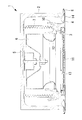
- the collection box is installed on the suction grille, and the comb is installed above the collection box. Therefore, by lowering the suction grill, the comb is moved downward together with the collection box arranged on the suction grille. You can take it down. As a result, since the comb portion can be cleaned not at the ceiling but at the position where the comb portion is lowered, it is not necessary to work at a high place for cleaning the comb portion.
- the comb section may be configured to be detachable from the collection box section. According to this configuration, the comb portion can be removed from the collection box portion, and the comb portion can be cleaned separately from the collection box portion.
- An air conditioner according to one embodiment of the present invention includes the above-described filter cleaning unit.
- the comb portion for scraping off the dust attached to the brush can be cleaned at the position where the comb portion is lowered, so that the work for high places is not required for cleaning the comb portion.
- the ceiling-embedded air conditioner (hereinafter, referred to as “air conditioner”) includes an indoor unit 1, an outdoor unit (not shown), and a refrigerant pipe (not shown) connecting the indoor unit 1 and the outdoor unit. And so on.
- the indoor unit 1 is installed with the case body 2 embedded in the ceiling.
- a heat exchanger 7, a drain pan 10, a motor 5, a blower 6, a bell mouth 12, and the like are built in the case body 2, and a lower part of the case body 2 is exposed to a ceiling surface.
- the panel section 8 is mounted.
- a suction port 3 is formed at the center of the lower surface of the indoor unit 1, and is long in one direction along the outer peripheral portion of the lower surface of the indoor unit 1 at a position adjacent to the suction port 3.
- An outlet 4 is formed.
- a suction grille 11 and a filter 13 are installed above the suction grille 11 at the suction opening 3.
- the drain pan 10 is provided below the heat exchanger 7 and receives drain water dropped from the heat exchanger 7.
- the bellmouth 12 is provided below the drain pan 10.
- the louver 14 is long in one direction according to the shape of the outlet 4, and the louver 14 rotates around an axis parallel to the longitudinal direction. As a result, when the direction of the louver 14 is changed, the airflow blown out from the blowout port 4 becomes upward or downward.
- the filter 13 removes dust and the like contained in the inhaled air.
- the filter 13 has a square shape like the suction port 3, and is arranged near the center of the suction port 3. Further, wires 15 for raising and lowering the suction grill 11 are arranged at four corners of the frame of the suction grill 11.
- the indoor unit 1 includes the filter cleaning unit 16.
- the filter cleaning unit 16 is provided on the panel section 8 on the lower surface of the filter 13, and has a brush 17 which is equal to or longer than one side of the filter 13 in one direction. By moving the brush 17 of the filter cleaning unit 16 from one side of the filter 13 to the other side while contacting the surface of the filter 13, dust attached to the filter 13 is removed.
- the filter cleaning unit 16 starts operation based on a control signal related to operation control.
- the filter cleaning unit 16 includes a frame unit 9 detachably installed on the panel unit 8, a brush 17 installed on the frame unit 9, a brush fixing unit 21, a motor 24, and the like. Prepare.
- the frame portion 9 has a square shape like the suction port 3, and is disposed near the center of the suction port 3.
- a filter 13 is provided on the frame unit 9, and the frame unit 9 can be attached to or detached from the panel unit 8.
- the brush 17 has a shaft member that is long in one direction, and a large number of hairs are arranged from one end to the other end in the axial direction on the outer peripheral surface of the shaft member.
- the brush 17 is provided with a brush rotation gear (not shown) that meshes with the pinion gear at each end.
- the brush 17 is supported at both ends by the brush fixing portions 21.
- the brush fixing portion 21 is a member that is long in a direction parallel to the axial direction of the brush 17, and accommodates the brush 17 inside.
- the brush fixing portion 21 has a shape surrounding the brush 17 and exposes the brush 17 on the filter 13 side.
- a total of two pinion gears (not shown) are rotatably installed at both ends in the longitudinal direction of the brush fixing portion 21.
- the brush fixing part 21 is supported by a rack gear 22 via a pinion gear. As the brush fixing portion 21 moves along the rack gear 22, the brush fixing portion 21 and the brush 17 move along the surface of the filter 13 from one side of the filter 13 to the other side.
- Pinion gears are respectively installed at both ends of the brush fixing portion 21.
- the pinion gear meshes with the rack gear 22.
- the rack gear 22 is installed outside the filter 13 such that the axial direction is perpendicular to the axial direction of the brush 17.
- the length of the rack gear 22 is equal to or longer than the length of one side of the filter 13.
- Brush rotation gears are provided one for each pinion gear, and mesh with the pinion gears.
- the brush rotation gear is driven to rotate by the force transmitted from the pinion gear.
- the brush 17 installed on the brush rotation gear rotates, and the brush 17 rotates with the movement of the brush 17.
- the pinion gear is a member that is not connected to the motor 24 and operates in a driven manner.
- the pinion gear is provided on the brush fixing portion 21, unlike the Patent Document 1, a propulsion shaft connecting the two pinion gears is unnecessary.
- the motor 24 is fixedly installed on the frame 9 of the filter cleaning unit 16.
- the motor 24 is connected to a shaft 25, and the motor 25 drives the shaft 25 to rotate around the axis.
- the shaft 25 is a shaft member that is long in one direction, a male screw is formed on the outer peripheral surface of the shaft member, and a nut 26 is engaged with the shaft member.
- the shaft 25 is installed so that the axial direction is perpendicular to the axial direction of the brush 17, that is, in a direction parallel to the rack gear 22.
- the shaft 25 is equal to or longer than the length of one side of the filter 13 in one direction.
- the nut 26 has an internal thread formed on the inner peripheral surface thereof that meshes with the external thread of the shaft 25.
- the nut 26 is connected to the brush fixing part 21 so as not to rotate around the axis of the shaft 25.
- the nut 26 is not fixed to the brush fixing part 21, but the nut 26 is connected to the brush fixing part 21 so that the brush fixing part 21 can be pushed.
- the rotation of the shaft 25 causes the nut 26 to move, and the nut 26 pushes the brush fixing portion 21 to move along the axial direction of the shaft 25.
- the traveling direction of the nut 26 and the brush fixing portion 21 can be changed.
- the male screw is formed on the shaft 25 and the female screw is formed on the nut 26, and the present invention is not limited to this example.
- the shaft 25 and the nut 26 may be configured such that a combination of the shaft 25 and the nut 26 provides a ball screw mechanism.
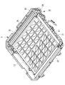
- the collection box section 38 is disposed on the surface of the suction grill 11 on the filter 13 side, and is connectable to the brush fixing section 21 located above the collection box section 38.
- the collection box 38 is a member that is long in a direction parallel to the axial direction of the brush 17. As shown in FIGS. 4 to 6, the collection box section 38 includes a collection box 39, a support section 40, a comb section 41, and the like.
- the collection box 39 is a box in which the dust removed by the brush 17 is stored, has a length equal to or longer than the axial length of the brush 17, and has a width longer than the diameter of the brush 17. .
- the collection box 39 is installed between the support part 40 and the suction grill 11.
- the support part 40 is installed on the upper part of the collection box 39.
- the support portion 40 has a rectangular shape that is long in a direction parallel to the axial direction of the brush 17, and has a frame installed along the edge of the opening of the collection box 39. Both ends in the longitudinal direction of the support portion 40 are slidably connected to rails 43 provided on the suction grill 11. Thereby, the collection box 39 is supported by the suction grill 11 via the support portion 40.
- the collection box 39 can move in and out between the support portion 40 and the suction grill 11 in a direction parallel to the in-plane direction of the suction grill 11.
- the comb part 41 is installed on the upper part of the support part 40 and is detachable from the support part 40.
- the comb portion 41 has a rectangular shape that is long in a direction parallel to the axial direction of the brush 17, and has a frame installed along the edge of the support portion 40. Note that locking portions 54 and 55 may be provided on the support portion 40 and the comb portion 41 so that the comb portion 41 does not move with respect to the support portion 40.
- a long comb 44 is formed in the widthwise center of the comb portion 41 in a direction parallel to the axial direction of the brush 17.
- the comb 44 has a comb tip protruding toward the brush 17, that is, upward.
- the comb 44 contacts the brush 17 in a state where the brush fixing part 21 and the collection box part 38 are connected.
- the comb 44 comes into contact with the brush 17 and scrapes off dust attached to the brush 17. The scraped dust is collected in the collection box 39.
- the comb portion 41 is provided on the suction grill 11 side. Therefore, as shown in FIG. 2, the comb portion 41 can be cleaned together with the collection box 39 by lowering the suction grill 11. Therefore, unlike the case where the comb is installed on the case body 2 side of the indoor unit, when cleaning the comb 44, work at a high place is not required.
Landscapes
- Engineering & Computer Science (AREA)
- Chemical & Material Sciences (AREA)
- Combustion & Propulsion (AREA)
- Mechanical Engineering (AREA)
- General Engineering & Computer Science (AREA)
- Chemical Kinetics & Catalysis (AREA)
- Air Filters, Heat-Exchange Apparatuses, And Housings Of Air-Conditioning Units (AREA)
- Filtering Of Dispersed Particles In Gases (AREA)
Abstract
La présente invention a pour but de permettre un nettoyage au niveau d'une position d'abaissement d'une partie peigne servant à racler la poussière collée à une brosse, et d'éviter le besoin d'effectuer un travail de nettoyage de la partie peigne au niveau d'un emplacement élevé. À cet effet, une unité de nettoyage de filtre comprend : une partie de fixation de brosse pouvant recevoir une brosse disposée le long d'une direction d'un filtre ; un mécanisme d'entraînement pouvant déplacer la partie de fixation de brosse dans une direction perpendiculaire à ladite direction et le long de la surface externe du filtre ; une partie boîte de collecte (38) installée sur une grille d'aspiration agencée en dessous de la brosse, se déplaçant avec la partie de fixation de brosse grâce au mécanisme d'entraînement, et dans laquelle la poussière retirée de la brosse est collectée ; et la partie peigne (41) disposé au-dessus de la partie boîte de collecte (38) et comportant un peigne (44) faisant saillie vers la brosse.
Applications Claiming Priority (2)
| Application Number | Priority Date | Filing Date | Title |
|---|---|---|---|
| JP2018-122246 | 2018-06-27 | ||
| JP2018122246A JP7566450B2 (ja) | 2018-06-27 | 2018-06-27 | フィルタ清掃ユニット及び空気調和機 |
Publications (1)
| Publication Number | Publication Date |
|---|---|
| WO2020004042A1 true WO2020004042A1 (fr) | 2020-01-02 |
Family
ID=68986443
Family Applications (1)
| Application Number | Title | Priority Date | Filing Date |
|---|---|---|---|
| PCT/JP2019/023329 Ceased WO2020004042A1 (fr) | 2018-06-27 | 2019-06-12 | Unité de nettoyage de filtre et climatiseur |
Country Status (2)
| Country | Link |
|---|---|
| JP (1) | JP7566450B2 (fr) |
| WO (1) | WO2020004042A1 (fr) |
Cited By (1)
| Publication number | Priority date | Publication date | Assignee | Title |
|---|---|---|---|---|
| CN113091183A (zh) * | 2021-04-13 | 2021-07-09 | 珠海市世纪建设工程有限公司 | 一种绿色建筑的室内通风智能化循环系统 |
Families Citing this family (2)
| Publication number | Priority date | Publication date | Assignee | Title |
|---|---|---|---|---|
| JP7739036B2 (ja) * | 2021-04-30 | 2025-09-16 | 三菱重工サーマルシステムズ株式会社 | フィルタ清掃ユニット及び空気調和機 |
| CN115046247B (zh) * | 2022-05-16 | 2023-03-24 | 艾德兄弟(北京)机电工程有限公司 | 一种空调 |
Citations (2)
| Publication number | Priority date | Publication date | Assignee | Title |
|---|---|---|---|---|
| JP2009264659A (ja) * | 2008-04-24 | 2009-11-12 | Mitsubishi Heavy Ind Ltd | 室内機ユニットおよび空気調和機 |
| JP2010078267A (ja) * | 2008-09-29 | 2010-04-08 | Sanyo Electric Co Ltd | 空気調和機 |
Family Cites Families (3)
| Publication number | Priority date | Publication date | Assignee | Title |
|---|---|---|---|---|
| JP2012112586A (ja) * | 2010-11-25 | 2012-06-14 | Toshiba Carrier Corp | 空気調和機の室内ユニット |
| JP5563047B2 (ja) * | 2012-11-12 | 2014-07-30 | 三菱重工業株式会社 | 室内機ユニットおよび空気調和機 |
| JP6423626B2 (ja) * | 2014-06-24 | 2018-11-14 | 日立ジョンソンコントロールズ空調株式会社 | 空気調和機 |
-
2018
- 2018-06-27 JP JP2018122246A patent/JP7566450B2/ja active Active
-
2019
- 2019-06-12 WO PCT/JP2019/023329 patent/WO2020004042A1/fr not_active Ceased
Patent Citations (2)
| Publication number | Priority date | Publication date | Assignee | Title |
|---|---|---|---|---|
| JP2009264659A (ja) * | 2008-04-24 | 2009-11-12 | Mitsubishi Heavy Ind Ltd | 室内機ユニットおよび空気調和機 |
| JP2010078267A (ja) * | 2008-09-29 | 2010-04-08 | Sanyo Electric Co Ltd | 空気調和機 |
Cited By (2)
| Publication number | Priority date | Publication date | Assignee | Title |
|---|---|---|---|---|
| CN113091183A (zh) * | 2021-04-13 | 2021-07-09 | 珠海市世纪建设工程有限公司 | 一种绿色建筑的室内通风智能化循环系统 |
| CN113091183B (zh) * | 2021-04-13 | 2022-04-26 | 珠海市世纪建设工程有限公司 | 一种绿色建筑的室内通风智能化循环系统 |
Also Published As
| Publication number | Publication date |
|---|---|
| JP2020000987A (ja) | 2020-01-09 |
| JP7566450B2 (ja) | 2024-10-15 |
Similar Documents
| Publication | Publication Date | Title |
|---|---|---|
| KR101167890B1 (ko) | 덕트용 청소 기구 | |
| JP4611448B2 (ja) | 室内機ユニットおよび空気調和機 | |
| CN111043656B (zh) | 空调室内机及具有其的空调系统 | |
| CN102203516B (zh) | 过滤器和具备该过滤器的空气调节装置 | |
| JP6423626B2 (ja) | 空気調和機 | |
| WO2020004042A1 (fr) | Unité de nettoyage de filtre et climatiseur | |
| JP7134739B2 (ja) | フィルタ清掃ユニット及び空気調和機 | |
| JP7134738B2 (ja) | フィルタ清掃ユニット及び空気調和機 | |
| JP2005083612A (ja) | 空気調和機 | |
| JP2020003169A (ja) | フィルタ清掃ユニット及び空気調和機 | |
| JP7490330B2 (ja) | フィルタ清掃ユニット及び空気調和機 | |
| CN101310150B (zh) | 空调机 | |
| CN101313179A (zh) | 空调机的室内机 | |
| JP7330671B2 (ja) | フィルタ清掃ユニット及び空気調和機 | |
| JP4533366B2 (ja) | フィルタ及びフィルタ清掃装置及び空気調和機 | |
| JP5092409B2 (ja) | 空気調和機 | |
| CN211400009U (zh) | 空调室内机及具有其的空调系统 | |
| JP7330674B2 (ja) | フィルタ清掃ユニット及び空気調和機 | |
| WO2019244545A1 (fr) | Unité de nettoyage de filtre et climatiseur | |
| JP2011012936A (ja) | 天井埋込型空気調和機 | |
| WO2019244525A1 (fr) | Unité de nettoyage de filtre et climatiseur | |
| JP7739036B2 (ja) | フィルタ清掃ユニット及び空気調和機 | |
| JP5517693B2 (ja) | フィルターの自動清掃装置、空気調和機及び空気清浄機 | |
| CN216522059U (zh) | 滤网装置、室内机和空调器 | |
| JP2008111579A (ja) | フィルタ清掃装置および空気調和機 |
Legal Events
| Date | Code | Title | Description |
|---|---|---|---|
| 121 | Ep: the epo has been informed by wipo that ep was designated in this application |
Ref document number: 19827440 Country of ref document: EP Kind code of ref document: A1 |
|
| NENP | Non-entry into the national phase |
Ref country code: DE |
|
| 122 | Ep: pct application non-entry in european phase |
Ref document number: 19827440 Country of ref document: EP Kind code of ref document: A1 |