WO2020004057A1 - Frein à disque - Google Patents
Frein à disque Download PDFInfo
- Publication number
- WO2020004057A1 WO2020004057A1 PCT/JP2019/023446 JP2019023446W WO2020004057A1 WO 2020004057 A1 WO2020004057 A1 WO 2020004057A1 JP 2019023446 W JP2019023446 W JP 2019023446W WO 2020004057 A1 WO2020004057 A1 WO 2020004057A1
- Authority
- WO
- WIPO (PCT)
- Prior art keywords
- disc brake
- caliper
- electric motor
- carrier
- pin
- Prior art date
- Legal status (The legal status is an assumption and is not a legal conclusion. Google has not performed a legal analysis and makes no representation as to the accuracy of the status listed.)
- Ceased
Links
Images



Classifications
-
- F—MECHANICAL ENGINEERING; LIGHTING; HEATING; WEAPONS; BLASTING
- F16—ENGINEERING ELEMENTS AND UNITS; GENERAL MEASURES FOR PRODUCING AND MAINTAINING EFFECTIVE FUNCTIONING OF MACHINES OR INSTALLATIONS; THERMAL INSULATION IN GENERAL
- F16D—COUPLINGS FOR TRANSMITTING ROTATION; CLUTCHES; BRAKES
- F16D55/00—Brakes with substantially-radial braking surfaces pressed together in axial direction, e.g. disc brakes
- F16D55/02—Brakes with substantially-radial braking surfaces pressed together in axial direction, e.g. disc brakes with axially-movable discs or pads pressed against axially-located rotating members
- F16D55/22—Brakes with substantially-radial braking surfaces pressed together in axial direction, e.g. disc brakes with axially-movable discs or pads pressed against axially-located rotating members by clamping an axially-located rotating disc between movable braking members, e.g. movable brake discs or brake pads
- F16D55/224—Brakes with substantially-radial braking surfaces pressed together in axial direction, e.g. disc brakes with axially-movable discs or pads pressed against axially-located rotating members by clamping an axially-located rotating disc between movable braking members, e.g. movable brake discs or brake pads with a common actuating member for the braking members
- F16D55/225—Brakes with substantially-radial braking surfaces pressed together in axial direction, e.g. disc brakes with axially-movable discs or pads pressed against axially-located rotating members by clamping an axially-located rotating disc between movable braking members, e.g. movable brake discs or brake pads with a common actuating member for the braking members the braking members being brake pads
- F16D55/226—Brakes with substantially-radial braking surfaces pressed together in axial direction, e.g. disc brakes with axially-movable discs or pads pressed against axially-located rotating members by clamping an axially-located rotating disc between movable braking members, e.g. movable brake discs or brake pads with a common actuating member for the braking members the braking members being brake pads in which the common actuating member is moved axially, e.g. floating caliper disc brakes
- F16D55/2265—Brakes with substantially-radial braking surfaces pressed together in axial direction, e.g. disc brakes with axially-movable discs or pads pressed against axially-located rotating members by clamping an axially-located rotating disc between movable braking members, e.g. movable brake discs or brake pads with a common actuating member for the braking members the braking members being brake pads in which the common actuating member is moved axially, e.g. floating caliper disc brakes the axial movement being guided by one or more pins engaging bores in the brake support or the brake housing
- F16D55/22655—Constructional details of guide pins
-
- F—MECHANICAL ENGINEERING; LIGHTING; HEATING; WEAPONS; BLASTING
- F16—ENGINEERING ELEMENTS AND UNITS; GENERAL MEASURES FOR PRODUCING AND MAINTAINING EFFECTIVE FUNCTIONING OF MACHINES OR INSTALLATIONS; THERMAL INSULATION IN GENERAL
- F16D—COUPLINGS FOR TRANSMITTING ROTATION; CLUTCHES; BRAKES
- F16D55/00—Brakes with substantially-radial braking surfaces pressed together in axial direction, e.g. disc brakes
- F16D55/02—Brakes with substantially-radial braking surfaces pressed together in axial direction, e.g. disc brakes with axially-movable discs or pads pressed against axially-located rotating members
- F16D55/22—Brakes with substantially-radial braking surfaces pressed together in axial direction, e.g. disc brakes with axially-movable discs or pads pressed against axially-located rotating members by clamping an axially-located rotating disc between movable braking members, e.g. movable brake discs or brake pads
- F16D55/224—Brakes with substantially-radial braking surfaces pressed together in axial direction, e.g. disc brakes with axially-movable discs or pads pressed against axially-located rotating members by clamping an axially-located rotating disc between movable braking members, e.g. movable brake discs or brake pads with a common actuating member for the braking members
- F16D55/225—Brakes with substantially-radial braking surfaces pressed together in axial direction, e.g. disc brakes with axially-movable discs or pads pressed against axially-located rotating members by clamping an axially-located rotating disc between movable braking members, e.g. movable brake discs or brake pads with a common actuating member for the braking members the braking members being brake pads
- F16D55/226—Brakes with substantially-radial braking surfaces pressed together in axial direction, e.g. disc brakes with axially-movable discs or pads pressed against axially-located rotating members by clamping an axially-located rotating disc between movable braking members, e.g. movable brake discs or brake pads with a common actuating member for the braking members the braking members being brake pads in which the common actuating member is moved axially, e.g. floating caliper disc brakes
- F16D55/2265—Brakes with substantially-radial braking surfaces pressed together in axial direction, e.g. disc brakes with axially-movable discs or pads pressed against axially-located rotating members by clamping an axially-located rotating disc between movable braking members, e.g. movable brake discs or brake pads with a common actuating member for the braking members the braking members being brake pads in which the common actuating member is moved axially, e.g. floating caliper disc brakes the axial movement being guided by one or more pins engaging bores in the brake support or the brake housing
- F16D55/227—Brakes with substantially-radial braking surfaces pressed together in axial direction, e.g. disc brakes with axially-movable discs or pads pressed against axially-located rotating members by clamping an axially-located rotating disc between movable braking members, e.g. movable brake discs or brake pads with a common actuating member for the braking members the braking members being brake pads in which the common actuating member is moved axially, e.g. floating caliper disc brakes the axial movement being guided by one or more pins engaging bores in the brake support or the brake housing by two or more pins
-
- B—PERFORMING OPERATIONS; TRANSPORTING
- B60—VEHICLES IN GENERAL
- B60T—VEHICLE BRAKE CONTROL SYSTEMS OR PARTS THEREOF; BRAKE CONTROL SYSTEMS OR PARTS THEREOF, IN GENERAL; ARRANGEMENT OF BRAKING ELEMENTS ON VEHICLES IN GENERAL; PORTABLE DEVICES FOR PREVENTING UNWANTED MOVEMENT OF VEHICLES; VEHICLE MODIFICATIONS TO FACILITATE COOLING OF BRAKES
- B60T13/00—Transmitting braking action from initiating means to ultimate brake actuator with power assistance or drive; Brake systems incorporating such transmitting means, e.g. air-pressure brake systems
- B60T13/74—Transmitting braking action from initiating means to ultimate brake actuator with power assistance or drive; Brake systems incorporating such transmitting means, e.g. air-pressure brake systems with electrical assistance or drive
-
- F—MECHANICAL ENGINEERING; LIGHTING; HEATING; WEAPONS; BLASTING
- F16—ENGINEERING ELEMENTS AND UNITS; GENERAL MEASURES FOR PRODUCING AND MAINTAINING EFFECTIVE FUNCTIONING OF MACHINES OR INSTALLATIONS; THERMAL INSULATION IN GENERAL
- F16D—COUPLINGS FOR TRANSMITTING ROTATION; CLUTCHES; BRAKES
- F16D65/00—Parts or details
- F16D65/14—Actuating mechanisms for brakes; Means for initiating operation at a predetermined position
- F16D65/16—Actuating mechanisms for brakes; Means for initiating operation at a predetermined position arranged in or on the brake
- F16D65/18—Actuating mechanisms for brakes; Means for initiating operation at a predetermined position arranged in or on the brake adapted for drawing members together, e.g. for disc brakes
-
- F—MECHANICAL ENGINEERING; LIGHTING; HEATING; WEAPONS; BLASTING
- F16—ENGINEERING ELEMENTS AND UNITS; GENERAL MEASURES FOR PRODUCING AND MAINTAINING EFFECTIVE FUNCTIONING OF MACHINES OR INSTALLATIONS; THERMAL INSULATION IN GENERAL
- F16D—COUPLINGS FOR TRANSMITTING ROTATION; CLUTCHES; BRAKES
- F16D2121/00—Type of actuator operation force
- F16D2121/18—Electric or magnetic
- F16D2121/24—Electric or magnetic using motors
-
- F—MECHANICAL ENGINEERING; LIGHTING; HEATING; WEAPONS; BLASTING
- F16—ENGINEERING ELEMENTS AND UNITS; GENERAL MEASURES FOR PRODUCING AND MAINTAINING EFFECTIVE FUNCTIONING OF MACHINES OR INSTALLATIONS; THERMAL INSULATION IN GENERAL
- F16D—COUPLINGS FOR TRANSMITTING ROTATION; CLUTCHES; BRAKES
- F16D2125/00—Components of actuators
- F16D2125/18—Mechanical mechanisms
- F16D2125/20—Mechanical mechanisms converting rotation to linear movement or vice versa
- F16D2125/34—Mechanical mechanisms converting rotation to linear movement or vice versa acting in the direction of the axis of rotation
- F16D2125/40—Screw-and-nut
-
- F—MECHANICAL ENGINEERING; LIGHTING; HEATING; WEAPONS; BLASTING
- F16—ENGINEERING ELEMENTS AND UNITS; GENERAL MEASURES FOR PRODUCING AND MAINTAINING EFFECTIVE FUNCTIONING OF MACHINES OR INSTALLATIONS; THERMAL INSULATION IN GENERAL
- F16D—COUPLINGS FOR TRANSMITTING ROTATION; CLUTCHES; BRAKES
- F16D2125/00—Components of actuators
- F16D2125/18—Mechanical mechanisms
- F16D2125/44—Mechanical mechanisms transmitting rotation
- F16D2125/46—Rotating members in mutual engagement
- F16D2125/50—Rotating members in mutual engagement with parallel non-stationary axes, e.g. planetary gearing
Definitions
- the present invention relates to a disc brake provided with an electric motor, which is used for braking a vehicle.
- Patent Document 1 discloses a caliper having a piston that presses brake pads disposed on both sides of a disc rotor against the disc rotor, a driving mechanism provided on the caliper to drive the piston,
- a disc brake including a transmission mechanism for transmitting a driving force of an electric motor to the driving mechanism, and a housing that houses the transmission mechanism and is attached to the caliper is disclosed.
- the object of the present invention is to provide a disk brake that suppresses an increase in size and improves mountability on a vehicle.
- the disc brake according to one embodiment of the present invention includes a carrier fixed to a non-rotating portion of a vehicle, a caliper attached to the carrier and having a piston pressing a braking member, and any one of the carrier and the caliper.
- a fixed pin which has a slide pin for supporting the caliper slidably in the axial direction of the wheel with respect to the carrier, a motor and a speed reduction mechanism, and transmits a driving force of the motor to the piston via the speed reduction mechanism.
- at least a part of the drive mechanism is disposed on an extension of the axis of the slide pin.
- the disk brake according to one embodiment of the present invention it is possible to suppress an increase in size and improve the mountability on a vehicle.
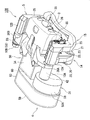
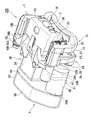
- FIG. 2 is a perspective view of the disc brake according to the first embodiment.
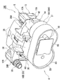
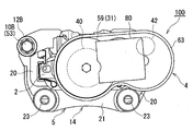
- FIG. 2 is a perspective view of the disc brake according to the first embodiment. The front view from the inner side in the disc brake concerning 1st Embodiment.
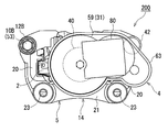
- FIG. 3 is a rear view from the outer side of the disc brake according to the first embodiment, in which the inner and outer brake pads are not shown.
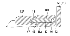
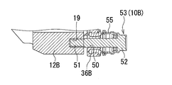
- FIG. 2 is a cross-sectional view illustrating a support structure using one slide pin employed in the disc brake of FIG. 1.
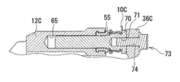
- FIG. 2 is a sectional view showing a support structure by the other slide pin employed in the disc brake of FIG. 1. Sectional drawing which shows the support structure by the slide pin which concerns on other embodiment.
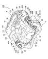
- FIG. 9 is a perspective view of a disc brake according to a second embodiment.
- FIG. 9 is a perspective view of a disc brake according to a second embodiment.
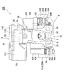
- FIG. 9 is a perspective view of a disc brake according to a second embodiment. The front view from the inner side in the disc brake concerning a 2nd embodiment.
- FIG. 13 is a perspective view of a disc brake according to a third embodiment.
- FIG. 10 is a plan view of a disc brake according to a third embodiment.
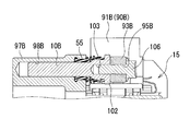
- FIG. 12 is an exemplary sectional view showing a support structure using one slide pin employed in the disc brake of FIG. 11;
- FIG. 12 is a cross-sectional view illustrating a support structure using the other slide pin employed in the disc brake of FIG. 11.
- the disc brakes 100, 200, and 300 according to the first to third embodiments are electric brake devices that generate a braking force by driving the electric motor 58 during normal running.
- the inside of the vehicle is referred to as an inner side
- the outside of the vehicle is referred to as an outer side.
- a disc brake 100 according to a first embodiment will be described with reference to FIGS.
- the disc brake 100 according to the first embodiment includes a pair of braking members, which are disposed on both sides in the axial direction with a disc rotor D attached to a rotating portion of the vehicle therebetween.
- An inner brake pad 2 (see FIG.
- the disc brake 100 is configured as a caliper floating type.
- the pair of inner and outer brake pads 2 and 3 and the caliper 4 are mounted on a carrier 5 fixed to a non-rotating portion such as a knuckle of the vehicle in the axial direction of the disk rotor D (wheel) with respect to the carrier 5. It is movably supported.
- the carrier 5 is integrally connected to a pair of pin supports 12A and 12B on which the slide pins 10A and 10B are respectively supported, and to a pair of pin supports 12A and 12B. And inner-side and outer-side support portions 14, 15 for independently supporting the outer brake pads 2, 3, respectively.
- the pair of pin support portions 12A and 12B are arranged at intervals along the rotation direction of the disk rotor D, and both extend along the axial direction of the disk rotor D (vehicle).
- Each of the pin support portions 12A and 12B is formed in a substantially columnar shape.
- a press-fit recess 18 is formed on the inner end surface of one of the pin support portions 12A. As shown in FIG.
- a female screw hole 19 is formed in the inner end surface of the other pin support portion 12B.
- an inner-side support portion 14 is integrally connected to the inner side of each of the pin support portions 12A and 12B.
- Outer support portions 15 of the respective pin support portions 12A and 12B are integrally connected to the inner support portion 14 at intervals from the inner support portion 14 to the outer side along the axial direction of the disk rotor D.
- the inner-side support portion 14 connects a pair of inner-side arm portions 20, 20 extending in directions substantially orthogonal to the respective pin support portions 12 ⁇ / b> A, 12 ⁇ / b> B with inner ends of the pair of inner-side arm portions 20, 20. And a side beam portion 21.
- the inner brake pad 2 is supported movably along the axial direction of the disk rotor D inside the pair of inner side arms 20, 20. At both ends of the inner beam portion 21 in the rotation direction of the disk rotor D, through holes 23, 23 penetrating along the axial direction of the disk rotor D are formed, respectively.
- the carrier 5 is attached to a non-rotating portion of the vehicle via respective through holes 23 provided in the inner support portion 14 (the inner beam portion 21).
- the outer-side support portion 15 is a pair of outer-side arms 25, 25 extending in a direction substantially orthogonal to the pin support portions 12A, 12B, and an outer-side connecting the ends of the pair of outer-side arms 25, 25. And a beam section 26.
- the outer brake pad 3 is movably supported inside the pair of outer side arm portions 25, 25 along the axial direction of the disk rotor D.
- the caliper 4 includes a caliper body 30 that is a main body of the caliper 4, an electric motor 58, and a reduction mechanism 59, and the driving force from the electric motor 58 is transmitted through the reduction mechanism 59. And a drive mechanism 31 that transmits the force to a piston 40 (see also FIG. 4) in a cylinder portion 34 (cylinder bore) of the caliper body 30.
- the caliper main body 30 is disposed on the base end side facing the inner brake pad 2 inside the vehicle, and has a cylindrical cylinder portion 34 opened to face the inner brake pad 2.
- a pair of claw portions 35, 35 extending on the outer side by straddling and disposed on the distal end side facing the outer brake pad 3 on the outer side, and a pair of caliper arms 36A, 36B extending radially outward from the cylinder portion 34. are integrally formed.
- a piston 40 (see FIGS. 3 and 4) is supported in the cylinder bore of the cylinder portion 34 so as to be movable along the axial direction so as not to rotate relatively.
- a driving force from an electric motor 58 which is a configuration of the drive mechanism 31, which will be described later, is transmitted to the piston 40 via a speed reduction mechanism 59, which is a configuration of the drive mechanism 31, and a thrust applying mechanism 60.
- the inner brake pad 2 is pressed while moving toward the disk rotor D.
- the driving force from the electric motor 58 constituting the drive mechanism 31 is transmitted to the piston 40 via the speed reduction mechanism 59 and the thrust applying mechanism 60 constituting the drive mechanism 31, and the piston 40 is moved.
- the inner brake pad 2 retreats.
- a cylindrical boss portion 42 having a bottom is integrally protruded toward the inner side at the tip of one of the caliper arm portions 36A and 36B. .
- the boss portion 42 extends along the axial direction of the disk rotor D.
- a sliding hole 43 opened at an outer end surface is formed at a predetermined depth.
- a sliding shaft portion 46 extending from the flange portion 45 toward the inner side and a fixed shaft portion 47 extending from the flange portion 45 toward the outer side are integrally formed.
- the fixed shaft portion 47 of the one slide pin 10A is press-fitted and fixed to the press-fitting concave portion 18 provided on the inner side end surface of the one pin support portion 12A, and the slide shaft portion 46 becomes the one caliper arm portion 36A. It is slidably inserted along the axial direction into a sliding hole 43 provided in the (boss 42). As a result, the caliper main body 30 can be slidably supported on the carrier 5 along the axial direction of the disk rotor D (wheel) by the one slide pin 10A. Note that the fixing shaft portion 47 of one slide pin 10A and the one pin support portion 12A may be screwed together.
- a through hole 50 is formed at the tip of the other caliper arm portion 36B of the pair of caliper arm portions 36A, 36B so as to penetrate in the axial direction of disk rotor D.
- the other slide pin 10 ⁇ / b> B is composed of a hexagon bolt 53 having a hexagonal head 52.
- the male screw portion 51 of the hexagon bolt 53 serving as the slide pin 10B is screwed into the female screw hole 19 provided on the inner side end surface of the other pin support portion 12B while being inserted into the through hole 50 of the other caliper arm portion 36B. Is done.
- the caliper body 30 can be slidably supported on the carrier 5 along the axial direction of the disk rotor D (wheel) by the other slide pin 10B.
- An axial gap is provided between the inner end face of the other caliper arm 36B and the hexagonal head 52 of the other slide pin 10B (hexagonal bolt 53).
- the hexagonal bolt 53 as the slide pin 10B has its hexagonal head 52 located on the inner side of the electric motor 58 and the reduction mechanism 59 in the axial direction of the disk rotor D.
- the drive mechanism 31 includes an electric motor 58 that is an electric motor, a reduction mechanism 59 that increases the rotational torque from the electric motor 58, and a rotational movement from the reduction mechanism 59 that is linear. And a thrust applying mechanism 60 that converts and applies a thrust to the piston 40.
- the electric motor 58 is arranged such that its axis is substantially parallel to the axis of the cylinder portion 34 of the caliper body 30.
- the electric motor 58 is configured such that the outer diameter of the main body 58A is larger than its axial length.
- the rotating shaft (not shown) of the electric motor 58 extends along the axial direction of the disk rotor D, and extends into a gear housing 63 described later.
- a part of the drive mechanism 31, that is, the electric motor 58 is arranged on an extension of the axis of one of the slide pins 10A.
- the electric motor 58 is arranged on an extension of the axis of the boss 42 provided on one of the caliper arms 36A.
- the electric motor 58 axially overlaps the boss 42 provided on the one caliper arm 36A, that is, the one slide pin 10A.
- the bottom surface of the boss portion 42 is close to the bottom surface of the electric motor 58 while the bottom surface of the body portion 58A of the electric motor 58 and the bottom surface (the inner surface) of the boss portion 42 provided on one of the caliper arms 36A face each other. Placed. Within the radial range of the bottom surface of the electric motor 58, the entire radial region of the boss portion 42 provided on the one caliper arm portion 36A, and naturally the entire radial region of the one slide pin 10A is located.
- the speed reduction mechanism 59 increases the rotational torque from the electric motor 58 and transmits the torque to the thrust applying mechanism 60.
- a planetary gear reduction mechanism or the like is employed as the reduction mechanism 59.
- the speed reduction mechanism 59 is housed in the gear housing 63.
- the rotation of the electric motor 58 from the rotation shaft is transmitted to the reduction mechanism 59.
- the gear housing 63 is disposed so as to straddle the cylinder portion 34 of the caliper body 30 and the electric motor 58.
- the gear housing 63 is formed to have a size that covers the entire area of the cylinder portion 34 and the electric motor 58 from the inner side.
- the gear housing 63 may be formed to have a size that covers a portion of the cylinder portion 34 and the entire area of the electric motor 58 from the inner side, and a size that covers the entire area of the cylinder portion 34 and a portion of the electric motor 58. It may be formed in a size that covers a part of the cylinder part 34 and a part of the electric motor 58. In short, the size of the gear housing 63 is not particularly limited.
- One pin support portion 12A including one slide pin 10A is disposed so as to be covered from the inner side by a gear housing 63, and the other pin support portion 12B including the other slide pin 10B is disposed outside the gear housing 63.
- the pair of pin supporting portions 12A and 12B including the pair of slide pins 10A and 10B may be arranged so as to be covered from the inner side by the gear housing 63.
- the thrust applying mechanism 60 is disposed in the cylinder bore of the cylinder portion 34 of the caliper body 30 and between the bottom of the cylinder portion 34 and the piston 40.
- the thrust applying mechanism 60 converts the rotational motion from the speed reduction mechanism 59 into a linear motion and applies thrust to the piston 40.
- a rotation / linear motion converting mechanism such as a ball screw mechanism or a ball and ramp mechanism is used. Adopted.
- a support structure using a pair of slide pins 10A and 10B that is, a support structure in which the caliper body 30 is slidably supported in the axial direction by the pair of slide pins 10A and 10B
- the support structure using the pin 10A may be adopted for both the support structure using the pair of slide pins 10A and 10B, or the support structure using the other slide pin 10B shown in FIG. It may be adopted for both of the support structures.
- a support structure using a slide pin 10C according to another embodiment shown in FIG. 7 may be used for both or one of the support structures using a pair of slide pins 10A and 10B.
- a slide hole 65 having a predetermined depth from the inner side end face is formed in a pin support portion 12C of the carrier 5. Is formed.
- the slide pin 10C has a hexagonal head 70 at the inner end and a female screw hole 71 having a predetermined depth from the radial center of the inner end surface. Then, the slide pin 10C is inserted into the slide hole 65 of the pin support portion 12C, and the inner side end surface of the hexagonal head 70 of the slide pin 10C contacts the corresponding caliper arm portion 36C of the caliper body 30.
- the hexagon bolt 73 is inserted into the through hole 74 of the caliper arm portion 36C, and screwed into the female screw hole 71 of the slide pin 10C.
- the slide pin 10C is fixed to the caliper arm portion 36C of the caliper main body 30 by the hexagon bolt 73, and the slide pin 10C is slidably inserted in the slide hole 65 of the pin support portion 12C in the axial direction.
- the caliper body 30 can be slidably supported on the carrier 5 along the axial direction of the disk rotor D (wheel) by the slide pin 10C.
- a pin boot 55 having an elastic bellows portion is provided between the periphery of the slide hole 65 of the pin support 12C and the hexagonal head 70 of the slide pin 10C so as to cover the slide pin 10C.
- the electric motor 58 of the drive mechanism 31 is driven by a command from the control board 80 (see FIG. 2) to move in the forward direction, that is, during braking.
- the rotation in the direction is transmitted to the speed reduction mechanism 59 of the drive mechanism 31.
- the rotation boosted by the speed reduction mechanism 59 is transmitted to the thrust applying mechanism 60 of the drive mechanism 31, and the thrust applying mechanism 60 converts the rotational motion from the reduction mechanism 59 into a linear motion, thereby causing the piston 40 to move.
- the inner brake pad 2 is pressed against the disk rotor D by the advance of the piston 40.
- the caliper body 30 moves the pair of slide pins 10A and 10B into the sliding holes 43 and the through holes 50 of the pair of caliper arms 36A and 36B by the reaction force against the pressing force of the piston 40 on the inner brake pad 2.
- the inner brake pad 3 moves to the inner side with respect to the carrier 5 by sliding in the axial direction, and presses the outer brake pad 3 in contact with the pair of claws 35, 35 against the disk rotor D.
- the disk rotor D is sandwiched between the pair of inner and outer brake pads 2 and 3, and a frictional force is generated, thereby generating a braking force for the vehicle.
- the drive mechanism 31 that is, the electric motor 58 is disposed on an extension of the axis of one of the slide pins 10A. Even if the size of the motor 58 and the speed reduction mechanism 59 is increased, it is possible to suppress an increase in the amount of protrusion of the pair of caliper arms 36A and 36B from the cylinder portion 34. As a result, it is possible to suppress an increase in the size of the disc brake 100. As a result, the mountability on a vehicle can be improved, and an increase in weight can be suppressed.
- one or both of the pair of pin support portions 12A and 12B including the pair of slide pins 10A and 10B can be arranged so as to be covered from the inner side by the drive mechanism 31 (gear housing 63).
- the disc brake can be used. 100 can be further suppressed.
- one of the slide pins 10A is press-fitted and fixed to one of the pin support portions 12A of the carrier 5, and the boss portion 42 provided on the one of the caliper arm portions 36A slides.
- the caliper body 30 is slidably inserted in the moving hole 43 in the axial direction to support the caliper body 30 in the axial direction.
- the electric motor 58 as an electric motor is arranged on an extension of the axis of one of the slide pins 10A.
- the dead space in the space occupied by the disc brake 100 can be reduced.
- this operation and effect is particularly effective for the electric motor 58 when a so-called brushless motor in which the outer diameter of the main body 58A is larger than the axial length of the main body 58A is employed. It is.
- a disk break 200 according to a second embodiment will be described with reference to FIGS.
- the electric motor 58 in which the outer diameter of the main body portion 58A is smaller than the length along the axial direction is employed.
- the boss 42 provided on one of the caliper arms 36 ⁇ / b> A of the caliper main body 30 is located radially outward of the main body 58 ⁇ / b> A of the electric motor 58 on the cylinder 34 side.
- a part of the drive mechanism 31, that is, a part of the speed reduction mechanism 59 is disposed on the boss 42 of the one caliper arm 36A, that is, on the extension of the axis of the one slide pin 10A.
- a part of the boss portion 42 of the one caliper arm portion 36A overlaps a part of the speed reduction mechanism 59 in the axial direction. And overlap in the axial direction.
- the motor 58 employs a so-called brushed motor in which the outer diameter of the main body portion 58A is smaller than the length in the axial direction, it is possible to suppress the disk brake 200 from increasing in size and increase its weight. Can also be suppressed.
- the carrier 5 includes an inner-side support portion 14 (see also FIGS. 1 and 3) for supporting the inner brake pad 2 and an outer-side support portion 15 (for supporting the outer brake pad 3). 1), and a pair of connecting portions 90A and 90B for connecting the inner supporting portion 14 and the outer supporting portion 15 to each other.
- Each of the connecting portions 90A and 90B is an end of each of the inner arm portions 20 on the side opposite to the inner beam portion 21 side, and an end of each of the outer arm portions 25 opposite to the outer beam portion 26 side. It is provided so as to connect the parts.
- a block portion 91A, 91B is integrally formed on each of the connecting portions 90A, 90B so as to protrude in a direction away from each other along the rotation direction of the disk rotor D.
- Each of the block portions 91A and 91B has a fan-shaped cross section (center angle: approximately 90 °) and extends in the axial direction of the disk rotor D.
- Carrier arms 93A and 93B are provided on each of the connecting portions 90A and 90B so as to protrude from the inner beam portion 21 and the outer beam portion 26, respectively.
- One carrier arm 93A is located on the outer side of the outer side arm 25 of the outer side support 15.
- the other carrier arm 93B is located on the inner side of the outer arm 25 of the outer support 15. In short, one carrier arm 93A is located closer to the outer side than the other carrier arm 93B in the axial direction of the disk rotor D. Through holes 95A and 95B (see FIGS. 13 and 14) are formed in the carrier arms 93A and 93B, respectively, along the axial direction of the disk rotor D.
- the cylinder portion 34 of the caliper main body 30 is provided with pin sliding portions 97A and 97B in which a pair of slide pins 10A and 10B slide inside along the axial direction, respectively.
- the pair of pin sliding portions 97A and 97B extend along the axial direction of the disk rotor D.
- One of the pin sliding portions 97A is located closer to the outer side than the other pin sliding portion 97B along the axial direction of the disk rotor D.
- the pin sliding portions 97A and 97B are disposed on the inner side of the pair of carrier arms 93A and 93B of the carrier 5, and the through holes 95A and 95B of the pair of carrier arms 93A and 93B and the shaft of the disk rotor D.
- each of the pin sliding portions 97A and 97B is formed in a bottomed cylindrical shape having sliding holes 98A and 98B that open end surfaces on the outer side.
- the slide pins 10A and 10B extend along the axial direction of the disk rotor D.
- the slide pins 10A, 10B are provided with hexagonal heads 102, 102 provided at outer end portions, and female screw holes 103, 103 provided at a predetermined depth from a radial center of the outer side end surfaces of the hexagonal heads 102, 102.
- An annular groove 104 is provided on the outer peripheral surface of the tip of one slide pin 10A.
- a sleeve 105 is mounted in the annular groove 104.
- the pair of slide pins 10A and 10B are slidably inserted along the axial direction from the outer side into the slide holes 98A and 98B of the pin slide portions 97A and 97B provided on the cylinder portion 34, respectively.
- the corresponding carrier arms 93A, 93B of the carrier 5 abut against the inner side end faces of the hexagonal heads 102, 102 of the slide pins 10A, 10B, respectively.
- the hexagonal bolts 106, 106 as fixing tools are inserted into the through holes 95A, 95B of the carrier arms 93A, 93B, respectively, and screwed into the female screw holes 103, 103 of the slide pins 10A, 10B.
- the slide pins 10A and 10B are fixed to the carrier arms 93A and 93B of the carrier 5 by the hexagon bolts 106 and 106, respectively, and the slide pins 10A and 10B are connected to the pin sliding portions 97A and 97B. Are slidably inserted in the sliding holes 98A, 98B along the axial direction. As a result, the caliper body 30 can be slidably supported on the carrier 5 along the axial direction of the disk rotor D by the pair of slide pins 10A and 10B.
- the hexagon bolts 106 are inserted into the through holes 95A and 95B of the carrier arms 93A and 93B, respectively, and screwed into the female screw holes 103 and 103 of the slide pins 10A and 10B.
- the heads of the hexagonal bolts 106, 106 have outer heads opposite to the electric motor 58 and the speed reduction mechanism 59 (inner side) in the axial direction of the disk rotor D. Will be located on the side.
- each of the sliding holes 98A and 98B of the pin sliding portions 97A and 97B and the hexagonal heads 102 and 102 of each of the sliding pins 10A and 10B have respective Pin boots 55, 55 having telescopic bellows are provided to cover the slide pins 10A, 10B.
- the electric motor 58 and the reduction mechanism 59 which are the components of the drive mechanism 31, are housed in a motor gear housing 110.
- the electric motor 58 is configured such that the outer diameter of the main body 58A is larger than the length along the axial direction, similarly to the electric motor 58 employed in the disc brake 100 according to the first embodiment (see FIG. 1). ).
- the motor gear housing 110 is configured by integrally connecting a substantially cylindrical motor housing 111 that houses the electric motor 58 and a gear housing 112 that houses the reduction mechanism 59.
- a part of the drive mechanism 31, that is, the electric motor 58 in the motor housing 111 is disposed on an extension of the axis of one slide pin 10A.
- the electric motor 58 is disposed on an extension of the axis of one of the pin sliding portions 97 ⁇ / b> A provided on the cylinder portion 34.
- the electric motor 58 axially overlaps the one pin sliding portion 97A, that is, the one slide pin 10A. While the bottom surface of the motor housing portion 111 and the inner surface of the one pin sliding portion 97A face each other, the inner surface of the one pin sliding portion 97A is close to the bottom surface of the motor housing portion 111. Be placed.
- the entire radial region of the one pin sliding portion 97A, and of course, the entire radial region of the one slide pin 10A is located.
- the other pin sliding portion 97B including the other slide pin 10B is located outside the gear housing portion 112 of the motor gear housing 110 without being covered by the motor gear housing 110 from the inner side.
- the drive mechanism 31 that is, the electric motor 58 (motor housing portion 111) is connected to one of the drive mechanisms 31 similarly to the disc brake 100 according to the first embodiment. It is arranged on an extension of the axis of the slide pin 10A.
- hexagon bolts 106, 106 fixing tools for fixing the pair of slide pins 10A, 10B to the pair of carrier arms 93A, 93B are provided on the shaft of the disc rotor D.
- it In the direction, that is, in the axial direction of the slide pins 10A and 10B, it is disposed on the outer side opposite to the electric motor 58 and the reduction mechanism 59 side (inner side). This makes it easy to assemble the caliper body 30 to the carrier 5 slidably along the axial direction of the disk rotor D (wheel) by the pair of slide pins 10A and 10B.
- the cylinder portion 34 of the caliper main body 30 is located on the inner side of the inner support portion 14 and the outer support portion 15 of the carrier 5.
- a pair of slide pins 10A and 10B are inserted from the outer side into slide holes 98A and 98B of the pair of pin slide portions 97A and 97B, and are slidably supported in the axial direction.
- the position of the center of gravity of the present disk brake 300 along the axial direction of the disk rotor D is adjusted to at least one of the pair of slide pins 10A and 10B with respect to the slide holes 98A and 98B of the pair of pin slide portions 97A and 97B. It can be located within the sliding range. Thereby, the drag torque between the sliding holes 98A, 98B of the pair of pin sliding portions 97A, 97B and the pair of slide pins 10A, 10B can be reduced.
- the piston 40 is advanced by the brake fluid pressure supplied into the cylinder bore of the caliper body 30, and the disc rotor D is moved to the pair of inner and outer brake pads 2, 3 to generate a braking force, and transmit the driving force from the electric motor 58 to the piston 40 via the deceleration mechanism 59 and the thrust applying mechanism 60 during parking braking such as during parking, thereby moving the piston 40 forward.
- the disk rotor D may be adopted as a disk brake in which a braking force is generated by sandwiching the disk rotor D between the pair of inner and outer brake pads 2, 3.
- a caliper (4) fixed to a non-rotating part of a vehicle a caliper (4) attached to the carrier (5) and having a piston (40) for pressing a braking member (2),
- a drive mechanism (31) having an electric motor (58) and a speed reduction mechanism (59), and transmitting a driving force of the electric motor (58) to the piston (40) via the speed reduction mechanism (59).
- the drive mechanism 31 is disposed on an extension of the axis of the slide pin (10A).
- the fixtures (106, 106) for fixing the slide pins (10A, 10B) are arranged so that the electric motor ( 58) It is arranged on the opposite side to the side.
- the drive pin is provided on an extension of an axis of at least one of the slide pins (10A). A part of the mechanism (31) is arranged.
- the slide pin (10A) in which the drive mechanism (31) is disposed on an extension of the axis of the slide pin (10A) is mounted on the carrier ( 5) and supports the caliper (4) slidably in the axial direction.
- the electric motor (58) is arranged on an extension of an axis of the slide pin (10A).
- an outer diameter of the main body (58A) is larger than an axial length of the main body (58A).
- the present invention is not limited to the above-described embodiment, and includes various modifications.
- the above-described embodiments have been described in detail for easy understanding of the present invention, and are not necessarily limited to those having all the configurations described above.
- a part of the configuration of one embodiment can be replaced with the configuration of another embodiment, and the configuration of one embodiment can be added to the configuration of another embodiment.
Landscapes
- Engineering & Computer Science (AREA)
- General Engineering & Computer Science (AREA)
- Mechanical Engineering (AREA)
- Transportation (AREA)
- Braking Arrangements (AREA)
- Braking Systems And Boosters (AREA)
Abstract
La présente invention concerne un frein à disque comprenant : un élément porteur qui est fixé à une section non rotative d'un véhicule ; un étrier qui est fixé à l'élément porteur et qui comprend un piston comprimant un patin de frein interne ; une broche coulissante qui est fixée soit à l'élément porteur, soit à l'étrier, et qui permet à l'étrier de coulisser dans une direction d'essieu de roue par rapport à l'élément porteur ; et un mécanisme d'entraînement qui comprend un moteur électrique et un mécanisme réducteur de vitesse, et transmet une force d'entraînement du moteur électrique au piston par l'intermédiaire du mécanisme réducteur de vitesse, au moins une section du mécanisme d'entraînement étant positionnée sur une ligne d'extension de l'axe de la broche coulissante. Une augmentation de la taille de ce frein à disque peut ainsi être supprimée, et la facilité d'installation de celui-ci dans un véhicule peut être augmentée.
Priority Applications (4)
| Application Number | Priority Date | Filing Date | Title |
|---|---|---|---|
| EP19825161.3A EP3816470B1 (fr) | 2018-06-26 | 2019-06-13 | Frein à disque |
| US17/253,334 US11988257B2 (en) | 2018-06-26 | 2019-06-13 | Disk brake |
| JP2020527390A JP7093838B2 (ja) | 2018-06-26 | 2019-06-13 | ディスクブレーキ |
| CN201980040439.8A CN112334677B (zh) | 2018-06-26 | 2019-06-13 | 盘式制动器 |
Applications Claiming Priority (4)
| Application Number | Priority Date | Filing Date | Title |
|---|---|---|---|
| JP2018121045 | 2018-06-26 | ||
| JP2018-121045 | 2018-06-26 | ||
| JP2019013080 | 2019-01-29 | ||
| JP2019-013080 | 2019-01-29 |
Publications (1)
| Publication Number | Publication Date |
|---|---|
| WO2020004057A1 true WO2020004057A1 (fr) | 2020-01-02 |
Family
ID=68986434
Family Applications (1)
| Application Number | Title | Priority Date | Filing Date |
|---|---|---|---|
| PCT/JP2019/023446 Ceased WO2020004057A1 (fr) | 2018-06-26 | 2019-06-13 | Frein à disque |
Country Status (5)
| Country | Link |
|---|---|
| US (1) | US11988257B2 (fr) |
| EP (1) | EP3816470B1 (fr) |
| JP (1) | JP7093838B2 (fr) |
| CN (1) | CN112334677B (fr) |
| WO (1) | WO2020004057A1 (fr) |
Families Citing this family (3)
| Publication number | Priority date | Publication date | Assignee | Title |
|---|---|---|---|---|
| JP7815067B2 (ja) * | 2022-09-05 | 2026-02-17 | 曙ブレーキ工業株式会社 | ディスクブレーキ装置及びその組立方法 |
| KR20250012231A (ko) * | 2023-07-17 | 2025-01-24 | 에이치엘만도 주식회사 | 캘리퍼 브레이크 |
| CN117212366A (zh) * | 2023-08-14 | 2023-12-12 | 华为数字能源技术有限公司 | 钳体偏置的电子机械制动装置、系统和车辆 |
Citations (5)
| Publication number | Priority date | Publication date | Assignee | Title |
|---|---|---|---|---|
| JPS59137631A (ja) * | 1983-01-20 | 1984-08-07 | ソシエテ・アノニム・デ−・ベ−・ア− | デイスクブレ−キ |
| JP2008207679A (ja) * | 2007-02-27 | 2008-09-11 | Hitachi Ltd | 電動ブレーキ装置およびその制御方法 |
| JP2016056848A (ja) | 2014-09-08 | 2016-04-21 | 日立オートモティブシステムズ株式会社 | ディスクブレーキ |
| JP2018121045A (ja) | 2017-01-26 | 2018-08-02 | 東京エレクトロン株式会社 | 塗布膜除去装置、塗布膜除去方法及び記憶媒体 |
| JP2019013080A (ja) | 2017-06-30 | 2019-01-24 | 住友電気工業株式会社 | ケーブル終端接続構造およびケーブル終端接続構造の製造方法 |
Family Cites Families (21)
| Publication number | Priority date | Publication date | Assignee | Title |
|---|---|---|---|---|
| USRE30255E (en) * | 1971-03-09 | 1980-04-08 | Girling Limited | Sliding caliper disc brakes |
| AU535782B2 (en) * | 1979-01-25 | 1984-04-05 | Lucas Industries Limited | Twin-pin sliding caliper disc brake |
| US6325182B1 (en) * | 1998-03-27 | 2001-12-04 | Tokico, Ltd. | Motor-driven brake system |
| JP3844407B2 (ja) * | 1999-01-22 | 2006-11-15 | 日信工業株式会社 | ピンスライド型車両用ディスクブレーキのスライドピン取り付け構造 |
| US6374958B1 (en) * | 1999-03-31 | 2002-04-23 | Tokico Ltd. | Motor-driven disk brake |
| JP2002089598A (ja) | 2000-09-12 | 2002-03-27 | Asmo Co Ltd | ディスクブレーキ装置 |
| DE10054474C1 (de) * | 2000-11-03 | 2002-02-14 | Siemens Ag | Elektromechanisch betätigbare Scheibenbremse |
| US6422354B1 (en) * | 2000-12-21 | 2002-07-23 | Delphi Technologies, Inc. | Disc brake caliper with integral parking brake |
| US6454056B1 (en) | 2001-05-31 | 2002-09-24 | Robert Bosch Corporation | Disc brake with anti-caming and constant bearing length for guide pins |
| JP2005291303A (ja) * | 2004-03-31 | 2005-10-20 | Hitachi Ltd | ディスクブレーキ |
| DE102005055084B4 (de) * | 2005-09-29 | 2017-02-09 | Robert Bosch Gmbh | Kombinierte Betriebs- und Feststellbremseinrichtung |
| DE102008023101B4 (de) | 2008-05-09 | 2023-09-07 | Zf Active Safety Gmbh | Scheibenbremsanordnung für eine Kraftfahrzeugbremsanlage |
| JP5513914B2 (ja) | 2010-02-03 | 2014-06-04 | 曙ブレーキ工業株式会社 | 電動式パーキング機構付ディスクブレーキ装置 |
| JP5512397B2 (ja) * | 2010-05-31 | 2014-06-04 | 日立オートモティブシステムズ株式会社 | ディスクブレーキ |
| JP2013072511A (ja) * | 2011-09-28 | 2013-04-22 | Hitachi Automotive Systems Ltd | ディスクブレーキ |
| KR20130038432A (ko) * | 2011-10-10 | 2013-04-18 | 주식회사 만도 | 전자식 디스크 브레이크 |
| JP5942945B2 (ja) * | 2013-08-27 | 2016-06-29 | 株式会社アドヴィックス | 電動パーキングブレーキ用駆動装置および電動パーキングブレーキ装置 |
| JP6352202B2 (ja) * | 2015-02-16 | 2018-07-04 | 株式会社ミツバ | ブレーキ用アクチュエータおよびブレーキ装置 |
| WO2016175107A1 (fr) * | 2015-04-27 | 2016-11-03 | 曙ブレーキ工業株式会社 | Appareil du type frein à disque |
| DE102016212653A1 (de) * | 2015-07-22 | 2017-01-26 | Continental Teves Ag & Co. Ohg | Elektrischer Feststell-Scheibenbremssattel |
| US10160433B2 (en) * | 2016-09-21 | 2018-12-25 | Ford Global Technologies, Llc | Hydraulic brake apparatus and related methods |
-
2019
- 2019-06-13 US US17/253,334 patent/US11988257B2/en active Active
- 2019-06-13 CN CN201980040439.8A patent/CN112334677B/zh active Active
- 2019-06-13 JP JP2020527390A patent/JP7093838B2/ja active Active
- 2019-06-13 WO PCT/JP2019/023446 patent/WO2020004057A1/fr not_active Ceased
- 2019-06-13 EP EP19825161.3A patent/EP3816470B1/fr active Active
Patent Citations (5)
| Publication number | Priority date | Publication date | Assignee | Title |
|---|---|---|---|---|
| JPS59137631A (ja) * | 1983-01-20 | 1984-08-07 | ソシエテ・アノニム・デ−・ベ−・ア− | デイスクブレ−キ |
| JP2008207679A (ja) * | 2007-02-27 | 2008-09-11 | Hitachi Ltd | 電動ブレーキ装置およびその制御方法 |
| JP2016056848A (ja) | 2014-09-08 | 2016-04-21 | 日立オートモティブシステムズ株式会社 | ディスクブレーキ |
| JP2018121045A (ja) | 2017-01-26 | 2018-08-02 | 東京エレクトロン株式会社 | 塗布膜除去装置、塗布膜除去方法及び記憶媒体 |
| JP2019013080A (ja) | 2017-06-30 | 2019-01-24 | 住友電気工業株式会社 | ケーブル終端接続構造およびケーブル終端接続構造の製造方法 |
Also Published As
| Publication number | Publication date |
|---|---|
| CN112334677B (zh) | 2023-01-20 |
| JPWO2020004057A1 (ja) | 2021-04-01 |
| US20210262539A1 (en) | 2021-08-26 |
| JP7093838B2 (ja) | 2022-06-30 |
| EP3816470B1 (fr) | 2023-09-13 |
| CN112334677A (zh) | 2021-02-05 |
| US11988257B2 (en) | 2024-05-21 |
| EP3816470A4 (fr) | 2021-07-07 |
| EP3816470A1 (fr) | 2021-05-05 |
Similar Documents
| Publication | Publication Date | Title |
|---|---|---|
| JP5847561B2 (ja) | ディスクブレーキ | |
| WO2021215157A1 (fr) | Frein à disque | |
| WO2015152074A1 (fr) | Dispositif de frein à disque du type à pistons opposés | |
| JP2019215067A (ja) | 対向ピストン型ディスクブレーキ装置 | |
| JP7093838B2 (ja) | ディスクブレーキ | |
| JP4304418B2 (ja) | 電動ディスクブレーキ | |
| KR102768802B1 (ko) | 디스크 브레이크 | |
| JP6983319B2 (ja) | ディスクブレーキ | |
| JP2022028979A (ja) | ディスクブレーキ | |
| JP4055037B2 (ja) | 電動ディスクブレーキ | |
| JP7333472B2 (ja) | ブレーキ装置 | |
| JP6165218B2 (ja) | ディスクブレーキ | |
| JP4051650B2 (ja) | 電動ディスクブレーキ | |
| JP6353784B2 (ja) | ディスクブレーキ | |
| JP2019023503A (ja) | ブレーキ装置 | |
| JP7398345B2 (ja) | ディスクブレーキ及び遊星歯車減速機構 | |
| JP7649722B2 (ja) | ディスクブレーキ | |
| JP5625708B2 (ja) | 回転規制機構 | |
| KR20250025990A (ko) | 브레이크 장치 및 이를 구비하는 차량 | |
| JPH0223875Y2 (fr) | ||
| WO2023062824A1 (fr) | Frein à disque et mécanisme de réduction de vitesse d'engrenage planétaire | |
| JP2002310204A (ja) | ディスクブレーキ | |
| JP2005257055A (ja) | ディスクブレーキ |
Legal Events
| Date | Code | Title | Description |
|---|---|---|---|
| 121 | Ep: the epo has been informed by wipo that ep was designated in this application |
Ref document number: 19825161 Country of ref document: EP Kind code of ref document: A1 |
|
| ENP | Entry into the national phase |
Ref document number: 2020527390 Country of ref document: JP Kind code of ref document: A |
|
| NENP | Non-entry into the national phase |
Ref country code: DE |
|
| ENP | Entry into the national phase |
Ref document number: 2019825161 Country of ref document: EP Effective date: 20210126 |