WO2020004108A1 - Système de climatisation - Google Patents
Système de climatisation Download PDFInfo
- Publication number
- WO2020004108A1 WO2020004108A1 PCT/JP2019/023941 JP2019023941W WO2020004108A1 WO 2020004108 A1 WO2020004108 A1 WO 2020004108A1 JP 2019023941 W JP2019023941 W JP 2019023941W WO 2020004108 A1 WO2020004108 A1 WO 2020004108A1
- Authority
- WO
- WIPO (PCT)
- Prior art keywords
- refrigerant
- heat exchanger
- heat
- indoor
- side refrigerant
- Prior art date
- Legal status (The legal status is an assumption and is not a legal conclusion. Google has not performed a legal analysis and makes no representation as to the accuracy of the status listed.)
- Ceased
Links
Images


Classifications
-
- F—MECHANICAL ENGINEERING; LIGHTING; HEATING; WEAPONS; BLASTING
- F25—REFRIGERATION OR COOLING; COMBINED HEATING AND REFRIGERATION SYSTEMS; HEAT PUMP SYSTEMS; MANUFACTURE OR STORAGE OF ICE; LIQUEFACTION SOLIDIFICATION OF GASES
- F25B—REFRIGERATION MACHINES, PLANTS OR SYSTEMS; COMBINED HEATING AND REFRIGERATION SYSTEMS; HEAT PUMP SYSTEMS
- F25B13/00—Compression machines, plants or systems, with reversible cycle
-
- F—MECHANICAL ENGINEERING; LIGHTING; HEATING; WEAPONS; BLASTING
- F24—HEATING; RANGES; VENTILATING
- F24F—AIR-CONDITIONING; AIR-HUMIDIFICATION; VENTILATION; USE OF AIR CURRENTS FOR SCREENING
- F24F1/00—Room units for air-conditioning, e.g. separate or self-contained units or units receiving primary air from a central station
- F24F1/0007—Indoor units, e.g. fan coil units
- F24F1/0059—Indoor units, e.g. fan coil units characterised by heat exchangers
- F24F1/0063—Indoor units, e.g. fan coil units characterised by heat exchangers by the mounting or arrangement of the heat exchangers
-
- F—MECHANICAL ENGINEERING; LIGHTING; HEATING; WEAPONS; BLASTING
- F24—HEATING; RANGES; VENTILATING
- F24F—AIR-CONDITIONING; AIR-HUMIDIFICATION; VENTILATION; USE OF AIR CURRENTS FOR SCREENING
- F24F1/00—Room units for air-conditioning, e.g. separate or self-contained units or units receiving primary air from a central station
- F24F1/0007—Indoor units, e.g. fan coil units
- F24F1/0059—Indoor units, e.g. fan coil units characterised by heat exchangers
- F24F1/0067—Indoor units, e.g. fan coil units characterised by heat exchangers by the shape of the heat exchangers or of parts thereof, e.g. of their fins
-
- F—MECHANICAL ENGINEERING; LIGHTING; HEATING; WEAPONS; BLASTING
- F24—HEATING; RANGES; VENTILATING
- F24F—AIR-CONDITIONING; AIR-HUMIDIFICATION; VENTILATION; USE OF AIR CURRENTS FOR SCREENING
- F24F1/00—Room units for air-conditioning, e.g. separate or self-contained units or units receiving primary air from a central station
- F24F1/0007—Indoor units, e.g. fan coil units
- F24F1/0068—Indoor units, e.g. fan coil units characterised by the arrangement of refrigerant piping outside the heat exchanger within the unit casing
-
- F—MECHANICAL ENGINEERING; LIGHTING; HEATING; WEAPONS; BLASTING
- F24—HEATING; RANGES; VENTILATING
- F24F—AIR-CONDITIONING; AIR-HUMIDIFICATION; VENTILATION; USE OF AIR CURRENTS FOR SCREENING
- F24F11/00—Control or safety arrangements
- F24F11/30—Control or safety arrangements for purposes related to the operation of the system, e.g. for safety or monitoring
- F24F11/32—Responding to malfunctions or emergencies
- F24F11/36—Responding to malfunctions or emergencies to leakage of heat-exchange fluid
-
- F—MECHANICAL ENGINEERING; LIGHTING; HEATING; WEAPONS; BLASTING
- F25—REFRIGERATION OR COOLING; COMBINED HEATING AND REFRIGERATION SYSTEMS; HEAT PUMP SYSTEMS; MANUFACTURE OR STORAGE OF ICE; LIQUEFACTION SOLIDIFICATION OF GASES
- F25B—REFRIGERATION MACHINES, PLANTS OR SYSTEMS; COMBINED HEATING AND REFRIGERATION SYSTEMS; HEAT PUMP SYSTEMS
- F25B7/00—Compression machines, plants or systems, with cascade operation, i.e. with two or more circuits, the heat from the condenser of one circuit being absorbed by the evaporator of the next circuit
-
- F—MECHANICAL ENGINEERING; LIGHTING; HEATING; WEAPONS; BLASTING
- F25—REFRIGERATION OR COOLING; COMBINED HEATING AND REFRIGERATION SYSTEMS; HEAT PUMP SYSTEMS; MANUFACTURE OR STORAGE OF ICE; LIQUEFACTION SOLIDIFICATION OF GASES
- F25B—REFRIGERATION MACHINES, PLANTS OR SYSTEMS; COMBINED HEATING AND REFRIGERATION SYSTEMS; HEAT PUMP SYSTEMS
- F25B9/00—Compression machines, plants or systems, in which the refrigerant is air or other gas of low boiling point
- F25B9/002—Compression machines, plants or systems, in which the refrigerant is air or other gas of low boiling point characterised by the refrigerant
- F25B9/008—Compression machines, plants or systems, in which the refrigerant is air or other gas of low boiling point characterised by the refrigerant the refrigerant being carbon dioxide
-
- F—MECHANICAL ENGINEERING; LIGHTING; HEATING; WEAPONS; BLASTING
- F24—HEATING; RANGES; VENTILATING
- F24F—AIR-CONDITIONING; AIR-HUMIDIFICATION; VENTILATION; USE OF AIR CURRENTS FOR SCREENING
- F24F5/00—Air-conditioning systems or apparatus not covered by F24F1/00 or F24F3/00, e.g. using solar heat or combined with household units such as an oven or water heater
- F24F5/0007—Air-conditioning systems or apparatus not covered by F24F1/00 or F24F3/00, e.g. using solar heat or combined with household units such as an oven or water heater cooling apparatus specially adapted for use in air-conditioning
- F24F2005/0039—Air-conditioning systems or apparatus not covered by F24F1/00 or F24F3/00, e.g. using solar heat or combined with household units such as an oven or water heater cooling apparatus specially adapted for use in air-conditioning using a cryogen, e.g. CO2 liquid or N2 liquid
-
- F—MECHANICAL ENGINEERING; LIGHTING; HEATING; WEAPONS; BLASTING
- F25—REFRIGERATION OR COOLING; COMBINED HEATING AND REFRIGERATION SYSTEMS; HEAT PUMP SYSTEMS; MANUFACTURE OR STORAGE OF ICE; LIQUEFACTION SOLIDIFICATION OF GASES
- F25B—REFRIGERATION MACHINES, PLANTS OR SYSTEMS; COMBINED HEATING AND REFRIGERATION SYSTEMS; HEAT PUMP SYSTEMS
- F25B2309/00—Gas cycle refrigeration machines
- F25B2309/06—Compression machines, plants or systems characterised by the refrigerant being carbon dioxide
-
- F—MECHANICAL ENGINEERING; LIGHTING; HEATING; WEAPONS; BLASTING
- F25—REFRIGERATION OR COOLING; COMBINED HEATING AND REFRIGERATION SYSTEMS; HEAT PUMP SYSTEMS; MANUFACTURE OR STORAGE OF ICE; LIQUEFACTION SOLIDIFICATION OF GASES
- F25B—REFRIGERATION MACHINES, PLANTS OR SYSTEMS; COMBINED HEATING AND REFRIGERATION SYSTEMS; HEAT PUMP SYSTEMS
- F25B2500/00—Problems to be solved
- F25B2500/22—Preventing, detecting or repairing leaks of refrigeration fluids
- F25B2500/222—Detecting refrigerant leaks
-
- F—MECHANICAL ENGINEERING; LIGHTING; HEATING; WEAPONS; BLASTING
- F25—REFRIGERATION OR COOLING; COMBINED HEATING AND REFRIGERATION SYSTEMS; HEAT PUMP SYSTEMS; MANUFACTURE OR STORAGE OF ICE; LIQUEFACTION SOLIDIFICATION OF GASES
- F25B—REFRIGERATION MACHINES, PLANTS OR SYSTEMS; COMBINED HEATING AND REFRIGERATION SYSTEMS; HEAT PUMP SYSTEMS
- F25B49/00—Arrangement or mounting of control or safety devices
- F25B49/005—Arrangement or mounting of control or safety devices of safety devices
-
- F—MECHANICAL ENGINEERING; LIGHTING; HEATING; WEAPONS; BLASTING
- F28—HEAT EXCHANGE IN GENERAL
- F28D—HEAT-EXCHANGE APPARATUS, NOT PROVIDED FOR IN ANOTHER SUBCLASS, IN WHICH THE HEAT-EXCHANGE MEDIA DO NOT COME INTO DIRECT CONTACT
- F28D1/00—Heat-exchange apparatus having stationary conduit assemblies for one heat-exchange medium only, the media being in contact with different sides of the conduit wall, in which the other heat-exchange medium is a large body of fluid, e.g. domestic or motor car radiators
- F28D1/02—Heat-exchange apparatus having stationary conduit assemblies for one heat-exchange medium only, the media being in contact with different sides of the conduit wall, in which the other heat-exchange medium is a large body of fluid, e.g. domestic or motor car radiators with heat-exchange conduits immersed in the body of fluid
- F28D1/04—Heat-exchange apparatus having stationary conduit assemblies for one heat-exchange medium only, the media being in contact with different sides of the conduit wall, in which the other heat-exchange medium is a large body of fluid, e.g. domestic or motor car radiators with heat-exchange conduits immersed in the body of fluid with tubular conduits
- F28D1/053—Heat-exchange apparatus having stationary conduit assemblies for one heat-exchange medium only, the media being in contact with different sides of the conduit wall, in which the other heat-exchange medium is a large body of fluid, e.g. domestic or motor car radiators with heat-exchange conduits immersed in the body of fluid with tubular conduits the conduits being straight
- F28D1/0535—Heat-exchange apparatus having stationary conduit assemblies for one heat-exchange medium only, the media being in contact with different sides of the conduit wall, in which the other heat-exchange medium is a large body of fluid, e.g. domestic or motor car radiators with heat-exchange conduits immersed in the body of fluid with tubular conduits the conduits being straight the conduits having a non-circular cross-section
Definitions
- Air conditioning system with multiple indoor heat exchangers for exchanging heat between indoor air and carbon dioxide as refrigerant
- an air conditioning system having a plurality of indoor heat exchangers for exchanging heat between a refrigerant and room air.
- an air conditioning system there is a system using carbon dioxide as a refrigerant sealed in a refrigerant circuit in which a refrigerant circulates, as disclosed in Patent Document 1 (WO 2011/099063).
- the air conditioning system constitutes a multiple refrigerating cycle including a heat source side circuit and a use side circuit.
- the heat source side circuit includes a heat source side compressor that compresses the heat source side refrigerant, an outdoor heat exchanger that exchanges heat between the heat source side refrigerant and outdoor air, and a refrigerant-refrigerant heat exchanger that exchanges heat between the heat source side refrigerant and the use side refrigerant. And an exchanger.
- the use side circuit has a use side compressor for compressing the use side refrigerant, a refrigerant-refrigerant heat exchanger, and a plurality of indoor heat exchangers for exchanging heat between the use side refrigerant and room air, Carbon dioxide is sealed as a use-side refrigerant.
- the amount of the use-side refrigerant sealed in the use-side circuit is set to 7.9 kg or less.
- safety measures may density level only one is larger than the room space 1 m 3 per 0.074Kg, and hereinafter referred to 0.18kg It is.
- the air conditioning system according to the second aspect is the air conditioning system according to the first aspect, wherein any one of the alarm device, the ventilation device, and the alarm device, the shutoff device, and the ventilation device is provided.
- the outdoor heat exchanger that performs heat exchange between the refrigerant and the outdoor air is a heat source that does not have a plurality of indoor heat exchangers.
- a small-sized refrigerant-refrigerant heat exchanger is provided in the side circuit that uses carbon dioxide as the usage-side refrigerant. Therefore, in this case, the amount of carbon dioxide as the use-side refrigerant sealed in the use-side circuit can be reduced as compared with the one-way refrigeration cycle using carbon dioxide as the refrigerant.
- the concentration level of a certain carbon dioxide is reduced to a concentration level at which only one safety measure can be performed, and as described above, one of the alarm device, the ventilation device, and the alarm device, the shutoff device, and the ventilation device is used. It can be done only by providing one.
- the air conditioning system according to the third aspect is the air conditioning system according to the second aspect, wherein an alarm device is provided among the alarm device and the ventilation device.
- a ventilation device As described above, as a safety measure, an alarm device is provided, and a ventilation device is not provided.
- a ventilation device it is necessary to satisfy installation standards such as the amount of ventilation, the number of ventilations, and the position of the ventilation opening. And is effective in construction.
- An air conditioning system is the air conditioning system according to any one of the first to third aspects, wherein the indoor heat exchanger is a microchannel using a flat porous tube as a heat transfer tube through which a use-side refrigerant flows. It is a heat exchanger.
- the indoor heat exchanger is constituted by the micro-channel heat exchanger, the volume of the indoor heat exchanger can be reduced, and thus the use side enclosed in the use side circuit can be reduced. The amount of the refrigerant can be further reduced.
- An air-conditioning system is the air-conditioning system according to any of the first to fourth aspects, wherein the refrigerant-refrigerant in the utilization side circuit is used when the rated refrigeration capacity of the air conditioning system is 28 kW or less.
- a pipe connecting the heat exchanger and the indoor heat exchanger use a pipe with a nominal diameter of 2.5 / 8 inch or less, and use a pipe between the usage side compressor and the indoor heat exchanger in the usage side circuit.
- the piping connecting the refrigerant-refrigerant heat exchanger and the indoor heat exchanger in the utilization side circuit is smaller than the conventional one.
- a pipe having a nominal diameter of 5/8 inch or less is used as a pipe connecting the use side compressor and the indoor heat exchanger in the user side circuit using a pipe having a nominal diameter of 5/8 inch or less. Since the pipe is used, the amount of the use side refrigerant sealed in the use side circuit can be reduced.
- An air conditioning system is the air conditioning system according to any of the first to fifth aspects, wherein the outdoor heat exchanger is provided in the outdoor unit, and the refrigerant-refrigerant heat exchanger is It is provided in the intermediate unit connected to the outdoor unit through the heat source side refrigerant communication pipe through which the heat source side refrigerant flows, and the indoor heat exchanger is connected to the intermediate unit through the usage side refrigerant communication pipe through which the usage side refrigerant flows Is provided in the indoor unit.
- the refrigerant-refrigerant heat exchanger since the refrigerant-refrigerant heat exchanger is provided in an intermediate unit different from the outdoor unit, the refrigerant-refrigerant heat exchanger can be provided at a position close to the indoor unit. Accordingly, the amount of the use-side refrigerant sealed in the use-side circuit can be further reduced.
- FIG. 1 is a schematic configuration diagram of an air conditioning system according to an embodiment of the present disclosure. It is a perspective view which shows the principal part of the indoor heat exchanger which comprises the air conditioning system of FIG. It is explanatory drawing of the piping system which connects between the units which comprise the air conditioning system of FIG. It is a table
- FIG. 9 is an explanatory diagram of a piping system for connecting units constituting the air conditioning system of FIG. 8. It is a figure which shows the relationship between the structure of an air conditioning system (binary refrigeration cycle B and binary refrigeration cycle C), and the amount of carbon dioxide as a refrigerant.
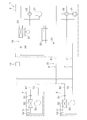
- FIG. 1 is a schematic configuration diagram of an air conditioning system 1 according to an embodiment of the present disclosure.
- FIG. 2 is a perspective view showing a main part of the indoor heat exchanger 52 constituting the air conditioning system 1 of FIG.
- the air conditioning system 1 constitutes a multi-source refrigeration cycle including a heat source side circuit 10 in which a heat source side refrigerant circulates and a use side circuit 30 in which a use side refrigerant circulates, and heats the use side refrigerant and room air. It is a system that performs air conditioning (cooling or heating) of the indoor space by replacing the air conditioner.
- the heat source side circuit 10 mainly includes a heat source side compressor 21, an outdoor heat exchanger 23, and a refrigerant-refrigerant heat exchanger 25.
- an HFC refrigerant such as R32, an HFO refrigerant such as R1234yf, or a mixed refrigerant thereof is sealed as the heat source side refrigerant.
- the heat source side circuit 10 includes a heat source side flow switching device 22 and a heat source side decompressor 24.
- the heat source side compressor 21 is a device that compresses the heat source side refrigerant.
- the heat source side compressor 21 is, for example, a compressor that drives a compression element such as a rotary or a scroll by a drive mechanism such as a motor or an engine.
- the heat-source-side flow switching device 22 allows the outdoor heat exchanger 23 to function as a heat-source-side refrigerant radiator and the refrigerant-refrigerant heat exchanger 25 to function as a heat-source-side refrigerant evaporator (FIG. 1). ),
- the outdoor heat exchanger 23 functions as an evaporator for the heat source-side refrigerant, and the refrigerant-refrigerant heat exchanger 25 functions as a radiator for the heat source-side refrigerant.
- This is a device that switches between a second state (see a broken line of the heat source side flow path switching device 22 in FIG. 1).
- the heat source side flow switching device 22 is, for example, a four-way switching valve.
- the heat-source-side flow switching device 22 connects the discharge side of the heat-source-side compressor 21 and the gas side of the outdoor heat exchanger 23, and connects the suction side of the heat-source-side compressor 21 with the refrigerant. Connecting the gas side of the flow path of the refrigerant heat exchanger 25 through which the heat source side refrigerant flows.
- the heat-source-side flow switching device 22 connects the discharge side of the heat-source-side compressor 21 to the gas side of the flow path of the refrigerant-refrigerant heat exchanger 25 through which the heat-source-side refrigerant flows, and The suction side of the side compressor 21 and the gas side of the outdoor heat exchanger 23 are connected.
- the heat-source-side flow switching device 22 is not limited to the four-way switching valve, but may be, for example, a combination of a plurality of valves (such as a solenoid valve or a three-way valve) in the first state and the second state. It may be configured to have a function of switching.
- the outdoor heat exchanger 23 is a device for exchanging heat between the heat source side refrigerant and the outdoor air.
- the outdoor heat exchanger 23 is, for example, a fin-and-tube heat exchanger.
- the outdoor heat exchanger 23 functions as a radiator for a heat source-side refrigerant that uses outdoor air as a cooling source when the heat source-side flow switch 22 is switched to the first state. In the state switched to the second state, it functions as a heat-source-side refrigerant evaporator that uses outdoor air as a heating source.
- the gas side of the outdoor heat exchanger 23 is connected to the heat source side flow switching device 22, and the liquid side is connected to the liquid side of the flow path of the refrigerant-refrigerant heat exchanger 25 through which the heat source side refrigerant flows.
- the heat source side decompressor 24 is a device for decompressing the heat source side refrigerant.
- the heat source side decompressor 24 is, for example, an electric expansion valve.
- the heat source side depressurizer 24 depressurizes the heat source side refrigerant radiated in the outdoor heat exchanger 23 when the heat source side flow switch 22 is switched to the first state, and the heat source side flow switch 22 In the switched state, the heat-source-side refrigerant radiated in the refrigerant-refrigerant heat exchanger 25 is depressurized.
- the heat source side decompressor 24 has one end connected to the liquid side of the outdoor heat exchanger 23 and the other end connected to the liquid side of the flow path of the refrigerant-refrigerant heat exchanger 25 through which the heat source side refrigerant flows. .
- the heat source side decompressor 24 is not limited to the electric expansion valve, but may be another expansion valve, a capillary tube, or an expander, for example.
- the refrigerant-refrigerant heat exchanger 25 is a device for exchanging heat between the heat source side refrigerant and the use side refrigerant.
- the refrigerant-refrigerant heat exchanger 25 is, for example, a plate-type or double-tube heat exchanger.
- the plate-type or double-pipe heat exchanger is suitable for heat exchange between two refrigerants (here, a heat-source-side refrigerant and a use-side refrigerant), and a fin that exchanges heat between the refrigerant and air. It is a small heat exchanger compared to a large heat exchanger such as an and tube type heat exchanger.
- the refrigerant-refrigerant heat exchanger 25 functions as a refrigerant evaporator that uses the use-side refrigerant as a heating source when the heat-source-side flow switching device 22 is switched to the first state. In the state switched to the second state, it functions as a refrigerant radiator using the use-side refrigerant as a cooling source.
- the gas side of the flow path of the heat-source-side refrigerant in the refrigerant-refrigerant heat exchanger 25 is connected to the heat-source-side flow switch 22, and the flow path of the refrigerant-refrigerant heat exchanger 25 through which the heat-source-side refrigerant flows Is connected to a heat source side decompressor 24.
- the use side circuit 30 includes a use side compressor 31, a refrigerant-refrigerant heat exchanger 25, and a plurality of indoor heat exchangers 52.
- the use side circuit 30 is filled with carbon dioxide as a use side refrigerant.
- the use-side circuit 30 includes a use-side flow switching device 32, a use-side pressure reducer 33, and an indoor pressure reducer 51 corresponding to each of the plurality of indoor heat exchangers 52.
- the refrigerant may be in a supercritical state (a state in which a gas state and a liquid state cannot be distinguished) during the refrigeration cycle.
- a refrigerant R410A, R32, etc.
- the use side compressor 31 is a device that compresses the use side refrigerant.
- the use-side compressor 31 is, for example, a compressor that drives a compression element such as a rotary or a scroll by a drive mechanism such as a motor or an engine.
- the usage-side flow switching device 32 includes a first state in which the refrigerant-refrigerant heat exchanger 25 functions as a radiator for the usage-side refrigerant (see a solid line of the usage-side flow switching device 32 in FIG. 1); This is a device that switches between a second state in which the heat exchanger 25 functions as an evaporator for the usage-side refrigerant (see the broken line of the usage-side flow switching device 32 in FIG. 1).
- the use-side flow path switch 32 causes the indoor heat exchanger 52 to function as an evaporator for the use-side refrigerant
- the second state uses the indoor heat exchanger 52 as a radiator for the use-side refrigerant. Let it work.
- the use-side flow switching device 32 is, for example, a four-way switching valve.
- the use-side flow switching device 32 connects the discharge side of the use-side compressor 31 and the gas side of the flow passage of the use-side refrigerant in the refrigerant-refrigerant heat exchanger 25, and The suction side of the use side compressor 31 and the gas side of the indoor heat exchanger 52 are connected.
- the use-side flow switching device 32 connects the discharge side of the use-side compressor 31 and the gas side of the indoor heat exchanger 52, and connects the suction side of the use-side compressor 31 to the refrigerant-refrigerant.
- the liquid side of the flow path in which the use side refrigerant flows in the heat exchanger 25 is connected.
- the use-side flow switching device 32 is not limited to a four-way switching valve, and may be, for example, a combination of a plurality of valves (such as a solenoid valve or a three-way valve) to switch between the first state and the second state. It may be configured to have a function of switching.
- the refrigerant-refrigerant heat exchanger 25 is a device for exchanging heat between the heat source side refrigerant and the use side refrigerant as described above.
- the refrigerant-refrigerant heat exchanger 25 converts the heat-source-side refrigerant into a cooling source in a state where the heat-source-side flow switching device 22 is switched to the first state and the use-side flow switching device 32 is switched to the first state.
- the heat source side refrigerant is This is a device that functions as an evaporator for the use-side refrigerant that serves as a heating source.
- the gas side of the flow passage of the use-side refrigerant in the refrigerant-refrigerant heat exchanger 25 is connected to the use-side flow switching device 32, and the flow passage of the refrigerant-refrigerant heat exchanger 25 through which the use-side refrigerant flows Is connected to the liquid side of the indoor heat exchanger 52.
- the use side decompressor 33 is a device that decompresses the use side refrigerant.
- the use side pressure reducer 33 is, for example, an electric expansion valve.
- the use-side pressure reducer 33 is in a state where the use-side flow path switching device 32 is switched to the first state, is in a fully opened state or an almost open state, and has radiated heat in the refrigerant-refrigerant heat exchanger 25. Is reduced as much as possible, and in a state where the use-side flow switching device 32 is switched to the second state, the use-side refrigerant sent from the indoor decompressor 51 is decompressed.
- the use side decompressor 33 has one end connected to the liquid side of the flow path of the use side refrigerant in the refrigerant-refrigerant heat exchanger 25 and the other end connected to the indoor decompressor 51.
- the use side decompressor 33 is not limited to the electric expansion valve, but may be another expansion valve, a capillary tube, or an expander, for example.
- the indoor decompressor 51 is a device that decompresses the use-side refrigerant.
- the indoor decompressor 51 is, for example, an electric expansion valve.
- the indoor decompressor 51 decompresses the use-side refrigerant radiated in the refrigerant-refrigerant heat exchanger 25 when the use-side flow switching device 32 is switched to the first state. In the state switched between the two states, the use-side refrigerant radiated in the indoor heat exchanger 52 is depressurized.
- the indoor pressure reducer 51 has one end connected to the use side pressure reducer 33 and the other end connected to the liquid side of the indoor heat exchanger 52.
- the indoor heat exchanger 52 is a device for exchanging heat between the use-side refrigerant and the indoor air.
- the indoor heat exchanger 52 is, for example, a fin-and-tube heat exchanger.
- a fin-and-tube type heat exchanger having a large number of circular heat transfer tubes 54 and a large number of heat transfer fins 55 is used.
- the indoor heat exchanger 52 functions as a radiator of a usage-side refrigerant that uses indoor air as a cooling source when the usage-side flow switching device 32 is switched to the first state. In the state switched to the second state, it functions as an evaporator for the use-side refrigerant using room air as a heating source.
- the gas side of the indoor heat exchanger 52 is connected to the use side switching device 32, and the liquid side is connected to the indoor decompressor 51.
- the components of the heat source side circuit 10 and the use side circuit 30 are provided in the heat transfer unit 2 and the plurality of indoor units 5.
- Each of the indoor units 5 is provided corresponding to the indoor heat exchanger 52.
- the heat transfer unit 2 is disposed outside the room.
- the heat transfer unit 2 includes the heat source side circuit 10 including the refrigerant-refrigerant heat exchanger 25 and the use side compressor 31 and the use side flow path switching unit 32 of the use side circuit 30. Further, the use side decompressor 33 of the use side circuit 30 is also provided in the heat transfer unit 2.
- the heat transfer unit 2 is provided with an outdoor fan 26 for sending outdoor air to the outdoor heat exchanger 23.
- the outdoor fan 26 is a fan that drives a blowing element such as a propeller fan by a driving mechanism such as a motor.
- the indoor unit 5 is arranged indoors.
- the indoor heat exchanger 52 of the use side circuit 30 is provided in the indoor unit 5.
- the indoor decompressor 51 of the use side circuit 30 is also provided in the indoor unit 5.
- the indoor unit 5 is provided with an indoor fan 53 for sending indoor air to the indoor heat exchanger 52.
- the indoor fan 53 is a fan that drives a blowing element such as a centrifugal fan or a multiblade fan by a driving mechanism such as a motor.
- the indoor unit 5 is provided with a refrigerant sensor 11 for detecting leakage of the use-side refrigerant.
- the refrigerant sensor 11 detects whether or not the concentration of carbon dioxide as the use-side refrigerant is equal to or higher than a predetermined concentration.
- the indoor unit 5 is provided with an alarm device 12 for notifying that the use-side refrigerant has leaked when the use-side refrigerant has leaked.
- the alarm device 12 is one of the safety measures to be taken when leakage of carbon dioxide as the use-side refrigerant occurs.
- the alarm device 12 issues a notification that the usage-side refrigerant has leaked.
- the alarm device 12 a device that performs notification of the leakage of the usage-side refrigerant by sound and light is used.
- the refrigerant sensor 11 and the alarm device 12 are provided in the indoor unit 5, but are not limited to this, and are used for operating the indoor space where the indoor unit 5 is air-conditioned and the indoor unit 5. May be provided on a remote controller or the like. Further, the refrigerant sensor 11 and the alarm device 12 may be provided separately.
- the use-side liquid refrigerant communication pipe 6 is a part of a pipe connecting between the refrigerant-refrigerant heat exchanger 25 and the indoor heat exchanger 52.
- the use-side liquid refrigerant communication pipe 6 is a pipe that connects between the use-side pressure reducer 33 and the indoor pressure reducer 51.
- the use-side liquid refrigerant communication pipe 6 mainly includes a use-side liquid refrigerant communication branch pipe 62 connected to each of the indoor units 5, a portion where the use-side liquid refrigerant communication branch pipe 62 is all joined, and the heat transfer unit 2. And a utilization-side liquid refrigerant communication mother pipe 61 for connecting between them.
- the use side gas refrigerant communication pipe 7 is a part of a pipe connecting between the use side compressor 31 and the indoor heat exchanger 52.
- the use-side gas refrigerant communication pipe 7 is a pipe that connects the use-side flow switching device 32 and the gas side of the indoor heat exchanger 52.
- the use-side gas refrigerant communication pipe 7 is mainly composed of a use-side gas refrigerant communication branch pipe 72 connected to each of the indoor units 5, a portion where the use-side gas refrigerant communication branch pipes 72 are all joined, and the heat transfer unit 2. And a utilization-side gas refrigerant communication mother pipe 71 that connects between them.
- the components of the heat transfer unit 2 and the indoor unit 5 are controlled by the control unit 19.
- the control unit 19 is configured such that a control board and the like provided in the heat transfer unit 2 and the indoor unit 5 are connected by communication.
- the control unit 19 is illustrated at a position away from the heat transfer unit 2, the indoor unit 5, and the like for convenience.
- the control unit 19 controls the components 11, 12, 21, 22, 24, 26, 31, 32, 33, 51, and 53 of the air conditioning system 1, that is, the operation control of the entire air conditioning system 1. It is supposed to do.
- the air conditioning system 1 can perform a cooling operation for cooling indoor air and a heating operation for heating indoor air for indoor air conditioning.
- the alarm device 12 notifies that the use-side refrigerant has leaked. Note that the cooling operation, the heating operation, and the operation when the use-side refrigerant leaks are performed by the control unit 19.
- the cooling operation When the cooling operation is performed, for example, when all of the indoor units 5 perform the cooling operation (that is, the operation in which all of the indoor heat exchangers 52 function as evaporators for the use-side refrigerant to cool the indoor air), the heat source The side flow switch 22 is switched to the first state (see the solid line of the heat source side flow switch 22 in FIG. 1), and the use side flow switch 32 is in the first state (use side flow in FIG. 1). (See the solid line of the road switcher 32).
- the heat-source-side refrigerant discharged from the heat-source-side compressor 21 is sent to the outdoor heat exchanger 23 through the heat-source-side flow switching device 22.
- the heat-source-side refrigerant sent to the outdoor heat exchanger 23 is cooled by performing heat exchange with the outdoor air supplied by the outdoor fan 26 in the outdoor heat exchanger 23 functioning as a radiator of the heat-source-side refrigerant. Condenses.
- the refrigerant that has radiated heat in the outdoor heat exchanger 23 is sent to the refrigerant-refrigerant heat exchanger 25 after being decompressed by the heat source side decompressor 24.
- the heat-source-side refrigerant sent to the refrigerant-refrigerant heat exchanger 25 evaporates by being heated by exchanging heat with the use-side refrigerant in the refrigerant-refrigerant heat exchanger 25 functioning as an evaporator of the heat source-side refrigerant. .
- the heat-source-side refrigerant evaporated in the refrigerant-refrigerant heat exchanger 25 is drawn into the heat-source-side compressor 21 through the heat-source-side flow switching device 22, and is discharged from the heat-source-side compressor 21 again.
- the use-side refrigerant discharged from the use-side compressor 31 is sent to the refrigerant-refrigerant heat exchanger 25 through the use-side flow switching device 32.
- the use-side refrigerant sent to the refrigerant-refrigerant heat exchanger 25 is cooled by exchanging heat with the heat source-side refrigerant in the refrigerant-refrigerant heat exchanger 25 functioning as an evaporator for the use-side refrigerant.
- the use-side refrigerant that has radiated heat in the refrigerant-refrigerant heat exchanger 25 is sent to the use-side liquid refrigerant communication pipe 6 through the use-side medium pressure reducer 33.
- the use-side refrigerant sent to the use-side liquid medium communication pipe 6 is sent to the indoor heat exchanger 52 after being depressurized by the indoor pressure reducer 51.
- the use side refrigerant sent to the indoor heat exchanger 52 is cooled by performing heat exchange with the indoor air supplied by the indoor fan 53 in the indoor heat exchanger 52 functioning as an evaporator of the use side refrigerant. Evaporate. Thereby, the cooling operation for cooling the indoor air is performed.
- the use-side refrigerant evaporated in the indoor heat exchanger 52 is sent to the use-side gas refrigerant communication pipe 7.
- the use-side refrigerant sent to the use-side gas refrigerant communication pipe 7 is sucked into the use-side compressor 31 through the use-side flow switching device 32 and is discharged from the use-side compressor 31 again.
- the heating operation is performed, for example, when all the indoor units 5 perform the heating operation (that is, when all the indoor heat exchangers 52 function as radiators of the use-side refrigerant to heat the indoor air), the heat source The side flow switch 22 is switched to the second state (see the broken line of the heat source side flow switch 22 in FIG. 1), and the use side flow switch 32 is in the second state (use side flow in FIG. 1). (See the broken line of the road switcher 32).
- the heat-source-side refrigerant discharged from the heat-source-side compressor 21 is sent to the refrigerant-refrigerant heat exchanger 25 through the heat-source-side flow switching device 22.
- the heat-source-side refrigerant sent to the refrigerant-refrigerant heat exchanger 25 is condensed by performing heat exchange with the use-side refrigerant and cooling in the refrigerant-refrigerant heat exchanger 25 that functions as a radiator of the heat source-side refrigerant. .
- the heat-source-side refrigerant that has radiated heat in the refrigerant-refrigerant heat exchanger 25 is sent to the outdoor heat exchanger 23 after being decompressed by the heat-source-side decompressor 24.
- the heat-source-side refrigerant sent to the outdoor heat exchanger 23 is heated by exchanging heat with the outdoor air supplied by the outdoor fan 26 in the outdoor heat exchanger 23 functioning as an evaporator for the heat-source-side refrigerant. Evaporate.
- the heat-source-side refrigerant evaporated in the outdoor heat exchanger 23 is drawn into the heat-source-side compressor 21 through the heat-source-side flow switching device 22, and is discharged from the heat-source-side compressor 21 again.
- the usage-side refrigerant discharged from the usage-side compressor 31 is sent to the usage-side gas refrigerant communication pipe 7 through the usage-side flow switching device 32.
- the use-side refrigerant sent to the use-side gas refrigerant communication pipe 7 is sent to the indoor heat exchanger 52.
- the use-side refrigerant sent to the indoor heat exchanger 52 is cooled by performing heat exchange with the indoor air supplied by the indoor fan 53 in the indoor heat exchanger 52 functioning as a radiator of the use-side refrigerant. Thereby, the heating operation for heating the indoor air is performed.
- the use-side refrigerant that has radiated heat in the indoor heat exchanger 52 is sent to the use-side liquid refrigerant communication pipe 6 after being decompressed by the indoor decompressor 51.
- the use-side refrigerant sent to the use-side liquid refrigerant communication pipe 6 is further decompressed by the use-side decompressor 33 and then sent to the refrigerant-refrigerant heat exchanger 25.
- the use-side refrigerant sent to the refrigerant-refrigerant heat exchanger 25 evaporates by being heated by exchanging heat with the heat source-side refrigerant in the refrigerant-refrigerant heat exchanger 25 functioning as an evaporator of the use-side refrigerant. .
- the use-side refrigerant evaporated in the refrigerant-refrigerant heat exchanger 25 is drawn into the use-side compressor 31 through the use-side flow switching device 32, and is discharged from the use-side compressor 31 again.
- the refrigerant sensor 11 detects the leakage of the use-side refrigerant, and the alarm device 12 notifies that the use-side refrigerant has leaked.
- the concentration level of carbon dioxide can be reduced to a concentration level at which one safety measure to be taken when leakage of carbon dioxide as a use-side refrigerant occurs can be taken.
- the alarm device 12 is selected and provided as a safety measure.
- FIG. 3 is an explanatory diagram of a piping system that connects the units 2, 5a to 5j that constitute the air conditioning system 1 of FIG.
- FIG. 4 is a table showing the relationship between the rated refrigeration capacity and the diameter of the refrigerant communication pipe when carbon dioxide is used as the refrigerant.
- FIG. 5 is a diagram showing the relationship between the configuration of the air conditioning system (one-way refrigeration cycle A and two-way refrigeration cycle A) and the amount of carbon dioxide as a refrigerant.
- the refrigerant is a refrigerant. It is necessary to take safety measures according to the concentration level of carbon dioxide that may reach the indoor space when leaked from the circuit.
- the concentration levels of good carbon dioxide without providing a safety is a condition that the indoor space 1 m 3 per 0.074kg following safety measures may density level only one, indoor space 1 m 3 per 0. greater than 074Kg, and a condition that less 0.18 kg, safety measures more than the required concentration levels, a condition of greater interior space 1 m 3 per 0.18 kg.
- a safety measure in addition to an alarm device for notifying that the refrigerant has leaked, a shut-off device that shuts off the circulation of the refrigerant when the refrigerant has leaked, and an indoor heat exchanger when the refrigerant has leaked.
- a ventilation device that ventilates a space that is air-conditioned by indoor air that has undergone heat exchange.
- the floor area of the air conditioning space per 2.8 kW of rated refrigeration capacity is 20 m 2
- an air conditioning system with a rated refrigeration capacity of 28 kW is installed in a plurality of air conditioning spaces with a total floor area of 200 m 2. Then, when carbon dioxide as a refrigerant leaks into the air-conditioned space having the smallest space volume among the plurality of air-conditioned spaces, the amount of the refrigerant (carbon dioxide) that can be reduced by one or less safety measure is calculated.
- the refrigerant amount may be larger than 7.9 kg.
- safety measures should be taken. In some cases, it can be done with less than one. In that sense, the value of the refrigerant amount calculated here is the safest condition, and if this refrigerant amount condition is satisfied, it is possible to perform one or less safety measures in virtually all air conditioning systems. You can say that you can.
- the heat transfer unit 2 includes 10 indoor units 5 (5a to 5j) having a rated refrigerating capacity of 2.8 kW.
- the connected configuration will be described as an example.
- the use-side refrigerant communication mother pipes 61 and 71 are 50 m and the sum of the use-side refrigerant communication branch pipes 62 and 72 (62a to 62j, 72a to 72j). Is 20 m.
- the pipe diameters of the use side refrigerant communication pipes 6 and 7 are selected and used according to the rated refrigeration capacity.
- a pipe having a nominal diameter of 2.5 / 8 inch is used as the use side liquid refrigerant communication main pipe 61, and a pipe having a nominal diameter of 1.5 / 8 inch is used as the use side liquid refrigerant communication branch pipe 62.
- a pipe having a nominal diameter of 5/8 inch is used as the usage-side gas refrigerant communication main pipe 71, and a pipe having a nominal diameter of 2.5 / 8 inch is used as the usage-side gas refrigerant communication branch pipe 72.
- a pipe having a nominal diameter of 2.5 / 8 inch or less is used as the use-side liquid refrigerant communication pipe 6, and the use-side gas refrigerant communication pipe 7 is used.
- the same refrigerating capacity as the air conditioning system 1 (10 indoor units with a rated refrigerating capacity of 2.8 kW) and the same as the air conditioning system 1
- the refrigerant amount is 9.0 kg ( (See the value of the one-way refrigeration cycle A in FIG. 5).
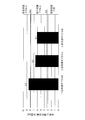
- the amount of the use side refrigerant (carbon dioxide) sealed in the use side circuit 30 of the air conditioning system 1 of the binary refrigeration cycle is calculated based on the amount of the refrigerant, the one-way refrigeration using carbon dioxide as the refrigerant is performed. As compared with the air conditioning system of the cycle, the amount is 2.4 kg less and the amount of the use side refrigerant is 6.6 kg (see the value of the binary refrigeration cycle A in FIG. 5).
- the amount of the use side refrigerant (carbon dioxide) sealed in the use side circuit 30 of the air conditioning system 1 of the binary refrigeration cycle can be reduced because of the large outdoor heat exchange between the refrigerant and the outdoor air.
- An exchanger is provided in the heat source side circuit 10 that does not have the plurality of indoor heat exchangers 52, and the use side circuit 30 that uses carbon dioxide as the use side refrigerant includes a small refrigerant-refrigerant heat exchanger. This is because 25 may be provided.
- the amount of refrigerant (carbon dioxide) sealed in the refrigerant circuit is larger than 7.9 kg, so two or more safety measures are required. It is.
- the amount of the usage-side refrigerant (carbon dioxide) sealed in the usage-side circuit 30 can be 7.9 kg or less, so that only one safety measure can be completed. .
- the alarm device 12 that issues a notification that the use-side refrigerant has leaked when the use-side refrigerant has leaked is provided.
- the alarm device 12 it is necessary to use a device that provides notification that the use-side refrigerant has leaked by sound and light, but it is not necessary to provide other safety measures (blocking device or ventilation device). Therefore, the cost is low and the construction is easy.
- the air conditioning system 1 constitutes a binary refrigeration cycle including the heat source side circuit 10 and the use side circuit 30.
- the heat source side circuit 10 includes a heat source side compressor 21 for compressing the heat source side refrigerant, an outdoor heat exchanger 23 for exchanging heat between the heat source side refrigerant and outdoor air, and a refrigerant for exchanging heat between the heat source side refrigerant and the use side refrigerant.
- the use side circuit 30 includes a use side compressor 31 for compressing the use side refrigerant, a refrigerant-refrigerant heat exchanger 25, and a plurality of indoor heat exchangers 52 for exchanging heat between the use side refrigerant and room air.
- Carbon dioxide is sealed as a use-side refrigerant.
- one of the alarm device 12, the alarm device 12, and the ventilation device is provided among the alarm device 12, the shut-off device, and the ventilation device. ing.
- the air conditioning system of the unitary refrigeration cycle using carbon dioxide as a refrigerant has an outdoor heat exchanger that performs heat exchange between carbon dioxide as refrigerant and outdoor air in a refrigerant circuit.
- the volume occupied by the outdoor heat exchanger is quite large.
- the air conditioning system of the unitary refrigeration cycle that uses carbon dioxide as the refrigerant is less efficient than conventional refrigerants (such as HFC refrigerants) due to its physical properties.
- the outdoor heat exchanger functions as a refrigerant radiator. This is remarkable in an operation (cooling operation) in which the indoor heat exchanger functions as an evaporator for the refrigerant.
- the heat transfer area of the outdoor heat exchanger is increased, or the intermediate cooling for cooling the refrigerant during the compression process.
- a device such as a supercooler for further cooling the refrigerant radiated in the heat exchanger or the outdoor heat exchanger is employed.
- the amount of carbon dioxide as the refrigerant sealed in the refrigerant circuit increases, and it is difficult to reduce safety measures.
- the use side circuit 30 having the plurality of indoor heat exchangers 52 and containing carbon dioxide as the use side refrigerant, and the use side circuit 30 through the refrigerant-refrigerant heat exchanger 25 And a heat source side circuit 10 in which a heat source side refrigerant that exchanges heat with the refrigerant is enclosed. Therefore, here, unlike the one-way refrigeration cycle using carbon dioxide as the refrigerant, the outdoor heat exchanger 23 that performs heat exchange between the refrigerant and the outdoor air is a heat source that does not have the plurality of indoor heat exchangers 52.
- a use-side circuit 30 provided in the side circuit 10 and using carbon dioxide as the use-side refrigerant is provided with a refrigerant-refrigerant heat exchanger 25.
- the refrigerant-refrigerant heat exchanger 25 is not a large-sized heat exchanger for performing heat exchange between refrigerant and air, but is suitable for heat exchange between two refrigerants (here, a heat source side refrigerant and a use side refrigerant).
- a small heat exchanger such as a plate or double tube heat exchanger, can be used.
- the heat source side circuit 10 uses a refrigerant (R32, R1234yf, or the like) having physical properties capable of increasing the efficiency over carbon dioxide.
- R32, R1234yf, or the like a refrigerant having physical properties capable of increasing the efficiency over carbon dioxide.
- the efficiency such as providing an intercooler or a subcooler, the overall efficiency including the use side circuit 30 can be improved.
- the amount of carbon dioxide as the use-side refrigerant sealed in the use-side circuit 30 can be reduced, and the efficiency can be improved. You can also.
- the concentration levels of carbon safety measures concentration levels that can dispense with one (larger than 0.074kg per indoor space 1 m 3, and satisfies the concentration level of less 0.18 kg) so that down to .
- this concentration level is converted into the amount of carbon dioxide as the use-side refrigerant sealed in the use-side circuit 30, it is larger than 3.3 kg and 7.9 kg or less.
- the safety level is reduced to a concentration level at which only one safety measure can be performed, and as described above, any one of the alarm device 12, the ventilation device, and the alarm device 12, the shutoff device, and the ventilation device is used.
- One is provided. That is, here, the number of safety measures is reduced to one, and no interruption device is provided as a safety measure.
- the shutoff device is a device that must be provided in the use side circuit 30, and it is necessary to satisfy the installation standards such as the shutoff performance. Therefore, it is costly and unnecessary to provide the shutoff device as a safety measure. It is effective in construction.
- the alarm device 12 of the alarm device 12 and the ventilation device is provided.
- the alarm device 12 is provided, and the ventilation device is not provided.
- a ventilation device is provided as a safety measure, it is necessary to meet the installation standards such as the amount of ventilation, the number of ventilations, and the position of the ventilation opening. And is effective in construction.
- the refrigerant as the refrigerant sealed in the refrigerant circuit (the use side circuit 30) is used.
- the amount of carbon dioxide By reducing the amount of carbon dioxide, safety measures can be reduced.
- the refrigerant-refrigerant heat exchanger 25 and the indoor heat A pipe having a nominal diameter of 2.5 / 8 inch or less, which is smaller than the conventional pipe, is used as a pipe (use side liquid refrigerant communication pipe 6) connecting to the exchanger 52, and the use side compression of the use side circuit 30 is used.
- a pipe (use side gas refrigerant communication pipe 7) connecting between the unit 31 and the indoor heat exchanger 52 a pipe having a nominal diameter of 5/8 inch or less, which is smaller than the conventional one, is used.
- a pipe having a nominal diameter of 1.5 / 8 inch is used as the use side liquid refrigerant communication pipe 6 when the rated refrigeration capacity is in the range of 2.2 kW to 8.0 kW. In the range of 0.4 kW to 28.0 kW, a pipe having a nominal diameter of 2.5 / 8 inch is used.
- a tube with a nominal diameter of .5 / 8 inch is used.
- the size of a tube usable as a refrigerant tube can be increased. This can contribute to optimization of the refrigerant pipe.
- the indoor heat exchanger 52 not a heat exchanger having a large number of circular heat transfer tubes 54, but a large number of flat heat transfer tubes 56 as shown in FIG. Using a microchannel heat exchanger.
- a fin-and-tube type heat exchanger having a large number of heat transfer tubes 56 and a large number of heat transfer fins 57 is employed as the micro-chan heat heat exchanger, as in FIG. It is not limited.
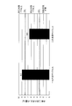
- the volume of the indoor heat exchanger 52 can be reduced, and the amount of the use-side refrigerant sealed in the use-side circuit 30 is reduced by the fin-and-tube type having a large number of heat transfer tubes 54 formed of circular tubes. 0.5 kg less than in the case where the heat exchanger of No. 1 is used, and the amount of the use-side refrigerant is 6.1 kg (see the value of the binary refrigeration cycle B in FIG. 7).
- the indoor heat exchanger 52 is constituted by the micro-channel heat exchanger, the volume of the indoor heat exchanger 52 can be reduced, and thus the indoor heat exchanger 52 is sealed in the use side circuit 30. The amount of the use-side refrigerant can be further reduced.
- the amount of the refrigerant does not become 7.9 kg or less, it is understood that one safety measure cannot be completed as long as the air conditioning system of the unitary refrigeration cycle is adopted.
- the use-side compressor 31 and the refrigerant-refrigerant heat exchanger 25 of the use-side circuit 30 are provided in the heat transfer unit 2 together with the heat source-side circuit 10 (see FIG. 1).
- the amount of the usage-side refrigerant (carbon dioxide) sealed in the usage-side circuit 30 is 6.1 kg in the case of the first modification (when the indoor heat exchanger 52 is configured by a microchannel heat exchanger) ( (See the value of the binary refrigeration cycle B in FIG. 7).
- the heat transfer unit 2 is divided into an outdoor unit 3 and an intermediate unit 4, and the heat transfer unit 2 is connected between the units 3 and 4 via the heat source side refrigerant communication pipes 8 and 9. Are connected.
- the outdoor unit 3 is arranged outside the room. As shown in FIG. 8, portions of the heat source side circuit 10 excluding the refrigerant-refrigerant heat exchanger 25 (the heat source side compressor 21, the heat source side flow switching device 22, the outdoor heat exchanger 23, and the heat source side decompressor). 24) is provided in the outdoor unit 3.
- the refrigerant-refrigerant heat exchanger 25 the heat source side compressor 21, the heat source side flow switching device 22, the outdoor heat exchanger 23, and the heat source side decompressor. 24
- the intermediate unit 4 is arranged at a position close to the branch to the indoor unit 5, as shown in FIG. As shown in FIG. 8, the use-side compressor 31, the use-side flow switching device 32, the refrigerant-refrigerant heat exchanger 25, and the use-side decompressor 33 in the use-side circuit 30 are provided in the intermediate unit 4. .
- the heat-source-side liquid refrigerant communication pipe 8 is a part of a pipe that connects between the outdoor heat exchanger 23 and the refrigerant-refrigerant heat exchanger 25.
- the heat source side liquid refrigerant communication pipe 6 is a pipe connecting between the heat source side decompressor 24 and the liquid side of the flow path of the refrigerant-refrigerant heat exchanger 25 through which the heat source side refrigerant flows.
- the heat source side gas refrigerant communication pipe 9 is a part of a pipe connecting between the heat source side compressor 21 and the refrigerant-refrigerant heat exchanger 25.
- the heat source side gas refrigerant communication pipe 9 is a pipe connecting between the heat source side flow path switching device 22 and the gas side of the flow path of the refrigerant-refrigerant heat exchanger 25 through which the heat source side refrigerant flows. .
- the outdoor heat exchanger 23 is provided in the outdoor unit 3, and the refrigerant-refrigerant heat exchanger 25 is connected to the outdoor unit 3 via the heat source side refrigerant communication pipes 8, 9 through which the heat source side refrigerant flows.
- the indoor heat exchanger 52 is provided in the intermediate unit 4 connected to the intermediate unit 4 via the use-side refrigerant communication pipes 6 and 7 through which the use-side refrigerant flows. ing.
- the intermediate unit 4 provided with the refrigerant-refrigerant heat exchanger 25 can be provided at a position near the branch to the indoor unit 5, for example, from the intermediate unit 4 to the indoor unit 5.
- the length of the use-side refrigerant communication mother tubes 61, 71 of the use-side refrigerant communication tubes 6, 7 can be reduced to 10 m.
- the amount of the use-side refrigerant sealed in the use-side circuit 30 is determined when the refrigerant-refrigerant heat exchanger 25 is provided in the outdoor heat transfer unit 2 (the length of the use-side refrigerant communication mother tubes 61, 71). Is 50 m), and the amount of the use-side refrigerant is 5.0 kg (see the value of the binary refrigeration cycle C in FIG. 10).
- the refrigerant-refrigerant heat exchanger 25 is provided in the intermediate unit 4 different from the outdoor unit 3, the refrigerant-refrigerant heat exchanger 25 is provided at a position close to the indoor unit 5. Accordingly, the amount of the use-side refrigerant sealed in the use-side circuit 30 can be further reduced.
- the present disclosure is widely applicable to an air conditioning system having a plurality of indoor heat exchangers for exchanging heat between carbon dioxide as a refrigerant and indoor air.
Landscapes
- Engineering & Computer Science (AREA)
- Mechanical Engineering (AREA)
- General Engineering & Computer Science (AREA)
- Chemical & Material Sciences (AREA)
- Physics & Mathematics (AREA)
- Thermal Sciences (AREA)
- Combustion & Propulsion (AREA)
- Chemical Kinetics & Catalysis (AREA)
- Air Conditioning Control Device (AREA)
- Air Filters, Heat-Exchange Apparatuses, And Housings Of Air-Conditioning Units (AREA)
Abstract
La présente invention concerne un système de climatisation (1) constituant un cycle frigorifique à plusieurs sources comprenant un circuit (10) côté source de chaleur et un circuit (30) côté utilisation. Le circuit (10) côté source de chaleur comporte un compresseur (21) côté source de chaleur, un échangeur de chaleur extérieur (23) destiné à effectuer un échange de chaleur entre un fluide frigorigène côté source de chaleur et l'air extérieur, et un échangeur de chaleur fluide frigorigène-fluide frigorigène (25) destiné à effectuer un échange de chaleur entre le fluide frigorigène côté source de chaleur et un fluide frigorigène côté utilisation. Le circuit (30) côté utilisation comporte un compresseur (31) côté utilisation, un échangeur de chaleur fluide frigorigène-fluide frigorigène (25), et une pluralité d'échangeurs de chaleur intérieurs (52) destinés à effectuer un échange de chaleur entre le fluide frigorigène côté utilisation et l'air intérieur, et du dioxyde de carbone étant renfermé en tant que fluide frigorigène côté utilisation. La quantité du fluide frigorigène côté utilisation, renfermé dans le circuit (30) côté utilisation, est égale ou inférieure à 7,9 kg.
Priority Applications (2)
| Application Number | Priority Date | Filing Date | Title |
|---|---|---|---|
| JP2020527411A JPWO2020004108A1 (ja) | 2018-06-25 | 2019-06-17 | 空気調和システム |
| EP19824978.1A EP3812662A4 (fr) | 2018-06-25 | 2019-06-17 | Système de climatisation |
Applications Claiming Priority (2)
| Application Number | Priority Date | Filing Date | Title |
|---|---|---|---|
| JP2018-119780 | 2018-06-25 | ||
| JP2018119780 | 2018-06-25 |
Publications (1)
| Publication Number | Publication Date |
|---|---|
| WO2020004108A1 true WO2020004108A1 (fr) | 2020-01-02 |
Family
ID=68986483
Family Applications (1)
| Application Number | Title | Priority Date | Filing Date |
|---|---|---|---|
| PCT/JP2019/023941 Ceased WO2020004108A1 (fr) | 2018-06-25 | 2019-06-17 | Système de climatisation |
Country Status (3)
| Country | Link |
|---|---|
| EP (1) | EP3812662A4 (fr) |
| JP (1) | JPWO2020004108A1 (fr) |
| WO (1) | WO2020004108A1 (fr) |
Cited By (7)
| Publication number | Priority date | Publication date | Assignee | Title |
|---|---|---|---|---|
| WO2020250953A1 (fr) * | 2019-06-12 | 2020-12-17 | ダイキン工業株式会社 | Conditionneur d'air |
| WO2020250952A1 (fr) * | 2019-06-12 | 2020-12-17 | ダイキン工業株式会社 | Conditionneur d'air |
| JPWO2021065944A1 (fr) * | 2019-09-30 | 2021-04-08 | ||
| CN113432196A (zh) * | 2021-06-21 | 2021-09-24 | 深圳市科信通信技术股份有限公司 | 空调系统 |
| US20220235982A1 (en) * | 2019-08-07 | 2022-07-28 | Mitsubishi Electric Corporation | Refrigeration cycle apparatus |
| JP7235998B1 (ja) | 2021-09-30 | 2023-03-09 | ダイキン工業株式会社 | カスケードユニットおよび冷凍サイクル装置 |
| JP7606121B1 (ja) | 2023-07-03 | 2024-12-25 | ダイキン工業株式会社 | 冷凍装置 |
Citations (6)
| Publication number | Priority date | Publication date | Assignee | Title |
|---|---|---|---|---|
| JP2009139012A (ja) * | 2007-12-06 | 2009-06-25 | Mitsubishi Electric Corp | 冷凍空調装置 |
| JP2011106697A (ja) * | 2009-11-13 | 2011-06-02 | Mitsubishi Electric Corp | 空調室内機 |
| WO2011099063A1 (fr) | 2010-02-10 | 2011-08-18 | 三菱電機株式会社 | Dispositif de climatisation |
| JP2013164246A (ja) * | 2012-02-13 | 2013-08-22 | Mitsubishi Electric Corp | 熱交換器及び冷凍空調装置 |
| JP2014020673A (ja) * | 2012-07-18 | 2014-02-03 | Mitsubishi Electric Corp | 冷凍装置 |
| WO2016203507A1 (fr) * | 2015-06-15 | 2016-12-22 | 三菱電機株式会社 | Dispositif à cycle de réfrigération |
Family Cites Families (1)
| Publication number | Priority date | Publication date | Assignee | Title |
|---|---|---|---|---|
| US20130233006A1 (en) * | 2011-01-26 | 2013-09-12 | Mitsubishi Electric Corporation | Air-conditioning apparatus |
-
2019
- 2019-06-17 WO PCT/JP2019/023941 patent/WO2020004108A1/fr not_active Ceased
- 2019-06-17 JP JP2020527411A patent/JPWO2020004108A1/ja active Pending
- 2019-06-17 EP EP19824978.1A patent/EP3812662A4/fr not_active Withdrawn
Patent Citations (6)
| Publication number | Priority date | Publication date | Assignee | Title |
|---|---|---|---|---|
| JP2009139012A (ja) * | 2007-12-06 | 2009-06-25 | Mitsubishi Electric Corp | 冷凍空調装置 |
| JP2011106697A (ja) * | 2009-11-13 | 2011-06-02 | Mitsubishi Electric Corp | 空調室内機 |
| WO2011099063A1 (fr) | 2010-02-10 | 2011-08-18 | 三菱電機株式会社 | Dispositif de climatisation |
| JP2013164246A (ja) * | 2012-02-13 | 2013-08-22 | Mitsubishi Electric Corp | 熱交換器及び冷凍空調装置 |
| JP2014020673A (ja) * | 2012-07-18 | 2014-02-03 | Mitsubishi Electric Corp | 冷凍装置 |
| WO2016203507A1 (fr) * | 2015-06-15 | 2016-12-22 | 三菱電機株式会社 | Dispositif à cycle de réfrigération |
Non-Patent Citations (1)
| Title |
|---|
| See also references of EP3812662A4 * |
Cited By (14)
| Publication number | Priority date | Publication date | Assignee | Title |
|---|---|---|---|---|
| WO2020250952A1 (fr) * | 2019-06-12 | 2020-12-17 | ダイキン工業株式会社 | Conditionneur d'air |
| US12140358B2 (en) | 2019-06-12 | 2024-11-12 | Daikin Industries, Ltd. | Refrigerant cycle system |
| WO2020250953A1 (fr) * | 2019-06-12 | 2020-12-17 | ダイキン工業株式会社 | Conditionneur d'air |
| US20220235982A1 (en) * | 2019-08-07 | 2022-07-28 | Mitsubishi Electric Corporation | Refrigeration cycle apparatus |
| WO2021065944A1 (fr) * | 2019-09-30 | 2021-04-08 | ダイキン工業株式会社 | Appareil de climatisation |
| JPWO2021065944A1 (fr) * | 2019-09-30 | 2021-04-08 | ||
| CN113432196A (zh) * | 2021-06-21 | 2021-09-24 | 深圳市科信通信技术股份有限公司 | 空调系统 |
| JP7235998B1 (ja) | 2021-09-30 | 2023-03-09 | ダイキン工業株式会社 | カスケードユニットおよび冷凍サイクル装置 |
| WO2023054273A1 (fr) * | 2021-09-30 | 2023-04-06 | ダイキン工業株式会社 | Unité en cascade et dispositif à cycle frigorifique |
| JP2023051376A (ja) * | 2021-09-30 | 2023-04-11 | ダイキン工業株式会社 | カスケードユニットおよび冷凍サイクル装置 |
| US12222146B2 (en) | 2021-09-30 | 2025-02-11 | Daikin Industries, Ltd. | Cascade unit and refrigeration cycle apparatus |
| JP7606121B1 (ja) | 2023-07-03 | 2024-12-25 | ダイキン工業株式会社 | 冷凍装置 |
| WO2025009323A1 (fr) * | 2023-07-03 | 2025-01-09 | ダイキン工業株式会社 | Dispositif de réfrigération |
| JP2025007799A (ja) * | 2023-07-03 | 2025-01-17 | ダイキン工業株式会社 | 冷凍装置 |
Also Published As
| Publication number | Publication date |
|---|---|
| EP3812662A1 (fr) | 2021-04-28 |
| EP3812662A4 (fr) | 2021-08-04 |
| JPWO2020004108A1 (ja) | 2021-07-15 |
Similar Documents
| Publication | Publication Date | Title |
|---|---|---|
| WO2020004108A1 (fr) | Système de climatisation | |
| CN102483273B (zh) | 空气调节装置 | |
| CN102597657B (zh) | 空气调节装置 | |
| CN102770715B (zh) | 空气调节装置 | |
| EP1703230B1 (fr) | Appareil de climatisation d'air à fonctions multiples et son procédé de commande | |
| CN102483249B (zh) | 空气调节装置 | |
| CN102753914B (zh) | 空气调节装置和空气调节热水供给系统 | |
| CN103080668B (zh) | 空气调节装置 | |
| CN107076467B (zh) | 空气调节装置 | |
| CN102844630A (zh) | 空调热水供给复合系统 | |
| CN104838218A (zh) | 空调装置 | |
| CN103620325A (zh) | 空气调节装置 | |
| WO2016079834A1 (fr) | Dispositif de conditionnement d'air | |
| JPWO2019198175A1 (ja) | 冷凍サイクル装置 | |
| JP5277854B2 (ja) | 空気調和装置 | |
| JP6576603B1 (ja) | 空気調和装置 | |
| CN114450528B (zh) | 空调机 | |
| WO2023002522A1 (fr) | Dispositif de climatisation et procédé d'installation de dispositif de climatisation | |
| JP2002243319A (ja) | 空気調和装置 | |
| WO2017119138A1 (fr) | Dispositif de climatisation | |
| JP6537603B2 (ja) | 空気調和装置 | |
| JP2004170048A (ja) | 空気調和装置 | |
| JP7660334B2 (ja) | 冷凍サイクル装置 | |
| WO2021065677A1 (fr) | Climatiseur | |
| US12480692B2 (en) | Refrigeration cycle system, heat source unit, and refrigeration cycle apparatus |
Legal Events
| Date | Code | Title | Description |
|---|---|---|---|
| 121 | Ep: the epo has been informed by wipo that ep was designated in this application |
Ref document number: 19824978 Country of ref document: EP Kind code of ref document: A1 |
|
| ENP | Entry into the national phase |
Ref document number: 2020527411 Country of ref document: JP Kind code of ref document: A |
|
| NENP | Non-entry into the national phase |
Ref country code: DE |
|
| ENP | Entry into the national phase |
Ref document number: 2019824978 Country of ref document: EP Effective date: 20210125 |