WO2020004140A1 - Verre en plaque - Google Patents
Verre en plaque Download PDFInfo
- Publication number
- WO2020004140A1 WO2020004140A1 PCT/JP2019/024077 JP2019024077W WO2020004140A1 WO 2020004140 A1 WO2020004140 A1 WO 2020004140A1 JP 2019024077 W JP2019024077 W JP 2019024077W WO 2020004140 A1 WO2020004140 A1 WO 2020004140A1
- Authority
- WO
- WIPO (PCT)
- Prior art keywords
- less
- glass plate
- content
- glass
- inclined surface
- Prior art date
- Legal status (The legal status is an assumption and is not a legal conclusion. Google has not performed a legal analysis and makes no representation as to the accuracy of the status listed.)
- Ceased
Links
Images


Classifications
-
- C—CHEMISTRY; METALLURGY
- C03—GLASS; MINERAL OR SLAG WOOL
- C03C—CHEMICAL COMPOSITION OF GLASSES, GLAZES OR VITREOUS ENAMELS; SURFACE TREATMENT OF GLASS; SURFACE TREATMENT OF FIBRES OR FILAMENTS MADE FROM GLASS, MINERALS OR SLAGS; JOINING GLASS TO GLASS OR OTHER MATERIALS
- C03C3/00—Glass compositions
- C03C3/04—Glass compositions containing silica
- C03C3/076—Glass compositions containing silica with 40% to 90% silica, by weight
- C03C3/078—Glass compositions containing silica with 40% to 90% silica, by weight containing an oxide of a divalent metal, e.g. an oxide of zinc
-
- C—CHEMISTRY; METALLURGY
- C03—GLASS; MINERAL OR SLAG WOOL
- C03C—CHEMICAL COMPOSITION OF GLASSES, GLAZES OR VITREOUS ENAMELS; SURFACE TREATMENT OF GLASS; SURFACE TREATMENT OF FIBRES OR FILAMENTS MADE FROM GLASS, MINERALS OR SLAGS; JOINING GLASS TO GLASS OR OTHER MATERIALS
- C03C3/00—Glass compositions
- C03C3/04—Glass compositions containing silica
- C03C3/076—Glass compositions containing silica with 40% to 90% silica, by weight
- C03C3/083—Glass compositions containing silica with 40% to 90% silica, by weight containing aluminium oxide or an iron compound
- C03C3/085—Glass compositions containing silica with 40% to 90% silica, by weight containing aluminium oxide or an iron compound containing an oxide of a divalent metal
- C03C3/087—Glass compositions containing silica with 40% to 90% silica, by weight containing aluminium oxide or an iron compound containing an oxide of a divalent metal containing calcium oxide, e.g. common sheet or container glass
-
- C—CHEMISTRY; METALLURGY
- C03—GLASS; MINERAL OR SLAG WOOL
- C03C—CHEMICAL COMPOSITION OF GLASSES, GLAZES OR VITREOUS ENAMELS; SURFACE TREATMENT OF GLASS; SURFACE TREATMENT OF FIBRES OR FILAMENTS MADE FROM GLASS, MINERALS OR SLAGS; JOINING GLASS TO GLASS OR OTHER MATERIALS
- C03C3/00—Glass compositions
- C03C3/04—Glass compositions containing silica
- C03C3/062—Glass compositions containing silica with less than 40% silica by weight
-
- C—CHEMISTRY; METALLURGY
- C03—GLASS; MINERAL OR SLAG WOOL
- C03C—CHEMICAL COMPOSITION OF GLASSES, GLAZES OR VITREOUS ENAMELS; SURFACE TREATMENT OF GLASS; SURFACE TREATMENT OF FIBRES OR FILAMENTS MADE FROM GLASS, MINERALS OR SLAGS; JOINING GLASS TO GLASS OR OTHER MATERIALS
- C03C3/00—Glass compositions
- C03C3/04—Glass compositions containing silica
- C03C3/062—Glass compositions containing silica with less than 40% silica by weight
- C03C3/064—Glass compositions containing silica with less than 40% silica by weight containing boron
- C03C3/068—Glass compositions containing silica with less than 40% silica by weight containing boron containing rare earths
-
- G—PHYSICS
- G02—OPTICS
- G02B—OPTICAL ELEMENTS, SYSTEMS OR APPARATUS
- G02B27/00—Optical systems or apparatus not provided for by any of the groups G02B1/00 - G02B26/00, G02B30/00
- G02B27/02—Viewing or reading apparatus
-
- G—PHYSICS
- G02—OPTICS
- G02B—OPTICAL ELEMENTS, SYSTEMS OR APPARATUS
- G02B6/00—Light guides; Structural details of arrangements comprising light guides and other optical elements, e.g. couplings
- G02B6/0001—Light guides; Structural details of arrangements comprising light guides and other optical elements, e.g. couplings specially adapted for lighting devices or systems
- G02B6/0011—Light guides; Structural details of arrangements comprising light guides and other optical elements, e.g. couplings specially adapted for lighting devices or systems the light guides being planar or of plate-like form
Definitions
- the present invention relates to a glass plate suitable for a light guide plate of a head mounted display.
- Hat-type devices are often used as a system to cover the user's field of view and to experience virtual reality (VR), while eyeglass-type devices can be used in augmented reality (AR) without blocking the user's field of view.
- AR augmented reality
- a light guide plate having transparency may be used.
- an image displayed on the light guide plate can be viewed while looking at an external scenery or the like (see-through device).
- 3D display is realized by displaying different images on the light guide plates corresponding to the left and right pupils of the user, or an image is directly projected on the retina of the user by coupling to the retina using the crystalline lens of the pupil. You can also.
- collimated light is incident from an end face of the light guide plate, and the incident light is totally reflected inside the light guide plate and is extracted to the outside by a diffraction phenomenon, and is incident on a user's pupil. There is something to make it.
- the light guide plate may be constituted by a glass plate laminate obtained by laminating a plurality of glass plates each having an uneven structure on one main surface (for example, see Patent Documents 1 and 2).
- the concavo-convex structure of the glass plate is, for example, for easily causing a diffraction phenomenon
- the laminated structure of the glass plate is, for example, an image which is visually recognized by a user by displaying a different image on each glass plate. This is for obtaining an advantage such as giving the viewer a sense of depth and easily realizing a realistic 3D display.
- JP-T-2018-506068 Chinese Patent Application Publication No. 106324847
- a general-purpose low-refractive glass for example, a glass having a refractive index nd of about 1.49
- a glass plate constituting a light guide plate of a head-mounted display the minimum incident angle that causes total reflection increases. Therefore, it becomes difficult for light to propagate while repeating total reflection inside the glass plate. As a result, it becomes difficult to increase the degree of freedom in optical design.
- the object of the present invention is to provide a glass plate which can increase the degree of freedom in optical design in a light guide plate or the like of a head mounted display.
- the present inventors have assiduously studied and found that the use of a high-refractive-index glass plate having an inclined surface at a part of an end face can solve the above technical problem, and propose the present invention.
- the glass plate of the present invention has a refractive index nd of 1.55 to 2.30, has an inclined surface on at least a part of the end surface, and forms an angle between the inclined surface and the main surface of 5 to 85 °.
- the surface roughness Ra of the inclined surface is 1 ⁇ m or less.
- the “refractive index nd” indicates a value measured using a refractive index measuring device (for example, a refractive index measuring device KPR-2000 manufactured by Shimadzu Corporation).
- the “angle between the inclined surface and the main surface” is different between the two main surfaces facing each other in the thickness direction, but in the present invention, indicates the smaller angle.
- Surface roughness Ra refers to a value measured according to JIS B-0601 (1994) using Surfcoder @ ET-4000AK manufactured by Kosaka Laboratory.
- the glass plate of the present invention has a refractive index nd of 1.55 to 2.30. With this configuration, when used for a light guide plate or the like of a head-mounted display, total reflection of light easily occurs, and the degree of freedom in optical design can be increased.
- the glass plate of the present invention has an inclined surface on at least a part of the end face, and the angle between the inclined surface and the main surface is 5 to 85 °.
- the angle between the inclined surface and the main surface is 5 to 85 °.
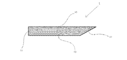
- FIG. 1 is a cross-sectional view illustrating an example of the glass plate of the present invention.
- the glass plate 1 has two main surfaces 10 (front surface and back surface) facing each other in the thickness direction, and a part of the end surface 11 is an inclined surface 12.
- the angle ⁇ between the main surface 10 and the inclined surface 12 is 35 °.
- the main surface 10 and the inclined surface 12 are directly connected, but in order to increase the strength of the glass plate 1, a chamfered surface (for example, a rounded chamfered surface) is provided between the main surface 10 and the inclined surface 12.
- FIG. 2 is a cross-sectional view for explaining an example of the glass plate 1 of the present invention. The difference from FIG.
- the inclined surface 12 is not formed over the entire plate thickness direction, but is partially formed. It is a point that has been formed. Also in FIG. 2, the angle ⁇ between the main surface 10 and the slope 12 is 35 °. In addition, similarly to FIG. 1, a chamfered surface may be provided between the end surface 11 and the inclined surface 12.
- FIG. 3 is a schematic cross-sectional view for explaining the direction in which light travels inside the glass plate.
- FIG. 3A shows a direction in which light travels inside the glass plate when light is directly applied to the inclined surface
- FIG. 3B shows a direction in which light is applied to the main surface on the opposite side to the inclined surface. It shows the direction in which light travels inside the glass plate when irradiated.
- the light changes its course on an inclined surface and propagates while causing total internal reflection inside the glass plate.
- the surface roughness Ra of the inclined surface is 1 ⁇ m or less. This makes it difficult for light to be scattered on the inclined surface. As a result, light can be easily propagated inside the glass plate.
- At least one main surface has a surface roughness Ra of 100 nm or less. This makes it easy for light to be totally reflected inside the glass plate.
- the glass plate of the present invention preferably contains 10 to 60% of SiO 2 , 1 to 40% of BaO, and 0.5 to 40% of TiO 2 + La 2 O 3 by mass%. This makes it easy to produce a glass plate having high devitrification resistance and high refractive index.
- TiO 2 + La 2 O 3 indicates the total amount of TiO 2 and La 2 O 3 .
- the glass plate of the present invention preferably has an uneven structure formed on one main surface. With this configuration, light guided inside the glass plate is easily emitted to the outside. As a result, the image of the head mounted display becomes clear.
- the glass plate of the present invention is preferably used for a light guide plate of a head mounted display.
- FIG. 2 is a schematic cross-sectional view illustrating an example of the glass plate of the present invention.
- FIG. 2 is a schematic cross-sectional view illustrating an example of the glass plate of the present invention.
- FIG. 4 is a schematic cross-sectional view for explaining a direction in which light travels inside a glass plate.
- the refractive index nd is 1.55 or more, preferably 1.58 or more, 1.60 or more, 1.63 or more, 1.65 or more, 1.68 or more, particularly 1.70 or more. It is. If the refractive index nd is too low, it becomes difficult for total reflection of light to occur inside the glass plate, and the degree of freedom in optical design tends to decrease. On the other hand, when the refractive index nd is too high, the glass skeleton tends to be unstable, and in that case, it is difficult to form the glass skeleton, so that the production efficiency of the glass plate tends to decrease. Therefore, the refractive index nd is 2.30 or less, preferably 2.00 or less, 1.90 or less, 1.85 or less, particularly 1.80 or less.
- the end surface has an inclined surface (preferably, all or a part of one end surface among the four end surfaces is an inclined surface), and the angle formed between the inclined surface and the main surface is It is 5 to 85 °, preferably 20 to 70 °, particularly 30 to 60 °.
- the angle between the inclined surface and the main surface is out of the above range, when light is irradiated from the main surface toward the inclined surface, it is difficult for the light to propagate inside the glass plate.
- the surface roughness Ra of the inclined surface is 1 ⁇ m or less, preferably 500 nm or less, 100 nm or less, 10 nm or less, 2 nm or less, particularly 1 nm or less. If the surface roughness Ra of the inclined surface is too large, light is easily scattered on the inclined surface. As a result, it becomes difficult for light to propagate inside the glass plate.
- ⁇ ⁇ Various methods can be adopted as a method of forming an inclined surface on a part of the end surface. For example, a method of forming an inclined surface by grinding and polishing, a method of forming an inclined surface by laser processing, and a method of forming an inclined surface by hot pressing can be adopted.
- the surface roughness Ra of at least one principal surface is preferably 100 nm or less, 10 nm or less, 2 nm or less, 1 nm, particularly 0.5 nm or less. If the surface roughness Ra of the main surface is too large, it is difficult for light to be totally reflected inside the glass plate.
- the glass plate preferably contains 10 to 60% of SiO 2 , 1 to 40% of BaO, and 0.5 to 40% of TiO 2 + La 2 O 3 by mass% as a glass composition.
- the reasons for defining the glass composition in this way are described below. In the description of the content range of each component,% means mass%.
- the content of SiO 2 is preferably from 10 to 60%.
- the content of SiO 2 is preferably at least 15%, at least 20%, at least 25%, at least 30%, particularly preferably at least 35%.
- the content of SiO 2 is preferably at most 55%, at most 51%, at most 48%, at most 45%, particularly preferably at most 42%.
- BaO is a component among alkaline earth metal oxides that raises the refractive index without extremely lowering the high-temperature viscosity.
- the content of BaO is preferably from 1 to 40%.
- the content of BaO is preferably at most 35%, at most 32%, at most 30%, particularly preferably at most 28%.
- the content of BaO is preferably 5% or more, 10% or more, 12% or more, 15% or more, 17% or more, 20% or more, and 23% or more, and particularly preferably 25% or more.
- TiO 2 and La 2 O 3 are components that effectively increase the refractive index. Therefore, the total amount of TiO 2 and La 2 O 3 is preferably 0.5% or more, 1% or more, 3% or more, 5% or more, 8% or more, 11% or more, 15% or more, and particularly preferably. Is 17% or more. On the other hand, when the total amount of TiO 2 and La 2 O 3 increases, the devitrification resistance tends to decrease. Therefore, the total amount of TiO 2 and La 2 O 3 is preferably at most 40%, at most 30%, at most 25%, particularly preferably at most 22%.
- TiO 2 is a component that maximizes the refractive index among general oxides except for heavy metal oxides such as rare earth oxides.
- the content of TiO 2 is preferably 0 to 35%, 0.1 to 30%, 0.1 to 15%, 1 to 12%, 2 to 11%, and 3 to 10%, and particularly preferably. 4 to 9%.
- the content of TiO 2 is preferably 7 to 35%, 15 to 32%, and particularly preferably 20 to 30%.
- La 2 O 3 is a component that effectively increases the refractive index.
- the content of La 2 O 3 is preferably 0 to 15%, 0 to 13%, 5 to 12%, and particularly preferably 7 to 11%.
- the content of Al 2 O 3 is preferably 0 to 8%.
- the content of Al 2 O 3 is preferably 8% or less, 7% or less, and particularly preferably 6% or less.
- the content of Al 2 O 3 is preferably at least 0.1%, at least 0.5%, at least 1%, at least 3%, particularly preferably at least 5%.
- the content of B 2 O 3 is preferably 0 to 15%.
- the content of B 2 O 3 is preferably 9% or less, 8% or less, and particularly preferably 7% or less.
- the content of B 2 O 3 is preferably 1% or more and 3% or more, and particularly preferably 5% or more.
- the content of MgO is preferably 0 to 12%.
- MgO is a component that increases the Young's modulus and reduces the high-temperature viscosity.
- the content of MgO is preferably 10% or less, 5% or less, 3% or less, 2% or less, 1.5% or less, 1% or less, and particularly preferably 0.5% or less.
- the content of CaO is preferably 0 to 15%.
- the content of CaO is preferably 13% or less, 10% or less, 8% or less, and particularly preferably 7% or less.
- the content of CaO is preferably at least 0.5%, at least 1%, at least 3%, at least 4%, particularly preferably at least 5%.
- the content of SrO is preferably 0 to 15%.
- the content of SrO is preferably 13% or less, 12% or less, and particularly preferably 11% or less.
- the content of SrO is preferably at least 1%, at least 3%, at least 5%, at least 7%, particularly preferably at least 10%.
- the content of ZnO is preferably 0 to 15%.
- the content of ZnO is preferably 15% or less, 12% or less, 10% or less, 8% or less, 6% or less, and particularly preferably 4% or less.
- the content of ZnO is preferably at least 0.1%, at least 0.5%, more than 1%, at least 1.5%, at least 2%, at least 2.5%, particularly preferably at least 3%. It is.
- ZrO 2 is a component that raises the refractive index, but when its content increases, the liquidus temperature tends to decrease. Therefore, the content of ZrO 2 is preferably 0 to 10%, 0.1 to 7%, and 0.5 to 6%, and particularly preferably 1 to 5.5%.
- Nb 2 O 5 is a component that increases the refractive index, but as the content increases, the raw material cost tends to increase. Therefore, the content of Nb 2 O 5 is preferably 0 to 30%, 1 to 25%, 5 to 23%, 10 to 22%, and particularly preferably 15 to 21%.
- Li 2 O, Na 2 O, and K 2 O are components that lower the high-temperature viscosity and are components that increase the coefficient of thermal expansion. However, when these components are introduced in a large amount, the high-temperature viscosity is excessively reduced. , It is difficult to ensure a high liquidus viscosity. Therefore, the total amount of Li 2 O, Na 2 O and K 2 O is preferably 15% or less, 10% or less, 5% or less, 2% or less, 1% or less, and particularly preferably 0.5% or less. Is 0.1% or less. The content of each of Li 2 O, Na 2 O, and K 2 O is preferably 10% or less, 8% or less, 5% or less, 2% or less, 1% or less, 0.5% or less, Especially preferably, it is 0.1% or less.
- the total amount of Li 2 O, Na 2 O and K 2 O is preferably 0.1 to 25%, 5 to 23%, and 10 to 20%. , Especially 12 to 18%.
- the content of Li 2 O is preferably 10% or less, 8% or less, 5% or less, 2% or less, 1% or less, 0.5% or less, and particularly preferably 0.1% or less.
- the content of Na 2 O is preferably 1 to 22%, 3 to 20%, 5 to 15%, and particularly preferably 8 to 12%.
- the content of K 2 O is preferably from 0.1 to 10%, from 1 to 9%, from 2 to 8%, particularly preferably from 3 to 7%.
- one or more selected from the group consisting of As 2 O 3 , Sb 2 O 3 , CeO 2 , SnO 2 , F, Cl and SO 3 can be added in the range of 0 to 1%. .
- As 2 O 3 , Sb 2 O 3 and F are preferably used as much as possible from an environmental point of view, and their contents are preferably less than 0.1%.
- the content of CeO 2 is preferably 0 to 1%, 0.01 to 0.5%, and particularly preferably 0.05 to 0.4%.
- the content of SnO 2 is preferably 0 to 1%, 0.01 to 0.5%, and particularly preferably 0.05 to 0.4%.
- the total amount of SnO 2 , SO 3 and Cl is preferably 0 to 1%, 0.001 to 1%, 0.01 to 0.5%, and particularly preferably 0.05 to 0.3%. It is.
- PbO is a component that reduces high-temperature viscosity, but it is preferable to minimize its use from an environmental point of view.
- the content of PbO is preferably 0.5% or less, particularly preferably less than 0.1%.
- Bi 2 O 3 , Gd 2 O 3 , Ta 2 O 5, and WO 3 are components that increase the refractive index, but are expensive and difficult to obtain in large quantities.
- the content of each of these components is preferably 1% or less, particularly preferably 0.5% or less.
- Fe 2 O 3 and Cr 2 O 3 are components that are mixed as raw material impurities, but when these components increase, the transmittance inside the glass plate tends to decrease. Therefore, the content of Fe 2 O 3 is preferably 500 ppm (0.05%) or less, 200 ppm or less, 100 ppm or less, 50 ppm or less, and particularly preferably 30 ppm or less.
- the content of Cr 2 O 3 is preferably 5 ppm (0.0005%) or less, 3 ppm or less, 2 ppm or less, 1 ppm or less, and particularly preferably 0.5 ppm or less. When a high-purity glass raw material is used, the contents of Fe 2 O 3 and Cr 2 O 3 can be reduced.
- the glass plate of the present invention preferably has the following characteristics.
- the density is preferably 5.0 g / cm 3 or less, 4.8 g / cm 3 or less, 4.5 g / cm 3 or less, 4.3 g / cm 3 or less, 3.7 g / cm 3 or less, particularly 3.5 g / cm 3 or less. cm 3 or less. In this way, the weight of the device can be reduced.
- the “density” can be measured by the well-known Archimedes method.
- the thermal expansion coefficient is preferably 30 ⁇ 10 ⁇ 7 to 100 ⁇ 10 ⁇ 7 / ° C., 40 ⁇ 10 ⁇ 7 to 90 ⁇ 10 ⁇ 7 / ° C., and 60 ⁇ 10 ⁇ 7 to 85 ⁇ 10 ⁇ 7 / ° C., particularly 65 ⁇ 10 ⁇ 7 to 80 ⁇ 10 ⁇ 7 / ° C.
- the “thermal expansion coefficient” is a value measured by a dilatometer and indicates an average value in a temperature range of 30 to 380 ° C.
- the strain point is preferably 500 ° C or higher, 550 ° C or higher, 600 ° C or higher, 620 ° C or higher, particularly 640 ° C or higher. If the strain point is too low, the glass plate tends to thermally shrink due to high-temperature heat treatment in the device manufacturing process.
- the “strain point” indicates a value measured based on the method of ASTM C336.
- the temperature in the high temperature viscosity 10 2.5 dPa ⁇ s preferably 1400 ° C. or less, 1300 ° C. or less, 1200 ° C. or less, in particular 1100 ° C. or less.
- the melting property is reduced, and the production efficiency of the glass sheet is reduced.
- the temperature in the high temperature viscosity of 10 2.5 dPa ⁇ s is refers to a value measured by a platinum ball pulling method.
- the liquidus temperature is preferably 1200 ° C or lower, 1150 ° C or lower, 1130 ° C or lower, 1100 ° C or lower, 1050 ° C or lower, 1030 ° C or lower, 1000 ° C or lower, 980 ° C or lower, particularly 950 ° C or lower.
- the liquidus viscosity is preferably 10 3.0 dPa ⁇ s or more, 10 3.5 dPa ⁇ s or more, 10 4.0 dPa ⁇ s or more, 10 4.5 dPa ⁇ s or more, 10 4.8 dPa ⁇ s or more, 10 5.0 dPa ⁇ s or more, 10 5.2 dPa ⁇ s or more, particularly 10 5.3 dPa ⁇ s or more.
- the glass is less likely to be devitrified at the time of molding, so that the glass plate can be easily formed by a float method, an overflow down draw method, or the like.
- liquidus viscosity refers to a value obtained by measuring the viscosity of glass at a liquidus temperature by a platinum ball pulling-up method.
- Liquid phase temperature means that the glass powder passing through a standard sieve 30 mesh (500 ⁇ m), remaining in the 50 mesh (300 ⁇ m) is placed in a platinum boat, and kept in a temperature gradient furnace for 24 hours to determine the temperature at which crystals precipitate. Refers to the measured value.
- the internal transmittance at an optical path length of 10 mm and a wavelength of 550 nm is preferably 80% or more, 85% or more, 90% or more, particularly 95% or more. If the internal transmittance is too low, the loss of light inside the glass plate increases.
- the plate thickness is preferably 3 mm or less, 2 mm or less, particularly preferably 1 mm or less, and is preferably 0.01 mm or more, 0.03 mm or more, particularly 0.05 mm or more. If the thickness of the glass plate is too large, the mass of the glass plate becomes large, so that it becomes difficult to apply the glass plate to a light guide plate or the like of a head mounted display. On the other hand, if the thickness of the glass plate is too small, handling becomes difficult when assembling the device.
- the glass plate of the present invention is preferably formed by an overflow down draw method, a slot down method, a redraw method, a float method, or a roll out method, and particularly preferably formed by an overflow down draw method. By doing so, the surface smoothness of the main surface of the glass plate can be improved.
- ⁇ It is preferable to laminate a plurality of the glass plates of the present invention to form a laminate. By doing so, it is possible to project different images in the depth direction of the display image, and it is easy to realize 3D display.
- As a lamination method it is preferable to laminate glass plates corresponding to each of red display, green display, and blue display.
- the number of laminations is, for example, 3 or more, 5 or more, especially 10 or more.
- the glass plate of the present invention preferably has an uneven structure formed on one main surface. This makes it easier for light that has propagated inside the glass plate to exit to the outside. As a result, the image of the head mounted display becomes clear.
- the concavo-convex structure for example, a structure in which a periodic structure is formed and light is extracted outside by a diffraction phenomenon is preferable.
- a method of forming the uneven structure for example, a method such as a photolithography method, a sputtering method using a mask, a method of locally etching using a laser after forming a uniform film, and an imprint method using a mold is adopted. can do.
- Table 1 shows sample No. 1 to 10 are shown.
- NA in a table means unmeasured.
- Each sample in the table was prepared as follows. First, a glass raw material was prepared so as to have the glass composition shown in the table, and was melted at 1400 ° C. for 24 hours using a platinum pot. Next, the obtained molten glass was poured onto a carbon plate and formed into a flat plate shape. The properties in the table were evaluated for the obtained glass plate.
- Density is a value measured by the well-known Archimedes method.
- the coefficient of thermal expansion ⁇ is a value measured by a dilatometer and is an average value in a temperature range of 30 to 380 ° C.
- the strain point and the annealing point are values measured based on the method of ASTM C336.
- the softening point is a value measured based on the method of ASTM C338.
- Temperature at the high temperature viscosity 10 4.0 dPa ⁇ s, 10 3.0 dPa ⁇ s, 10 2.5 dPa ⁇ s and 10 2.0 dPa ⁇ s is a value measured by a platinum ball pulling method.
- the liquidus temperature was measured by passing through a standard sieve 30 mesh (500 ⁇ m), placing the glass powder remaining on the 50 mesh (300 ⁇ m) in a platinum boat, and holding it in a temperature gradient furnace for 24 hours to measure the temperature at which crystals precipitated. Value.
- the liquidus viscosity is a value obtained by measuring the viscosity of glass at a liquidus temperature by a platinum ball pulling-up method.
- a glass raw material is prepared so as to have a glass composition of 1, and the obtained glass batch is melted in a continuous melting furnace, and then formed into a plate having a thickness of 1 mm by an overflow down draw method, and a surface roughness Ra of a main surface is obtained.
- Ra 0.2 nm.
- an inclined surface is formed over the entire plate thickness direction using a grindstone, the angle between the inclined surface and the main surface is 60 °, and the surface roughness of the inclined surface is large. It processed so that Ra might be set to 0.2 nm.
- a periodic concavo-convex structure made of SiO 2 was formed on one main surface of the glass plate by photolithography, and a gap between the concavo-convex structures was filled with a resin. Seven obtained glass plates were laminated to obtain a laminate. Further, the sample Nos. With respect to 1, a laminate was obtained in the same manner.
- sample No. The glass raw material was prepared so as to have a glass composition of 2, and the obtained glass batch was melted in a continuous melting furnace, and then formed into a 0.5 mm-thick plate by an overflow downdraw method, and the surface roughness of the main surface was adjusted. Glass plates each having a thickness Ra of 0.2 nm were obtained. For a part of the end surface of the obtained glass plate, a laser light is used to form an inclined surface over the entire plate thickness direction, and the angle between the inclined surface and the main surface is 30 °, and the surface of the inclined surface is formed. It processed so that roughness Ra might be set to 0.5 nm.
- a periodic concavo-convex structure made of SiO 2 was formed on one main surface of the glass plate by a sputtering method using a mask, and a gap between the concavo-convex structures was filled with a resin.
- Ten obtained glass plates were laminated to obtain a laminate. Further, the sample Nos. Regarding No. 3, a laminate was obtained in the same manner.
- the laminate obtained in this way when irradiating light perpendicular to the main surface to the inclined surface or the main surface opposite to the inclined surface of each glass plate, the incident light is reflected inside each glass plate. Can be propagated to Therefore, it can be suitably used as a light guide plate of a head mounted display.
Landscapes
- Chemical & Material Sciences (AREA)
- Physics & Mathematics (AREA)
- Materials Engineering (AREA)
- Chemical Kinetics & Catalysis (AREA)
- General Chemical & Material Sciences (AREA)
- Geochemistry & Mineralogy (AREA)
- Life Sciences & Earth Sciences (AREA)
- Organic Chemistry (AREA)
- Engineering & Computer Science (AREA)
- General Physics & Mathematics (AREA)
- Optics & Photonics (AREA)
- Glass Compositions (AREA)
- Surface Treatment Of Glass (AREA)
Abstract
Ce verre en plaque est caractérisé en ce qu'il a un indice de réfraction nd qui se situe dans la plage de 1,55 à 2,30, inclus; avec une surface inclinée dans au moins une partie de la face d'extrémité; l'angle formé par ladite surface inclinée et la surface principale se situant dans la plage de 5° à 85°, inclus; et la rugosité de surface Ra de la surface inclinée ne dépassant pas 1 µm.
Priority Applications (4)
| Application Number | Priority Date | Filing Date | Title |
|---|---|---|---|
| JP2020527425A JP7389409B2 (ja) | 2018-06-26 | 2019-06-18 | ガラス板 |
| US15/734,354 US11629089B2 (en) | 2018-06-26 | 2019-06-18 | Plate glass |
| CN201980040739.6A CN112292359A (zh) | 2018-06-26 | 2019-06-18 | 玻璃板 |
| JP2023147531A JP2023175779A (ja) | 2018-06-26 | 2023-09-12 | ガラス板 |
Applications Claiming Priority (2)
| Application Number | Priority Date | Filing Date | Title |
|---|---|---|---|
| JP2018120480 | 2018-06-26 | ||
| JP2018-120480 | 2018-06-26 |
Publications (1)
| Publication Number | Publication Date |
|---|---|
| WO2020004140A1 true WO2020004140A1 (fr) | 2020-01-02 |
Family
ID=68986533
Family Applications (1)
| Application Number | Title | Priority Date | Filing Date |
|---|---|---|---|
| PCT/JP2019/024077 Ceased WO2020004140A1 (fr) | 2018-06-26 | 2019-06-18 | Verre en plaque |
Country Status (4)
| Country | Link |
|---|---|
| US (1) | US11629089B2 (fr) |
| JP (2) | JP7389409B2 (fr) |
| CN (1) | CN112292359A (fr) |
| WO (1) | WO2020004140A1 (fr) |
Cited By (1)
| Publication number | Priority date | Publication date | Assignee | Title |
|---|---|---|---|---|
| WO2023017759A1 (fr) * | 2021-08-12 | 2023-02-16 | 日本電気硝子株式会社 | Plaque de verre optique |
Families Citing this family (2)
| Publication number | Priority date | Publication date | Assignee | Title |
|---|---|---|---|---|
| US11481239B2 (en) | 2016-12-07 | 2022-10-25 | Vmware, Inc. | Apparatus and methods to incorporate external system to approve deployment provisioning |
| US12070415B1 (en) | 2023-12-11 | 2024-08-27 | John Z. Blazevich | Eye drop dispenser |
Citations (2)
| Publication number | Priority date | Publication date | Assignee | Title |
|---|---|---|---|---|
| JP2013061593A (ja) * | 2011-09-15 | 2013-04-04 | Seiko Epson Corp | 虚像表示装置及び虚像表示装置の製造方法 |
| WO2017018375A1 (fr) * | 2015-07-30 | 2017-02-02 | 日本電気硝子株式会社 | Panneau de guidage de lumière, et panneau de guidage de lumière stratifié utilisant ce panneau de guidage de lumière |
Family Cites Families (12)
| Publication number | Priority date | Publication date | Assignee | Title |
|---|---|---|---|---|
| KR101276587B1 (ko) * | 2009-07-08 | 2013-06-19 | 니폰 덴키 가라스 가부시키가이샤 | 유리판 |
| US9428417B2 (en) * | 2011-07-13 | 2016-08-30 | Nippon Electric Glass Co., Ltd. | Composite substrate |
| JP6065631B2 (ja) | 2013-02-13 | 2017-01-25 | セイコーエプソン株式会社 | 虚像表示装置 |
| KR102225279B1 (ko) * | 2014-03-14 | 2021-03-09 | 니폰 덴키 가라스 가부시키가이샤 | 디스플레이의 커버 부재 및 그 제조 방법 |
| KR102282394B1 (ko) | 2015-01-26 | 2021-07-26 | 매직 립, 인코포레이티드 | 개선된 회절 그레이팅 구조들을 갖는 가상 및 증강 현실 시스템들 및 방법들 |
| WO2016132985A1 (fr) * | 2015-02-18 | 2016-08-25 | コニカミノルタ株式会社 | Élément optique et procédé permettant de fabriquer un élément de formation d'image |
| CN206736103U (zh) * | 2015-06-09 | 2017-12-12 | 旭硝子株式会社 | 玻璃导光板 |
| JP6687885B2 (ja) | 2016-01-05 | 2020-04-28 | 株式会社リコー | 虚像光学系及び虚像表示装置 |
| JP2017161564A (ja) | 2016-03-07 | 2017-09-14 | セイコーエプソン株式会社 | 導光装置及び虚像表示装置 |
| CN107290816B (zh) | 2016-03-30 | 2020-04-24 | 中强光电股份有限公司 | 光波导元件以及具有此光波导元件的头戴式显示装置 |
| US10815145B2 (en) | 2016-03-31 | 2020-10-27 | Corning Incorporated | High index glass and devices incorporating such |
| CN106324847B (zh) | 2016-10-21 | 2018-01-23 | 京东方科技集团股份有限公司 | 一种三维显示装置 |
-
2019
- 2019-06-18 CN CN201980040739.6A patent/CN112292359A/zh active Pending
- 2019-06-18 JP JP2020527425A patent/JP7389409B2/ja active Active
- 2019-06-18 WO PCT/JP2019/024077 patent/WO2020004140A1/fr not_active Ceased
- 2019-06-18 US US15/734,354 patent/US11629089B2/en active Active
-
2023
- 2023-09-12 JP JP2023147531A patent/JP2023175779A/ja active Pending
Patent Citations (2)
| Publication number | Priority date | Publication date | Assignee | Title |
|---|---|---|---|---|
| JP2013061593A (ja) * | 2011-09-15 | 2013-04-04 | Seiko Epson Corp | 虚像表示装置及び虚像表示装置の製造方法 |
| WO2017018375A1 (fr) * | 2015-07-30 | 2017-02-02 | 日本電気硝子株式会社 | Panneau de guidage de lumière, et panneau de guidage de lumière stratifié utilisant ce panneau de guidage de lumière |
Cited By (1)
| Publication number | Priority date | Publication date | Assignee | Title |
|---|---|---|---|---|
| WO2023017759A1 (fr) * | 2021-08-12 | 2023-02-16 | 日本電気硝子株式会社 | Plaque de verre optique |
Also Published As
| Publication number | Publication date |
|---|---|
| CN112292359A (zh) | 2021-01-29 |
| US11629089B2 (en) | 2023-04-18 |
| US20210221728A1 (en) | 2021-07-22 |
| JP7389409B2 (ja) | 2023-11-30 |
| JP2023175779A (ja) | 2023-12-12 |
| JPWO2020004140A1 (ja) | 2021-08-02 |
Similar Documents
| Publication | Publication Date | Title |
|---|---|---|
| JP7772130B2 (ja) | 導光板用ガラス板 | |
| EP3330754B1 (fr) | Panneau de guidage de lumière, et panneau de guidage de lumière stratifié utilisant ce panneau de guidage de lumière | |
| JP7222360B2 (ja) | 反射防止膜付ガラス基板及び光学部品 | |
| JP7392914B2 (ja) | ガラス | |
| JP2023175779A (ja) | ガラス板 | |
| JP7602188B2 (ja) | 結晶化ガラス | |
| WO2012008236A1 (fr) | Plaque de verre | |
| US20200325063A1 (en) | Optical glass and optical member | |
| US20240182351A1 (en) | Plate glass | |
| JP7648989B2 (ja) | ガラス板 | |
| CN116715435A (zh) | 光学玻璃、光学元件坯料及光学元件 | |
| JP7228135B2 (ja) | ガラス基板積層体の製造方法、ガラス基板、ガラス基板積層体及びヘッドマウントディスプレイ | |
| JP2021001104A (ja) | ガラス | |
| WO2023171519A1 (fr) | Verre | |
| TW202337857A (zh) | 光學玻璃、光學元件坯料及光學元件 | |
| JP2023181103A (ja) | ガラス |
Legal Events
| Date | Code | Title | Description |
|---|---|---|---|
| 121 | Ep: the epo has been informed by wipo that ep was designated in this application |
Ref document number: 19825382 Country of ref document: EP Kind code of ref document: A1 |
|
| ENP | Entry into the national phase |
Ref document number: 2020527425 Country of ref document: JP Kind code of ref document: A |
|
| NENP | Non-entry into the national phase |
Ref country code: DE |
|
| 122 | Ep: pct application non-entry in european phase |
Ref document number: 19825382 Country of ref document: EP Kind code of ref document: A1 |