WO2020004221A1 - Refrigeration cycle apparatus - Google Patents
Refrigeration cycle apparatus Download PDFInfo
- Publication number
- WO2020004221A1 WO2020004221A1 PCT/JP2019/024496 JP2019024496W WO2020004221A1 WO 2020004221 A1 WO2020004221 A1 WO 2020004221A1 JP 2019024496 W JP2019024496 W JP 2019024496W WO 2020004221 A1 WO2020004221 A1 WO 2020004221A1
- Authority
- WO
- WIPO (PCT)
- Prior art keywords
- evaporator
- refrigerant
- upstream
- downstream
- heat exchanger
- Prior art date
- Legal status (The legal status is an assumption and is not a legal conclusion. Google has not performed a legal analysis and makes no representation as to the accuracy of the status listed.)
- Ceased
Links
Images



Classifications
-
- F—MECHANICAL ENGINEERING; LIGHTING; HEATING; WEAPONS; BLASTING
- F25—REFRIGERATION OR COOLING; COMBINED HEATING AND REFRIGERATION SYSTEMS; HEAT PUMP SYSTEMS; MANUFACTURE OR STORAGE OF ICE; LIQUEFACTION SOLIDIFICATION OF GASES
- F25B—REFRIGERATION MACHINES, PLANTS OR SYSTEMS; COMBINED HEATING AND REFRIGERATION SYSTEMS; HEAT PUMP SYSTEMS
- F25B1/00—Compression machines, plants or systems with non-reversible cycle
-
- F—MECHANICAL ENGINEERING; LIGHTING; HEATING; WEAPONS; BLASTING
- F25—REFRIGERATION OR COOLING; COMBINED HEATING AND REFRIGERATION SYSTEMS; HEAT PUMP SYSTEMS; MANUFACTURE OR STORAGE OF ICE; LIQUEFACTION SOLIDIFICATION OF GASES
- F25B—REFRIGERATION MACHINES, PLANTS OR SYSTEMS; COMBINED HEATING AND REFRIGERATION SYSTEMS; HEAT PUMP SYSTEMS
- F25B39/00—Evaporators; Condensers
- F25B39/02—Evaporators
-
- F—MECHANICAL ENGINEERING; LIGHTING; HEATING; WEAPONS; BLASTING
- F25—REFRIGERATION OR COOLING; COMBINED HEATING AND REFRIGERATION SYSTEMS; HEAT PUMP SYSTEMS; MANUFACTURE OR STORAGE OF ICE; LIQUEFACTION SOLIDIFICATION OF GASES
- F25B—REFRIGERATION MACHINES, PLANTS OR SYSTEMS; COMBINED HEATING AND REFRIGERATION SYSTEMS; HEAT PUMP SYSTEMS
- F25B5/00—Compression machines, plants or systems, with several evaporator circuits, e.g. for varying refrigerating capacity
-
- F—MECHANICAL ENGINEERING; LIGHTING; HEATING; WEAPONS; BLASTING
- F25—REFRIGERATION OR COOLING; COMBINED HEATING AND REFRIGERATION SYSTEMS; HEAT PUMP SYSTEMS; MANUFACTURE OR STORAGE OF ICE; LIQUEFACTION SOLIDIFICATION OF GASES
- F25B—REFRIGERATION MACHINES, PLANTS OR SYSTEMS; COMBINED HEATING AND REFRIGERATION SYSTEMS; HEAT PUMP SYSTEMS
- F25B5/00—Compression machines, plants or systems, with several evaporator circuits, e.g. for varying refrigerating capacity
- F25B5/04—Compression machines, plants or systems, with several evaporator circuits, e.g. for varying refrigerating capacity arranged in series
-
- F—MECHANICAL ENGINEERING; LIGHTING; HEATING; WEAPONS; BLASTING
- F28—HEAT EXCHANGE IN GENERAL
- F28D—HEAT-EXCHANGE APPARATUS, NOT PROVIDED FOR IN ANOTHER SUBCLASS, IN WHICH THE HEAT-EXCHANGE MEDIA DO NOT COME INTO DIRECT CONTACT
- F28D7/00—Heat-exchange apparatus having stationary tubular conduit assemblies for both heat-exchange media, the media being in contact with different sides of a conduit wall
- F28D7/10—Heat-exchange apparatus having stationary tubular conduit assemblies for both heat-exchange media, the media being in contact with different sides of a conduit wall the conduits being arranged one within the other, e.g. concentrically
-
- F—MECHANICAL ENGINEERING; LIGHTING; HEATING; WEAPONS; BLASTING
- F28—HEAT EXCHANGE IN GENERAL
- F28F—DETAILS OF HEAT-EXCHANGE AND HEAT-TRANSFER APPARATUS, OF GENERAL APPLICATION
- F28F9/00—Casings; Header boxes; Auxiliary supports for elements; Auxiliary members within casings
-
- F—MECHANICAL ENGINEERING; LIGHTING; HEATING; WEAPONS; BLASTING
- F28—HEAT EXCHANGE IN GENERAL
- F28F—DETAILS OF HEAT-EXCHANGE AND HEAT-TRANSFER APPARATUS, OF GENERAL APPLICATION
- F28F9/00—Casings; Header boxes; Auxiliary supports for elements; Auxiliary members within casings
- F28F9/26—Arrangements for connecting different sections of heat-exchange elements, e.g. of radiators
Definitions
- the disclosure in this specification relates to a refrigeration cycle device.
- the refrigerant used for the refrigeration cycle is required to have good refrigerant characteristics such as environmental load and cooling capacity.
- a refrigerant using a mixed refrigerant obtained by mixing different types of refrigerants instead of using a single refrigerant is known.
- the mixed refrigerant obtained by mixing the high-boiling refrigerant and the low-boiling refrigerant evaporates in the evaporator, and the high-boiling refrigerant becomes a non-azeotropic mixed refrigerant that evaporates later. There are cases.
- Patent Document 1 In order to reduce the bias of the temperature distribution, in Patent Document 1, in a heat exchanger for a non-azeotropic mixed refrigerant, a constricted portion having a reduced flow path cross-sectional area is provided at an intermediate portion of a pipe of the heat exchanger. . With this configuration, the temperature of the refrigerant that rises toward the outlet side when there is no constricted portion is made substantially uniform or decreases toward the outlet side by the constricted portion, thereby reducing the temperature distribution bias.
- One object of the disclosure is to provide a refrigeration cycle apparatus in which a non-azeotropic mixed refrigerant uses a refrigeration cycle in which the unevenness of the temperature distribution in the entire evaporator is reduced.
- the refrigeration cycle apparatus disclosed herein is a refrigeration cycle apparatus that includes a compressor, a condenser, a decompression device, an evaporator, and an internal heat exchanger, and performs cooling by circulating a non-azeotropic mixed refrigerant.
- the evaporator is provided with an upstream heat exchange section that exchanges heat between the non-azeotropic mixed refrigerant flowing inside and the external fluid flowing outside, and is provided downstream of the upstream heat exchange section in the flow of the non-azeotropic mixed refrigerant.
- a heat exchange unit having a non-azeotropic mixed refrigerant flowing inside and a downstream heat exchange unit for exchanging heat with an external fluid flowing outside, and the internal heat exchanger is upstream after flowing out of the pressure reducing device.
- the refrigerant whose temperature has risen by flowing through the upstream heat exchange section and the refrigerant before flowing into the upstream heat exchange section are mixed using the internal heat exchanger. Can be heat exchanged.
- the temperature in the downstream heat exchange section is reduced as compared with the case where the internal heat exchanger is not provided, and the upstream heat
- the temperature of the exchange section and the temperature of the downstream heat exchange section can be made close to each other. Therefore, in the refrigeration cycle using the non-azeotropic mixed refrigerant, it is possible to provide a refrigeration cycle apparatus in which the deviation of the temperature distribution in the entire evaporator is reduced.
- FIG. 5 is a configuration diagram illustrating a flow of a refrigerant in a cross section of the internal heat exchanger along a line VV in FIG. 4. It is a perspective view showing the evaporator of a 3rd embodiment. It is an exploded view showing a flow of a refrigerant in an evaporator of a 3rd embodiment. It is a perspective view showing an internal heat exchanger of a 4th embodiment. It is an exploded view showing a flow of a refrigerant in an internal heat exchanger of a 4th embodiment.
- the refrigeration cycle device 1 is a device that generates cold or warm heat using a refrigerant.
- the refrigeration cycle device 1 is used, for example, as a part of a vehicle air-conditioning system that is mounted on a vehicle and cools or heats a vehicle compartment.
- the refrigeration cycle device 1 can be widely applied to devices such as a home air conditioner and a server cooling device other than the vehicle air conditioning system.
- the refrigeration cycle apparatus 1 includes a compressor 2, a condenser 3, a decompression device 4, an evaporator 30, and an internal heat exchanger 50.
- the refrigeration cycle apparatus 1 includes a refrigerant flow path 20 that connects the components and provides a flow path through which the non-azeotropic mixed refrigerant circulates.
- a non-azeotropic mixed refrigerant is used as the refrigerant.
- the non-azeotropic mixed refrigerant is a mixture of refrigerants having different boiling points, and is a refrigerant whose composition changes due to a change in the gas-liquid ratio of each refrigerant due to heat exchange.
- the boiling point of the non-azeotropic mixed refrigerant changes due to the composition change.
- the refrigerant having the lower boiling point evaporates first, whereby the composition of the non-azeotropic mixed refrigerant changes, and the boiling point of the refrigerant as a whole gradually increases during the evaporation process.
- the boiling point is lowest on the inlet side of the heat exchanger where the refrigerant evaporates, and is highest on the outlet side. Therefore, in the heat exchanger in which the refrigerant is appropriately evaporated, a temperature gradient tends to be generated such that the temperature on the inlet side of the heat exchanger is the lowest and the temperature gradually increases toward the outlet side.
- the compressor 2 is a device that compresses a gaseous refrigerant into a state of high temperature and high pressure.
- the condenser 3 is a device that condenses the gaseous refrigerant compressed by the compressor 2 into a liquid.
- the condenser 3 functions as a heat exchanger that radiates heat of the refrigerant to the surroundings in the process of condensing the refrigerant and heats the periphery of the condenser 3.
- the decompression device 4 is a device that lowers the pressure of the refrigerant to facilitate evaporation from liquid to gas.
- the evaporator 30 is a device for evaporating the liquid refrigerant decompressed by the decompression device 4 into a gas.
- the evaporator 30 is a heat exchanger that cools the periphery of the evaporator 30 by removing heat from the surrounding external fluid in the process of evaporating the refrigerant.
- the external fluid is, for example, air.
- the internal heat exchanger 50 is a device that exchanges heat between the refrigerants flowing through the refrigeration cycle device 1.
- the evaporator 30 is configured by arranging two heat exchangers, an upstream evaporator 31 and a downstream evaporator 41, side by side.
- Each of the upstream evaporator 31 and the downstream evaporator 41 is a multi-flow type heat exchanger including a plurality of pipes in which refrigerant flows.
- the upstream evaporator 31 is located upstream of the downstream evaporator 41 in the flow of the refrigerant sent from the compressor 2.
- the upstream evaporator 31 includes an upper tank part 32 and a lower tank part 33.
- the upper tank part 32 and the lower tank part 33 face each other.
- the inside of the upper tank section 32 is partitioned into two independent areas of a first upper tank section 32a and a second upper tank section 32b.
- An upstream core section 35 is provided between the upper tank section 32 and the lower tank section 33.
- the upstream core portion 35 includes a plurality of flat tubes having a plurality of paths formed therein, and corrugated fins provided between the flat tubes.
- the upstream core portion 35 is divided into two regions, a first core portion 35a and a second core portion 35b.
- the first core portion 35a is provided between the first upper tank portion 32a and the lower tank portion 33.
- the second core 35b is provided between the second upper tank 32b and the lower tank 33.
- the upstream core section 35 provides an upstream heat exchange section of the evaporator 30.
- the downstream evaporator 41 includes an upper tank part 42 and a lower tank part 43.
- the upper tank part 42 and the lower tank part 43 face each other.
- the inside of the upper tank section 42 is partitioned into two independent areas, a first upper tank section 42a and a second upper tank section 42b.
- a downstream outlet pipe 49 is connected to the second upper tank portion 42b, and functions as an outlet for allowing the refrigerant to flow out of the evaporator 30.
- a downstream core part 45 is provided between the upper tank part 42 and the lower tank part 43.
- the downstream core portion 45 includes a plurality of flat tubes having a plurality of paths formed therein, and corrugated fins provided between the flat tubes.
- the downstream core portion 45 is divided into two regions, a first core portion 45a and a second core portion 45b.
- the first core portion 45a is provided between the first upper tank portion 42a and the lower tank portion 43.
- the second core portion 45b is provided between the second upper tank portion 42b and the lower tank portion 43.
- the downstream core part 45 provides a downstream heat exchange part of the evaporator 30.
- the internal heat exchanger 50 is a double-pipe heat exchanger including an inner pipe 51 and an outer pipe 55 provided outside the inner pipe 51.
- the internal heat exchanger 50 includes an upstream inlet pipe 52 that communicates the inner pipe 51 with the first upper tank 32a of the upstream evaporator 31.
- the internal heat exchanger 50 includes an upstream outlet pipe 53 that communicates the outer pipe 55 with the second upper tank portion 32b of the upstream evaporator 31.
- the internal heat exchanger 50 includes a downstream inlet pipe 56 that communicates the outer pipe 55 with the first upper tank portion 42a of the downstream evaporator 41.
- the internal heat exchanger 50 is located above the evaporator 30 so as to straddle the upper tank 32 of the upstream evaporator 31 and the upper tank 42 of the downstream evaporator 41. In other words, the internal heat exchanger 50 is integrally provided irremovably from the evaporator 30.
- the upstream core section 35 of the upstream evaporator 31 and the downstream core section 45 of the downstream evaporator 41 provide a core section 135 of the evaporator 30.
- the evaporator 30 performs heat exchange between the air and the refrigerant in the core section 135.
- the upstream core portion 35 of the upstream evaporator 31 is located more leeward of the air flow shown in the arrow F1 direction than the downstream core portion 45 of the downstream evaporator 41. Therefore, in the evaporator 30, the air is further cooled in the upstream core section 35 after being cooled in the downstream core section 45.
- the core part 135 provides a heat exchange part of the evaporator 30.
- the air provides an external fluid flowing outside the evaporator 30.
- the external fluid is not limited to gaseous air, but may be liquid water or the like.
- the flow of the refrigerant in the evaporator 30 for each of the three parts of the evaporator 30, the upstream evaporator 31, the internal heat exchanger 50, and the downstream evaporator 41, is shown below.
- the arrows indicated by solid lines indicate the flow of the refrigerant before flowing out of the upstream evaporator 31.
- the arrows indicated by the two-dot chain lines indicate the flow of the refrigerant after flowing out of the upstream evaporator 31.
- the refrigerant whose pressure has been reduced by the pressure reducing device 4 and whose temperature has decreased passes through the inner pipe 51 and flows into the upstream evaporator 31 from the upstream inlet pipe 52. At this time, the refrigerant exchanges heat with the refrigerant flowing through the outer tube 55 while passing through the inner tube 51.
- the flow of the refrigerant in the upstream evaporator 31 will be described below.
- the refrigerant spreads inside the first upper tank part 32a and flows down the first core part 35a from above.
- the refrigerant flows into the lower tank portion 33 communicating with the first core portion 35a, and spreads inside the lower tank portion 33.
- the refrigerant flows out of the lower tank portion 33, flows upward from the bottom through the second core portion 35b, and flows into the second upper tank portion 32b.
- the refrigerant that has flowed into the second upper tank portion 32b passes through the upstream outlet pipe 53 and flows out of the upstream evaporator 31.
- the refrigerant exchanges heat with external air in the process of flowing through the first core portion 35a and the second core portion 35b.
- the refrigerant having a low boiling point among the refrigerants forming the non-azeotropic mixed refrigerant evaporates more actively than the refrigerant having a high boiling point.
- the composition of the refrigerant changes due to this evaporation, and the refrigerant after flowing out of the second core portion 35b has a higher boiling point than the refrigerant before flowing into the first core portion 35a.
- the flow of the refrigerant in the internal heat exchanger 50 will be described below.
- the refrigerant flowing out of the upstream evaporator 31 flows from the upstream outlet pipe 53 into the outer pipe 55.
- the refrigerant moves in a state of being in contact with the outer surface of the inner tube 51 by flowing through the outer tube 55.
- the refrigerant and the refrigerant flowing through the inner tube 51 exchange heat, and flow out of the internal heat exchanger 50 through the downstream inlet tube 56.
- the refrigerant flows in a gas-liquid two-phase state.
- the refrigerant flowing through the inner tube 51 is in a gas-liquid two-phase state in which the ratio of the liquid phase is large
- the refrigerant flowing through the outer tube 55 is in a gas-liquid two-phase state in which the ratio of the gas phase is large.
- the refrigerant flowing through the inner pipe 51 and the refrigerant flowing through the outer pipe 55 exchange heat. That is, the low-temperature refrigerant flowing through the inner pipe 51 is heated by the high-temperature refrigerant flowing through the outer pipe 55, and the temperature rises.
- the high-temperature refrigerant flowing through the outer pipe 55 is cooled by the low-temperature refrigerant flowing through the inner pipe 51, and its temperature is reduced.
- the temperature of the refrigerant flowing into the upstream evaporator 31 and the temperature of the refrigerant flowing into the downstream evaporator 41 become substantially equal.
- the heat exchange using the internal heat exchanger 50 eliminates the temperature gradient of the refrigerant.
- the temperature difference between the refrigerant flowing into the upstream evaporator 31 and the refrigerant flowing into the downstream evaporator 41 may be reduced by the internal heat exchanger 50, and the temperature gradient of the refrigerant does not need to be completely eliminated. .
- the flow of the refrigerant in the downstream evaporator 41 will be described below.
- the refrigerant spreads inside the first upper tank portion 42a and flows down the first core portion 45a from above.
- the refrigerant flows into the lower tank portion 43 communicating with the first core portion 45a, and spreads inside the lower tank portion 43.
- the refrigerant flows out of the lower tank portion 43, flows upward from below through the second core portion 45b, and flows into the second upper tank portion 42b.
- the refrigerant flowing into the second upper tank portion 42b flows out of the downstream evaporator 41 through the downstream outlet pipe 49.
- the refrigerant exchanges heat with external air in the process of flowing through the first core portion 45a and the second core portion 45b.
- the refrigerants forming the non-azeotropic mixed refrigerant not only the refrigerant having a small boiling point and a low boiling point but also the refrigerant having a high boiling point which has not been evaporated very much in the upstream evaporator 31 is actively evaporated.
- the proportion of the refrigerant having a high boiling point in the liquid phase in the entire refrigerant increases.
- the refrigerant flowing into the upstream evaporator 31 and the refrigerant flowing into the downstream evaporator 41 exchange heat using the internal heat exchanger 50.
- the internal heat exchanger 50 when used, the temperature gradient generated by the characteristics of the non-azeotropic mixed refrigerant is eliminated by heat exchange between the refrigerants, and the temperature of the refrigerant flowing into the downstream evaporator 41 is increased by the upstream evaporation.
- the temperature is substantially equal to the temperature of the refrigerant flowing into the vessel 31.
- the temperature gradient generated due to the characteristics of the non-azeotropic mixed refrigerant is not eliminated, and the temperature of the refrigerant flowing into the downstream evaporator 41 is reduced by the refrigerant flowing into the upstream evaporator 31.
- the temperature becomes higher than the temperature. Therefore, the temperature distribution between the upstream evaporator 31 and the downstream evaporator 41 can be made substantially the same by using the internal heat exchanger 50, and the entire evaporator 30 can be compared with the case where the internal heat exchanger 50 is not used. The resulting bias in the temperature distribution can be reduced.
- the cooling performance of the evaporator 30 will be reduced. Assuming that the lowest refrigerant temperature at which frost formation does not occur in the evaporator 30 is 0 ° C., the state in which the refrigerant temperature on the inlet side where the temperature is most likely to decrease in the evaporator 30 is 0 ° C. This is the state with the highest cooling performance.
- the temperature of the refrigerant on the outlet side is 5 ° C.
- the average temperature of the evaporator 30 is 2.5 ° C.
- the temperature of the refrigerant on the outlet side is 10 ° C., so that the average temperature of the evaporator 30 is 5 ° C. Therefore, as the temperature gradient in the entire evaporator 30 is smaller, the average temperature in the evaporator 30 can be reduced, and the cooling performance of the evaporator 30 can be improved. That is, by reducing the temperature gradient in the entire evaporator 30 using the internal heat exchanger 50, frost formation in the evaporator 30 can be prevented and the cooling performance of the evaporator 30 can be improved.
- the internal heat exchanger 50 that exchanges heat between non-azeotropic mixed refrigerants is provided.
- the internal heat exchanger 50 flows out of the pressure reducing device 4 until it flows into the upstream core 35 of the upstream evaporator 31 and flows out of the upstream core 35 of the upstream evaporator 31.
- the refrigerant is extracted in the course of flowing through the core portion 135, exchanges heat with the refrigerant before flowing into the core portion 135, and then returns to the core portion 135 again.
- the refrigerant whose temperature has risen by flowing through a part of the evaporator 30 is cooled by the low-temperature refrigerant before flowing into the evaporator 30, and the cooled and lowered refrigerant is returned to the evaporator 30 again.
- the temperature gradient of the refrigerant in the entire evaporator 30 can be reduced, it is easy to exhibit high cooling performance in a state where frost formation on the evaporator 30 is prevented.
- the disadvantage of using the non-azeotropic mixed refrigerant as the refrigerant is reduced, and the optimal refrigerant is selected from various refrigerants including the non-azeotropic mixed refrigerant according to the application, and the refrigerant is used for the refrigeration cycle apparatus 1. Can be used.
- the internal heat exchanger 50 is provided integrally with the evaporator 30. For this reason, the piping through which the evaporator 30 and the internal heat exchanger 50 communicate and the refrigerant flows can be shortened. Therefore, the refrigeration cycle apparatus 1 is easily reduced in size.
- the internal heat exchanger 50 is provided in the upper tank 32 of the upstream evaporator 31 and the upper tank 42 of the downstream evaporator 41. Therefore, the inlet and outlet of the refrigerant in the evaporator 30 and the internal heat exchanger 50 can be adjacent to each other. Therefore, the piping through which the evaporator 30 communicates with the internal heat exchanger 50 and in which the refrigerant flows is shortened, and the refrigeration cycle apparatus 1 is easily reduced in size.
- the internal heat exchanger 50 is provided in the upper tank portion 32 of the upstream evaporator 31 and the upper tank portion 42 of the downstream evaporator 41 at positions avoiding the core 135 through which air passes. For this reason, the internal heat exchanger 50 does not deteriorate the pressure loss when air flows in the evaporator 30.
- the internal heat exchanger 50 is a double pipe having an inner pipe 51 and an outer pipe 55. Therefore, it is possible to suppress the refrigerant flowing through the inner pipe 51 from being heated by exchanging heat with the air around the internal heat exchanger 50. Therefore, even when the temperature of the air around the internal heat exchanger 50 is high, it is easy to supply a low-temperature refrigerant to the evaporator 30.
- a refrigerant having a large liquid phase ratio before flowing into the upstream evaporator 31 flows into the outer tube 55, and a refrigerant having a large gas phase ratio flowing out from the upstream evaporator 31 flows into the inner tube 51. Is also good.
- the upstream core section 35 which is the upstream heat exchange section is located downstream of the air flow downstream of the downstream core section 45 which is the downstream heat exchange section.
- the upstream core portion 35 of the upstream evaporator 31 into which the lowest-temperature refrigerant decompressed by the decompression device 4 flows is located more leeward of the air flow than the downstream core portion 45 of the downstream evaporator 41. .
- the air exchanged in the evaporator 30 performs heat exchange in the downstream core portion 45 of the downstream evaporator 41 and then heat exchange in the upstream core portion 35 of the upstream evaporator 31 where the temperature tends to decrease.
- the cooling can be performed so that the temperature of the air is gradually decreased in the order of the downstream evaporator 41 and the upstream evaporator 31 from the windward to the leeward.
- Cooling of the refrigerant flowing out of the upstream core portion 35 is performed by heat exchange between the refrigerant and the refrigerant before flowing into the upstream core portion 35. Therefore, the refrigerant flowing out of the upstream core portion 35 does not become lower in temperature than the refrigerant before flowing into the upstream core portion 35. Therefore, frost formation on the downstream core portion 45 is more easily prevented than in the case where the temperature of the refrigerant flowing out of the upstream core portion 35 is reduced by using the pressure reducing device.
- the outer tube 55 may be provided spirally along the inner tube 51. According to this, the flow of the refrigerant in the outer pipe 55 can be substantially uniformly exchanged with the entire circumference of the inner pipe 51. For this reason, it is possible to reduce a decrease in the heat exchange efficiency in the internal heat exchanger 50 due to the refrigerant flowing unevenly to a specific portion of the outer tube 55.
- the cooling capacity of the upstream evaporator 31 and that of the downstream evaporator 41 may be different. For example, of the cooling capacity of the entire evaporator 30, two-thirds may be covered by the upstream evaporator 31, and the remaining third may be covered by the downstream evaporator 41. According to this, the size of the upstream evaporator 31 and the downstream evaporator 41 can be set freely. Further, the cooling capacity may be adjusted by using different types of heat exchangers, such as using the upstream evaporator 31 as a multi-flow type heat exchanger and the downstream evaporator 41 as a fin tube type heat exchanger. Good.
- Internal fins may be provided inside the inner pipe 51 and the outer pipe 55 to promote heat exchange between the refrigerant passing through the inner pipe 51 and the refrigerant passing through the outer pipe 55. Further, instead of forming the internal heat exchanger 50 as a double pipe composed of the inner pipe 51 and the outer pipe 55, the path of the refrigerant flowing into the upstream evaporator 31 by dividing the inside of the pipe up and down and the downstream evaporator Alternatively, a path for the refrigerant flowing into 41 may be formed.
- This embodiment is a modified example based on the preceding embodiment.
- the internal heat exchanger 250 is not a double tube, but has a structure in which refrigerant flow paths are alternately arranged.
- the internal heat exchanger 250 is a heat exchanger including an upstream pipe 251 and a downstream pipe 255.
- the upstream pipe 251 is a pipe through which the refrigerant before flowing into the upstream evaporator 31 flows.
- the downstream pipe 255 is a pipe through which the refrigerant flows after flowing out of the upstream evaporator 31 and before flowing into the downstream evaporator 41.
- the internal heat exchanger 250 is located above the evaporator 30 so as to straddle the upper tank 32 of the upstream evaporator 31 and the upper tank 42 of the downstream evaporator 41. In other words, the internal heat exchanger 250 is integrally provided so as not to be detachable from the evaporator 30.
- the internal heat exchanger 250 includes an upstream inlet pipe 252 that connects the upstream pipe 251 and the first upper tank 32a of the upstream evaporator 31.
- the second upper tank portion 32b of the upstream evaporator 31 and the downstream pipe 255 of the internal heat exchanger 250 are communicated by using a communication pipe 253.
- FIG. 5 shows a configuration when the horizontal cross section of the internal heat exchanger 250 is viewed from the top downward.
- the arrows indicated by solid lines indicate the flow of the refrigerant before flowing out of the upstream evaporator 31.
- the arrows indicated by the two-dot chain lines indicate the flow of the refrigerant after flowing out of the upstream evaporator 31.
- the internal heat exchanger 250 includes a downstream inlet pipe 256 that communicates the downstream pipe 255 with the first upper tank portion 32a of the downstream evaporator 41.
- the upstream pipe 251 and the downstream pipe 255 are provided in a meandering manner in contact with each other.
- the refrigerant whose pressure has been reduced by the pressure reducing device 4 and whose temperature has decreased flows inside the upstream pipe 251 and flows into the upstream evaporator 31 from the upstream inlet pipe 252.
- the refrigerant flowing into the upstream evaporator 31 exchanges heat with air and evaporates. This evaporation changes the composition of the non-azeotropic refrigerant mixture, thereby increasing the temperature of the refrigerant.
- the refrigerant flowing out of the upstream evaporator 31 passes through the communication pipe 253 and flows into the downstream pipe 255 in a state where the temperature is higher than that of the refrigerant flowing through the upstream pipe 251, flows inside the downstream pipe 255, and flows into the downstream inlet. It flows into the downstream evaporator 41 from the pipe 256.
- the internal heat exchanger 250 is configured by contacting the upstream pipe 251 and the downstream pipe 255 at a plurality of locations. Therefore, the refrigerant flowing through the upstream pipe 251 and the refrigerant flowing through the downstream pipe 255 easily exchange heat. Therefore, by the heat exchange between the refrigerants using the internal heat exchanger 250, the temperature difference between the refrigerants is eliminated, and the temperature gradient of the evaporator 30 is easily eliminated.
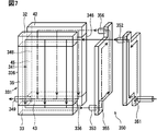
- the internal heat exchanger 350 is a plate-type heat exchanger, and is provided on the side plates 336 and 346.
- the evaporator 330 is composed of two heat exchangers, an upstream evaporator 331 and a downstream evaporator 341.
- Each of the upstream evaporator 331 and the downstream evaporator 341 is a multi-flow type heat exchanger having a plurality of pipes in which refrigerant flows.
- the upstream evaporator 331 is located upstream of the downstream evaporator 341 in the flow of the refrigerant sent from the compressor 2.
- the upstream evaporator 331 includes the upper tank part 32 and the lower tank part 33.
- the upper tank part 32 and the lower tank part 33 face each other, and an upstream core part 35 is provided between the upper tank part 32 and the lower tank part 33.
- the upstream core section 35 includes a plurality of flat tubes having a plurality of paths formed therein, and corrugated fins provided between the flat tubes.
- the upstream core section 35 provides an upstream heat exchange section for the evaporator 330.
- a side plate 336 for reinforcement is provided on the outermost side of the upstream core portion 35. The side plate 336 is provided over the upper tank part 32 and the lower tank part 33.
- the downstream evaporator 341 includes an upper tank part 42 and a lower tank part 43.
- the upper tank section 42 and the lower tank section 43 face each other, and a downstream core section 45 is provided between the upper tank section 42 and the lower tank section 43.
- the downstream core portion 45 includes a plurality of flat tubes having a plurality of paths formed therein, and corrugated fins provided between the flat tubes.
- the downstream outlet pipe 349 is connected to the lower tank portion 43.
- the downstream outlet pipe 349 functions as an outlet through which the refrigerant flows out of the evaporator 330.
- the downstream core section 45 provides a downstream heat exchange section of the evaporator 330.
- a side plate 346 for reinforcement is provided at the outermost side of the downstream core portion 45.
- the side plate 346 is provided over the upper tank part 42 and the lower tank part 43.
- the internal heat exchanger 350 includes an upstream plate 351 and a downstream plate 355.
- the upstream plate 351 and the downstream plate 355 each have a cavity formed therein, and constitute a refrigerant path so that the refrigerant flowing into the cavity spreads and flows over the entire cavity.
- the internal heat exchanger 350 is a plate-type heat exchanger in which the upstream plate 351 and the downstream plate 355 are overlapped in a state where they are in heat exchange with each other.
- the internal heat exchanger 350 includes an upstream inlet pipe 352 that connects the upstream plate 351 and the upper tank 32 of the upstream evaporator 331.
- the internal heat exchanger 350 includes an upstream outlet pipe 353 that communicates the downstream plate 355 with the lower tank 33 of the upstream evaporator 331.
- the internal heat exchanger 350 includes a downstream inlet pipe 356 that connects the downstream plate 355 and the upper tank section 42 of the downstream evaporator 341.
- the internal heat exchanger 350 is provided integrally with the evaporator 330 so as not to be detachable.
- arrows indicated by solid lines indicate the flow of the refrigerant before flowing out of the upstream evaporator 331.
- the arrow indicated by the two-dot chain line indicates the flow of the refrigerant after flowing out of the upstream evaporator 331.
- the refrigerant whose pressure has been reduced by the pressure reducing device 4 and whose temperature has decreased passes through the upstream plate 351 and flows into the upstream evaporator 331 from the upstream inlet pipe 352. At this time, the refrigerant exchanges heat with the refrigerant flowing through the downstream plate 355 while passing through the upstream plate 351.
- the refrigerant exchanges heat with outside air in the process of flowing through the upstream core section 35.
- the refrigerant having a low boiling point among the refrigerants forming the non-azeotropic mixed refrigerant evaporates more actively than the refrigerant having a high boiling point. Therefore, the refrigerant after flowing out of the upstream core portion 35 has a higher boiling point than the refrigerant before flowing into the upstream core portion 35.
- the flow of the refrigerant in the internal heat exchanger 350 will be described below.
- the refrigerant flowing out of the upstream evaporator 331 flows into the downstream plate 355 from the upstream outlet pipe 353.
- the refrigerant moves through the downstream plate 355 while being in contact with the outer surface of the upstream plate 351.
- the refrigerant and the refrigerant flowing through the upstream plate 351 exchange heat, and flow out of the internal heat exchanger 350 through the downstream inlet pipe 356.
- the refrigerant flows in a gas-liquid two-phase state.
- the refrigerant flowing in the upstream plate 351 is in a gas-liquid two-phase state in which the proportion of the liquid phase is large
- the refrigerant flowing in the downstream plate 355 is in a gas-liquid two-phase state in which the proportion of the gas phase is large.
- the refrigerant flowing through the upstream plate 351 and the refrigerant flowing through the downstream plate 355 exchange heat. That is, the low-temperature refrigerant flowing through the upstream plate 351 is heated by the high-temperature refrigerant flowing through the downstream plate 355, and the temperature rises.
- the high-temperature refrigerant flowing through the downstream plate 355 is cooled by the low-temperature refrigerant flowing through the upstream plate 351, and the temperature is reduced.
- the temperature of the refrigerant flowing into the upstream evaporator 331 and the temperature of the refrigerant flowing into the downstream evaporator 341 become substantially equal.
- the heat exchange using the internal heat exchanger 350 reduces the temperature gradient of the refrigerant.
- the refrigerant exchanges heat with external air in the process of flowing through the downstream core 45.
- the refrigerants forming the non-azeotropic mixed refrigerant not only the refrigerant having a small boiling point and a low proportion but also the refrigerant having a high boiling point which has not been evaporated very much in the upstream evaporator 331 is actively evaporated.
- the refrigerant flowing into the upstream evaporator 331 and the refrigerant flowing into the downstream evaporator 341 are heat-exchanged by using the internal heat exchanger 350. Therefore, the temperature distribution between the upstream evaporator 331 and the downstream evaporator 341 can be made almost the same, and the bias of the temperature distribution generated in the entire evaporator 330 can be reduced as compared with the case where the internal heat exchanger 350 is not used. Can be.
- the internal heat exchanger 350 is provided on the side plate 336 of the upstream evaporator 331 and the side plate 346 of the downstream evaporator 341. For this reason, the internal heat exchanger 350 is reinforced by the side plates 336, 346. Therefore, it is easy to prevent the internal heat exchanger 350 from being deformed or the like so that the heat cannot be appropriately exchanged between the refrigerants.
- the internal heat exchanger 350 is provided on the side plates 336 and 346 at positions avoiding the upstream core portion 35 and the downstream core portion 45 through which air passes. For this reason, the internal heat exchanger 350 does not deteriorate the pressure loss when air flows in the evaporator 330.
- the internal heat exchanger 350 is provided in the evaporator 330 so as to connect the upper tank sections 32 and 42 and the lower tank sections 33 and 43. For this reason, the internal heat exchanger 350 can fulfill the function of the side plates 336 and 346 in the evaporator 330. Therefore, of the side plates 336 and 346 provided on both sides, one side plate 336 and 346 can be the same component as the internal heat exchanger 350.
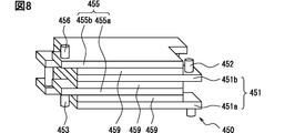
- the internal heat exchanger 450 is a stacked heat exchanger, and is configured integrally with the cold storage material 459.
- the internal heat exchanger 450 includes an upstream plate 451, a downstream plate 455, and a cold storage material 459.
- the upstream plate 451 and the downstream plate 455 have a cavity formed therein, and constitute a refrigerant path such that the refrigerant flowing into the inside spreads and flows as a whole.
- the upstream plate 451 includes two parts, a first upstream plate 451a and a second upstream plate 451b.
- the first upstream plate 451a and the second upstream plate 451b are connected by a pipe.
- the downstream plate 455 is composed of two parts, a first downstream plate 455a and a second downstream plate 455b.
- the first downstream plate 455a and the second downstream plate 455b are connected by a pipe.
- the first upstream plate 451a is provided with an upstream inlet pipe 452 connected to the upstream evaporator 31 and functioning as a refrigerant inlet of the upstream evaporator 31.
- the first downstream plate 455a includes an upstream outlet pipe 453 connected to the upstream evaporator 31 and functioning as a refrigerant outlet of the upstream evaporator 31.
- the second downstream plate 455b includes a downstream inlet pipe 456 that is connected to the downstream evaporator 41 and functions as a refrigerant inlet of the downstream evaporator 41.
- the internal heat exchanger 450 has a state in which the upstream plate 451 and the downstream plate 455 are alternately stacked, and the cold storage material 459 is sandwiched between the upstream plate 451 and the downstream plate 455 one by one. More specifically, from one surface to the opposite surface of the internal heat exchanger 450, the first upstream plate 451a, the cold storage material 459, the first downstream plate 455a, the cold storage material 459, the second upstream plate 451b, the cold storage material 459 and the second downstream plate 455b.
- the arrangement order of the components constituting the laminated internal heat exchanger 450 is not limited to the above-described configuration.
- the cold storage material 459 may be arranged at the outermost side and laminated.
- the cold storage material 459 is wound so as to cover the stacked upstream plate 451 and downstream plate 455 from the outside, and the internal heat exchanger 450 is provided. May be configured.
- arrows indicated by solid lines indicate the flow of the refrigerant before flowing out of the upstream evaporator 31.
- the arrows indicated by the two-dot chain lines indicate the flow of the refrigerant after flowing out of the upstream evaporator 31.
- the refrigerant whose pressure has been reduced by the pressure reducing device 4 and whose temperature has decreased flows into the first upstream plate 451a, spreads inside, and flows into the second upstream plate 451b through the pipe.
- the refrigerant that has flowed into the second upstream plate 451b spreads inside the second upstream plate 451b, and then flows through the upstream inlet pipe 452 toward the upstream evaporator 31 to flow out of the internal heat exchanger 450. I do.
- the refrigerant flowing through the upstream evaporator 31 passes through the upstream outlet pipe 453, flows into the first downstream plate 455a, spreads inside, and flows through the pipe into the second downstream plate 455b.
- the refrigerant that has flowed into the second downstream plate 455b spreads inside the second downstream plate 455b, and then flows through the downstream inlet pipe 456 toward the downstream evaporator 41 to flow out of the internal heat exchanger 450. I do.
- the non-azeotropic mixed refrigerants exchange heat with each other via the regenerator material 459 in the process of flowing through the internal heat exchanger 450. That is, the refrigerant having a low temperature flowing through the upstream plate 451 and the cold storage material 459 perform heat exchange, and the cold storage material 459 is cooled to decrease the temperature and increase the temperature of the refrigerant.
- the refrigerant having a high temperature flowing through the downstream plate 455 and the cold storage material 459 perform heat exchange, and the refrigerant flowing through the downstream plate 455 is cooled, so that the temperature of the refrigerant decreases and the temperature of the cold storage material 459 increases. That is, a temperature gradient caused by a change in the composition of the azeotropic mixed refrigerant can be reduced.
- the temperature of the cold storage material 459 that has exchanged heat with the refrigerant does not necessarily change. That is, a latent heat storage material that stores a change in heat exchanged by heat exchange with the refrigerant using a state change between the solid and the liquid of the cool storage material 459 may be used. By using a latent heat storage material, both the sensible heat and the latent heat can be stored, so that the size of the cold storage material 459 can be easily reduced.
- the internal heat exchanger 450 is a stacked heat exchanger in which the upstream plate 451 and the downstream plate 455 are stacked. Therefore, the heat exchange efficiency of the internal heat exchanger 450 can be easily adjusted by changing the number of stacked plates forming the internal heat exchanger 450.
- the internal heat exchanger 450 includes the cold storage material 459, and the refrigerant and the cold storage material 459 perform heat exchange. Therefore, it is easy for the internal heat exchanger 450 to maintain the refrigerant at an appropriate temperature by using the cold storage material 459. In other words, when the temperature of the refrigerant is too high, the refrigerant is cooled by the cold storage material 459, and when the temperature of the refrigerant is too low, the refrigerant is heated by the cold storage material 459. Therefore, the temperature of the refrigerant flowing into the upstream core portion 35 and the temperature of the refrigerant flowing into the downstream core portion 45 are appropriately managed, and a desired cooling performance can be easily obtained in the evaporator 30.
- the internal heat exchanger 450 may be arranged at a position away from the evaporator 30. According to this, since the position of the internal heat exchanger 450 can be freely designed, the degree of design freedom can be increased. This is particularly useful when it is necessary to arrange each component of the refrigeration cycle apparatus 1 in a limited space, such as when the refrigeration cycle apparatus 1 is mounted on a vehicle.
- the evaporator 30 divides the upstream core part 35 into two parts, the first core part 35a and the second core part 35b, has been described as an example, the number of divisions such as three divisions or four divisions may be increased. .
- the number of divisions of the downstream core section 45 is not limited to two as in the case of the upstream core section 35.
- the disclosure in this specification is not limited to the illustrated embodiment.
- the disclosure embraces the illustrated embodiments and variations thereon based on those skilled in the art.
- the disclosure is not limited to the combination of parts and / or elements shown in the embodiments.
- the disclosure can be implemented in various combinations.
- the disclosure may have additional parts that can be added to the embodiments.
- the disclosure encompasses embodiments that omit parts and / or elements.
- the disclosure encompasses the replacement or combination of parts and / or elements between one embodiment and another.
- the disclosed technical scope is not limited to the description of the embodiments.
Landscapes
- Engineering & Computer Science (AREA)
- Physics & Mathematics (AREA)
- Mechanical Engineering (AREA)
- Thermal Sciences (AREA)
- General Engineering & Computer Science (AREA)
- Heat-Exchange Devices With Radiators And Conduit Assemblies (AREA)
- Details Of Heat-Exchange And Heat-Transfer (AREA)
Abstract
Description
本出願は、当該開示内容が参照によって本出願に組み込まれた、2018年6月28日に出願された日本特許出願2018-123436号を基にしている。 This application is based on Japanese Patent Application No. 2018-123436 filed on June 28, 2018, the disclosure of which is incorporated herein by reference.
この明細書における開示は、冷凍サイクル装置に関する。 開 示 The disclosure in this specification relates to a refrigeration cycle device.
冷凍サイクルに用いられる冷媒には、環境負荷や冷却能力といった冷媒の特性が良好であることが求められている。良好な特性の冷媒を得る目的で、単一冷媒を用いる代わりに、異なる種類の冷媒を混合した混合冷媒を用いるものが知られている。ただし、高沸点冷媒と低沸点冷媒とを混合して得られた混合冷媒においては、蒸発器で沸点の低い冷媒から蒸発し、沸点の高い冷媒が後から蒸発する非共沸の混合冷媒となる場合がある。このため、非共沸混合冷媒を用いた蒸発器においては、蒸発器の冷媒流路における入口側と出口側との間で冷媒の蒸発温度が変化することで、蒸発器の温度分布に大きな偏りが生じてしまうことがあった。 冷媒 The refrigerant used for the refrigeration cycle is required to have good refrigerant characteristics such as environmental load and cooling capacity. In order to obtain a refrigerant having good characteristics, a refrigerant using a mixed refrigerant obtained by mixing different types of refrigerants instead of using a single refrigerant is known. However, in the mixed refrigerant obtained by mixing the high-boiling refrigerant and the low-boiling refrigerant, the low-boiling refrigerant evaporates in the evaporator, and the high-boiling refrigerant becomes a non-azeotropic mixed refrigerant that evaporates later. There are cases. For this reason, in an evaporator using a non-azeotropic refrigerant mixture, a change in the evaporation temperature of the refrigerant between the inlet side and the outlet side in the refrigerant flow path of the evaporator causes a large bias in the evaporator temperature distribution. Sometimes occurred.
この温度分布の偏りを低減するために、特許文献1では、非共沸混合冷媒用の熱交換器において、熱交換器の配管の中間部に流路断面積が減少する狭窄部を設けている。これにより、狭窄部がなければ出口側に向かって上昇する冷媒温度が、狭窄部によって略均一または出口側に向かって低下するようにして、温度分布の偏りを低減している。
In order to reduce the bias of the temperature distribution, in
従来技術の構成では、熱交換器の配管に狭窄部を設けることで、非共沸混合冷媒用の熱交換器で生じる温度分布の偏りを低減している。この場合、膨張弁やキャピラリチューブといった狭窄部を用いて、熱交換器を流れる冷媒の圧力を適切に調整する必要があった。上述の観点において、または言及されていない他の観点において、冷凍サイクル装置にはさらなる改良が求められている。 (4) In the configuration of the related art, the unevenness of the temperature distribution generated in the heat exchanger for the non-azeotropic mixed refrigerant is reduced by providing the constricted portion in the pipe of the heat exchanger. In this case, it is necessary to appropriately adjust the pressure of the refrigerant flowing through the heat exchanger by using a constricted portion such as an expansion valve or a capillary tube. In view of the above, or other aspects not mentioned, there is a need for further improvements in refrigeration cycle devices.
開示される1つの目的は、非共沸混合冷媒を用いた冷凍サイクルにおいて、蒸発器全体における温度分布の偏りを低減した冷凍サイクル装置を提供することにある。 One object of the disclosure is to provide a refrigeration cycle apparatus in which a non-azeotropic mixed refrigerant uses a refrigeration cycle in which the unevenness of the temperature distribution in the entire evaporator is reduced.
ここに開示された冷凍サイクル装置は、圧縮機と、凝縮器と、減圧装置と、蒸発器と、内部熱交換器とを備え、非共沸混合冷媒を循環させて冷却を行う冷凍サイクル装置であって、蒸発器は、内部を流れる非共沸混合冷媒と外部を流れる外部流体とを熱交換する上流熱交換部と、非共沸混合冷媒の流れにおいて上流熱交換部よりも下流に設けられ、内部を流れる非共沸混合冷媒と外部を流れる外部流体とを熱交換する下流熱交換部とを有している熱交換部を備え、内部熱交換器は、減圧装置を流出してから上流熱交換部に流入するまでの間を流れている非共沸混合冷媒と、上流熱交換部を流出してから下流熱交換部に流入するまでの間を流れている非共沸混合冷媒とを熱交換する。 The refrigeration cycle apparatus disclosed herein is a refrigeration cycle apparatus that includes a compressor, a condenser, a decompression device, an evaporator, and an internal heat exchanger, and performs cooling by circulating a non-azeotropic mixed refrigerant. The evaporator is provided with an upstream heat exchange section that exchanges heat between the non-azeotropic mixed refrigerant flowing inside and the external fluid flowing outside, and is provided downstream of the upstream heat exchange section in the flow of the non-azeotropic mixed refrigerant. A heat exchange unit having a non-azeotropic mixed refrigerant flowing inside and a downstream heat exchange unit for exchanging heat with an external fluid flowing outside, and the internal heat exchanger is upstream after flowing out of the pressure reducing device. The non-azeotropic mixed refrigerant flowing before flowing into the heat exchange section, and the non-azeotropic mixed refrigerant flowing from flowing out of the upstream heat exchange section to flowing into the downstream heat exchange section. Heat exchange.
開示された冷凍サイクル装置によると、減圧装置を流出してから上流熱交換部に流入するまでの間を流れている非共沸混合冷媒と、上流熱交換部を流出してから下流熱交換部に流入するまでの間を流れている非共沸混合冷媒とを熱交換する内部熱交換器を備えている。このため、非共沸混合冷媒を用いた冷凍サイクル装置において、上流熱交換部を流れたことで温度が上昇した冷媒と上流熱交換部に流入する前の冷媒とを内部熱交換器を用いて熱交換させることができる。その後、内部熱交換器での熱交換によって温度の低下した冷媒を下流熱交換部に流入させることで、内部熱交換器を備えない場合に比べて下流熱交換部における温度を下げて、上流熱交換部の温度と下流熱交換部の温度とを近づけることができる。したがって、非共沸混合冷媒を用いた冷凍サイクルにおいて、蒸発器全体における温度分布の偏りを低減した冷凍サイクル装置を提供できる。 According to the disclosed refrigeration cycle device, a non-azeotropic mixed refrigerant flowing from flowing out of the pressure reducing device to flowing into the upstream heat exchange portion, and flowing out of the upstream heat exchange portion and then downstream heat exchange portion And an internal heat exchanger for exchanging heat with the non-azeotropic mixed refrigerant flowing before flowing into the refrigerant. For this reason, in a refrigeration cycle device using a non-azeotropic mixed refrigerant, the refrigerant whose temperature has risen by flowing through the upstream heat exchange section and the refrigerant before flowing into the upstream heat exchange section are mixed using the internal heat exchanger. Can be heat exchanged. After that, by causing the refrigerant whose temperature has been reduced by heat exchange in the internal heat exchanger to flow into the downstream heat exchange section, the temperature in the downstream heat exchange section is reduced as compared with the case where the internal heat exchanger is not provided, and the upstream heat The temperature of the exchange section and the temperature of the downstream heat exchange section can be made close to each other. Therefore, in the refrigeration cycle using the non-azeotropic mixed refrigerant, it is possible to provide a refrigeration cycle apparatus in which the deviation of the temperature distribution in the entire evaporator is reduced.
図面を参照しながら、複数の実施形態を説明する。複数の実施形態において、機能的におよび/または構造的に対応する部分および/または関連付けられる部分には同一の参照符号、または百以上の位が異なる参照符号が付される場合がある。対応する部分および/または関連付けられる部分については、他の実施形態の説明を参照することができる。 複数 A plurality of embodiments will be described with reference to the drawings. In embodiments, functionally and / or structurally corresponding parts and / or associated parts may be provided with the same reference signs or reference signs that differ by more than a hundred places. For corresponding parts and / or associated parts, the description of the other embodiments can be referred to.
(第1実施形態)
冷凍サイクル装置1は、冷媒を用いて冷熱や温熱を作り出す装置である。冷凍サイクル装置1は、例えば車両に搭載されて車室内の冷房や暖房を行う車両用空調システムの一部として使用される。ただし、冷凍サイクル装置1は、車両用空調システム以外にも、家庭用の空調装置やサーバの冷却装置などの装置に対して広く適用可能である。
(1st Embodiment)
The
図1において、冷凍サイクル装置1は、圧縮機2と凝縮器3と減圧装置4と蒸発器30と内部熱交換器50とを備えている。冷凍サイクル装置1は、各部品を接続して非共沸混合冷媒が循環する流路を提供する冷媒流路20を備えている。
In FIG. 1, the
冷凍サイクル装置1においては、冷媒として非共沸混合冷媒を用いる。非共沸混合冷媒とは、異なる沸点を有する冷媒同士を混合したものであって、熱交換によって各冷媒の気液比率が変化して組成が変化する冷媒である。非共沸混合冷媒は、この組成変化によって沸点が変化する。非共沸混合冷媒においては、沸点の低い冷媒から先に蒸発することで、非共沸混合冷媒の組成が変化し、蒸発過程で冷媒全体としての沸点が徐々に上昇することとなる。したがって、非共沸混合冷媒を用いた場合、冷媒が蒸発する熱交換器の入口側において最も沸点が低く、出口側において最も沸点が高くなる。よって、適正に冷媒が蒸発している熱交換器においては、熱交換器の入口側の温度が最も低く、出口側に向かって徐々に温度が上昇するように温度勾配が生じることとなりやすい。
In the
圧縮機2は、気体の冷媒を圧縮して高温高圧の状態にする装置である。凝縮器3は、圧縮機2で圧縮された気体の冷媒を液体に凝縮する装置である。凝縮器3は、冷媒を凝縮させる過程で冷媒の熱を周囲に放熱して凝縮器3の周囲を加熱する熱交換器として機能する。減圧装置4は、冷媒の圧力を低下させて液体から気体に蒸発させやすくする装置である。減圧装置4としては、開度を調整することで冷媒を膨張させる膨張弁や、冷媒流路20に比べて内径の小さな管であるキャピラリチューブなどを用いることができる。蒸発器30は、減圧装置4で減圧された液体の冷媒を気体に蒸発させる装置である。蒸発器30は、冷媒を蒸発させる過程で周囲の外部流体から熱を奪って蒸発器30の周囲を冷却する熱交換器である。ここで、外部流体は例えば空気である。内部熱交換器50は、冷凍サイクル装置1を流れる冷媒同士を熱交換させる装置である。
The
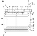
図2において、蒸発器30は、上流蒸発器31と下流蒸発器41との2つの熱交換器を並べて構成されている。上流蒸発器31と下流蒸発器41とは、ともに冷媒が流れる複数の配管を平行に備えたマルチフロータイプの熱交換器である。上流蒸発器31は、圧縮機2から送られた冷媒の流れにおいて、下流蒸発器41よりも上流に位置している。
In FIG. 2, the
上流蒸発器31は、上タンク部32と下タンク部33とを備えている。上タンク部32と下タンク部33とは対向している。上タンク部32の内部は、第1上タンク部32aと第2上タンク部32bとの2つの独立した領域に仕切られている。
The
上タンク部32と下タンク部33との間には、上流コア部35が設けられている。上流コア部35は、内部に複数の経路が形成された複数の扁平管と、扁平管同士の間に設けられた波形のコルゲートフィンとを備えている。上流コア部35は、第1コア部35aと第2コア部35bとの2つの領域に分割されている。第1コア部35aは、第1上タンク部32aと下タンク部33との間に設けられている。第2コア部35bは、第2上タンク部32bと下タンク部33との間に設けられている。上流コア部35は、蒸発器30の上流熱交換部を提供する。
上流 An
下流蒸発器41は、上タンク部42と下タンク部43とを備えている。上タンク部42と下タンク部43とは対向している。上タンク部42の内部は、第1上タンク部42aと第2上タンク部42bとの2つの独立した領域に仕切られている。第2上タンク部42bには下流出口管49が接続されており、蒸発器30から冷媒を流出させる出口として機能する。
The
上タンク部42と下タンク部43との間には、下流コア部45が設けられている。下流コア部45は、内部に複数の経路が形成された複数の扁平管と、扁平管同士の間に設けられた波形のコルゲートフィンとを備えている。下流コア部45は、第1コア部45aと第2コア部45bとの2つの領域に分割されている。第1コア部45aは、第1上タンク部42aと下タンク部43との間に設けられている。第2コア部45bは、第2上タンク部42bと下タンク部43との間に設けられている。下流コア部45は、蒸発器30の下流熱交換部を提供する。
下流 A
内部熱交換器50は、内管51と内管51の外側に設けられた外管55とを備えた二重管式の熱交換器である。内部熱交換器50は、内管51と上流蒸発器31の第1上タンク部32aとを連通している上流入口管52を備えている。内部熱交換器50は、外管55と上流蒸発器31の第2上タンク部32bとを連通している上流出口管53を備えている。内部熱交換器50は、外管55と下流蒸発器41の第1上タンク部42aとを連通している下流入口管56を備えている。内部熱交換器50は、上流蒸発器31の上タンク部32と下流蒸発器41の上タンク部42とにまたがるように蒸発器30の上部に位置している。言い換えると、内部熱交換器50は、蒸発器30から着脱不可能に一体に設けられている。
The
上流蒸発器31の上流コア部35と下流蒸発器41の下流コア部45とは、蒸発器30のコア部135を提供している。蒸発器30は、コア部135において空気と冷媒とを熱交換する。ただし、上流蒸発器31の上流コア部35の方が下流蒸発器41の下流コア部45よりも矢印F1方向に示す空気の流れの風下に位置している。したがって、蒸発器30において、空気は、下流コア部45で冷却された後、上流コア部35でさらに冷却されることとなる。コア部135は、蒸発器30の熱交換部を提供する。空気は、蒸発器30の外部を流れる外部流体を提供する。ただし、外部流体は気体の空気に限られず液体の水などを用いてもよい。
The
蒸発器30を構成する上流蒸発器31と内部熱交換器50と下流蒸発器41との3つの部分毎に蒸発器30における冷媒の流れを以下に示す。図3において、実線で示す矢印は、上流蒸発器31を流出するまでの冷媒の流れを示している。二点鎖線で示す矢印は、上流蒸発器31を流出してからの冷媒の流れを示している。減圧装置4で減圧され温度の低下した冷媒は、内管51を通過して上流入口管52から上流蒸発器31に流入する。この時、冷媒は、内管51を通過する過程で、外管55を流れる冷媒と熱交換を行う。
The flow of the refrigerant in the
上流蒸発器31における冷媒の流れを以下に説明する。冷媒は、第1上タンク部32aに流入した後、第1上タンク部32aの内部を広がって第1コア部35aを上から下に流れる。その後、冷媒は第1コア部35aと連通している下タンク部33に流入し、下タンク部33の内部を広がる。冷媒は、下タンク部33から流出して第2コア部35bを下から上に流れ、第2上タンク部32bに流入する。第2上タンク部32bに流入した冷媒は、上流出口管53を通過して上流蒸発器31の外部へと流出する。
The flow of the refrigerant in the
上流蒸発器31において、冷媒は、第1コア部35aと第2コア部35bとを流れる過程で外部の空気と熱交換を行う。これにより、非共沸混合冷媒をなす冷媒のうち、沸点の低い冷媒が沸点の高い冷媒に比べてより積極的に蒸発する。この蒸発によって冷媒の組成が変化して、第2コア部35bを流出した後の冷媒は、第1コア部35aに流入する前の冷媒に比べて沸点が上昇している。
(4) In the
内部熱交換器50における冷媒の流れを以下に説明する。上流蒸発器31を流出した冷媒は、上流出口管53から外管55の内部に流入する。冷媒は、外管55を流れることで内管51の外面と接触した状態で移動する。外管55を流れる過程で内管51を流れる冷媒と冷媒同士で熱交換を行い、下流入口管56を通過して内部熱交換器50の外部へと流出する。
The flow of the refrigerant in the
内部熱交換器50において、冷媒は、気液二相の状態で流れる。内管51を流れる冷媒は、液相の割合が大きな気液二相状態であり、外管55を流れる冷媒は、気相の割合が大きな気液二相状態である。内部熱交換器50において、内管51を流れる冷媒と外管55を流れる冷媒とが熱交換を行う。すなわち、内管51を流れる温度の低い冷媒は、外管55を流れる温度の高い冷媒によって加熱されて温度が上昇する。一方、外管55を流れる温度の高い冷媒は、内管51を流れる温度の低い冷媒によって冷却されて温度が低下する。これにより、上流蒸発器31に流入する冷媒と下流蒸発器41に流入する冷媒との温度が略等しい温度となる。言い換えると、内部熱交換器50を用いた熱交換により、冷媒の温度勾配が解消される。ここで、内部熱交換器50によって上流蒸発器31に流入する冷媒と下流蒸発器41に流入する冷媒との温度差が低下すればよく、冷媒の温度勾配を完全には解消しなくてもよい。
冷媒 In the
下流蒸発器41における冷媒の流れを以下に説明する。冷媒は、第1上タンク部42aに流入した後、第1上タンク部42aの内部を広がって第1コア部45aを上から下に流れる。その後、冷媒は第1コア部45aと連通している下タンク部43に流入し、下タンク部43の内部を広がる。冷媒は、下タンク部43から流出して第2コア部45bを下から上に流れ、第2上タンク部42bに流入する。第2上タンク部42bに流入した冷媒は、下流出口管49を通過して下流蒸発器41の外部へと流出する。
冷媒 The flow of the refrigerant in the
下流蒸発器41において、冷媒は、第1コア部45aと第2コア部45bとを流れる過程で外部の空気と熱交換を行う。これにより、非共沸混合冷媒をなす冷媒のうち、割合の少ない沸点の低い冷媒だけではなく、上流蒸発器31であまり蒸発しなかった沸点の高い冷媒も積極的に蒸発する。ここで、上流蒸発器31と同様に、入口から出口に向かう過程で、冷媒全体における沸点の高い冷媒が液相で存在する比率は上昇することとなる。
冷媒 In the
上述したように蒸発器30において、上流蒸発器31に流入する冷媒と下流蒸発器41に流入する冷媒とを内部熱交換器50を用いて熱交換させている。ここで、内部熱交換器50を用いた場合には、非共沸混合冷媒の特性によって発生した温度勾配を冷媒同士の熱交換により解消し、下流蒸発器41に流入する冷媒の温度が上流蒸発器31に流入する冷媒の温度と略等しい温度となる。一方、内部熱交換器50を用いない場合には、非共沸混合冷媒の特性によって発生した温度勾配が解消されず、下流蒸発器41に流入する冷媒の温度が上流蒸発器31に流入する冷媒の温度に比べて高い温度となる。したがって、内部熱交換器50を用いることで上流蒸発器31と下流蒸発器41との温度分布を同程度にすることができ、内部熱交換器50を用いない場合に比べて蒸発器30全体で生じる温度分布の偏りを低減することができる。
As described above, in the
また、温度勾配を考慮して蒸発器30の着霜を防止しようとすると、蒸発器30での冷却性能が低下してしまう。蒸発器30に着霜が引き起こされない最も低い冷媒の温度を0℃と仮定した場合に、蒸発器30において最も温度の低下しやすい入口側の冷媒温度を0℃とした状態が蒸発器30において最も冷却性能が高い状態である。ここで、全体での冷媒の温度勾配が5℃の蒸発器30においては、出口側の冷媒温度が5℃となるため、蒸発器30の温度を平均すると2.5℃となる。一方、全体での冷媒の温度勾配が10℃の蒸発器30においては、出口側の冷媒温度が10℃となるため、蒸発器30の温度を平均すると5℃となる。よって、蒸発器30全体での温度勾配が小さいほど、蒸発器30での平均温度を低下させて、蒸発器30の冷却性能を高めることができる。すなわち、内部熱交換器50を用いて蒸発器30全体での温度勾配を小さくすることで、蒸発器30での着霜を防止するとともに蒸発器30の冷却性能を高めることができる。
(4) If an attempt is made to prevent frost formation on the
上述した実施形態によると、非共沸混合冷媒同士を熱交換する内部熱交換器50を備えている。内部熱交換器50は、減圧装置4を流出してから上流蒸発器31の上流コア部35に流入するまでの間を流れている冷媒と、上流蒸発器31の上流コア部35を流出してから下流蒸発器41の下流コア部45に流入するまでの間を流れている冷媒とを熱交換する。言い換えると、コア部135を流れている途中で冷媒を抜き出して、コア部135に流入する前の冷媒と熱交換させてから再びコア部135に戻している。このため、蒸発器30の一部を流れたことで温度が上昇した冷媒を蒸発器30に流れる前の低い温度の冷媒で冷却し、冷却されて温度の低下した冷媒を再び蒸発器30に戻して蒸発させることができる。したがって、上流蒸発器31と下流蒸発器41との2つの熱交換器を備える蒸発器30において、非共沸混合冷媒の温度勾配による蒸発器30の温度分布の偏りを低減することができる。
According to the above-described embodiment, the
また、蒸発器30の全体での冷媒の温度勾配を低減できるため、蒸発器30の着霜を防止した状態で、高い冷却性能を発揮させやすい。言い換えると、冷媒として非共沸混合冷媒を用いることのデメリットを低減して、非共沸混合冷媒を含めた様々な冷媒の中から用途に応じて最適な冷媒を選択して冷凍サイクル装置1に使用することができる。
た め Further, since the temperature gradient of the refrigerant in the
内部熱交換器50は、蒸発器30と一体に設けられている。このため、蒸発器30と内部熱交換器50とを連通して冷媒が流れる配管を短くすることができる。したがって、冷凍サイクル装置1を小型化しやすい。
The
内部熱交換器50は、上流蒸発器31の上タンク部32及び下流蒸発器41の上タンク部42に設けられている。このため、蒸発器30における冷媒の入口及び出口と内部熱交換器50とを隣接させることができる。したがって、蒸発器30と内部熱交換器50とを連通して冷媒が流れる配管を短くして冷凍サイクル装置1を小型化しやすい。
The
また、空気が通過するコア部135を避けた位置である上流蒸発器31の上タンク部32及び下流蒸発器41の上タンク部42に内部熱交換器50が設けられている。このため、内部熱交換器50が蒸発器30において空気が流れる際の圧力損失を悪化させることがない。
The
内部熱交換器50は、内管51と外管55とを備えた二重管である。このため、内管51を流れる冷媒が、内部熱交換器50の周囲の空気と熱交換することで温められてしまうことを抑制できる。したがって、内部熱交換器50の周囲の空気の温度が高い場合であっても、蒸発器30に対して低温の冷媒を供給しやすい。ただし、外管55に上流蒸発器31に流入する前の液相の比率が大きな冷媒を流し、内管51に上流蒸発器31を流出した後の気相の比率が大きな冷媒を流すようにしてもよい。
The
上流熱交換部である上流コア部35は、下流熱交換部である下流コア部45よりも空気の流れの下流である風下に位置している。言い換えると、減圧装置4によって減圧された最も温度の低い冷媒が流入する上流蒸発器31の上流コア部35は、下流蒸発器41の下流コア部45よりも空気の流れの風下に位置している。このため、蒸発器30で熱交換される空気は、下流蒸発器41の下流コア部45で熱交換を行った後、より温度の低下しやすい上流蒸発器31の上流コア部35で熱交換を行う。したがって、風上に配置した温度の低い熱交換器で冷却された空気を、風下に配置した温度の高い熱交換器で加熱してしまうといった事態を防ぎやすい。言い換えると、風上から風下に向かって、下流蒸発器41、上流蒸発器31の順に空気の温度を段階的に下げるように冷却することができる。
上流 The
上流コア部35を流出した冷媒の冷却を上流コア部35に流入する前の冷媒との冷媒同士の熱交換によって行っている。このため、上流コア部35を流出した冷媒が上流コア部35に流入する前の冷媒よりも低温となることがない。したがって、減圧装置を用いて上流コア部35を流出した冷媒の温度を低下させる場合に比べて、下流コア部45への着霜を防止しやすい。
冷媒 Cooling of the refrigerant flowing out of the
外管55を内管51に沿うようにらせん状に設けてもよい。これによると、外管55における冷媒の流れを内管51の周囲全体と略均一に熱交換させることができる。このため、外管55の特定の部分に偏って冷媒が流れることで、内部熱交換器50での熱交換効率が低下してしまうことを低減できる。
The
上流蒸発器31と下流蒸発器41との冷却能力を異ならせてもよい。例えば、蒸発器30全体の冷却能力のうち、3分の2を上流蒸発器31で賄い、残りの3分の1を下流蒸発器41で賄うなどしてもよい。これによると、上流蒸発器31と下流蒸発器41のサイズを自由に設定することができる。また、上流蒸発器31をマルチフロータイプの熱交換器とし、下流蒸発器41をフィンチューブタイプの熱交換器とするなどして、異なる種類の熱交換器を用いて冷却能力を調整してもよい。
冷却 The cooling capacity of the
内管51や外管55の内側に内部フィンを設けて内管51を通過する冷媒と外管55を通過する冷媒との熱交換を促進させるようにしてもよい。また、内部熱交換器50を内管51と外管55とからなる二重管で構成する代わりに、管の内部を上下に仕切るなどして上流蒸発器31に流れ込む冷媒の経路と下流蒸発器41に流れ込む冷媒の経路とを形成してもよい。
内部 Internal fins may be provided inside the
(第2実施形態)
この実施形態は、先行する実施形態を基礎的形態とする変形例である。この実施形態では、内部熱交換器250が二重管ではなく、冷媒が流れる経路が交互に配置される構造である。
(2nd Embodiment)
This embodiment is a modified example based on the preceding embodiment. In this embodiment, the
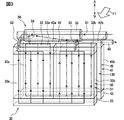
図4において、内部熱交換器250は、上流管251と下流管255とを備えた熱交換器である。上流管251は、上流蒸発器31に流入する前の冷媒が流れる配管である。下流管255は、上流蒸発器31を流出した後であって下流蒸発器41に流入する前の冷媒が流れる配管である。内部熱交換器250は、上流蒸発器31の上タンク部32と下流蒸発器41の上タンク部42とにまたがるように蒸発器30の上部に位置している。言い換えると、内部熱交換器250は、蒸発器30から着脱不可能に一体に設けられている。
に お い て In FIG. 4, the
内部熱交換器250は、上流管251と上流蒸発器31の第1上タンク部32aとを連通している上流入口管252を備えている。上流蒸発器31の第2上タンク部32bと内部熱交換器250の下流管255とは連通管253を用いて連通されている。
The
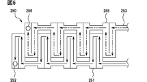
内部熱交換器250における冷媒の流れを以下に説明する。図5は、内部熱交換器250の水平方向の断面を上から下向きに見た場合の構成を示している。図5において、実線で示す矢印は、上流蒸発器31を流出するまでの冷媒の流れを示している。二点鎖線で示す矢印は、上流蒸発器31を流出してからの冷媒の流れを示している。内部熱交換器250は、下流管255と下流蒸発器41の第1上タンク部32aとを連通している下流入口管256を備えている。上流管251と下流管255とは、互いに接触した状態で蛇行して設けられている。
The flow of the refrigerant in the
減圧装置4で減圧され温度の低下した冷媒は、上流管251の内部を流れ、上流入口管252から上流蒸発器31に流入する。上流蒸発器31に流入した冷媒は、空気と熱交換して蒸発する。この蒸発により非共沸混合冷媒の組成が変化することで冷媒の温度が上昇する。上流蒸発器31を流出した冷媒は、上流管251を流れる冷媒に比べて温度が上昇した状態で連通管253を通過して下流管255に流入して、下流管255の内部を流れ、下流入口管256から下流蒸発器41に流入する。
(4) The refrigerant whose pressure has been reduced by the pressure reducing device 4 and whose temperature has decreased flows inside the
減圧装置4で減圧され温度の低下した冷媒と、上流蒸発器31を流れて温度の上昇した冷媒とは、内部熱交換器250を流れる過程で熱交換される。すなわち、上流管251を流れる温度の低い冷媒と下流管255を流れる温度の高い冷媒とが熱交換されて、2つの冷媒の温度が略等しい温度となった状態で上流入口管252または下流入口管256からそれぞれのコア部135に流入する。したがって、上流コア部35を流れる冷媒と下流コア部45を流れる冷媒とが略等しい温度となる。
(4) The refrigerant whose pressure has been reduced by the pressure reducing device 4 and whose temperature has decreased, and the refrigerant whose temperature has increased through the
上述した実施形態によると、内部熱交換器250は、上流管251と下流管255とを複数箇所で接触させて構成されている。このため、上流管251を流れる冷媒と下流管255を流れる冷媒とが熱交換しやすい。したがって、内部熱交換器250を用いた冷媒間の熱交換によって、冷媒同士の温度差を解消して、蒸発器30の温度勾配を解消しやすい。
According to the above-described embodiment, the
(第3実施形態)
この実施形態は、先行する実施形態を基礎的形態とする変形例である。この実施形態では、内部熱交換器350がプレート型の熱交換器であって、サイドプレート336、346に設けられている。
(Third embodiment)
This embodiment is a modified example based on the preceding embodiment. In this embodiment, the
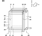
図6において、蒸発器330は、上流蒸発器331と下流蒸発器341との2つの熱交換器から構成されている。上流蒸発器331と下流蒸発器341とは、ともに冷媒が流れる複数の配管を平行に備えたマルチフロータイプの熱交換器である。上流蒸発器331は、圧縮機2から送られた冷媒の流れにおいて、下流蒸発器341よりも上流に位置している。
In FIG. 6, the
上流蒸発器331は、上タンク部32と下タンク部33とを備えている。上タンク部32と下タンク部33とは対向しており、上タンク部32と下タンク部33との間には、上流コア部35が設けられている。上流コア部35は、内部に複数の経路が形成された複数の扁平管と、その扁平管同士の間に設けられた波形のコルゲートフィンとを備えている。上流コア部35は、蒸発器330の上流熱交換部を提供する。上流コア部35の最外方には、補強のためのサイドプレート336が設けられている。サイドプレート336は、上タンク部32と下タンク部33とにまたがって設けられている。
The
下流蒸発器341は、上タンク部42と下タンク部43とを備えている。上タンク部42と下タンク部43とは対向しており、上タンク部42と下タンク部43との間には、下流コア部45が設けられている。下流コア部45は、内部に複数の経路が形成された複数の扁平管と、その扁平管同士の間に設けられた波形のコルゲートフィンとを備えている。下タンク部43には、下流出口管349が接続されている。下流出口管349は、蒸発器330から冷媒を流出させる出口として機能する。下流コア部45は、蒸発器330の下流熱交換部を提供する。下流コア部45の最外方には、補強のためのサイドプレート346が設けられている。サイドプレート346は、上タンク部42と下タンク部43とにまたがって設けられている。
The
内部熱交換器350は、上流プレート351と下流プレート355とを備えている。上流プレート351と下流プレート355とは、内部に空洞が形成されており、内部に流れ込んだ冷媒が空洞部分の全体に広がって流れるように冷媒経路を構成している。内部熱交換器350は、上流プレート351と下流プレート355とを互いに熱交換可能に接触させた状態で重ねたプレート式の熱交換器である。内部熱交換器350は、上流プレート351と上流蒸発器331の上タンク部32とを連通している上流入口管352を備えている。内部熱交換器350は、下流プレート355と上流蒸発器331の下タンク部33とを連通している上流出口管353を備えている。内部熱交換器350は、下流プレート355と下流蒸発器341の上タンク部42とを連通している下流入口管356を備えている。内部熱交換器350は、蒸発器330から着脱不可能に一体に設けられている。
The
蒸発器330を構成する上流蒸発器331と内部熱交換器350と下流蒸発器341とにおける冷媒の流れを以下に示す。図7において、実線で示す矢印は、上流蒸発器331を流出するまでの冷媒の流れを示している。二点鎖線で示す矢印は、上流蒸発器331を流出してからの冷媒の流れを示している。減圧装置4で減圧され温度の低下した冷媒は、上流プレート351を通過して上流入口管352から上流蒸発器331に流入する。この時、冷媒は、上流プレート351を通過する過程で、下流プレート355を流れる冷媒と熱交換を行う。
The flow of the refrigerant in the
上流蒸発器331に流入した冷媒は、上タンク部32の内部を広がって上流コア部35を上から下に流れる。その後、冷媒は上流コア部35と連通している下タンク部33に流入し、下タンク部33の内部を広がる。下タンク部33に流入した冷媒は、上流出口管53を通過して上流蒸発器331の外部へと流出する。
{Circle around (5)} The refrigerant flowing into the
上流蒸発器331において、冷媒は、上流コア部35を流れる過程で外部の空気と熱交換を行う。これにより、非共沸混合冷媒をなす冷媒のうち、沸点の低い冷媒が沸点の高い冷媒に比べてより積極的に蒸発する。よって、上流コア部35を流出した後の冷媒は、上流コア部35に流入する前の冷媒に比べて沸点が上昇している。
(4) In the
内部熱交換器350における冷媒の流れを以下に説明する。上流蒸発器331を流出した冷媒は、上流出口管353から下流プレート355の内部に流入する。冷媒は、下流プレート355を流れることで上流プレート351の外面と接触した状態で移動する。下流プレート355を流れる過程で上流プレート351を流れる冷媒と冷媒同士で熱交換を行い、下流入口管356を通過して内部熱交換器350の外部へと流出する。
冷媒 The flow of the refrigerant in the
内部熱交換器350において、冷媒は、気液二相の状態で流れる。上流プレート351を流れる冷媒は、液相の割合が大きな気液二相状態であり、下流プレート355を流れる冷媒は、気相の割合が大きな気液二相状態である。内部熱交換器350において、上流プレート351を流れる冷媒と下流プレート355を流れる冷媒とが熱交換を行う。すなわち、上流プレート351を流れる温度の低い冷媒は、下流プレート355を流れる温度の高い冷媒によって加熱されて温度が上昇する。一方、下流プレート355を流れる温度の高い冷媒は、上流プレート351を流れる温度の低い冷媒によって冷却されて温度が低下する。これにより、上流蒸発器331に流入する冷媒と下流蒸発器341に流入する冷媒との温度が略等しい温度となる。言い換えると、内部熱交換器350を用いた熱交換により、冷媒の温度勾配が低減される。
冷媒 In the
下流蒸発器41に流入した冷媒は、上タンク部42に流入した後、上タンク部42の内部を広がって下流コア部45を上から下に流れる。その後、冷媒は下流コア部45と連通している下タンク部43に流入し、下タンク部43の内部を広がり、下流出口管349を通過して下流蒸発器341の外部へと流出する。
(4) The refrigerant flowing into the
下流蒸発器341において、冷媒は、下流コア部45を流れる過程で外部の空気と熱交換を行う。これにより、非共沸混合冷媒をなす冷媒のうち、割合の少ない沸点の低い冷媒だけではなく、上流蒸発器331であまり蒸発しなかった沸点の高い冷媒も積極的に蒸発する。
(4) In the
上述したように蒸発器330において、上流蒸発器331に流入する冷媒と下流蒸発器341に流入する冷媒とを内部熱交換器350を用いて熱交換させている。したがって、上流蒸発器331と下流蒸発器341との温度分布を同程度にすることができ、内部熱交換器350を用いない場合に比べて蒸発器330全体で生じる温度分布の偏りを低減することができる。
As described above, in the
上述した実施形態によると、内部熱交換器350は、上流蒸発器331のサイドプレート336及び下流蒸発器341のサイドプレート346に設けられている。このため、内部熱交換器350がサイドプレート336、346によって補強される。したがって、内部熱交換器350が変形するなどして適切に冷媒同士を熱交換できなくなってしまうことを防止しやすい。
According to the above-described embodiment, the
また、空気が通過する上流コア部35と下流コア部45とを避けた位置であるサイドプレート336、346に内部熱交換器350が設けられている。このため、内部熱交換器350が蒸発器330において空気が流れる際の圧力損失を悪化させることがない。
{Circle around (2)} The
内部熱交換器350は、蒸発器330において、上タンク部32、42と下タンク部33、43とを接続するように設けられている。このため、内部熱交換器350が蒸発器330におけるサイドプレート336、346の機能を担うことができる。したがって、両側に設けられているサイドプレート336、346の内、片側のサイドプレート336、346を内部熱交換器350と同一の部品とすることができる。
The
(第4実施形態)
この実施形態は、先行する実施形態を基礎的形態とする変形例である。この実施形態では、内部熱交換器450が積層型の熱交換器であって、蓄冷材459と一体に構成されている。
(Fourth embodiment)
This embodiment is a modified example based on the preceding embodiment. In this embodiment, the
図8において、内部熱交換器450は、上流プレート451と下流プレート455と蓄冷材459とを備えている。上流プレート451と下流プレート455とは、内部に空洞が形成されており、内部に流れ込んだ冷媒が全体に広がって流れるように冷媒経路を構成している。上流プレート451は、第1上流プレート451aと第2上流プレート451bとの2つの部品から構成されている。第1上流プレート451aと第2上流プレート451bとは、配管で連通されている。下流プレート455は、第1下流プレート455aと第2下流プレート455bとの2つの部品から構成されている。第1下流プレート455aと第2下流プレート455bとは、配管で連通されている。
に お い て In FIG. 8, the
第1上流プレート451aは、上流蒸発器31と接続して上流蒸発器31の冷媒入口として機能する上流入口管452を備えている。第1下流プレート455aは、上流蒸発器31と接続して上流蒸発器31の冷媒出口として機能する上流出口管453を備えている。第2下流プレート455bは、下流蒸発器41と接続して下流蒸発器41の冷媒入口として機能する下流入口管456を備えている。
The first
内部熱交換器450は、上流プレート451と下流プレート455とが交互に積層されており、上流プレート451と下流プレート455との間に蓄冷材459が1枚ずつ挟まれた状態である。より詳細には、内部熱交換器450の一方の面から反対側の面までは、第1上流プレート451a、蓄冷材459、第1下流プレート455a、蓄冷材459、第2上流プレート451b、蓄冷材459、第2下流プレート455bの順に各部品が並んでいる。
(5) The
ただし、積層型の内部熱交換器450をなす各部品の並び順は、上述の構成に限られない。例えば蓄冷材459を最外方に配置して積層してもよい。あるいは、蓄冷材459を上流プレート451と下流プレート455との間に挟むのではなく、積層された上流プレート451と下流プレート455とを外側から覆うように蓄冷材459を巻き付けて内部熱交換器450を構成してもよい。
{However, the arrangement order of the components constituting the laminated
内部熱交換器450における冷媒の流れを以下に示す。図9において、実線で示す矢印は、上流蒸発器31を流出するまでの冷媒の流れを示している。二点鎖線で示す矢印は、上流蒸発器31を流出してからの冷媒の流れを示している。減圧装置4で減圧され温度の低下した冷媒は、第1上流プレート451aに流入して内部に広がり、配管を通って第2上流プレート451bに流れ込む。第2上流プレート451bの内部に流入した冷媒は、第2上流プレート451bの内部を広がった後、上流入口管452を通過して上流蒸発器31に向かって流れることで内部熱交換器450から流出する。
冷媒 The flow of the refrigerant in the
上流蒸発器31を流れた冷媒は、上流出口管453を通過して第1下流プレート455aに流入して内部に広がり、配管を通って第2下流プレート455bに流れ込む。第2下流プレート455bの内部に流入した冷媒は、第2下流プレート455bの内部を広がった後、下流入口管456を通過して下流蒸発器41に向かって流れることで内部熱交換器450から流出する。
冷媒 The refrigerant flowing through the
非共沸混合冷媒は、内部熱交換器450を流れる過程で互いに蓄冷材459を介して熱交換を行う。すなわち、上流プレート451を流れる温度の低い冷媒と蓄冷材459とが熱交換を行って、蓄冷材459が冷やされて温度が低下するとともに、冷媒の温度が上昇する。一方、下流プレート455を流れる温度の高い冷媒と蓄冷材459とが熱交換を行って、下流プレート455を流れる冷媒が冷やされて冷媒の温度が低下するとともに蓄冷材459の温度が上昇する。すなわち、共沸混合冷媒の組成の変化によって生じる温度勾配を低減できる。
The non-azeotropic mixed refrigerants exchange heat with each other via the
冷媒と熱交換を行った蓄冷材459は、必ずしも温度が変化しなくてもよい。すなわち、冷媒との熱交換でやり取りした熱の変化を蓄冷材459の固体と液体との間での状態変化を用いて蓄えるような潜熱蓄冷材を用いてもよい。潜熱蓄冷材を用いることで顕熱と潜熱の両方の熱を蓄えることができるため、蓄冷材459を小型化しやすい。
(4) The temperature of the
上述した実施形態によると、内部熱交換器450は、上流プレート451と下流プレート455とを積層した積層型の熱交換器である。このため、内部熱交換器450をなすプレートの積層枚数を変化させることで、内部熱交換器450における熱交換効率を容易に調整することができる。
According to the above-described embodiment, the
内部熱交換器450は、蓄冷材459を備えており、冷媒と蓄冷材459とが熱交換を行っている。このため、内部熱交換器450が蓄冷材459を用いて冷媒を適切な温度に維持させやすい。言い換えると、冷媒の温度が高すぎる場合には、冷媒が蓄冷材459によって冷却され、冷媒の温度が低すぎる場合には、冷媒が蓄冷材459によって加熱される。したがって、上流コア部35に流入する冷媒の温度と、下流コア部45に流入する冷媒の温度とを適切に管理して、蒸発器30で所望の冷却性能を得やすい。
(4) The
内部熱交換器450を蒸発器30から離れた位置に配置してもよい。これによると、内部熱交換器450の位置を自由に設計できるため、設計の自由度を高くすることができる。冷凍サイクル装置1を車両に搭載する場合など、限られた空間内に冷凍サイクル装置1の各構成部品を配置する必要がある場合に特に有用である。
The
(他の実施形態)
内部熱交換器50が上タンク部32、42と接続して蒸発器30の上部に設けられた場合を例に説明を行ったが、下タンク部33、43と接続して蒸発器30の下部に設けてもよい。
(Other embodiments)
The case where the
蒸発器30が上流コア部35を第1コア部35aと第2コア部35bとに二分割された場合を例に説明を行ったが、三分割や四分割など分割する数を増やしてもよい。下流コア部45についても、上流コア部35と同様に分割数は2つに限られない。
Although the case where the
この明細書における開示は、例示された実施形態に制限されない。開示は、例示された実施形態と、それらに基づく当業者による変形態様を包含する。例えば、開示は、実施形態において示された部品および/または要素の組み合わせに限定されない。開示は、多様な組み合わせによって実施可能である。開示は、実施形態に追加可能な追加的な部分をもつことができる。開示は、実施形態の部品および/または要素が省略されたものを包含する。開示は、1つの実施形態と他の実施形態との間における部品および/または要素の置き換え、または組み合わせを包含する。開示される技術的範囲は、実施形態の記載に限定されない。 開 示 The disclosure in this specification is not limited to the illustrated embodiment. The disclosure embraces the illustrated embodiments and variations thereon based on those skilled in the art. For example, the disclosure is not limited to the combination of parts and / or elements shown in the embodiments. The disclosure can be implemented in various combinations. The disclosure may have additional parts that can be added to the embodiments. The disclosure encompasses embodiments that omit parts and / or elements. The disclosure encompasses the replacement or combination of parts and / or elements between one embodiment and another. The disclosed technical scope is not limited to the description of the embodiments.
Claims (7)
前記蒸発器は、
内部を流れる非共沸混合冷媒と外部を流れる外部流体とを熱交換する上流熱交換部(35)と、非共沸混合冷媒の流れにおいて前記上流熱交換部よりも下流に設けられ、内部を流れる非共沸混合冷媒と外部を流れる外部流体とを熱交換する下流熱交換部(45)とを有している熱交換部(135)を備え、
前記内部熱交換器は、
前記減圧装置を流出してから前記上流熱交換部に流入するまでの間を流れている非共沸混合冷媒と、前記上流熱交換部を流出してから前記下流熱交換部に流入するまでの間を流れている非共沸混合冷媒とを熱交換する冷凍サイクル装置。 Non-azeotropic, comprising a compressor (2), a condenser (3), a decompression device (4), an evaporator (30, 330), and an internal heat exchanger (50, 250, 350, 450). A refrigeration cycle device (1) for cooling by circulating a mixed refrigerant,
The evaporator is
An upstream heat exchange section (35) for exchanging heat between the non-azeotropic mixed refrigerant flowing inside and the external fluid flowing outside; and an upstream heat exchange section provided downstream of the upstream heat exchange section in the flow of the non-azeotropic mixed refrigerant. A heat exchange unit (135) having a downstream heat exchange unit (45) for exchanging heat between the flowing non-azeotropic mixed refrigerant and an external fluid flowing outside;
The internal heat exchanger,
A non-azeotropic mixed refrigerant flowing from flowing out of the pressure reducing device to flowing into the upstream heat exchange section, and from flowing out of the upstream heat exchange section to flowing into the downstream heat exchange section. A refrigeration cycle device that exchanges heat with a non-azeotropic mixed refrigerant flowing between them.
前記内部熱交換器(50、250)は、前記タンク部に設けられている請求項2に記載の冷凍サイクル装置。 The evaporator includes a tank section (32, 42) communicating with the heat exchange section,
The refrigeration cycle apparatus according to claim 2, wherein the internal heat exchanger (50, 250) is provided in the tank unit.
前記内部熱交換器(350)は、前記サイドプレートに設けられている請求項2に記載の冷凍サイクル装置。 The evaporator includes side plates (336, 346) for reinforcing the heat exchange unit,
The refrigeration cycle apparatus according to claim 2, wherein the internal heat exchanger (350) is provided on the side plate.
Applications Claiming Priority (2)
| Application Number | Priority Date | Filing Date | Title |
|---|---|---|---|
| JP2018-123436 | 2018-06-28 | ||
| JP2018123436A JP7115069B2 (en) | 2018-06-28 | 2018-06-28 | refrigeration cycle equipment |
Publications (1)
| Publication Number | Publication Date |
|---|---|
| WO2020004221A1 true WO2020004221A1 (en) | 2020-01-02 |
Family
ID=68987107
Family Applications (1)
| Application Number | Title | Priority Date | Filing Date |
|---|---|---|---|
| PCT/JP2019/024496 Ceased WO2020004221A1 (en) | 2018-06-28 | 2019-06-20 | Refrigeration cycle apparatus |
Country Status (2)
| Country | Link |
|---|---|
| JP (1) | JP7115069B2 (en) |
| WO (1) | WO2020004221A1 (en) |
Citations (3)
| Publication number | Priority date | Publication date | Assignee | Title |
|---|---|---|---|---|
| JP2000055525A (en) * | 1998-08-17 | 2000-02-25 | Samsung Electronics Co Ltd | Refrigeration cycle device for refrigerator |
| JP2003302188A (en) * | 2002-04-11 | 2003-10-24 | Denso Corp | Heat exchanger |
| JP2010216778A (en) * | 2009-03-19 | 2010-09-30 | Hitachi Appliances Inc | Refrigerating cycle device |
Family Cites Families (2)
| Publication number | Priority date | Publication date | Assignee | Title |
|---|---|---|---|---|
| JP6323313B2 (en) | 2014-11-27 | 2018-05-16 | 株式会社デンソー | Evaporator unit |
| JP6341099B2 (en) | 2015-01-14 | 2018-06-13 | 株式会社デンソー | Refrigerant evaporator |
-
2018
- 2018-06-28 JP JP2018123436A patent/JP7115069B2/en active Active
-
2019
- 2019-06-20 WO PCT/JP2019/024496 patent/WO2020004221A1/en not_active Ceased
Patent Citations (3)
| Publication number | Priority date | Publication date | Assignee | Title |
|---|---|---|---|---|
| JP2000055525A (en) * | 1998-08-17 | 2000-02-25 | Samsung Electronics Co Ltd | Refrigeration cycle device for refrigerator |
| JP2003302188A (en) * | 2002-04-11 | 2003-10-24 | Denso Corp | Heat exchanger |
| JP2010216778A (en) * | 2009-03-19 | 2010-09-30 | Hitachi Appliances Inc | Refrigerating cycle device |
Also Published As
| Publication number | Publication date |
|---|---|
| JP7115069B2 (en) | 2022-08-09 |
| JP2020003147A (en) | 2020-01-09 |
Similar Documents
| Publication | Publication Date | Title |
|---|---|---|
| KR100905995B1 (en) | Air conditioner | |
| US8616012B2 (en) | Evaporator for a refrigeration circuit | |
| CN103959004B (en) | Heat exchanger | |
| CN101592411B (en) | Refrigeration cycle device | |
| JP6580451B2 (en) | Heat exchanger | |
| JP6042026B2 (en) | Refrigeration cycle equipment | |
| US9951996B2 (en) | Refrigerant evaporator | |
| US20160054038A1 (en) | Heat exchanger and refrigeration cycle apparatus | |
| JP5975971B2 (en) | Heat exchanger and refrigeration cycle apparatus | |
| JPWO2018029784A1 (en) | Heat exchanger and refrigeration cycle apparatus equipped with the heat exchanger | |
| CN105705898A (en) | Thermal energy storage assembly with phase change materials | |
| US20220412610A1 (en) | Cooling module using solid refrigerant and cooling system using solid refrigerant | |
| WO2018154957A1 (en) | Refrigeration cycle device | |
| WO2007034744A1 (en) | Air conditioner | |
| JP5526494B2 (en) | Refrigeration equipment | |
| WO2020004221A1 (en) | Refrigeration cycle apparatus | |
| JP2009133530A (en) | Heat exchanger and heat pump water heater using the same | |
| CN212378292U (en) | Air conditioner heat exchange system and heat regenerator | |
| JP2017036900A (en) | Radiator and super-critical pressure refrigerating-cycle using the radiator | |
| JP2002228299A (en) | Composite heat exchanger | |
| US11820199B2 (en) | Heat exchanger | |
| WO2018051611A1 (en) | Heat exchanger and heat pump system using same | |
| WO2018168698A1 (en) | Heat exchanging device and heat exchanging method | |
| JP2005009808A (en) | Air conditioner heat exchanger. | |
| EP3795928A1 (en) | Refrigeration cycle device |
Legal Events
| Date | Code | Title | Description |
|---|---|---|---|
| 121 | Ep: the epo has been informed by wipo that ep was designated in this application |
Ref document number: 19826815 Country of ref document: EP Kind code of ref document: A1 |
|
| NENP | Non-entry into the national phase |
Ref country code: DE |
|
| 122 | Ep: pct application non-entry in european phase |
Ref document number: 19826815 Country of ref document: EP Kind code of ref document: A1 |