WO2020004238A1 - Fibre optique à gainage multiple et procédé de fabrication de celle-ci - Google Patents
Fibre optique à gainage multiple et procédé de fabrication de celle-ci Download PDFInfo
- Publication number
- WO2020004238A1 WO2020004238A1 PCT/JP2019/024594 JP2019024594W WO2020004238A1 WO 2020004238 A1 WO2020004238 A1 WO 2020004238A1 JP 2019024594 W JP2019024594 W JP 2019024594W WO 2020004238 A1 WO2020004238 A1 WO 2020004238A1
- Authority
- WO
- WIPO (PCT)
- Prior art keywords
- optical fiber
- clad
- cladding layer
- core
- outer periphery
- Prior art date
- Legal status (The legal status is an assumption and is not a legal conclusion. Google has not performed a legal analysis and makes no representation as to the accuracy of the status listed.)
- Ceased
Links
Images










Classifications
-
- C—CHEMISTRY; METALLURGY
- C03—GLASS; MINERAL OR SLAG WOOL
- C03B—MANUFACTURE, SHAPING, OR SUPPLEMENTARY PROCESSES
- C03B37/00—Manufacture or treatment of flakes, fibres, or filaments from softened glass, minerals, or slags
- C03B37/01—Manufacture of glass fibres or filaments
- C03B37/012—Manufacture of preforms for drawing fibres or filaments
-
- G—PHYSICS
- G02—OPTICS
- G02B—OPTICAL ELEMENTS, SYSTEMS OR APPARATUS
- G02B6/00—Light guides; Structural details of arrangements comprising light guides and other optical elements, e.g. couplings
- G02B6/02—Optical fibres with cladding with or without a coating
-
- G—PHYSICS
- G02—OPTICS
- G02B—OPTICAL ELEMENTS, SYSTEMS OR APPARATUS
- G02B6/00—Light guides; Structural details of arrangements comprising light guides and other optical elements, e.g. couplings
- G02B6/02—Optical fibres with cladding with or without a coating
- G02B6/036—Optical fibres with cladding with or without a coating core or cladding comprising multiple layers
-
- H—ELECTRICITY
- H01—ELECTRIC ELEMENTS
- H01S—DEVICES USING THE PROCESS OF LIGHT AMPLIFICATION BY STIMULATED EMISSION OF RADIATION [LASER] TO AMPLIFY OR GENERATE LIGHT; DEVICES USING STIMULATED EMISSION OF ELECTROMAGNETIC RADIATION IN WAVE RANGES OTHER THAN OPTICAL
- H01S3/00—Lasers, i.e. devices using stimulated emission of electromagnetic radiation in the infrared, visible or ultraviolet wave range
- H01S3/05—Construction or shape of optical resonators; Accommodation of active medium therein; Shape of active medium
- H01S3/06—Construction or shape of active medium
- H01S3/063—Waveguide lasers, i.e. whereby the dimensions of the waveguide are of the order of the light wavelength
- H01S3/067—Fibre lasers
Definitions
- the present invention relates to a multi-clad optical fiber, a preform for an optical fiber, a method for producing a preform for an optical fiber, and a method for producing a multi-clad optical fiber, and more particularly to a method for producing a multi-clad optical fiber having a plurality of clad layers. Things.
- a double-clad optical fiber used in an optical amplifier, a fiber laser, or the like is known.
- this double clad optical fiber when excitation light propagating through the inner clad covered by the outer clad as a waveguide crosses the core, it excites rare earth ions in the core to amplify the signal light.
- the cross-sectional shape of the inner cladding is circular, a part of the excitation light spirals (skews) inside the inner cladding without passing through the core depending on the incident angle of the excitation light, and does not contribute to the excitation. It becomes skew mode light. If the skew mode light increases, the excitation efficiency deteriorates. Therefore, the cross-sectional shape of the inner cladding is made non-circular to scatter the skew mode light (for example, see Patent Document 1).
- the amount of rare earth elements added to the core tends to increase in order to increase the amount of amplification in such double clad optical fibers.
- the amount of the rare earth element is increased as described above, a component mainly composed of a rare earth oxide is crystallized in the core during the heat treatment for drawing the optical fiber base material during the production of the optical fiber, Separation phenomenon is likely to occur. When these phenomena occur, the structure of the core becomes inhomogeneous, so that light propagation loss increases. In order to suppress the crystallization and phase separation of such a rare earth oxide, it is necessary to sufficiently heat the core until it becomes homogeneous at the time of drawing.
- the present invention has been made in view of such problems of the related art, and has an effect of suppressing skew mode light in a cladding layer, and provides a multi-clad optical fiber having a small light transmission loss in a core. This is the first purpose.
- the present invention provides a method for producing a preform for an optical fiber, which has an effect of suppressing skew mode light in the cladding layer and can realize an optical fiber with small light transmission loss in the core. This is the third object.
- the present invention provides a method for manufacturing a multi-clad optical fiber which has an effect of suppressing skew mode light in the cladding layer and can obtain a multi-clad optical fiber having a small light transmission loss in the core. The purpose of.
- a multi-clad optical fiber having an effect of suppressing skew mode light in the cladding layer and having a small light transmission loss in the core.
- the multi-cladding optical fiber includes a core, a first cladding layer located outside the core, and a second cladding layer covering the outer periphery of the first cladding layer.
- the second cladding layer has a lower refractive index than that of the first cladding layer.
- On the outer periphery of the first cladding layer a plurality of concave portions that are recessed inward in the radial direction are formed so as to be separated from each other in the circumferential direction.
- a multi-clad optical fiber having an effect of suppressing skew mode light in a cladding layer and having a small light transmission loss in a core.
- the multi-cladding optical fiber includes a core, a first cladding layer located outside the core, and a second cladding layer covering the outer periphery of the first cladding layer.
- the second cladding layer has a lower refractive index than that of the first cladding layer.
- On the outer periphery of the first cladding layer a plurality of convex portions projecting outward in the radial direction are formed so as to be spaced apart from each other in the circumferential direction.
- an optical fiber preform that has an effect of suppressing skew mode light in a cladding layer and can realize an optical fiber with small light transmission loss in a core.
- This optical fiber preform includes a core portion and a clad portion located outside the core portion. A plurality of grooves depressed inward in the radial direction are formed on the outer periphery of the clad portion so as to be spaced apart from each other in the circumferential direction.
- an optical fiber preform having an effect of suppressing skew mode light in a cladding layer and capable of realizing an optical fiber having a small light transmission loss in a core.
- This optical fiber preform includes a core portion and a clad portion located outside the core portion. On the outer periphery of the clad portion, a plurality of projecting portions projecting outward in the radial direction are formed apart from each other in the circumferential direction.
- a preform for an optical fiber which has an effect of suppressing skew mode light in a cladding layer and can realize a multi-clad optical fiber with small light transmission loss in a core is manufactured.
- a method is provided. In this method, a glass material having a core portion and a clad portion located outside the core portion is prepared, and a plurality of grooves depressed inward in the radial direction are circumferentially separated from each other in the outer periphery of the glass material. Forming an optical fiber preform.
- a preform for an optical fiber which has an effect of suppressing skew mode light in a cladding layer and can realize a multi-clad optical fiber with small light transmission loss in a core is manufactured.
- a method is provided. In this method, a glass material having a core portion and a clad portion located outside the core portion is prepared, and the outer periphery of the glass material is processed into a polygonal column shape, and each side surface of the polygonal column of the glass material is formed. While leaving a part of the groove.
- the seventh aspect of the present invention there is provided a method of manufacturing a multi-clad optical fiber having an effect of suppressing skew mode light in a clad layer and capable of obtaining a multi-clad optical fiber having a small light transmission loss in a core.
- the optical fiber preform is manufactured by the method described above, and the manufactured optical fiber preform is heated and stretched, and the periphery of the clad portion of the stretched optical fiber preform is heated.
- a multi-clad optical fiber is manufactured by applying and curing a resin having a lower refractive index than the clad portion.
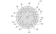
- FIG. 1 is a cross-sectional view schematically showing a double clad optical fiber according to the first embodiment of the present invention.
- FIG. 2 is a sectional view schematically showing a modification of the double clad optical fiber shown in FIG.
- FIG. 3 is a sectional view schematically showing another modified example of the double clad optical fiber shown in FIG.
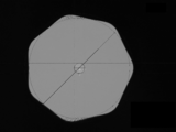
- FIG. 4 is a schematic diagram showing a cross-sectional shape perpendicular to the central axis of the inner cladding layer of the double clad optical fiber of FIG.
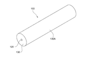
- FIG. 5 is a perspective view showing a glass material used for manufacturing the double clad optical fiber of FIG.
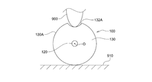
- FIG. 6 is a schematic view showing a step of forming a groove in the glass material of FIG. FIG.
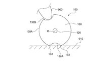
- FIG. 7 is a schematic diagram showing a state where the glass material is rotated after the process of FIG.
- FIG. 8 is a perspective view showing an optical fiber preform obtained by processing the glass material of FIG.
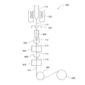
- FIG. 9 is a schematic diagram illustrating a drawing device used in the first embodiment of the present invention.
- FIG. 10 is a perspective view showing a glass material used for manufacturing a double clad optical fiber according to the second embodiment of the present invention.
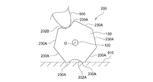
- FIG. 11 is a schematic view showing a step of forming a groove in the glass material of FIG.
- FIG. 12 is a schematic view showing a state where the glass material is rotated after the process of FIG.
- FIG. 13 is a perspective view schematically showing an optical fiber preform according to the second embodiment of the present invention.
- FIG. 14 is a schematic front view showing the optical fiber preform of FIG.
- FIG. 15 is a conceptual diagram for explaining the deepest groove that can be formed in the glass material shown in FIG.
- FIG. 16A is a micrograph showing a cross section of the double clad optical fiber according to the example of the present invention.
- FIG. 16B is a micrograph showing a cross section of the double clad optical fiber of Comparative Example 1.
- FIG. 16C is a micrograph showing a cross section of the double clad optical fiber of Comparative Example 2.
- FIGS. 1 to 16C a double clad optical fiber will be described as an example of a multi-clad optical fiber according to the present invention.
- the present invention can be applied to a multi-clad optical fiber having three or more clad layers.
- FIGS. 1 to 16C the same or corresponding components are denoted by the same reference numerals, and redundant description will be omitted. Also, in FIGS. 1 to 16C, the scale and size of each component may be exaggerated, or some components may be omitted.
- FIG. 1 is a cross-sectional view schematically showing a double clad optical fiber 10 according to the first embodiment of the present invention.
- the double clad optical fiber 10 according to the present embodiment includes a core 20 to which a rare earth element is added, an inner clad layer 30 (first clad layer) covering the outer periphery of the core 20, and an inner clad layer.
- An outer cladding layer (second cladding layer) that covers the outer periphery of the layer 30 and a coating layer that covers the outer periphery of the outer cladding layer are provided.
- the refractive index of the inner cladding layer 30 is lower than the refractive index of the core 20, so that the signal light propagates inside the core 20.
- the refractive index of the outer cladding layer 40 is lower than the refractive index of the inner cladding layer 30 so that the excitation light propagates inside the inner cladding layer 30.
- each recess 32 is formed by a curved surface, but may be formed by a plurality of planes (for example, in a V shape as shown in FIG. 2).
- each convex portion 34 is configured by a curved surface, but may be configured by a plurality of planes (for example, in an inverted V shape).
- the convex portion 34 protruding outward in the radial direction is formed between the adjacent concave portions 32, and the concave portion 32 concaved inward in the radial direction is formed between the adjacent convex portions 34.
- the space between the adjacent convex portions 34 may be formed by the flat surface 33 without forming the concave portion 32.
- the space between the adjacent concave portions 32 may be formed by a flat surface without forming the convex portions 34.
- the concave portions 32 are formed on the outer periphery of the inner clad layer 30, and the convex portions 34 are formed between these concave portions 32.
- the convex portions 34 are formed on the outer periphery of the inner cladding layer 30, and the concave portions 32 are formed between the convex portions 34. Therefore, the cross-sectional shape of the inner cladding layer 30 becomes non-circular. Therefore, it becomes difficult for the excitation light propagating in the inner cladding layer 30 to spiral spirally, and the propagation of the skew mode light in the inner cladding layer 30 is suppressed.
- the concave portion 32 and the convex portion 34 described above are maintained on the outer periphery of the inner clad layer even after the optical fiber base material is heated at a high temperature during manufacturing. Therefore, even when the amount of the rare earth element added to the core portion of the optical fiber preform is increased, it is possible to suppress the crystallization and phase separation of the rare earth oxide in the core 20 of the completed double clad optical fiber 10. As a result, light transmission loss is reduced.
- the convex portion 34 is formed by a curved surface, the portion formed by a plane in the inner cladding layer 30 is reduced, and cracks or chipping of the inner cladding layer 30 due to stress concentration that may occur on such a plane is eliminated. Can be suppressed.
- the protrusions 34 are formed between the adjacent recesses 32 so as to be continuous with the recesses 32.
- the convex portions 34 protruding outward in the radial direction are continuously formed in the adjacent concave portions 32, the convex portions 34 are smoothly connected to each other. And cracking or chipping of the inner cladding layer 30 due to stress concentration that can occur on such a plane can be suppressed.
- such a convex part 34 does not necessarily need to be formed continuously with the concave part 32.
- the concave portion 32 is formed between the adjacent convex portions 34 so as to be continuous with the convex portions 34.
- the convex portions 34 are smoothly connected to each other. It is possible to suppress cracking or chipping of the inner cladding layer 30 due to stress concentration that can occur on such a plane.
- such a concave portion 32 does not necessarily need to be formed continuously with the convex portion 34.
- FIG. 4 is a schematic diagram showing a cross-sectional shape of the inner cladding layer 30 perpendicular to the central axis O.
- a circle C1 inscribed in the outer shape of the cross section of the inner cladding layer 30 has a radius (radius R1) from the central axis O to a portion located inside the concave portion 32 of the inner cladding layer 30 in the most radial direction.
- the circle C2 circumscribing the outer shape of the cross section of the inner cladding layer 30 is a circle having a radius (radius R2) from the central axis O to a portion of the protrusion 34 of the inner cladding layer 30 located on the outermost side in the radial direction. .
- the ratio R1 / R2 of the radius R1 of the inscribed circle C1 to the radius R2 of the circumscribed circle C2 is large means that the cross-sectional shape of the inner cladding layer 30 approaches a circle, and as will be described later, In order to suppress the skew mode light propagating through 30, the smaller the radius ratio R1 / R2, the better.
- the radius ratio R1 / R2 is preferably 0.96 or less.
- a hollow quartz tube is prepared, and a necessary amount of a core component is deposited inside the quartz tube by, for example, an MCVD method to form a core portion.
- a cylindrical glass material 100 having the core part 120 and the clad part 130 located outside the core part 120 is obtained.
- the glass material 100 is fixed to a surface plate 910 of a machining center using hot wax or the like, and a diamond tool 900 having a curved end is set on the machining center.
- the groove 132A having a predetermined depth is formed along the longitudinal direction by moving in the axial direction while making contact with the cylindrical surface 130A.
- the glass material 100 is rotated around the central axis O so that the groove 132A faces the surface plate 910 of the machining center, and then the glass material 100 is again rotated. Is fixed to the surface plate 910. Then, the second groove 132B is formed by moving the diamond tool 900 in the axial direction while contacting the cylindrical surface 130A of the glass material 100.
- these steps of forming these grooves are performed seven times in total, and as shown in FIG. 8, the optical fiber preform 110 having seven grooves 132 recessed inward in the radial direction on the outer periphery is manufactured. These grooves 132 are formed at regular intervals in the circumferential direction, that is, at angular intervals of 2 ⁇ / 7.
- the preform 110 for an optical fiber is introduced into a drawing apparatus 800 as shown in FIG. 9 and drawn to manufacture the double clad optical fiber 10. That is, the optical fiber preform 110 is placed in a heating furnace 810 in a state where the optical fiber preform 110 is vertical, and the heating furnace 810 heats and melts the optical fiber preform 110. The optical fiber preform 110 that has been heated and melted is stretched in the vertical direction by its own weight to form a thread.
- the outer diameter of the fiber-shaped optical fiber material 111 is measured by the outer diameter monitor 820, it is introduced into the cooling pipe 830 and cooled.
- the cooled optical fiber material 112 is introduced into a first resin coating section 840, where a low refractive index resin is coated on the outer periphery.
- the optical fiber material 113 coated with the low-refractive-index resin is introduced into the first resin cured portion 850, where the low-refractive-index resin is cured by, for example, irradiation of ultraviolet rays, and the outer clad layer 40 (see FIG. 1). Is formed.
- the optical fiber material 114 on which the outer cladding layer 40 is formed is introduced into the second resin application section 860, where a coating resin is applied to the outer periphery.
- the optical fiber material 115 to which the coating resin has been applied is introduced into the second resin cured portion 870, where the coating resin is cured by, for example, irradiation of ultraviolet rays, and the coating layer 50 (see FIG. Ref) is formed.
- the optical fiber material 116 on which the coating layer 50 is formed is wound around the winding bobbin 890 at a predetermined speed by the capstan 880, and the double clad optical fiber 10 is completed.
- the optical fiber preform 110 Since a plurality of grooves 132 depressed inward in the radial direction are formed on the outer periphery of the optical fiber preform 110 manufactured by the above-described method, the optical fiber preform 110 is heated at a high temperature in the heating furnace 810. Even when heated, the concave portion 32 is formed in the inner clad layer 30 in the completed double clad optical fiber 10, and the cross-sectional shape of the inner clad layer 30 can be kept non-circular. In other words, the groove 132 of the optical fiber preform 110 changes into the concave portion 32 of the double clad optical fiber 10 by heating. Therefore, skew mode light in the inner cladding layer 30 can be effectively suppressed.
- the optical fiber preform 110 can be heated at a high temperature in this manner, even when the amount of the rare earth element added to the core portion 120 of the optical fiber preform 110 is increased, the completed double clad Crystallization and phase separation of the rare earth oxide in the core 20 of the optical fiber 10 can be suppressed, and light transmission loss can be reduced.
- a method for manufacturing a double-clad optical fiber according to the second embodiment of the present invention will be described.
- a necessary amount of a core component is deposited inside a hollow quartz tube by, for example, the MCVD method, and a glass material having a core portion 120 formed inside as shown in FIG.
- the cylindrical surface 130A of the glass material 100 is processed to obtain a regular heptagonal prism-shaped glass material 200 having seven side surfaces 230A as shown in FIG.
- Examples of the method of processing the cylindrical surface 130A of the glass material 100 include mechanical processing, laser processing, etching, and electrolytic polishing.
- the glass material 200 is fixed to the surface plate 910 using hot wax or the like while one side surface 230A of the glass material 200 is in contact with the surface plate 910 of the machining center.
- a groove 232A having a predetermined depth is formed along the longitudinal direction by moving in the axial direction while making contact with one side surface 230A of the glass material 200.
- the groove 232A may be formed in the side surface 230A while leaving a part of the side surface 230A of the glass material 200. In this case, the remaining side surface 230A is located on both sides of the formed groove 232A.
- the glass material 200 is rotated around the central axis O so that the groove 232A faces the surface plate 910 of the machining center, and then the glass material 200 is again formed. Is fixed to the surface plate 910.
- the second groove 232B is formed by moving the diamond tool 900 in the axial direction while making contact with another side surface 230A of the glass material 200.
- a groove 232B may be formed in the side surface 230A while leaving a part of the side surface 230A of the glass material 200.
- the step of forming these grooves is performed seven times in total, and as shown in FIGS. 13 and 14, the optical fiber base material 210 having seven grooves 232 recessed inward in the radial direction on the outer periphery is manufactured. .
- These grooves 232 are formed at regular intervals in the circumferential direction, that is, at angular intervals of 2 ⁇ / 7.
- optical fiber preform 210 is introduced into the drawing apparatus 800 shown in FIG. 9 and drawn in the same manner as in the first embodiment to manufacture a double clad optical fiber.
- the optical fiber preform 210 Since a plurality of grooves 232 recessed inward in the radial direction are formed on the outer periphery of the optical fiber preform 210 manufactured by the above-described method, the optical fiber preform 210 is heated at a high temperature in the heating furnace 810. Even when heated, a concave portion can be formed in the inner cladding layer of the completed double-clad optical fiber, and the cross-sectional shape of the inner cladding layer can be kept non-circular. In other words, the groove 232 of the optical fiber preform 210 changes into a concave portion of the double clad optical fiber by heating. Therefore, skew mode light in the inner cladding can be effectively suppressed.
- the optical fiber preform 210 can be heated at a high temperature in this manner, even when the amount of the rare earth element added to the core 220 of the optical fiber preform 210 is increased, the completed double clad Crystallization and phase separation of the rare earth oxide in the core of the optical fiber can be suppressed, and light transmission loss can be reduced.
- a plurality of protruding portions 234 protruding outward in the radial direction are formed on the outer periphery of the optical fiber preform 210 manufactured by the above-described method. Therefore, even if the optical fiber base material 210 is heated at a high temperature in the heating furnace 810, a convex portion is formed on the inner clad layer in the completed double-clad optical fiber, and the cross-sectional shape of the inner clad layer is kept non-circular. be able to. In other words, the protrusion 234 of the optical fiber preform 210 changes to a protrusion of the double clad optical fiber by heating. Therefore, skew mode light in the inner cladding layer can be effectively suppressed.
- the optical fiber preform can be heated at a high temperature in this manner, even when the amount of the rare earth element added to the core portion 120 of the optical fiber preform 210 is increased, the completed double clad light Crystallization and phase separation of the rare earth oxide in the fiber core can be suppressed, and light transmission loss can be reduced.
- the contact between the glass material 100 and the surface plate 910 makes contact with the edge 133 (FIG.
- the diamond tool 900 is pressed against the glass material 100 to perform grinding, stress concentrates on the edge 133 of the groove 132, and the glass material 100 is damaged or the completed double clad optical fiber is formed. It is considered that the strength of No. 10 is reduced.
- the cylindrical glass material 100 is formed into a regular heptagonal glass material 200 as shown in FIG. 10, while leaving a part of the side surface 230A of the regular heptagonal glass material 200, Since the groove 232 is formed on the side surface 230A, as shown in FIGS. 11 and 12, the contact between the glass material 200 and the surface plate 910 is caused by the entire side surface 230A or the side surface 230A remaining after the formation of the groove 232. Surface contact. Therefore, stress concentration when grinding is performed by pressing the diamond tool 900 against the glass material 100 is reduced, and damage to the glass material 200 and reduction in the strength of the double-clad optical fiber to be manufactured can be prevented.
- the side surface 230A remains after the groove 232 is formed on the side surface 230A of the glass material 200.
- the deepest groove 232 that can be formed in the glass material 200 is as shown in FIG.
- a circle C3 that forms the groove 232 in the cross section of the glass material 200 is formed when the vertices of the heptagon of the circle C3 pass through the central axis O.
- Equation (3) can be generalized to a preform for an optical fiber having an n prism, and the generalized equation is as shown in the following equation (4).
- R1 / R2 (1-sin ( ⁇ / n)) / cos ( ⁇ / n) (4)
- a double clad optical fiber was manufactured by the method according to the second embodiment described above.
- Yb was used as the rare earth element to be added to the core 20, and the addition amount was controlled so that the concentration of Yb was 3% by weight.
- the diamond tool 900 is pressed against each side surface 230A of the regular heptagonal prism-shaped glass material 200 to form the groove 232, the surface is deteriorated and roughened, so that it is cleaned by a chemical solution and processed by a flame.
- the surface was made transparent to produce an optical fiber preform 210.
- the groove 232 is formed by setting the ratio (side surface remaining ratio) of the side surface 230A of the glass material 100 to 2%, but the glass material 200 can be fixed on the surface plate 910 without any problem. did it. Also, no cracks or chips were found in the prepared optical fiber preform 210.
- the side surface residual ratio referred to here refers to the side surface of the glass material 200 after the formation of the groove 232 with respect to the region D1 (see FIG. 14) where the side surface 230A of the glass material 200 existed before the formation of the groove 232. It refers to the area ratio of the region (D1-D2) where 230A remains.
- D2 indicates a region where the side surface 230A of the glass material 200 does not exist after the groove 232 is formed.
- This optical fiber preform 210 was introduced into a drawing apparatus 800 and drawn to manufacture a double clad optical fiber. Specifically, the optical fiber preform 210 was placed in the heating furnace 810 in a vertical state, and the oxygen partial pressure in the heating furnace 810 was reduced by purging with an argon gas. Then, electric power of 20 kW was applied to the heating furnace 810 to heat and melt the distal end of the optical fiber preform 210. The melted optical fiber material was drawn at a predetermined tension and speed to obtain a double clad optical fiber.
- the first resin application section 840 an ultraviolet curable resin having a lower refractive index than that of the inner clad layer 30 is applied, and the first resin cured section 850 irradiates the ultraviolet curable resin with ultraviolet rays and cures the outer clad layer. Formed.
- the second resin application section 860 an ultraviolet curable resin was applied to the outside of the outer clad layer, and in the second resin cured section 870, the ultraviolet curable resin was irradiated with ultraviolet rays and cured to form a coating layer.
- the optical fiber material was rotated around the central axis to give a permanent twist to the optical fiber material.
- the rotation speed of the optical fiber material was controlled to be 4 rotations per 1 m of the length of the optical fiber material.
- Comparative Example 1 a double-clad optical fiber was manufactured using the heptagonal columnar glass material 200 shown in FIG. 10 as a base material for an optical fiber in the same manner as in the above-described example.
- the electric power supplied to the heating furnace 810 was set to 20 kW as in the above-described embodiment, and in Comparative Example 2, it was set to 18.5 kW.
- Example 2 For each of Example, Comparative Example 1, and Comparative Example 2, by measuring the optical transmission loss at a wavelength of 1180 nm using OTDR (Optical Time Domain Reflectometer) and measuring the absorption amount of the excitation light having a wavelength of 915 nm. The effect of suppressing skew mode light was evaluated. In the evaluation of the skew mode light suppressing effect, a skew suppressing index ⁇ calculated by the method described in Japanese Patent No. 6255532 was used. The larger the skew suppression index ⁇ , the more the occurrence of the skew mode is suppressed, and the maximum value is 1.
- FIGS. 16A, 16B, and 16C are photographs showing the cross sections of the double clad optical fibers of Example, Comparative Example 1, and Comparative Example 2, respectively. From these photographs, the radius R1 of the circle inscribed in the outer shape of the cross section perpendicular to the central axis of the inner cladding layer and the radius R2 of the circle circumscribed are obtained, and the ratio R1 / R1 of the radius R1 of the inscribed circle to the radius R2 of the circumscribed circle is obtained. R2 was calculated. In addition, R1 / R2 was similarly calculated for the optical fiber base material before drawing.
- the radius ratio R1 / R2 of the optical fiber preform was 0.901, but the completed optical fiber greatly increased to 0.972, and the skew suppression index ⁇ was increased. It has decreased to 0.92. This is presumably because the high-temperature heating by the heating furnace 810 rounded the corners of the heptagonal prism of the optical fiber preform, thereby reducing the radius R2 of the circumscribed circle and approaching R1 / R2 to one.
- the radius ratio R1 / R2 in the completed optical fiber was 0.959 in Comparative Example 2, which was processed at a lower temperature than that in Comparative Example 1, and did not increase as much as in Comparative Example 1.
- neither Comparative Example 1 nor Comparative Example 2 achieves both the reduction of the optical transmission loss and the effect of suppressing the skew.
- the embodiment realizes both the reduction of the optical transmission loss and the skew suppression effect. That is, in the embodiment, the optical transmission loss is reduced to 8 dB / km by increasing the temperature of the heating furnace 810, and the skew suppression index ⁇ is maintained at 1.00.
- the optical fiber base material 210 in the embodiment has the groove 232 recessed inward in the radial direction, so that the radius ratio R1 / R2 in the optical fiber base material 210 is reduced to 0.853. This is because even when the high-temperature heat treatment is performed, a concave portion is formed in the inner cladding layer in the completed optical fiber, so that the radius ratio R1 / R2 can be kept as small as 0.929.
- the radius ratio R1 / R2 in the manufactured optical fiber is preferably 0.96 or less.
- a base material for an optical fiber was manufactured with the side surface remaining rate of 0% when forming the groove 232 in the glass material 200, that is, without leaving the side surface 230A of the regular hexagonal prism.
- the ridge line of the prepared optical fiber preform was confirmed, cracks and chips having a size that could be visually confirmed were found in some places, but no cracks that propagated into the optical fiber preform were found.
- a double-clad optical fiber was manufactured from the optical fiber base material in the same manner as in the example.
- Example and Comparative Example 3 A 1% bending proof test was performed on a double-clad optical fiber having a length of 3 km. Although the double clad optical fiber of the example was broken twice, the morphology of the broken surface was a hackle pattern. As described above, in the example, a double-clad optical fiber having a sufficient length whose strength was guaranteed was obtained.
- the double clad optical fiber of Comparative Example 3 was frequently broken, and a mirror surface peculiar to the low-strength optical fiber was observed on the broken surface. In addition, it was confirmed that there was a fracture starting point at a portion corresponding to the ridge line of the heptagon.
- the side cladding ratio was set to 0% and the portion corresponding to the ridge of the heptagon was sharpened sharply, resulting in a low-strength, low-strength double-clad optical fiber. Conceivable.
- a double clad optical fiber was manufactured by drawing an optical fiber base material having a side surface residual ratio of 2% (the above example), 30%, 40%, and 100% (the above comparative example 1).
- the ratio R1 / R2 of the radius R1 of the inscribed circle to the radius R2 of the circumscribed circle and the skew suppression index ⁇ were calculated in the same manner as described above. Note that a power of 20 kW was supplied to the heating furnace 810.
- the grooves 132 and 232 are formed by mechanically processing the outer peripheral surfaces of the glass materials 100 and 200 using the diamond tool 900. A method of forming the grooves 132 and 232 is described. In addition to the mechanical processing, laser processing, etching, electrolytic polishing, and the like can be considered.
- the number of the concave portions 32 and the convex portions 34 formed in the inner cladding layer 30 and the number of the grooves 132 and 232 formed in the glass materials 100 and 200 are all seven. , These numbers may be 5, 6, 7, 8, or 9.
- a groove may be formed on each side surface of a pentagonal glass material, and five concave portions may be formed in an inner cladding layer of an optical fiber to be manufactured.
- the concave portions 32 and the convex portions described above may be provided on any clad layer disposed inside the clad layer having a relatively low refractive index.
- the part 34 can be formed.
- a multi-clad optical fiber having an effect of suppressing skew mode light in a cladding layer and having a small light transmission loss in a core.
- the multi-cladding optical fiber includes a core, a first cladding layer located outside the core, and a second cladding layer covering the outer periphery of the first cladding layer.
- the second cladding layer has a lower refractive index than that of the first cladding layer.
- On the outer periphery of the first cladding layer a plurality of concave portions that are recessed inward in the radial direction are formed so as to be separated from each other in the circumferential direction.
- the number of the plurality of recesses may be 5, 6, 7, 8, or 9.
- the recess may have a curved surface.
- the concave portion that is concave inward in the radial direction is formed on the outer periphery of the first cladding layer, the cross-sectional shape of the first cladding layer becomes non-circular. Therefore, the light propagating through the first cladding layer is less likely to spiral, and the propagation of the skew mode light through the first cladding layer is suppressed.
- the optical fiber preform is manufactured by heating at a high temperature, the above-described recess is maintained on the outer periphery of the first clad layer of the multi-clad optical fiber, and the skew mode light is suppressed.
- the amount of the rare earth element added to the core portion of the fiber preform is increased, the crystallization and phase separation of the rare earth oxide in the core of the multi-clad optical fiber can be suppressed by high-temperature heating. Therefore, light transmission loss in the multi-clad optical fiber is reduced.
- a convex portion having a curved surface and protruding outward in the radial direction is formed between the adjacent concave portions.
- the cross-sectional shape of the first cladding layer becomes more non-circular, so that propagation of skew mode light through the first cladding layer is more effectively suppressed.
- the convex portion has a curved surface, a portion formed by a plane in the first cladding layer is reduced, so that cracking or chipping of the first cladding layer due to stress concentration that can occur in such a plane can be suppressed.
- a convex portion protruding radially outward may be formed continuously with the adjacent concave portions.
- the convex portions projecting outward in the radial direction are continuously formed in the adjacent concave portions, the convex portions are smoothly connected to each other. Further, cracks and chipping of the first cladding layer due to stress concentration that can occur on such a plane can be suppressed.
- a multi-clad optical fiber having an effect of suppressing skew mode light in a cladding layer and having a small light transmission loss in a core.
- the multi-cladding optical fiber includes a core, a first cladding layer located outside the core, and a second cladding layer covering the outer periphery of the first cladding layer.
- the second cladding layer has a lower refractive index than that of the first cladding layer.
- On the outer periphery of the first cladding layer a plurality of convex portions projecting outward in the radial direction are formed so as to be spaced apart from each other in the circumferential direction.
- the number of the plurality of protrusions may be 5, 6, 7, 8, or 9.
- the convex portion projecting outward in the radial direction is formed on the outer periphery of the first clad layer, the cross-sectional shape of the first clad layer is non-circular. Therefore, the light propagating through the first cladding layer is less likely to spiral, and the propagation of the skew mode light through the first cladding layer is suppressed.
- the optical fiber preform is manufactured by heating at a high temperature, the above-described convex portion is maintained on the outer periphery of the first cladding layer of the multi-clad optical fiber, and the skew mode light is suppressed.
- the amount of the rare earth element added to the core of the optical fiber preform is increased, the crystallization and phase separation of the rare earth oxide in the core of the multi-clad optical fiber can be suppressed by high-temperature heating. Therefore, light transmission loss in the multi-clad optical fiber is reduced.
- a concave portion having a curved surface and concave inward in the radial direction is formed between the adjacent concave portions.
- Such a concave portion makes the cross-sectional shape of the first cladding layer more non-circular, so that the propagation of skew mode light through the first cladding layer is more effectively suppressed.
- a concave portion may be formed between the adjacent convex portions, the concave portion being recessed radially inward from the adjacent convex portion.
- the concave portion is smoothly connected to each other, so that the portion constituted by the flat surface in the first cladding layer is reduced. Further, cracks and chipping of the first cladding layer due to stress concentration that can occur on such a plane can be suppressed.
- the convex portion may have a curved surface.
- a portion formed by a plane in the first cladding layer is reduced, and cracking or chipping of the first cladding layer due to stress concentration that can occur in such a plane is suppressed. it can.
- a cross section perpendicular to the central axis of the first cladding layer is required.
- the ratio of the radius of the circle inscribed in the outer shape to the radius of the circle circumscribed in the outer shape is 0.96 or less.
- an optical fiber preform that has an effect of suppressing skew mode light in a cladding layer and can realize an optical fiber with small light transmission loss in a core.
- This optical fiber preform includes a core portion and a clad portion located outside the core portion. A plurality of grooves depressed inward in the radial direction are formed on the outer periphery of the clad portion so as to be spaced apart from each other in the circumferential direction.
- the optical fiber preform is heated at a high temperature during drawing.
- the completed optical fiber can hold a concave portion that is recessed radially inward in the clad layer, and the cross-sectional shape of the clad layer can be made non-circular. Therefore, it is difficult for the light propagating through the clad layer to spiral spirally, and the propagation of the skew mode light through the clad layer is suppressed.
- the optical fiber preform can be heated at a high temperature in this manner, even when the amount of the rare earth element added to the core portion of the optical fiber preform is increased, the finished optical fiber core can be heated. Crystallization and phase separation of the rare earth oxide can be suppressed, and light transmission loss can be reduced.
- the plurality of grooves may be composed of n grooves, and n may be 5, 6, 7, 8, or 9.
- the ratio of the radius of the circle circumscribed to the outer shape to the radius of the circle circumscribed to the outer shape of the cross section perpendicular to the center axis of the clad portion is (1-sin ( ⁇ / n)) / cos ( ⁇ / n) or more.
- an optical fiber preform having an effect of suppressing skew mode light in a cladding layer and capable of realizing an optical fiber having a small light transmission loss in a core.
- This optical fiber preform includes a core portion and a clad portion located outside the core portion. On the outer periphery of the clad portion, a plurality of projecting portions projecting outward in the radial direction are formed apart from each other in the circumferential direction.
- the optical fiber preform is heated at a high temperature during drawing.
- the completed optical fiber can hold the protrusion protruding radially outward on the cladding layer, and the cross-sectional shape of the cladding layer can be made non-circular. Therefore, it is difficult for the light propagating through the clad layer to spiral spirally, and the propagation of the skew mode light through the clad layer is suppressed.
- the optical fiber preform can be heated at a high temperature in this manner, even when the amount of the rare earth element added to the core portion of the optical fiber preform is increased, the finished optical fiber core can be heated. Crystallization and phase separation of the rare earth oxide can be suppressed, and light transmission loss can be reduced.
- the protruding portion is formed by a surface constituting a part of a side surface of the polygonal prism.
- the contact between the surface plate used for forming the protruding portion and the optical fiber preform can be a surface contact, and the stress concentration at the time of forming the protruding portion can be made. Can be alleviated. Therefore, it is possible to prevent the preform for the optical fiber from being damaged and the strength of the manufactured multi-clad optical fiber from being reduced.
- a preform for an optical fiber which has an effect of suppressing skew mode light in a cladding layer and can realize a multi-clad optical fiber with small light transmission loss in a core is manufactured.
- a method is provided. In this method, a glass material having a core portion and a clad portion located outside the core portion is prepared, and a plurality of grooves depressed inward in the radial direction are circumferentially separated from each other in the outer periphery of the glass material. Forming an optical fiber preform.
- the optical fiber preform can be heated at a high temperature in this manner, even when the amount of the rare earth element added to the core of the optical fiber preform is increased, the multi-clad optical fiber produced The crystallization and phase separation of the rare earth oxide in the core can be suppressed, and a multi-clad optical fiber with small light transmission loss can be obtained.
- the outer periphery of the glass material may be processed to have a polygonal column shape.
- the groove when forming the groove on the outer periphery of the glass material, the groove may be formed on the side surface while leaving a part of each side surface of the polygonal prism. In this way, when forming a groove on the outer periphery of the glass material, the contact between the surface plate used for forming the groove and the glass material becomes a surface contact, so that stress concentration when forming the groove is performed. Is reduced, and damage to the optical fiber base material and reduction in the strength of the double-clad optical fiber to be produced can be prevented.
- the groove When forming the groove on the outer periphery of the glass material, the groove may be formed on a cylindrical surface of the glass material.
- a preform for an optical fiber which has an effect of suppressing skew mode light in a cladding layer and can realize a multi-clad optical fiber with small light transmission loss in a core is manufactured.
- a method is provided. In this method, a glass material having a core portion and a clad portion located outside the core portion is prepared, and the outer periphery of the glass material is processed into a polygonal column shape, and each side surface of the polygonal column of the glass material is formed. While leaving a part of the groove.
- the optical fiber preform can be heated at a high temperature in this manner, even when the amount of the rare earth element added to the core of the optical fiber preform is increased, the multi-clad optical fiber produced The crystallization and phase separation of the rare earth oxide in the core can be suppressed, and a multi-clad optical fiber with small light transmission loss can be obtained.
- the seventh aspect of the present invention there is provided a method of manufacturing a multi-clad optical fiber having an effect of suppressing skew mode light in a clad layer and capable of obtaining a multi-clad optical fiber having a small light transmission loss in a core.
- the optical fiber preform is manufactured by the method described above, and the manufactured optical fiber preform is heated and stretched, and the periphery of the clad portion of the stretched optical fiber preform is heated.
- a multi-clad optical fiber is manufactured by applying and curing a resin having a lower refractive index than the clad portion.
- skew mode light in the cladding layer can be effectively suppressed, and light transmission loss in the core can be reduced.
- the present invention is suitably used for a multi-clad optical fiber having a plurality of clad layers.
- Double-clad optical fiber (multi-clad optical fiber) Reference Signs List 20 core 30 inner cladding layer 32 concave part 34 convex part 40 outer cladding layer 50 coating layer 100 glass material 110 optical fiber base material 120 core part 130 clad part 130A cylindrical surface 132 groove 200 glass material 210 optical fiber base material 220 core part 230A side surface 232 groove 800 wire drawing device 810 heating furnace 820 outer diameter monitor 830 cooling pipe 840 first resin coating section 850 first resin curing section 860 second resin coating section 870 second resin curing section 880 capstan 890 winding Taking bobbin 900 Diamond tool 910 Surface plate O Central axis
Landscapes
- Physics & Mathematics (AREA)
- Optics & Photonics (AREA)
- Engineering & Computer Science (AREA)
- General Physics & Mathematics (AREA)
- Electromagnetism (AREA)
- Chemical & Material Sciences (AREA)
- Life Sciences & Earth Sciences (AREA)
- General Life Sciences & Earth Sciences (AREA)
- Geochemistry & Mineralogy (AREA)
- Manufacturing & Machinery (AREA)
- Plasma & Fusion (AREA)
- Materials Engineering (AREA)
- Organic Chemistry (AREA)
- Lasers (AREA)
Abstract
La présente invention concerne une fibre optique à gainage multiple ayant pour effet de supprimer la lumière en mode oblique dans une couche à gainage et ayant peu de perte de transmission optique dans un cœur. Une fibre optique à double gainage 10 comprend un cœur 20, une couche à gainage intérieure 30 disposée à l'extérieur du cœur 20, et une couche à gainage extérieure 40 qui recouvre la périphérie extérieure de la couche à gainage intérieure 30. La couche à gainage extérieure 40 possède un indice de réfraction inférieur à celui de la couche à gainage intérieure 30. Au niveau de la périphérie extérieure de la couche à gainage intérieure 30, de multiples évidements 32 sont formés dans la direction circonférentielle de façon à être séparés les uns par rapport aux autres, les évidements étant en retrait dans le sens radial vers l'intérieur.
Applications Claiming Priority (4)
| Application Number | Priority Date | Filing Date | Title |
|---|---|---|---|
| JP2018-119844 | 2018-06-25 | ||
| JP2018-119568 | 2018-06-25 | ||
| JP2018119844 | 2018-06-25 | ||
| JP2018119568 | 2018-06-25 |
Publications (1)
| Publication Number | Publication Date |
|---|---|
| WO2020004238A1 true WO2020004238A1 (fr) | 2020-01-02 |
Family
ID=68984981
Family Applications (1)
| Application Number | Title | Priority Date | Filing Date |
|---|---|---|---|
| PCT/JP2019/024594 Ceased WO2020004238A1 (fr) | 2018-06-25 | 2019-06-20 | Fibre optique à gainage multiple et procédé de fabrication de celle-ci |
Country Status (1)
| Country | Link |
|---|---|
| WO (1) | WO2020004238A1 (fr) |
Citations (9)
| Publication number | Priority date | Publication date | Assignee | Title |
|---|---|---|---|---|
| JPH02273728A (ja) * | 1989-04-17 | 1990-11-08 | Nippon Telegr & Teleph Corp <Ntt> | 機能性光導波媒体 |
| JPH09194225A (ja) * | 1995-11-22 | 1997-07-29 | Lucent Technol Inc | クラッディングポンプファイバとその製造方法 |
| JP2002055244A (ja) * | 2000-04-10 | 2002-02-20 | Lucent Technol Inc | 光ファイバおよびそれにおいて使用されるクラッド物品 |
| JP2002277647A (ja) * | 2001-03-19 | 2002-09-25 | Mitsubishi Cable Ind Ltd | ダブルクラッドファイバの製造方法及びダブルクラッドファイバ |
| JP2003226540A (ja) * | 2002-02-04 | 2003-08-12 | Mitsubishi Cable Ind Ltd | ダブルクラッドファイバの製造方法 |
| JP2003229617A (ja) * | 2002-02-04 | 2003-08-15 | Mitsubishi Cable Ind Ltd | ダブルクラッドファイバ及びその製造方法 |
| CN102183813A (zh) * | 2011-05-09 | 2011-09-14 | 北京交通大学 | 带有聚光层的光纤结构 |
| JP2013214699A (ja) * | 2012-03-05 | 2013-10-17 | Mitsubishi Cable Ind Ltd | ダブルクラッド光ファイバ |
| WO2018003574A1 (fr) * | 2016-06-30 | 2018-01-04 | 株式会社フジクラ | Fibre optique pour amplification et dispositif laser |
-
2019
- 2019-06-20 WO PCT/JP2019/024594 patent/WO2020004238A1/fr not_active Ceased
Patent Citations (9)
| Publication number | Priority date | Publication date | Assignee | Title |
|---|---|---|---|---|
| JPH02273728A (ja) * | 1989-04-17 | 1990-11-08 | Nippon Telegr & Teleph Corp <Ntt> | 機能性光導波媒体 |
| JPH09194225A (ja) * | 1995-11-22 | 1997-07-29 | Lucent Technol Inc | クラッディングポンプファイバとその製造方法 |
| JP2002055244A (ja) * | 2000-04-10 | 2002-02-20 | Lucent Technol Inc | 光ファイバおよびそれにおいて使用されるクラッド物品 |
| JP2002277647A (ja) * | 2001-03-19 | 2002-09-25 | Mitsubishi Cable Ind Ltd | ダブルクラッドファイバの製造方法及びダブルクラッドファイバ |
| JP2003226540A (ja) * | 2002-02-04 | 2003-08-12 | Mitsubishi Cable Ind Ltd | ダブルクラッドファイバの製造方法 |
| JP2003229617A (ja) * | 2002-02-04 | 2003-08-15 | Mitsubishi Cable Ind Ltd | ダブルクラッドファイバ及びその製造方法 |
| CN102183813A (zh) * | 2011-05-09 | 2011-09-14 | 北京交通大学 | 带有聚光层的光纤结构 |
| JP2013214699A (ja) * | 2012-03-05 | 2013-10-17 | Mitsubishi Cable Ind Ltd | ダブルクラッド光ファイバ |
| WO2018003574A1 (fr) * | 2016-06-30 | 2018-01-04 | 株式会社フジクラ | Fibre optique pour amplification et dispositif laser |
Similar Documents
| Publication | Publication Date | Title |
|---|---|---|
| JP7794792B2 (ja) | 中空コア光ファイバおよびレーザシステム | |
| JP7535557B2 (ja) | モード混合光ファイバ、ならびにそれを用いた方法及びシステム | |
| JP6402466B2 (ja) | マルチコア光ファイバの製造方法 | |
| US9352996B2 (en) | Optical fiber article for handling higher power and method of fabricating or using | |
| CA2956941C (fr) | Assemblage de fibre optique a filtrage ameliore de modes d'ordre superieur | |
| JP6417710B2 (ja) | 屈曲光ファイバ製造方法 | |
| US8031999B2 (en) | Photonic band-gap fiber | |
| RU2437129C1 (ru) | Способ изготовления двулучепреломляющего микроструктурного оптического волокна | |
| CN105765427A (zh) | 弯曲光纤的制造方法 | |
| CN115136046A (zh) | 多芯光纤、多芯光纤带、多芯光纤的制造方法及处理方法 | |
| JP5676152B2 (ja) | 光ファイバ及びその製造方法 | |
| JP5949016B2 (ja) | 光ファイバ製造方法 | |
| JP2009129989A (ja) | ファイバレーザ用光ファイバ及びその製造方法、並びにファイバレーザ | |
| WO2020004238A1 (fr) | Fibre optique à gainage multiple et procédé de fabrication de celle-ci | |
| JP7584258B2 (ja) | 回転光ビーム発生装置 | |
| CN117023969B (zh) | 一种光纤预制棒、模式扰动光纤及其制备方法 | |
| JP6666882B2 (ja) | シングルコア光ファイバ用母材の製造方法、及び、シングルコア光ファイバの製造方法 | |
| JP5989949B2 (ja) | 光ファイバの製造方法 | |
| JP3836730B2 (ja) | 偏波保存フォトニッククリスタルファイバ及びその製造方法 | |
| JP3863025B2 (ja) | ダブルクラッドファイバの製造方法 | |
| Matějec et al. | Preparation and characterization of Bragg fibers with air cores for transfer of laser radiation | |
| CN115477469A (zh) | 多芯光纤的预制件的制造方法和多芯光纤的制造方法 | |
| RU2272002C2 (ru) | Способ изготовления волоконных световодов, сохраняющих поляризацию излучения | |
| JP3586248B2 (ja) | ダブルクラッドファイバの製造方法 | |
| CN114690308B (zh) | 光纤内到环形转换器的偏移 |
Legal Events
| Date | Code | Title | Description |
|---|---|---|---|
| 121 | Ep: the epo has been informed by wipo that ep was designated in this application |
Ref document number: 19825497 Country of ref document: EP Kind code of ref document: A1 |
|
| NENP | Non-entry into the national phase |
Ref country code: DE |
|
| 122 | Ep: pct application non-entry in european phase |
Ref document number: 19825497 Country of ref document: EP Kind code of ref document: A1 |
|
| NENP | Non-entry into the national phase |
Ref country code: JP |