WO2020004256A1 - Dispositif et système d'affichage d'informations - Google Patents
Dispositif et système d'affichage d'informations Download PDFInfo
- Publication number
- WO2020004256A1 WO2020004256A1 PCT/JP2019/024703 JP2019024703W WO2020004256A1 WO 2020004256 A1 WO2020004256 A1 WO 2020004256A1 JP 2019024703 W JP2019024703 W JP 2019024703W WO 2020004256 A1 WO2020004256 A1 WO 2020004256A1
- Authority
- WO
- WIPO (PCT)
- Prior art keywords
- light
- eye
- light emitting
- information display
- controller
- Prior art date
- Legal status (The legal status is an assumption and is not a legal conclusion. Google has not performed a legal analysis and makes no representation as to the accuracy of the status listed.)
- Ceased
Links
Images


Classifications
-
- G—PHYSICS
- G09—EDUCATION; CRYPTOGRAPHY; DISPLAY; ADVERTISING; SEALS
- G09F—DISPLAYING; ADVERTISING; SIGNS; LABELS OR NAME-PLATES; SEALS
- G09F19/00—Advertising or display means not otherwise provided for
- G09F19/12—Advertising or display means not otherwise provided for using special optical effects
- G09F19/14—Advertising or display means not otherwise provided for using special optical effects displaying different signs depending upon the view-point of the observer
-
- G—PHYSICS
- G02—OPTICS
- G02B—OPTICAL ELEMENTS, SYSTEMS OR APPARATUS
- G02B27/00—Optical systems or apparatus not provided for by any of the groups G02B1/00 - G02B26/00, G02B30/00
- G02B27/0093—Optical systems or apparatus not provided for by any of the groups G02B1/00 - G02B26/00, G02B30/00 with means for monitoring data relating to the user, e.g. head-tracking, eye-tracking
-
- G—PHYSICS
- G02—OPTICS
- G02B—OPTICAL ELEMENTS, SYSTEMS OR APPARATUS
- G02B30/00—Optical systems or apparatus for producing three-dimensional [3D] effects, e.g. stereoscopic images
- G02B30/20—Optical systems or apparatus for producing three-dimensional [3D] effects, e.g. stereoscopic images by providing first and second parallax images to an observer's left and right eyes
- G02B30/26—Optical systems or apparatus for producing three-dimensional [3D] effects, e.g. stereoscopic images by providing first and second parallax images to an observer's left and right eyes of the autostereoscopic type
- G02B30/30—Optical systems or apparatus for producing three-dimensional [3D] effects, e.g. stereoscopic images by providing first and second parallax images to an observer's left and right eyes of the autostereoscopic type involving parallax barriers
- G02B30/31—Optical systems or apparatus for producing three-dimensional [3D] effects, e.g. stereoscopic images by providing first and second parallax images to an observer's left and right eyes of the autostereoscopic type involving parallax barriers involving active parallax barriers
-
- H—ELECTRICITY
- H04—ELECTRIC COMMUNICATION TECHNIQUE
- H04N—PICTORIAL COMMUNICATION, e.g. TELEVISION
- H04N13/00—Stereoscopic video systems; Multi-view video systems; Details thereof
- H04N13/30—Image reproducers
- H04N13/302—Image reproducers for viewing without the aid of special glasses, i.e. using autostereoscopic displays
- H04N13/31—Image reproducers for viewing without the aid of special glasses, i.e. using autostereoscopic displays using parallax barriers
- H04N13/315—Image reproducers for viewing without the aid of special glasses, i.e. using autostereoscopic displays using parallax barriers the parallax barriers being time-variant
-
- H—ELECTRICITY
- H04—ELECTRIC COMMUNICATION TECHNIQUE
- H04N—PICTORIAL COMMUNICATION, e.g. TELEVISION
- H04N13/00—Stereoscopic video systems; Multi-view video systems; Details thereof
- H04N13/30—Image reproducers
- H04N13/361—Reproducing mixed stereoscopic images; Reproducing mixed monoscopic and stereoscopic images, e.g. a stereoscopic image overlay window on a monoscopic image background
-
- H—ELECTRICITY
- H04—ELECTRIC COMMUNICATION TECHNIQUE
- H04N—PICTORIAL COMMUNICATION, e.g. TELEVISION
- H04N13/00—Stereoscopic video systems; Multi-view video systems; Details thereof
- H04N13/30—Image reproducers
- H04N13/366—Image reproducers using viewer tracking
- H04N13/373—Image reproducers using viewer tracking for tracking forward-backward translational head movements, i.e. longitudinal movements
Definitions
- the present disclosure relates to an information display device and an information display system.
- the information display device includes a light emitting panel, a shutter panel, and a controller.
- the light emitting panel includes a plurality of transmitting portions configured to transmit the first light and a plurality of light emitting portions configured to emit the second light.
- the light emitting panel is configured such that the transmissive portions and the light emitting portions are alternately arranged along a predetermined direction including a component in a direction in which the first and second eyes of the user are arranged.
- the shutter panel is configured to overlap with the light emitting panel, and has a dimming region operable to reduce the first light and the second light.
- the controller can control the dimming region such that the first light is incident on the first eye and the second light is incident on the second eye.
- the information display system includes an information display device and a camera.
- the information display device includes a light emitting panel, a shutter panel, an obtaining unit, and a controller.
- the light emitting panel includes a plurality of transmitting portions configured to transmit the first light and a plurality of light emitting portions configured to emit the second light.
- the light emitting panel is configured such that the transmissive portions and the light emitting portions are alternately arranged along a predetermined direction including a component in a direction in which the first and second eyes of the user are arranged.
- the shutter panel is configured to overlap with the light emitting panel, and has a dimming region operable to reduce the first light and the second light.
- the obtaining unit is configured to obtain first position information regarding the position of the first eye and second position information regarding the position of the second eye.
- the controller can control the dimming region such that the first light is incident on the first eye and the second light is incident on the second eye.
- the camera is operable to output the first position information and the second position information to the acquisition unit.
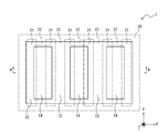
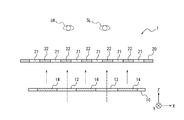
- FIG. 3 is a sectional view taken along line AA of FIG. 2.
- FIG. 3 is a diagram illustrating an example of a configuration of a light emitting panel and a shutter panel. It is a figure showing other examples of composition of a light emitting panel and a shutter panel.
- the information display system 100 includes an information display device 1 and a camera 2.
- the information display device 1 includes a light emitting panel 10, a shutter panel 20, and a controller 30.
- the information display device 1 may further include an acquisition unit 40.
- the acquisition unit 40 may be connected to the camera 2. When connected to the camera 2, the obtaining unit 40 can obtain information from the camera 2.
- the controller 30 is connected to each component of the information display device 1 and controls each component.
- the controller 30 is configured as, for example, a processor.
- Controller 30 may include one or more processors.
- the processor may include a general-purpose processor that executes a specific function by reading a specific program, and a dedicated processor specialized for a specific process.
- the dedicated processor may include an application specific integrated circuit (ASIC: Application Specific Integrated Circuit).
- the processor may include a programmable logic device (PLD: Programmable Logic Device).
- the PLD may include an FPGA (Field-Programmable ⁇ Gate ⁇ Array).
- the controller 30 may be any one of an SoC (System-on-a-Chip) in which one or a plurality of processors cooperate, and a SiP (System ⁇ In ⁇ a ⁇ Package).
- the controller 30 includes a storage unit, and may store various information, a program for operating each component of the information display device 1, and the like in the storage unit.
- the storage unit may be composed of, for example, a semiconductor memory or the like.
- the storage unit may function as a work memory of the controller 30.
- the light emitting panel 10 includes a plurality of transmissive portions 12 and a plurality of light emitting portions 14.
- the transmission unit 12 is configured to transmit light incident from the background on the other side of the light emitting panel 10 as viewed from the user.
- the transmitting unit 12 transmits light incident from the background positioned on the negative side of the Z axis toward the left eye 5L and the right eye 5R of the user positioned on the positive side of the Z axis. Is configured.
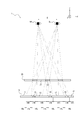
- Light incident from the background is also referred to as first light. In FIG. 3, it is assumed that the first light travels from the light emitting panel 10 to the left eye 5L and the right eye 5R of the user, as indicated by a dashed line with an arrow.
- the transmission unit 12 may have a transmittance equal to or higher than a predetermined value.
- the transmission unit 12 may include, for example, glass or resin.
- the light emitting unit 14 is configured to emit light for forming an image to the left eye 5L and the right eye 5R of the user located on the positive side of the Z axis.
- Light for forming an image is also referred to as image light or second light.
- image light or second light In FIG. 3, it is assumed that the second light travels from the light emitting panel 10 toward the left eye 5L and the right eye 5R of the user, as indicated by a broken line with an arrow.
- the light emitting unit 14 causes the second light to enter the right eye 5R and the left eye 5L of the user. The user can visually recognize the image by the second light entering the eye.
- the light emitting unit 14 may be an OLED (Organic Light Emitting Diode).
- the OLED may be a device that emits light using an organic EL (Electro-Luminescence) phenomenon.
- the light emitting unit 14 is an OLED
- the light emitting panel 10 including the transmission unit 12 is also referred to as a transparent OLED.
- the light emitting unit 14 may include a self light emitting device such as an inorganic EL.
- the shutter panel 20 is configured to overlap the light emitting panel 10 and to be located between the right eye 5R and the left eye 5L of the user and the light emitting panel 10.
- the shutter panel 20 includes a plurality of translucent regions 21 and a plurality of dimming regions 22.
- the light transmitting region 21 is operable to transmit the first light and the second light incident from the light emitting panel 10 side.
- the first light and the second light pass through the light transmitting area 21 and reach the right eye 5R and the left eye 5L of the user.
- the dimming region 22 is operable to reduce the first light and the second light incident from the light emitting panel 10 side.
- the shutter panel 20 has a plurality of elements that transition between a light-transmitting state and a dimming state.
- the shutter panel 20 may be a liquid crystal shutter.
- the liquid crystal shutter can control the light transmittance according to the applied voltage.
- the liquid crystal shutter may include a plurality of pixels, and may control the light transmittance of each pixel.
- the liquid crystal shutter can form a region having a high light transmittance or a region having a low light transmittance into an arbitrary shape.
- the light transmitting area 21 may be an area having a transmittance equal to or higher than a first predetermined value.
- the first predetermined value may be, for example, 100% or a value close to 100%.
- the dimming region 22 may be a region having a transmittance equal to or less than a second predetermined value.
- the second predetermined value may be, for example, 0% or a value close to 0%.
- the first predetermined value may be a value smaller than 50%, for example, 10% as long as a sufficient contrast with light transmitted through the darkening region 22 can be ensured.
- the second predetermined value may be a value larger than about 0%, for example, 10% as long as a sufficient contrast with light transmitted through the light transmitting region 21 can be ensured.
- a sufficient contrast ratio may be, for example, 100: 1.
- the shutter panel 20 may be a MEMS panel employing a Micro Electro Mechanical System (MEMS) shutter.
- MEMS Micro Electro Mechanical System
- the light emitting panel 10 is visually recognized by the user by the light being reduced by the user through the light transmitting area 21 and the light being reduced by the light reducing area 22. And a region that is not easily recognized or hardly recognized.
- the area visually recognized by the user through the light transmitting area 21 is also referred to as a visible area.
- An area that is not or hardly recognized by the user due to the light being reduced in the dimming area 22 is also referred to as a non-visible area.
- the viewing area includes the transmission section 12, the user can visually recognize the first light emitted from a portion of the transmission section 12 included in the viewing area.
- the viewing area includes the light emitting unit 14, the user can visually recognize the second light emitted from a portion of the light emitting unit 14 included in the viewing area.
- each of the left eye 5 ⁇ / b> L and the right eye 5 ⁇ / b> R of the user visually recognizes a part of the light emitting panel 10, but does not visually recognize the other part of the light emitting panel 10 or is difficult to visually recognize the other part.
- the area visually recognized by the left eye 5L of the user is also referred to as a left-eye visible area 16L.
- the area visually recognized by the right eye 5R of the user is also referred to as a right-eye visible area 16R.
- the left-eye viewing area 16L and the right-eye viewing area 16R can be different from each other.
- An area that is not or hardly seen by the left eye 5L of the user is also referred to as a left-eye non-viewing area 17L.
- An area that is not or hardly seen by the right eye 5R of the user is also referred to as a right-eye non-viewing area 17R.
- the left eye non-viewing area 17L and the right eye non-viewing area 17R can be different from each other.
- One of the left eye 5L and the right eye 5R of the user is also referred to as a first eye.
- the other eye is also called a second eye.
- the first eye is different from the second eye.
- the areas visually recognized by the first eye and the second eye are also referred to as a first visual recognition area and a second visual recognition area.
- the areas that are not or hardly seen by the first and second eyes are also referred to as a first non-viewing area and a second non-viewing area.
- the first viewing area is associated with the left eye viewing area 16L.
- the first eye and the second eye are arranged along the X-axis direction.
- the light-transmitting regions 21 and the light-reducing regions 22 each have a strip shape extending in the Y-axis direction, and are alternately arranged along the X-axis direction. That is, the end line of the light transmitting region 21 is a straight line or a line segment extending along the Y-axis direction.
- the direction in which the light-transmitting regions 21 and the light-reducing regions 22 are alternately aligned corresponds to the direction in which the first eye and the second eye are aligned.
- the end line of the light transmitting region 21 may extend in a direction inclined at a predetermined angle with respect to the Y-axis direction.
- the predetermined angle is an angle larger than 0 degrees and smaller than 90 degrees.
- the direction in which the end line of the translucent region 21 extends intersects the direction in which the first eye and the second eye are arranged.
- the translucent area 21 and the dimming area 22 are configured to be alternately arranged in a predetermined direction including a component in the direction in which the first and second eyes of the user are arranged.
- the first viewing region and the second viewing region do not overlap each other at least in part.
- the direction in which the end line of the translucent region 21 extends intersects the direction in which the first eye and the second eye are arranged, so that the first visual recognition region and the second visual recognition region are arranged.
- the area can be different.
- the information display device 1 allows the first light transmitted through the transmission unit 12 to reach the first eye of the user to visually recognize the background, and causes the second eye to emit the second light emitted from the light emitting unit 14. And the image can be visually recognized. By causing the light emitted from different distances to enter the first eye and the second eye, the user can focus on the light entering the first eye and the second eye, respectively. As a result, the user can visually recognize both the background and the image.
- the first viewing region and the second viewing region are entirely or mostly Overlap.
- both the first light transmitted through the transmission unit 12 and the second light emitted from the light emitting unit 14 are incident on the first eye and the second eye of the user.
- both the first light and the second light enter one eye, it is difficult for the user to focus on both of the lights at the same time. Therefore, even if both the first light and the second light are incident on one eye, it is difficult to visually recognize both the background and the image with one eye.
- the left-eye viewing area 16L and the left-eye non-viewing area 17L are separated by a boundary and are alternately arranged in the X-axis direction.
- the right-eye viewing area 16R and the right-eye non-viewing area 17R are separated by a boundary and are alternately arranged in the X-axis direction.
- the position of the boundary is determined based on the position of the end line of the light transmitting area 21, the distance between the shutter panel 20 and the user's eye, and the distance between the light emitting panel 10 and the shutter panel 20. .
- the distance between the shutter panel 20 and the user's eye is also called an observation distance, and is represented as P in FIG.
- the distance between the light emitting panel 10 and the shutter panel 20 is also called a gap, and is represented as g in FIG.
- the position of each of the left-eye viewing area 16L and the right-eye viewing area 16R is determined based on not only the observation distance (P) and the gap (g) but also the positions of the left eye 5L and the right eye 5R of the user. .
- the positional relationship between the left-eye viewing area 16L and the right-eye viewing area 16R is determined not only by the observation distance (P) and the gap (g), but also by the distance between the user's left eye 5L and right eye 5R.
- the distance between the left eye 5L and the right eye 5R of the user is also referred to as interocular distance, and is represented as E in FIG.
- the left-eye viewing area 16L When the left-eye viewing area 16L is included in the right-eye non-viewing area 17R, the left-eye viewing area 16L is visually recognized by the user's left eye 5L, but is not or hardly viewed by the user's right eye 5R.
- the right-eye viewing area 16R When the right-eye viewing area 16R is included in the left-eye non-viewing area 17L, the right-eye viewing area 16R is visually recognized by the user's right eye 5R, but is not or hardly viewed by the user's left eye 5L.
- the left-eye viewing area 16L and the right-eye viewing area 16R overlap with each other. It can be said that it does not. In the example of FIG. 4, the left-eye viewing area 16L and the right-eye viewing area 16R do not overlap with each other.
- the left-eye viewing area 16L matches the right-eye non-viewing area 17R
- the right-eye viewing area 16R matches the left-eye non-viewing area 17L.
- the left-eye viewing area 16L and the right-eye viewing area 16R are adjacent to each other.
- the left-eye viewing area 16L and the right-eye viewing area 16R match the area of the light emitting unit 14 and the area of the transmission unit 12, respectively. In this case, the user can visually recognize only the light emitting unit 14 with the left eye 5L and only see the transmission unit 12 with the right eye 5R.
- the controller 30 can control the position or shape of each of the light transmitting area 21 and the light reducing area 22 of the shutter panel 20. That is, the controller 30 can control the position or shape of the end line of the light transmitting region 21.
- the controller 30 can control the position or shape of the light transmitting region 21 or the position or shape of the end line of the light transmitting region 21 by controlling the position or shape of the light reducing region 22.
- the controller 30 can control the position or shape of each of the visible region and the non-viewable region by controlling the position or shape of each of the light-transmitting region 21 and the dimming region 22.
- the controller 30 controls the position or shape of each of the translucent region 21 and the dimming region 22 so that the left-eye viewing region 16L and the right-eye non-viewing region 17R coincide with each other, and the right-eye viewing region 16R and the left-eye The non-viewing area 17L can be matched.
- the shape and position of each of the transmissive portion 12 and the light emitting portion 14 are fixed. That is, the controller 30 cannot control the shape and position of each of the transmission unit 12 and the light emitting unit 14.
- the controller 30 may control the dimming region 22 of the shutter panel 20 based on the shape and position of each of the transmission unit 12 and the light emitting unit 14.
- the controller 30 can match the left-eye viewing area 16L and the right-eye viewing area 16R with the light-emitting unit 14 and the transmission unit 12 respectively.
- the predetermined distance in this case is also referred to as an optimal viewing distance (OVD: Optimal Viewing Distance).
- ODD Optimal Viewing Distance
- the controller 30 may not be able to match the left-eye viewing area 16L and the right-eye viewing area 16R with the light emitting unit 14 region and the transmission unit 12 region, respectively. No matter how the controller 30 controls the position or shape of each of the translucent region 21 and the dimming region 22, the visible region may not match the region of the transmissive part 12 or the light emitting part 14.
- the controller 30 may control the dimming area 22 of the shutter panel 20 so that the second light does not enter the first eye.
- the controller 30 may include the light emitting unit 14 in the right eye non-viewing area 17R so that the second light does not enter the right eye 5R.
- the first light and the second light do not simultaneously enter the first eye of the user.
- the user needs only to focus on the first light with the first eye, and the user can easily recognize the background.
- the controller 30 may control the dimming region 22 of the shutter panel 20 so that at least a part of the first light is incident on the second eye. For example, as shown in FIG.
- the controller 30 may include the transmission unit 12 and the light-emitting unit 14 in the left-eye viewing area 16L so that the first light and the second light enter the left eye 5L.
- the ratio of the light transmitting area 21 of the shutter panel 20 can be increased, and restrictions on the position or shape of the light reducing area 22 can be reduced.
- the controller 30 may control the dimming area 22 of the shutter panel 20 based on the shape and position of the light emitting unit 14 in the light emitting panel 10. That is, the controller 30 may control the position of the dimming region 22 in the shutter panel 20 based on the position where the second light is emitted from the light emitting panel 10 so that the second light does not enter the first eye. .
- the controller 30 may control an area of the shutter panel 20 where the dimming area 22 expands based on an area of the light emitting panel 10 from which the second light is emitted.
- the area occupied by the light emitting unit 14 may be equal to or less than the area occupied by the transmissive unit 12. That is, the ratio of the area occupied by the light emitting unit 14 to the entire area of the light emitting panel 10 may be 50% or less.
- the information display device 1 causes the second light emitted from the light emitting unit 14 to enter the second eye and not enter the first eye. It is easy to control the dimming region 22 of the shutter panel 20. In this case, the ratio of the area occupied by the light transmitting region 21 in the shutter panel 20 can be further increased.
- the information display device 1 can increase the amount of light transmitted through the shutter panel 20 by increasing the size of the light transmitting region 21. As a result, the information display device 1 makes it easy for the user to visually recognize the background and the image.
- the information display device 1 may increase the area of the dimming region 22 of the shutter panel 20. Accordingly, it is possible to make the second light hard to enter the first eye.
- the controller 30 may control the dimming area 22 of the shutter panel 20 based on information on the positions of the left eye 5L and the right eye 5R of the user.
- the controller 30 may use the acquisition unit 40 to acquire information on the positions of the left eye 5L and the right eye 5R of the user.
- Information regarding the position of the first eye of the user is also referred to as first position information.
- Information on the position of the user's second eye is also referred to as second position information. That is, the controller 30 may obtain the first position information and the second position information by the obtaining unit 40 and control the dimming area 22 of the shutter panel 20 based on the first position information and the second position information.
- the acquisition unit 40 is configured to acquire information on at least one of the positions of the left eye 5L and the right eye 5R of the user and output the information to the controller 30.
- the acquisition unit 40 may acquire information on the positions of the left eye 5L and the right eye 5R of the user.
- the acquisition unit 40 may acquire information on the position of the left eye 5L or the right eye 5R of the user from the camera 2.
- the camera 2 may detect the position of at least one of the left eye 5L and the right eye 5R of the user and output information on the position.
- the camera 2 may photograph a user's face and detect at least one position of the left eye 5L and the right eye 5R based on the captured image.
- the camera 2 may detect at least one position of the left eye 5L and the right eye 5R as coordinates in a three-dimensional space based on the captured image.
- the camera 2 may include a plurality of image sensors.
- the camera 2 may detect at least one position of the left eye 5L and the right eye 5R as coordinates in a three-dimensional space based on a captured image of each image sensor.
- the acquisition unit 40 may include the camera 2 or may be connected to the camera 2 provided as a separate component from the information display device 1.
- the acquisition unit 40 may include an input terminal for inputting a signal from the camera 2.
- the camera 2 may be directly connected to the input terminal.
- the camera 2 may be indirectly connected to an input terminal via a shared network.
- the acquisition unit 40 that does not include the camera 2 may include an input terminal to which a video signal is input from the camera 2.
- the acquisition unit 40 may detect at least one of the left eye 5L and the right eye 5R from the video signal input to the input terminal.
- the acquisition unit 40 may include, for example, a sensor.
- the sensor may be an ultrasonic sensor, an optical sensor, or the like.
- the acquisition unit 40 may detect the position of the user's head with a sensor and detect at least one of the left eye 5L and the right eye 5R based on the position of the head.
- the acquisition unit 40 may detect at least one position of the left eye 5L and the right eye 5R as coordinates in a three-dimensional space by one or two or more sensors.
- the acquisition unit 40 calculates the distance between the left eye 5L and the right eye 5R and the shutter panel 20 as the observation distance (P) based on the detection result of at least one position of the left eye 5L and the right eye 5R. .
- the acquisition unit 40 can calculate the difference between the coordinates of the left eye 5L and the right eye 5R in the Z-axis direction and the coordinates of the shutter panel 20 in the Z-axis direction as the observation distance (P).
- the acquisition unit 40 may calculate the interocular distance (E) based on the detection results of the positions of the left eye 5L and the right eye 5R.
- the information display device 1 may not include the acquisition unit 40.
- the controller 30 may include an input terminal that is provided outside the device and that inputs a signal from a device for detecting the position of a user's eye.
- a detection device outside the device may be connected to the input terminal.
- the detection device outside the device may use an electric signal and an optical signal as a transmission signal to the input terminal.
- the detection device outside the device may be indirectly connected to the input terminal via a shared network.
- the controller 30 controls the shutter panel 20 based on the information on the position of the user's eyes, so that the user can more easily see the background and the image simultaneously.
- the controller 30 may control the shutter panel 20 on the assumption that the user is at a predetermined position with respect to the information display device 1. In this case, the user relatively recognizes the background seen beyond the transmissive part 12 and the image formed by the light emitted from the light emitting part 14 at the same time relative to the information display device 1 so as to be easily visible. You may move.
- a device including the light emitting panel 10 having the transmission unit 12 and the light emitting unit 14 but not including the shutter panel 20 is assumed.
- the first light transmitted through the transmission unit 12 and the second light emitted from the light emitting unit 14 are both the left eye 5L and the right eye 5R of the user. Incident on the eye.
- both the first light and the second light enter one eye, it is difficult for the user to focus on both of the lights at the same time.
- the light emitting unit 14 emits light with relatively low luminance, the eye easily focuses on the background, but it is difficult to focus on the light emitting unit 14 or it is difficult to visually recognize a low luminance image.
- the information display device 1 includes the shutter panel 20 having the light transmitting area 21 and the light reducing area 22.
- the shutter panel 20 allows one of the left eye 5L and the right eye 5R of the user to visually recognize the light transmitted through the transmitting unit 12 and the other eye to visually recognize the light emitted from the light emitting unit 14. Operable. By doing so, the user can focus on the light emitting unit 14 with the other eye while focusing on the background with one eye. As a result, the user can visually recognize the background seen through the transmission unit 12 and the image related to the light emitted from the light emitting unit 14 at the same time. That is, to the user, the image appears to be superimposed on the background.
- the controller 15 can reduce the light emission of the light emitting unit 14.
- the controller 15 can reduce the visibility of the light emitting unit 14 by the first eye by reducing the light emission by the light emitting unit 14 included in the first visible region.
- descriptions such as “first” and “second” are identifiers for distinguishing the configuration.
- the numbers in the configurations can be exchanged.
- the first light can exchange the second light with the identifiers “first” and “second”.
- the exchange of identifiers takes place simultaneously.
- the configuration is distinguished.
- the identifier may be deleted.
- the configuration from which the identifier is deleted is distinguished by a code. It should not be used for interpretation of the order of the configuration or grounds for the existence of an identifier having a small number based only on the description of the identifier such as “first” and “second” in the present disclosure.
- the X axis, the Y axis, and the Z axis are provided for convenience of description, and may be interchanged with each other.
- the configuration according to the present disclosure has been described using an orthogonal coordinate system including the X axis, the Y axis, and the Z axis.
- the positional relationship between the components according to the present disclosure is not limited to the orthogonal relationship.
Landscapes
- Physics & Mathematics (AREA)
- General Physics & Mathematics (AREA)
- Engineering & Computer Science (AREA)
- Optics & Photonics (AREA)
- Signal Processing (AREA)
- Multimedia (AREA)
- Marketing (AREA)
- Accounting & Taxation (AREA)
- Theoretical Computer Science (AREA)
- Business, Economics & Management (AREA)
- Liquid Crystal (AREA)
- Devices For Indicating Variable Information By Combining Individual Elements (AREA)
- Transforming Electric Information Into Light Information (AREA)
- Testing, Inspecting, Measuring Of Stereoscopic Televisions And Televisions (AREA)
Abstract
L'invention concerne un dispositif d'affichage d'informations qui est pourvu d'un panneau d'émission de lumière, d'un panneau d'obturateur et d'un dispositif de commande. Le panneau d'émission de lumière comprend : une pluralité d'unités de transmission configurées pour transmettre une première lumière ; et une pluralité d'unités d'émission de lumière configurées pour émettre une seconde lumière. Les unités de transmission et les unités d'émission de lumière sont conçues pour être disposées en alternance le long d'une direction prescrite comprenant un élément d'une direction dans laquelle un premier œil et un second œil d'un utilisateur sont agencés. Le panneau d'obturateur est configuré pour être positionné de manière à chevaucher le panneau d'émission de lumière, et comprend une zone de gradation dans laquelle le panneau d'obturateur peut fonctionner pour réduire la première lumière et la seconde lumière. Le dispositif de commande peut commander la zone de gradation de telle sorte que la première lumière est incidente sur le premier œil et que la seconde lumière est incidente sur le second œil.
Priority Applications (4)
| Application Number | Priority Date | Filing Date | Title |
|---|---|---|---|
| EP19826486.3A EP3816974A4 (fr) | 2018-06-26 | 2019-06-21 | Dispositif et système d'affichage d'informations |
| JP2020527475A JP6924903B2 (ja) | 2018-06-26 | 2019-06-21 | 情報表示装置及び情報表示システム |
| CN201980041148.0A CN112352273B (zh) | 2018-06-26 | 2019-06-21 | 信息显示装置及信息显示系统 |
| US17/255,292 US20210165242A1 (en) | 2018-06-26 | 2019-06-21 | Information display device and information display system |
Applications Claiming Priority (2)
| Application Number | Priority Date | Filing Date | Title |
|---|---|---|---|
| JP2018-121272 | 2018-06-26 | ||
| JP2018121272 | 2018-06-26 |
Publications (1)
| Publication Number | Publication Date |
|---|---|
| WO2020004256A1 true WO2020004256A1 (fr) | 2020-01-02 |
Family
ID=68986878
Family Applications (1)
| Application Number | Title | Priority Date | Filing Date |
|---|---|---|---|
| PCT/JP2019/024703 Ceased WO2020004256A1 (fr) | 2018-06-26 | 2019-06-21 | Dispositif et système d'affichage d'informations |
Country Status (5)
| Country | Link |
|---|---|
| US (1) | US20210165242A1 (fr) |
| EP (1) | EP3816974A4 (fr) |
| JP (1) | JP6924903B2 (fr) |
| CN (1) | CN112352273B (fr) |
| WO (1) | WO2020004256A1 (fr) |
Families Citing this family (2)
| Publication number | Priority date | Publication date | Assignee | Title |
|---|---|---|---|---|
| JP6659902B1 (ja) * | 2019-08-21 | 2020-03-04 | 株式会社ドワンゴ | 表示媒体、処理装置および処理プログラム |
| AU2022202221B1 (en) * | 2022-01-21 | 2022-08-04 | Metrix Group Pty Ltd | Animated Perforated Images |
Citations (11)
| Publication number | Priority date | Publication date | Assignee | Title |
|---|---|---|---|---|
| JPH07181429A (ja) * | 1993-11-15 | 1995-07-21 | Sanyo Electric Co Ltd | 立体表示装置 |
| JP2008112060A (ja) * | 2006-10-31 | 2008-05-15 | Seiko Epson Corp | 表示装置 |
| JP2008112062A (ja) * | 2006-10-31 | 2008-05-15 | Seiko Epson Corp | 表示装置 |
| JP2011142289A (ja) * | 2010-01-05 | 2011-07-21 | Samsung Mobile Display Co Ltd | 有機発光表示装置 |
| JP2011180367A (ja) * | 2010-03-01 | 2011-09-15 | Seiko Epson Corp | 画像表示装置、表示パネル、及び視差バリア |
| JP2012506604A (ja) | 2008-10-21 | 2012-03-15 | コーニンクレッカ フィリップス エレクトロニクス エヌ ヴィ | 透明oledデバイス |
| JP2013137486A (ja) * | 2011-03-11 | 2013-07-11 | Semiconductor Energy Lab Co Ltd | 表示装置および表示装置の駆動方法 |
| JP2017044868A (ja) * | 2015-08-26 | 2017-03-02 | 大日本印刷株式会社 | シースルー型のled表示装置 |
| US20170194390A1 (en) * | 2014-06-30 | 2017-07-06 | Lg Display Co., Ltd. | Transparent organic light-emitting display device |
| JP2018120191A (ja) * | 2017-01-27 | 2018-08-02 | 公立大学法人大阪市立大学 | 3次元表示システム、ヘッドアップディスプレイシステム、及び移動体 |
| US20180301096A1 (en) * | 2016-08-19 | 2018-10-18 | Korea Advanced Institute Of Science And Technology | Display apparatus using blind panel |
Family Cites Families (9)
| Publication number | Priority date | Publication date | Assignee | Title |
|---|---|---|---|---|
| KR20110109565A (ko) * | 2010-03-31 | 2011-10-06 | 삼성전자주식회사 | 백라이트 유닛, 이를 구비한 3d 디스플레이 및 3d 영상 형성 방법 |
| KR101652401B1 (ko) * | 2010-09-07 | 2016-08-31 | 삼성전자주식회사 | 입체 영상 디스플레이 장치 및 입체 영상 표시 방법 |
| KR20120034581A (ko) * | 2010-10-01 | 2012-04-12 | 삼성전자주식회사 | 배리어를 이용하는 3d 디스플레이 장치 및 그 구동 방법 |
| US9035860B2 (en) * | 2011-02-16 | 2015-05-19 | Semiconductor Energy Laboratory Co., Ltd. | Display device |
| JP2015001614A (ja) * | 2013-06-14 | 2015-01-05 | 株式会社ジャパンディスプレイ | 表示装置 |
| CN105093546A (zh) * | 2015-08-20 | 2015-11-25 | 京东方科技集团股份有限公司 | 3d显示装置及其控制方法 |
| CN105093548B (zh) * | 2015-08-20 | 2018-10-23 | 京东方科技集团股份有限公司 | 3d显示装置的控制方法、控制装置及3d显示装置 |
| CN106791796B (zh) * | 2017-01-11 | 2019-02-01 | 京东方科技集团股份有限公司 | 显示面板及其驱动方法和制作方法、显示装置 |
| CN107959846B (zh) * | 2017-12-06 | 2019-12-03 | 苏州佳世达电通有限公司 | 影像显示设备及影像显示方法 |
-
2019
- 2019-06-21 US US17/255,292 patent/US20210165242A1/en not_active Abandoned
- 2019-06-21 EP EP19826486.3A patent/EP3816974A4/fr not_active Withdrawn
- 2019-06-21 WO PCT/JP2019/024703 patent/WO2020004256A1/fr not_active Ceased
- 2019-06-21 CN CN201980041148.0A patent/CN112352273B/zh active Active
- 2019-06-21 JP JP2020527475A patent/JP6924903B2/ja active Active
Patent Citations (11)
| Publication number | Priority date | Publication date | Assignee | Title |
|---|---|---|---|---|
| JPH07181429A (ja) * | 1993-11-15 | 1995-07-21 | Sanyo Electric Co Ltd | 立体表示装置 |
| JP2008112060A (ja) * | 2006-10-31 | 2008-05-15 | Seiko Epson Corp | 表示装置 |
| JP2008112062A (ja) * | 2006-10-31 | 2008-05-15 | Seiko Epson Corp | 表示装置 |
| JP2012506604A (ja) | 2008-10-21 | 2012-03-15 | コーニンクレッカ フィリップス エレクトロニクス エヌ ヴィ | 透明oledデバイス |
| JP2011142289A (ja) * | 2010-01-05 | 2011-07-21 | Samsung Mobile Display Co Ltd | 有機発光表示装置 |
| JP2011180367A (ja) * | 2010-03-01 | 2011-09-15 | Seiko Epson Corp | 画像表示装置、表示パネル、及び視差バリア |
| JP2013137486A (ja) * | 2011-03-11 | 2013-07-11 | Semiconductor Energy Lab Co Ltd | 表示装置および表示装置の駆動方法 |
| US20170194390A1 (en) * | 2014-06-30 | 2017-07-06 | Lg Display Co., Ltd. | Transparent organic light-emitting display device |
| JP2017044868A (ja) * | 2015-08-26 | 2017-03-02 | 大日本印刷株式会社 | シースルー型のled表示装置 |
| US20180301096A1 (en) * | 2016-08-19 | 2018-10-18 | Korea Advanced Institute Of Science And Technology | Display apparatus using blind panel |
| JP2018120191A (ja) * | 2017-01-27 | 2018-08-02 | 公立大学法人大阪市立大学 | 3次元表示システム、ヘッドアップディスプレイシステム、及び移動体 |
Non-Patent Citations (1)
| Title |
|---|
| See also references of EP3816974A4 |
Also Published As
| Publication number | Publication date |
|---|---|
| CN112352273B (zh) | 2023-07-14 |
| JP6924903B2 (ja) | 2021-08-25 |
| CN112352273A (zh) | 2021-02-09 |
| JPWO2020004256A1 (ja) | 2021-08-02 |
| EP3816974A1 (fr) | 2021-05-05 |
| EP3816974A4 (fr) | 2022-03-30 |
| US20210165242A1 (en) | 2021-06-03 |
Similar Documents
| Publication | Publication Date | Title |
|---|---|---|
| US10061992B2 (en) | Image display system | |
| CN106605172B (zh) | 显示装置、用于驱动显示装置的方法以及电子设备 | |
| CN110073659A (zh) | 光源装置、显示器装置、移动体、三维投影装置、三维投影系统、图像投影装置以及图像显示装置 | |
| JP2015152746A (ja) | 表示装置 | |
| CN110832382B (zh) | 图像投影装置和移动体 | |
| US20100225564A1 (en) | Image display device | |
| US20130044138A1 (en) | Image position adjustment device | |
| JP2016055782A (ja) | 表示機能付きミラー装置および表示切替方法 | |
| JP6252203B2 (ja) | 表示装置 | |
| CN113039785A (zh) | 三维显示装置、三维显示系统、平视显示器以及移动体 | |
| JP6384996B2 (ja) | 表示装置 | |
| JP2020017935A (ja) | 表示装置、表示システムおよび移動体 | |
| JP7337147B2 (ja) | 立体虚像表示モジュール、立体虚像表示システム、および移動体 | |
| CN112352273B (zh) | 信息显示装置及信息显示系统 | |
| WO2022230824A1 (fr) | Dispositif d'affichage d'image et procédé d'affichage d'image | |
| CN113614619A (zh) | 图像显示模块、图像显示系统、移动体、图像显示方法以及图像显示程序 | |
| CN112888990B (zh) | 图像显示装置、图像显示系统以及移动体 | |
| JP6697747B2 (ja) | 表示システム、電子ミラーシステム及び移動体 | |
| JP2018151557A (ja) | 表示方法および表示装置 | |
| JP7188888B2 (ja) | 画像表示装置、ヘッドアップディスプレイシステム、および移動体 | |
| CN116888958A (zh) | 图像显示装置 | |
| JP2017084136A (ja) | ジェスチャ入力装置 | |
| JP7642400B2 (ja) | 撮像装置および3次元表示装置 | |
| EP4145213A1 (fr) | Système d'affichage d'image | |
| CN117321665A (zh) | 非接触操作装置 |
Legal Events
| Date | Code | Title | Description |
|---|---|---|---|
| 121 | Ep: the epo has been informed by wipo that ep was designated in this application |
Ref document number: 19826486 Country of ref document: EP Kind code of ref document: A1 |
|
| ENP | Entry into the national phase |
Ref document number: 2020527475 Country of ref document: JP Kind code of ref document: A |
|
| NENP | Non-entry into the national phase |
Ref country code: DE |
|
| ENP | Entry into the national phase |
Ref document number: 2019826486 Country of ref document: EP Effective date: 20210126 |