WO2020004276A1 - 画像表示装置、画像表示システム、ヘッドアップディスプレイ、移動体および画像表示方法 - Google Patents
画像表示装置、画像表示システム、ヘッドアップディスプレイ、移動体および画像表示方法 Download PDFInfo
- Publication number
- WO2020004276A1 WO2020004276A1 PCT/JP2019/024778 JP2019024778W WO2020004276A1 WO 2020004276 A1 WO2020004276 A1 WO 2020004276A1 JP 2019024778 W JP2019024778 W JP 2019024778W WO 2020004276 A1 WO2020004276 A1 WO 2020004276A1
- Authority
- WO
- WIPO (PCT)
- Prior art keywords
- sub
- image
- pixels
- eye
- pixel
- Prior art date
- Legal status (The legal status is an assumption and is not a legal conclusion. Google has not performed a legal analysis and makes no representation as to the accuracy of the status listed.)
- Ceased
Links
Images









Classifications
-
- G—PHYSICS
- G02—OPTICS
- G02B—OPTICAL ELEMENTS, SYSTEMS OR APPARATUS
- G02B27/00—Optical systems or apparatus not provided for by any of the groups G02B1/00 - G02B26/00, G02B30/00
- G02B27/01—Head-up displays
- G02B27/0179—Display position adjusting means not related to the information to be displayed
-
- H—ELECTRICITY
- H04—ELECTRIC COMMUNICATION TECHNIQUE
- H04N—PICTORIAL COMMUNICATION, e.g. TELEVISION
- H04N13/00—Stereoscopic video systems; Multi-view video systems; Details thereof
- H04N13/30—Image reproducers
- H04N13/366—Image reproducers using viewer tracking
-
- B—PERFORMING OPERATIONS; TRANSPORTING
- B60—VEHICLES IN GENERAL
- B60K—ARRANGEMENT OR MOUNTING OF PROPULSION UNITS OR OF TRANSMISSIONS IN VEHICLES; ARRANGEMENT OR MOUNTING OF PLURAL DIVERSE PRIME-MOVERS IN VEHICLES; AUXILIARY DRIVES FOR VEHICLES; INSTRUMENTATION OR DASHBOARDS FOR VEHICLES; ARRANGEMENTS IN CONNECTION WITH COOLING, AIR INTAKE, GAS EXHAUST OR FUEL SUPPLY OF PROPULSION UNITS IN VEHICLES
- B60K35/00—Instruments specially adapted for vehicles; Arrangement of instruments in or on vehicles
- B60K35/20—Output arrangements, i.e. from vehicle to user, associated with vehicle functions or specially adapted therefor
- B60K35/21—Output arrangements, i.e. from vehicle to user, associated with vehicle functions or specially adapted therefor using visual output, e.g. blinking lights or matrix displays
- B60K35/211—Output arrangements, i.e. from vehicle to user, associated with vehicle functions or specially adapted therefor using visual output, e.g. blinking lights or matrix displays producing three-dimensional [3D] effects, e.g. stereoscopic images
-
- B—PERFORMING OPERATIONS; TRANSPORTING
- B60—VEHICLES IN GENERAL
- B60K—ARRANGEMENT OR MOUNTING OF PROPULSION UNITS OR OF TRANSMISSIONS IN VEHICLES; ARRANGEMENT OR MOUNTING OF PLURAL DIVERSE PRIME-MOVERS IN VEHICLES; AUXILIARY DRIVES FOR VEHICLES; INSTRUMENTATION OR DASHBOARDS FOR VEHICLES; ARRANGEMENTS IN CONNECTION WITH COOLING, AIR INTAKE, GAS EXHAUST OR FUEL SUPPLY OF PROPULSION UNITS IN VEHICLES
- B60K35/00—Instruments specially adapted for vehicles; Arrangement of instruments in or on vehicles
- B60K35/20—Output arrangements, i.e. from vehicle to user, associated with vehicle functions or specially adapted therefor
- B60K35/21—Output arrangements, i.e. from vehicle to user, associated with vehicle functions or specially adapted therefor using visual output, e.g. blinking lights or matrix displays
- B60K35/23—Head-up displays [HUD]
- B60K35/235—Head-up displays [HUD] with means for detecting the driver's gaze direction or eye points
-
- G—PHYSICS
- G02—OPTICS
- G02B—OPTICAL ELEMENTS, SYSTEMS OR APPARATUS
- G02B27/00—Optical systems or apparatus not provided for by any of the groups G02B1/00 - G02B26/00, G02B30/00
- G02B27/01—Head-up displays
- G02B27/0101—Head-up displays characterised by optical features
-
- G—PHYSICS
- G02—OPTICS
- G02B—OPTICAL ELEMENTS, SYSTEMS OR APPARATUS
- G02B30/00—Optical systems or apparatus for producing three-dimensional [3D] effects, e.g. stereoscopic images
- G02B30/20—Optical systems or apparatus for producing three-dimensional [3D] effects, e.g. stereoscopic images by providing first and second parallax images to an observer's left and right eyes
- G02B30/26—Optical systems or apparatus for producing three-dimensional [3D] effects, e.g. stereoscopic images by providing first and second parallax images to an observer's left and right eyes of the autostereoscopic type
- G02B30/30—Optical systems or apparatus for producing three-dimensional [3D] effects, e.g. stereoscopic images by providing first and second parallax images to an observer's left and right eyes of the autostereoscopic type involving parallax barriers
-
- H—ELECTRICITY
- H04—ELECTRIC COMMUNICATION TECHNIQUE
- H04N—PICTORIAL COMMUNICATION, e.g. TELEVISION
- H04N13/00—Stereoscopic video systems; Multi-view video systems; Details thereof
- H04N13/30—Image reproducers
- H04N13/302—Image reproducers for viewing without the aid of special glasses, i.e. using autostereoscopic displays
- H04N13/31—Image reproducers for viewing without the aid of special glasses, i.e. using autostereoscopic displays using parallax barriers
-
- H—ELECTRICITY
- H04—ELECTRIC COMMUNICATION TECHNIQUE
- H04N—PICTORIAL COMMUNICATION, e.g. TELEVISION
- H04N13/00—Stereoscopic video systems; Multi-view video systems; Details thereof
- H04N13/30—Image reproducers
- H04N13/302—Image reproducers for viewing without the aid of special glasses, i.e. using autostereoscopic displays
- H04N13/317—Image reproducers for viewing without the aid of special glasses, i.e. using autostereoscopic displays using slanted parallax optics
-
- H—ELECTRICITY
- H04—ELECTRIC COMMUNICATION TECHNIQUE
- H04N—PICTORIAL COMMUNICATION, e.g. TELEVISION
- H04N13/00—Stereoscopic video systems; Multi-view video systems; Details thereof
- H04N13/30—Image reproducers
- H04N13/324—Colour aspects
-
- H—ELECTRICITY
- H04—ELECTRIC COMMUNICATION TECHNIQUE
- H04N—PICTORIAL COMMUNICATION, e.g. TELEVISION
- H04N13/00—Stereoscopic video systems; Multi-view video systems; Details thereof
- H04N13/30—Image reproducers
- H04N13/398—Synchronisation thereof; Control thereof
-
- B—PERFORMING OPERATIONS; TRANSPORTING
- B60—VEHICLES IN GENERAL
- B60K—ARRANGEMENT OR MOUNTING OF PROPULSION UNITS OR OF TRANSMISSIONS IN VEHICLES; ARRANGEMENT OR MOUNTING OF PLURAL DIVERSE PRIME-MOVERS IN VEHICLES; AUXILIARY DRIVES FOR VEHICLES; INSTRUMENTATION OR DASHBOARDS FOR VEHICLES; ARRANGEMENTS IN CONNECTION WITH COOLING, AIR INTAKE, GAS EXHAUST OR FUEL SUPPLY OF PROPULSION UNITS IN VEHICLES
- B60K35/00—Instruments specially adapted for vehicles; Arrangement of instruments in or on vehicles
- B60K35/10—Input arrangements, i.e. from user to vehicle, associated with vehicle functions or specially adapted therefor
-
- G—PHYSICS
- G02—OPTICS
- G02B—OPTICAL ELEMENTS, SYSTEMS OR APPARATUS
- G02B27/00—Optical systems or apparatus not provided for by any of the groups G02B1/00 - G02B26/00, G02B30/00
- G02B27/01—Head-up displays
- G02B27/0101—Head-up displays characterised by optical features
- G02B2027/0132—Head-up displays characterised by optical features comprising binocular systems
- G02B2027/0134—Head-up displays characterised by optical features comprising binocular systems of stereoscopic type
-
- G—PHYSICS
- G02—OPTICS
- G02B—OPTICAL ELEMENTS, SYSTEMS OR APPARATUS
- G02B27/00—Optical systems or apparatus not provided for by any of the groups G02B1/00 - G02B26/00, G02B30/00
- G02B27/01—Head-up displays
- G02B27/0179—Display position adjusting means not related to the information to be displayed
- G02B2027/0187—Display position adjusting means not related to the information to be displayed slaved to motion of at least a part of the body of the user, e.g. head, eye
-
- G—PHYSICS
- G09—EDUCATION; CRYPTOGRAPHY; DISPLAY; ADVERTISING; SEALS
- G09G—ARRANGEMENTS OR CIRCUITS FOR CONTROL OF INDICATING DEVICES USING STATIC MEANS TO PRESENT VARIABLE INFORMATION
- G09G3/00—Control arrangements or circuits, of interest only in connection with visual indicators other than cathode-ray tubes
- G09G3/001—Control arrangements or circuits, of interest only in connection with visual indicators other than cathode-ray tubes using specific devices not provided for in groups G09G3/02 - G09G3/36, e.g. using an intermediate record carrier such as a film slide; Projection systems; Display of non-alphanumerical information, solely or in combination with alphanumerical information, e.g. digital display on projected diapositive as background
- G09G3/003—Control arrangements or circuits, of interest only in connection with visual indicators other than cathode-ray tubes using specific devices not provided for in groups G09G3/02 - G09G3/36, e.g. using an intermediate record carrier such as a film slide; Projection systems; Display of non-alphanumerical information, solely or in combination with alphanumerical information, e.g. digital display on projected diapositive as background to produce spatial visual effects
Definitions
- the present disclosure relates to an image display device, an image display system, a head-up display, a moving object, and an image display method.
- a parallax image is made to reach left and right eyes to display a three-dimensional image.
- a display device has been proposed (for example, see Patent Document 1). The fact that the parallax barrier extends in the diagonal direction contributes to reducing the occurrence of moire and the like.
- the lengths of subpixels in the parallax direction of the left and right eyes are equal.
- the image display device includes a display panel, an optical element, an acquisition unit, and a controller.
- the display panel includes a plurality of sub-pixels arranged in a grid along a first direction corresponding to the parallax direction of the user and a second direction intersecting the first direction.
- the optical element is configured to define a light beam direction of an image displayed on the display panel.
- the acquisition unit is configured to acquire a first position of a first eye of the user and a second position of a second eye different from the first eye.
- the controller is configured to be able to switch a display position for displaying the first image and the second image for each sub-pixel included in the plurality of sub-pixels, based on the first position and the second position.
- the first image is an image visually recognized by the first eye of the user.
- the second image is an image visually recognized by the second eye of the user.
- the plurality of sub-pixels include a plurality of first sub-pixels configured to emit light of a first color and a plurality of second sub-pixels configured to emit light of a second color different from the first color. And wherein the first sub-pixel and the second sub-pixel have different lengths along the first direction.
- the controller is configured to control a plurality of the sub-pixels including a plurality of the first sub-pixels and a plurality of the second sub-pixels as a group. The controller, when changing the image displayed by one of the first sub-pixels belonging to the group from the first image to the second image, displays the other one of the first sub-pixels belonging to the group.
- the first image is configured to be changed from the second image to the first image.
- the image display system includes a display panel, an optical element, a detection device, and a controller.
- the display panel includes a plurality of sub-pixels arranged in a grid along a first direction corresponding to the parallax direction of the user and a second direction intersecting the first direction.
- the optical element is configured to define a light beam direction of an image displayed on the display panel.
- the detection device is configured to be able to detect a first position of a first eye of the user and a second position of a second eye different from the first eye.
- the controller switches a display position for displaying a first image and a second image for each sub-pixel included in the plurality of sub-pixels based on the first position and the second position detected by the detection device.
- the first image is an image visually recognized by the first eye of the user.
- the second image is an image visually recognized by the second eye of the user.
- the plurality of sub-pixels include a plurality of first sub-pixels configured to emit light of a first color and a plurality of second sub-pixels configured to emit light of a second color different from the first color. And wherein the first sub-pixel and the second sub-pixel have different lengths along the first direction.
- the controller is configured to control a plurality of the sub-pixels including a plurality of the first sub-pixels and a plurality of the second sub-pixels as a group. The controller, when changing the image displayed by one of the first sub-pixels belonging to the group from the first image to the second image, displays the other one of the first sub-pixels belonging to the group.
- the first image is configured to be changed from the second image to the first image.
- a head-up display includes a display panel, an optical element, a detection device, a controller, and an optical system.
- the display panel includes a plurality of sub-pixels arranged in a grid along a first direction corresponding to the parallax direction of the user and a second direction intersecting the first direction.
- the optical element is configured to define a light beam direction of an image displayed on the display panel.
- the detection device is configured to be able to detect a first position of a first eye of the user and a second position of a second eye different from the first eye.
- the controller switches a display position for displaying a first image and a second image for each sub-pixel included in the plurality of sub-pixels based on the first position and the second position detected by the detection device. It is configured to be possible.
- the first image is an image visually recognized by the first eye of the user.
- the second image is an image visually recognized by the second eye of the user.
- the optical system is configured to project a virtual image of the display panel, which is arranged on a side of the display panel and the optical element where the user's eyes are arranged.
- the plurality of sub-pixels include a plurality of first sub-pixels configured to emit light of a first color and a plurality of second sub-pixels configured to emit light of a second color different from the first color.
- the controller is configured to control a plurality of the sub-pixels including a plurality of the first sub-pixels and a plurality of the second sub-pixels as a group.
- the controller when changing the image displayed by one of the first sub-pixels belonging to the group from the first image to the second image, displays the other one of the first sub-pixels belonging to the group.
- the first image is configured to be changed from the second image to the first image.
- a moving object includes a head-up display.
- the head-up display includes a display panel, an optical element, a detection device, a controller, and an optical system.
- the display panel includes a plurality of sub-pixels arranged in a grid along a first direction corresponding to the parallax direction of the user and a second direction intersecting the first direction.
- the optical element is configured to define a light beam direction of an image displayed on the display panel.
- the detection device is configured to detect a first position of a first eye of the user and a second position of a second eye different from the first eye.
- the controller switches a display position for displaying a first image and a second image for each sub-pixel included in the plurality of sub-pixels based on the first position and the second position detected by the detection device. It is configured to be possible.
- the first image is an image visually recognized by the first eye of the user.
- the second image is an image visually recognized by the second eye of the user.
- the optical system is configured to project a virtual image of the display panel, which is arranged on a side of the display panel and the optical element where the user's eyes are arranged.
- the plurality of sub-pixels include a plurality of first sub-pixels configured to emit light of a first color and a plurality of second sub-pixels configured to emit light of a second color different from the first color.
- the controller is configured to control a plurality of the sub-pixels including a plurality of the first sub-pixels and a plurality of the second sub-pixels as a group.
- the controller when changing the image displayed by one of the first sub-pixels belonging to the group from the first image to the second image, displays the other one of the first sub-pixels belonging to the group.
- the first image is configured to be changed from the second image to the first image.
- the image display method includes acquiring the first position of the first eye of the user and the second position of the second eye different from the first eye by the acquisition unit.
- the image display method includes displaying a first image or a second image on each of a plurality of sub-pixels based on the first position and the second position by a controller.
- the plurality of sub-pixels are arranged in a grid along a first direction corresponding to a parallax direction of a user included in the display panel and a second direction intersecting the first direction.
- the image display method includes causing the first image to reach the first eye of the user and causing the second image to reach the second eye of the user by an optical element.
- the plurality of sub-pixels include a plurality of first sub-pixels configured to emit light of a first color and a plurality of second sub-pixels configured to emit light of a second color different from the first color. And wherein the first sub-pixel and the second sub-pixel have different lengths along the first direction.
- the controller is configured to control a plurality of the sub-pixels including a plurality of the first sub-pixels and a plurality of the second sub-pixels as a group.
- the controller displays another one of the first sub-pixels belonging to the group when changing the image displayed by one of the first sub-pixels belonging to the group from the first image to the second image. It is configured to change an image from the second image to the first image.
- FIG. 1 is a schematic configuration diagram of an image display device according to one embodiment.
- FIG. 2 is a diagram illustrating an example of an arrangement of sub-pixels on a display surface of a display panel.
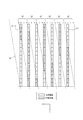
- FIG. 3 is a diagram illustrating a configuration example of the parallax barrier.
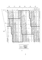
- FIG. 4 is a diagram illustrating a first example of a group of sub-pixels on a display panel.
- FIG. 5 is a diagram illustrating switching of the display area in the group of FIG.
- FIG. 6 is a diagram illustrating switching of the display area in the group of FIG.
- FIG. 7 is a diagram illustrating switching of the display area in the group of FIG.
- FIG. 8 is a diagram illustrating switching of the display area in the group of FIG. FIG.
- FIG. 9 is a diagram illustrating switching of the display area in the group of FIG.
- FIG. 10 is a diagram illustrating switching of the display area in the group of FIG.
- FIG. 11 is a diagram illustrating switching of the display area in the group of FIG.
- FIG. 12 is a diagram illustrating switching of the display area in the group of FIG.
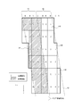
- FIG. 13 is a diagram for explaining a method of determining the switching timing of the R pixel.
- FIG. 14 is a diagram illustrating a method of determining a barrier tilt angle and a barrier pitch, and sub-pixels included in one group.
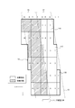
- FIG. 15 is a diagram illustrating a second example of a group of sub-pixels on the display panel.
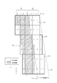
- FIG. 16 is a diagram illustrating a third example of a group of sub-pixels on the display panel.
- FIG. 17 is a schematic configuration diagram of an image display device when the optical element is a lenticular lens.
- FIG. 18 is a schematic configuration diagram of a head-up display (HUD) according to one embodiment.
- FIG. 19 is a diagram showing an example of a vehicle equipped with the HUD shown in FIG.
- a conventional image display device that performs three-dimensional display, a plurality of sub-pixels constituting one pixel have the same length in the horizontal direction.
- the image display device may want to change the area of the sub-pixel for each color. For example, the area of the G (green) sub-pixel having high visibility is made larger than the area of the R (red) and B (blue) sub-pixels to improve the luminous transmittance of the display panel of the image display device. You may want to do that.
- the luminosity is a quantity representing the brightness perceived visually.
- conventionally there has been no method for controlling the images reaching the left and right eyes when the lengths of the sub-pixels in the horizontal direction are different.
- the width of the sub-pixels in the horizontal direction is different, if the control is performed in the same manner as when a display panel having sub-pixels having the same horizontal length is used, the cross-position due to the horizontal position shift of the sub-pixels causes Talk occurs. If the width of the aperture of the parallax barrier is reduced to reduce the crosstalk, the aperture ratio decreases, the visibility decreases, and the image becomes dark.
- An image display device, an image display system, and a head-up display according to the present disclosure described below can appropriately display a three-dimensional image without lowering the brightness of an image when subpixels have different parallax lengths. Can be.
- An image display system 1 according to one of a plurality of embodiments of the present disclosure includes a detection device 2 and an image display device 3, as shown in FIG.
- FIG. 1 shows an image display system 1 viewed from above a user who observes an image with the image display device 3.
- the detection device 2 is configured to detect the position of the left eye (first position) and the position of the right eye (second position) of the user and output the detected position to the image display device 3.
- the detection device 2 may include, for example, a camera.
- the detection device 2 may be configured to be able to photograph a user's face with a camera.
- the detection device 2 may be configured to detect at least one of the left eye position and the right eye position from an image captured by the camera.
- the detection device 2 may be configured to detect at least one position of the left eye and the right eye as coordinates in a three-dimensional space from an image captured by one camera.
- the detection device 2 may be configured to detect at least one position of the left eye and the right eye as coordinates in a three-dimensional space from images captured by two or more cameras.
- the detection device 2 does not have a camera, and may be connected to a camera outside the device.
- the detecting device 2 may include an input terminal for inputting a signal from a camera outside the device.
- a camera outside the device may be directly connected to the input terminal.
- a camera outside the device may be indirectly connected to an input terminal via a network.
- the detection device 2 without a camera may include an input terminal to which the camera inputs a video signal.
- the detection device 2 without a camera may be configured to detect at least one of the left eye position and the right eye position from the video signal input to the input terminal.
- the detection device 2 may include, for example, a sensor.
- the sensor may be an ultrasonic sensor or an optical sensor or the like.
- the detection device 2 may be configured to detect the position of the user's head with a sensor and detect at least one of the left eye and the right eye based on the position of the head.
- the detection device 2 may be configured to detect the position of at least one of the left eye and the right eye as coordinates in a three-dimensional space by one or two or more sensors.
- the detection device 2 When detecting the position of one of the left eye and the right eye, the detection device 2 is configured to estimate the position of the other eye from information on the interocular distance of the user or information on general interocular distance. May be. When the detection device 2 detects the position of one eye and estimates the position of the other eye, it is assumed that the positions of the left eye and the right eye have been detected.
- the image display device 3 includes an irradiator 4, a display panel 5 as a display device, a parallax barrier 6 as an optical element, a controller 7, and an acquisition unit 8.
- the irradiator 4 is arranged on one surface side of the display panel 5 and is configured to irradiate the display panel 5 in a planar manner.
- the irradiator 4 is arranged on the side opposite to the user when viewed from the display panel 5.
- the irradiator 4 may be configured to include a light source, a light guide plate, a diffusion plate, a diffusion sheet, and the like.
- the irradiator 4 is configured to emit irradiation light by a light source and to make the irradiation light uniform in the surface direction of the display panel 5 by a light guide plate, a diffusion plate, a diffusion sheet, or the like.
- the irradiator 4 is configured to emit uniform light toward the display panel 5.
- the display panel 5 may employ a display panel such as a transmissive liquid crystal display panel.
- a display panel such as a transmissive liquid crystal display panel.
- an area of the display panel 5 where an actual image is displayed is called an active area 51.
- the display panel 5 is configured to display various images in the active area 51.
- the active area 51 of the display panel 5 in a space visually perceived by the user is referred to as a display surface 71.
- the display surface 71 It matches the position of the active area 51 of the display panel 5.
- the display surface 71 matches the position of the virtual image of the active area 51 of the display panel 5.
- the user visually captures the active area 51 on the display surface 71 in a space where the display panel 5 does not exist.
- the active area 51 of the display panel 5 includes a plurality of sub-pixels 11 arranged in a lattice along a first direction (x direction) and a second direction (y direction) intersecting the first direction.
- the second direction may be a direction substantially orthogonal to the first direction.
- the display surface 71 coincides with the active area 51.
- the first direction corresponds to a parallax direction that provides parallax to both eyes of the user.
- the first direction can be the horizontal direction viewed from the user.
- the second direction may be a vertical direction viewed from the user.
- the first direction will be described as the x direction and the second direction will be described as the y direction.
- the x direction is shown as a direction from right to left.
- the y direction is shown as a direction from top to bottom.
- a direction orthogonal to the x direction and the y direction and facing the user's eye is defined as a z direction.
- the sub-pixel 11 is longer in the y direction than in the x direction.
- Each sub-pixel 11 corresponds to one of R (red (first color)), G (green (second color)), and B (blue).
- the sub-pixel 11 configured to emit light of each color of R, G, and B will be referred to as a red sub-pixel 11R (first sub-pixel), a green sub-pixel 11G (second sub-pixel), and a blue sub-pixel 11B.
- the ratio of the first length, the second length, and the third length is set to 1: 2: 1.
- the predetermined number of sub-pixels 11 can form a pixel 12.
- the three sub-pixels 11 of the red sub-pixel 11R, the green sub-pixel 11G, and the blue sub-pixel 11B can constitute one pixel 12 as a set. In FIG. 2, for the sake of explanation, some pixels are highlighted by bold lines.
- One pixel 12 can be called one pixel.
- the length of one pixel in the x direction and the length in the y direction can be set to 1: 1 but is not limited thereto.
- the x direction is, for example, a direction in which a plurality of sub-pixels 11 constituting one pixel 12 are arranged.
- the arrangement of the sub-pixels 11 in the x direction is appropriately referred to as “row”.
- the y direction is, for example, a direction in which sub-pixels 11 of the same color are arranged.
- the arrangement of the sub-pixels 11 in the y direction is appropriately referred to as a “column”.
- R, G, and B displayed at the top for the sake of description indicate the colors of the sub-pixels 11 in each column.
- the display panel 5 is not limited to a transmissive display panel, and other display panels such as a self-luminous display panel can be used.
- the transmissive display panel includes a MEMS (Micro Electro Mechanical Systems) shutter type display panel in addition to the liquid crystal panel.
- Self-luminous display panels include organic EL (electro-luminescence) and inorganic EL display panels. When a self-luminous display panel is used as the display panel 5, the irradiator 4 becomes unnecessary.
- the parallax barrier 6 is an optical element configured to regulate the light beam direction of image light emitted from each sub-pixel 11 of the display panel 5.
- the parallax barrier 6 has, for example, a plurality of dimming regions 61 (optical elements) and a plurality of translucent regions 62, as shown in FIG.
- the plurality of light-reducing regions 61 and the plurality of light-transmitting regions 62 may have a band shape (slit shape) extending in a predetermined direction.
- the dimming region 61 and the light transmitting region 62 of the parallax barrier 6 are arranged to face the display panel 5.
- the plurality of light reducing regions 61 and the plurality of light transmitting regions 62 can be alternately arranged along the x direction.
- the plurality of dimming regions 61 have widths substantially equal to each other and are periodically arranged in the x direction.
- the plurality of translucent regions 62 have a width substantially equal to each other and are periodically arranged in the x direction.
- the width of the light transmitting region 62 in the x direction can be equal to or smaller than the width of the light reducing region 61 in the x direction. In the following description, it is assumed that the width of the light transmitting region 62 in the x direction is equal to the width of the light reducing region 61 in the x direction. In this case, the barrier aperture ratio of the parallax barrier 6 is 50%.
- the barrier aperture ratio is the width of the parallax barrier 6 in the x direction (that is, the sum of the width of the dimming region 61 in the x direction and the width of the translucent region 62 in the x direction). Is the ratio of If the barrier aperture ratio is narrow, the image becomes dark.
- the image light emitted from the sub-pixel 11 defines a range that can be visually recognized by the left eye and the right eye by the parallax barrier 6.
- the parallax barrier 6 can be located on the opposite side of the illuminator 4 with respect to the display panel 5, as shown in FIG. In another embodiment, the parallax barrier 6 can be located on the illuminator 4 side of the display panel 5.
- the light transmitting region 62 is a portion that transmits light incident on the parallax barrier 6.
- the light transmitting region 62 may transmit light with a transmittance equal to or higher than a first predetermined value.
- the first predetermined value may be, for example, approximately 100%, or may be a value less than 100%. If the image light emitted from the active area 51 is within a range in which the image light can be visually recognized well, the first predetermined value may be a value of 100% or less, for example, 80% or 50%.
- the dimming region 61 is a portion that diminishes light incident on the parallax barrier 6 and hardly transmits the light.
- the dimming region 61 significantly reduces the rate at which the image light emitted from the image displayed in the active area 51 of the display panel 5 reaches the user's eyes, or effectively blocks the light. Be composed.
- the dimming region 61 may block light with a transmittance equal to or less than a second predetermined value.
- the second predetermined value may be, for example, approximately 0%, greater than 0%, and a value close to 0%, such as 0.5%, 1%, or 3%.
- the first predetermined value may be several times or more, for example, 10 times or more, or 100 times or more larger than the second predetermined value.
- the light transmitting regions 62 and the light reducing regions 61 are alternately arranged in a direction along the xy plane.
- a line indicating the boundary between the light-reducing region 61 and the light-transmitting region 62 extends in a direction inclined at a predetermined angle ⁇ with respect to the y direction.
- the line indicating the boundary between the light reduction region 61 and the light transmission region 62 is also referred to as the boundary line between the light reduction region 61 and the light transmission region 62.
- the predetermined angle ⁇ is also called a barrier inclination angle.
- the barrier inclination angle ⁇ may be an angle larger than 0 degrees and smaller than 90 degrees.
- the parallax barrier 6 may be formed of a film or a plate-like member having a transmittance smaller than the second predetermined value.
- the dimming region 61 is configured by the film or the plate-like member.
- the light transmitting region 62 is configured by an opening provided in a film or a plate-like member.
- the film may be made of a resin or may be made of another material.
- the plate member may be made of resin, metal, or the like, or may be made of another material.
- the parallax barrier 6 is not limited to a film or a plate-shaped member, and may be formed of another type of member.
- the parallax barrier 6 may be composed of a light-reducing base material.
- the parallax barrier 6 may be composed of a base material containing an additive having a dimming property.
- the parallax barrier 6 may have a configuration in which a member having a light-reducing property partially overlaps a base material having a light-transmitting property.
- the parallax barrier 6 may have a configuration in which a member having a light reducing property is added to a part of a base material having a light transmitting property.
- the parallax barrier 6 may be constituted by a liquid crystal shutter.
- the liquid crystal shutter is configured to be able to control the light transmittance in accordance with the applied voltage.
- the liquid crystal shutter may be composed of a plurality of pixels, and control the light transmittance of each pixel. In the liquid crystal shutter, a region having a high light transmittance or a region having a low light transmittance may be formed in an arbitrary shape.
- the light transmitting region 62 may be a region having a transmittance equal to or higher than a first predetermined value.
- the dimming region 61 may be a region having a transmittance equal to or less than a second predetermined value.
- the parallax barrier 6 includes a shutter panel configured to be variable between a light-transmitting state and a dimming state for each minute area.
- the shutter panel includes a MEMS (Micro Electro Mechanical System) shutter panel employing a MEMS shutter panel in addition to the liquid crystal shutter.
- MEMS Micro Electro Mechanical System
- the controller 7 is connected to each component of the image display system 1 and is configured to control each component.
- the controller 7 is configured as, for example, a processor.
- Controller 7 may include one or more processors.
- the processor may include a general-purpose processor that executes a specific function by reading a specific program, and a dedicated processor specialized for a specific process.
- the dedicated processor may include an application specific integrated circuit (ASIC: Application Specific Integrated Circuit).
- the processor may include a programmable logic device (PLD: Programmable Logic Device).
- the PLD may include an FPGA (Field-Programmable ⁇ Gate ⁇ Array).
- the controller 7 may be any one of an SoC (System-on-a-Chip) in which one or a plurality of processors cooperate, and a SiP (System ⁇ In ⁇ a ⁇ Package).
- the controller 7 includes a storage unit, and may store various information, a program for operating each component of the image display system 1, and the like in the storage unit.
- the storage unit may be composed of, for example, a semiconductor memory or the like.
- the storage unit may function as a work memory of the controller 7.
- the acquisition unit 8 is configured to acquire information on the position of the left eye and the position of the right eye from the detection device 2 and deliver the information to the controller 7.
- the acquisition unit 8 includes an input terminal that receives an input from the detection device 2.
- the input terminals include an electrical connector that supports transmission by an electric signal and an optical connector that supports transmission by an optical signal.
- the controller 7 is configured to control an image displayed for each sub-pixel 11 included in the plurality of sub-pixels 11 of the display panel 5 based on the position of the left eye and the position of the right eye acquired by the acquisition unit 8. Is done.
- an image display method by the controller 7 will be described.
- FIG. 4 A method of displaying a three-dimensional image on the active area 51 of the display panel 5 will be described with reference to FIG.
- the outline 63 of the parallax barrier 6 viewed from the left eye (first eye) of the user is shown by a two-dot chain line on the active area 51 for explanation. That is, the outline 63 of the parallax barrier 6 shown in FIG. 4 is obtained by projecting the parallax barrier 6 onto the active area 51 from a point of an appropriate viewing distance at which the left eye of the user is arranged.
- projection means connecting all points on an object from a certain reference point outside the target object by straight lines along the optical path, and forming the intersection of these straight lines and the plane on which the object is projected. Means the figure to be drawn. “Project” means that the projection of the object is formed on a plane. When there is an optical element such as a lens or a mirror between the reference point and the plane on which the object is projected, a straight line connecting the reference point and a point on the object receives refraction, deflection, and the like due to the optical effect of the optical element. It shall be along the optical path.
- the image light emitted from the active area 51 of the display panel 5 and transmitted through the light transmitting area 62 of the parallax barrier 6 reaches the user's eyes.
- the left eye of the user can visually recognize the first region 52 on the active area 51 as a band-shaped region corresponding to the light-transmitting region 62.
- the image light emitted from the second area 53 on the active area 51 corresponding to the dimming area 61 of the parallax barrier 6 is dimmed before reaching the left eye of the user.
- the left eye of the user hardly sees the second area 53 on the active area 51 corresponding to the dimming area 61.
- the image display system 1 when viewed from the right eye (second eye) of the user, the user, via the translucent area 62, The two regions 53 can be visually recognized. The image light is blocked by the dimming region 61 of the parallax barrier 6, so that the right eye of the user cannot see the first region 52 on the active area 51.
- the user's view is recognized as a three-dimensional image. Images can be displayed.
- an image to be projected to the left eye is referred to as a left-eye image (first image)
- an image to be projected to the right eye is referred to as a right-eye image (second image).
- the plurality of translucent regions 62 of the parallax barrier 6 are configured to transmit the left-eye image displayed in the first region 52 in the direction of the optical path toward the left eye of the user.
- the plurality of translucent areas 62 of the parallax barrier 6 are configured to transmit the right-eye image displayed in the second area 53 in the direction of the optical path toward the right eye of the user.
- the controller 7 switches the image displayed for each sub-pixel 11 between the left-eye image and the right-eye image according to the positions of the left and right eyes of the user and the configurations of the display panel 5 and the parallax barrier 6. Is composed of The controller 7 displays an image displayed for each sub-pixel 11 according to the position of the left and right eyes of the user and the configuration of the display panel 5 and the parallax barrier 6 in either a left-eye image or a right-eye image. Is configured to determine. The controller 7 is configured to be able to determine a sub-pixel 11 that displays a left-eye image and a sub-pixel 11 that displays a right-eye image from among the plurality of sub-pixels 11.
- the sub-pixels 11 entirely belonging to the first area 52 are controlled to display a left-eye image.
- the sub-pixels 11 entirely belonging to the second area 53 are controlled to display a right-eye image. If the sub-pixels 11 partially belong to the first region 52 and partially belong to the second region 53, the left-eye image is displayed when the sub-pixels 11 overlap the first region 52 more than the second region 53. Is controlled as follows. If the sub-pixels 11 partially belong to the first area 52 and partially belong to the second area 53, the sub-pixels 11 overlap the second area 53 more than the first area 52, and display a right-eye image. Is controlled as follows.
- the controller 7 is configured to control a plurality of sub-pixels 11 belonging to the same group 54 as one control unit.
- the group 54 is a minimum group of a plurality of sub-pixels 11 having the same arrangement pattern of the sub-pixel 11 displaying the left-eye image and the sub-pixel 11 displaying the right-eye image.
- the controller 7 is configured so that the whole image can be regularly reconstructed by repeatedly arranging the sub-pixels 11 of the group 54 arranged in the same arrangement pattern two-dimensionally on the active area 51. Is done.
- the display of the left-eye image and the right-eye image of each sub-pixel 11 can be controlled based on the group 54.
- One group 54 includes a plurality of sub-pixels 11.
- the sub-pixels 11 for displaying the left-eye image and the sub-pixels 11 for displaying the right-eye image are arranged in the same positional relationship between different groups.
- a red subpixel 11R, a green subpixel 11G, and a blue subpixel 11B are arranged in the same positional relationship.
- the plurality of groups 54 are arranged with periodicity in the x direction and the y direction.
- the controller 7 is configured to be able to determine the sub-pixel 11 for displaying the left-eye image and the sub-pixel 11 for displaying the right-eye image in the same arrangement pattern for the sub-pixel groups of all the groups 54. .
- the controller 7 is configured to simultaneously switch the display of the sub-pixels 11 located at the corresponding positions between the left-eye image and the right-eye image in all the groups 54.
- a first example of an arrangement method of the sub-pixels 11 for displaying the left-eye image and the sub-pixels 11 for displaying the right-eye image according to one embodiment will be described with reference to FIG.
- each of the sub-pixels 11 included in the same group 54 is numbered 1 to 14 for the red, green, and blue sub-pixels 11R, 11G, and 11B, respectively.
- the colors of the pixels are indicated by the symbols R, G, and B at the top of the column of each sub-pixel 11 as in FIG.
- R, G, and B at the top of the column of each sub-pixel 11 as in FIG.
- the individual red sub-pixels 11R of each group 54 are preceded by “r” to distinguish them from the sub-pixels 11 of other colors, and Description will be given as a pixel 11R.
- the green sub-pixel 11G will be described as a green sub-pixel 11G of a number g1 to g14 with “g” added before the number.
- the blue sub-pixel 11B will be described as a blue sub-pixel 11B of a number b1 to b14 with “b” added before the number.
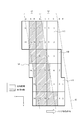
- FIG. 4 is a diagram illustrating a state when the user's eyes are located at the reference position with respect to the display panel 5.
- Each of the sub-pixels 11 with numbers r1 to r7, g1 to g7, and b1 to g7 in FIG. 4 displays a left-eye image because more than half of the region belongs to the first region 52.
- Each of the sub-pixels 11 with numbers r8 to r14, g8 to g14, and b8 to b14 in FIG. 4 displays a right-eye image because more than half of the region belongs to the second region 53.
- the sub-pixels 11 for displaying the left-eye image are shown without shading.
- the sub-pixels 11 for displaying the right-eye image are shaded in the figure.
- the group 54 extends over an array (rows) of the plurality of sub-pixels 11 arranged in the x direction and an array (columns) of the plurality of sub-pixels 11 arranged in the y direction on the active area 51.
- the group of sub-pixels in group 54 extends into a plurality of rows and a plurality of columns.
- the sub-pixel groups of the adjacent group 54 are shifted from each other in the x direction and the y direction.
- the controller 7 of FIG. 1 displays an image to be displayed on the sub-pixels 11 belonging to the group 54 according to the position of both eyes of the user detected by the detection device 2 in one of a left-eye image and a right-eye image. Is determined.
- the red sub-pixel 11R of numbers r1 to r7, the green sub-pixel 11G of numbers g1 to g7, and the blue sub-pixel 11B of numbers b1 to b7 are the sub-pixels 11 for displaying the left eye image.
- the red sub-pixel 11R of numbers r8 to r14, the green sub-pixel 11G of numbers g8 to g14, and the blue sub-pixel 11B of numbers b8 to b14 are the sub-pixels 11 for displaying the right-eye image.
- FIGS. 5 to 12 show the case where the position of the parallax barrier 6 viewed from the user's eye located at an appropriate viewing distance is sequentially displaced from the position of FIG. 4 to the negative side (the direction of the arrow) in the x direction.
- FIG. 9 is a diagram illustrating a change in an image displayed by each sub-pixel 11 of a group 54. 5 to 12, the position of the parallax barrier 6 is indicated by a contour 63 of the parallax barrier 6.
- Such displacement of the parallax barrier 6 may occur when the user's eyes move to the left relative to the image display device 3. With the displacement of the outline 63, the first region 52 and the second region 53 sandwiched between the outlines 63 are displaced.
- FIG. 5 shows an arrangement of sub-pixels 11 for displaying a left-eye image and a right-eye image when the left eye and the right eye of the user are located at the same reference position as in FIG.
- FIG. 6 shows a state where the position of the parallax barrier 6 viewed from the user's eyes is displaced from the state of FIG.
- the image displayed by the red sub-pixel 11R of the number r7 is changed from the left-eye image to the right-eye image.
- the image displayed by the red sub-pixel 11R of the number r14 changes from the right-eye image to the left-eye image.
- the display switching between the right-eye image and the left-eye image is performed between the red sub-pixels 11R of the numbers r7 and r14.
- the position of the parallax barrier 6 viewed from the user's eyes is further displaced to the negative side in the x direction (the direction of the arrow). Accordingly, as shown in FIG. 7, the image displayed by the green sub-pixel 11G of the number g7 is changed from the left-eye image to the right-eye image. At the same timing as the image displayed by the green sub-pixel 11G of the number g7 changes, the image displayed by the green sub-pixel 11G of the number g14 changes from the right-eye image to the left-eye image. Further, as shown in FIG. 8, the image displayed by the blue sub-pixel 11B of the number b7 is changed from the left-eye image to the right-eye image. At the same timing as the image displayed by the blue sub-pixel 11B of the number b7 changes, the image displayed by the blue sub-pixel 11B of the number b14 changes from the right-eye image to the left-eye image.
- the position of the parallax barrier 6 is further displaced sequentially to the negative side in the x direction. Accordingly, first, as shown in FIG. 9, display switching between the left-eye image and the right-eye image is performed between the two red sub-pixels 11R of numbers r6 and r13. Next, as shown in FIG. 10, the display of the left-eye image and the display of the right-eye image are switched between the two green sub-pixels 11G with the numbers g6 and g13. Further, as shown in FIG. 11, the display switching between the left-eye image and the right-eye image is performed between the two blue sub-pixels 11B of the numbers b6 and b13.
- FIG. 12 shows a state in which the parallax barrier 6 is further displaced.
- the display of the left-eye image and the right-eye image is sequentially switched between the red sub-pixel 11R of numbers r5 and r12, the green sub-pixel 11G of numbers g5 and g12, and the blue sub-pixel 11B of numbers b5 and b12. Be done. Further, when the parallax barrier 6 is displaced, the display image is similarly switched between the sub-pixels. Thereby, even if the position of the user's eyes changes, the display panel 5 can continue to display the stereoscopic image to the user.
- the controller 7 is configured to control the plurality of sub-pixels 11 including the red sub-pixel 11R, the green sub-pixel 11G, and the blue sub-pixel 11B included in the group 54 as the group 54.
- the controller 7 displays the image displayed by another red sub-pixel 11R belonging to the same group 54. Is changed from the right-eye image to the left-eye image. The same applies when changing the images displayed by the green sub-pixel 11G and the blue sub-pixel 11B.
- the controller 7 is configured to switch the sub-pixels 11 indicated by the same number between the left-eye image and the right-eye image at the same timing in all the groups 54.
- the first timing at which the controller 7 changes the image displayed by the red sub-pixel 11R between the left-eye image and the right-eye image is determined by changing the image displayed by the green sub-pixel 11G to the right-eye image and the right-eye image. This may be different from the second timing for changing between the eye image and the eye image. Further, the third timing for changing the image displayed by the blue sub-pixel 11B between the left-eye image and the right-eye image may be different from the first timing and the second timing.
- the widths in the x direction of the red subpixel 11R, the green subpixel 11G, and the blue subpixel 11B are not equal.
- the positions where the display images of the red sub-pixel 11R, the green sub-pixel 11G, and the blue sub-pixel 11B are switched with respect to the apparent displacement of the parallax barrier 6 are not the same.
- the apparent displacement of the parallax barrier 6 corresponds to the displacement of the user's head.
- the red sub-pixels 11R are arranged at equal intervals in the x-direction at a pitch of one pixel. Therefore, the red sub-pixel 11R can be controlled based on the displacement of the user's head from the switching origin, based on the switching origin independent of the green sub-pixel 11G and the blue sub-pixel 11B. The same applies to the green sub-pixel 11G and the blue sub-pixel 11B.
- the switching origin can be adjusted for each color of the sub-pixel 11.
- a method of adjusting the switching origin of the red sub-pixel 11R will be described with reference to FIG.
- the controller 7 displays all the green sub-pixels 11G and the blue sub-pixels 11B in black.
- the black display is a display of a gradation with the lowest luminance of the sub-pixel 11.
- the outline of the sub-pixel 11 in the black display is indicated by a broken line.
- an image for the left eye is displayed on the red sub-pixels 11R of numbers r2 to r7
- an image for the right eye is displayed on the red sub-pixels 11R of numbers r9 to r14.
- the user switches the images displayed on the red sub-pixel 11R of the number r1 and the red sub-pixel 11R of the number r8 between the left-eye image and the right-eye image,
- the position of the head is adjusted in the x direction.
- a position where no change is observed in the displayed image can be set as the reference position.
- the user can adjust the reference positions of the green sub-pixel 11G and the blue sub-pixel 11B while the other color sub-pixels 11 are displayed in black.
- the information on the reference position can be stored in the storage unit of the controller 7.
- the controller 7 performs independent switching control between the left-eye image and the right-eye image based on each switching origin for each of the red subpixel 11R, the green subpixel 11G, and the blue subpixel 11B. It is configured to be able to. Accordingly, regardless of the difference in the length of the red sub-pixel 11R, the green sub-pixel 11G, and the blue sub-pixel 11B along the x direction, the image displayed on the sub-pixel 11 is set between the left-eye image and the right-eye image. It is possible to switch with.
- the controller 7 sets the 14 red sub-pixels 11R, the green sub-pixel 11G, and the blue sub-pixel 11B as one group 54, and displays the image displayed on each sub-pixel 11 with the left-eye image and the right-eye image. Switching processing was performed between eye images.
- the image display device 3 of the present disclosure can employ the configuration of the group 54 having the arrangement pattern of the other sub-pixels 11 and the configuration of the parallax barrier 6 corresponding to the group 54.
- a method of designing the parallax barrier 6 and a method of arranging the sub-pixels 11 of the group 54 will be described with reference to FIG.
- the pitch in the x direction (horizontal pitch) of the pixels 12 on the active area 51 is Hp
- the pitch in the y direction (vertical pitch) is Vp
- the barrier inclination angle of the parallax barrier 6 projected on the active area 51 is ⁇
- the active area is The image pitch on 51 is k.
- the barrier inclination angle ⁇ is the inclination angle of the parallax barrier 6 projected onto the active area 51 from the position of the user's eye located at an appropriate viewing distance. More specifically, the barrier inclination angle ⁇ is the angle of the direction in which the projection of the light transmitting area 62 and the light reducing area 61 on the active area 51 extends with respect to the y direction.
- the image pitch k is an x-direction pitch of the dimming area 61 and the light transmitting area 62 of the parallax barrier 6 projected onto the active area 51 from a point of an appropriate viewing distance where the user's eyes are arranged.
- the image pitch k is equal to the width in the x direction of the combined area of the adjacent first area 52 and second area 53.
- the barrier inclination angle ⁇ is such that the contour 63 indicating the boundary between the light-reducing area 61 and the light-transmitting area 62 of the parallax barrier 6 projected on the active area 51 crosses a natural number a of horizontal pitches Hp. It is set so as to cross the natural number b vertical pitches Vp in between. That is, the barrier inclination angle ⁇ (the third direction) is a direction in which the pixel advances by a pixel in the x direction and a pixel advances by b pixels in the y direction.
- a and b a combination of integers other than 0 that are relatively prime can be adopted.
- the image pitch k is determined by setting the horizontal distance between the straight lines to half of the image pitch k.
- two straight lines having the barrier inclination angle ⁇ pass through the two vertices A and B.
- k 8Hp / 3.
- the two vertices A and B can be arbitrarily selected. For example, in FIG. 14, instead of a straight line passing through the vertex B, a straight line passing through the vertex C or the vertex D may be selected.
- the number of pixels included in one group 54 is calculated based on the image pitch k.
- the number 2n of pixels included in the group 54 and the image pitch k have a relationship represented by the following equation (2).
- 2n is equal to the number of sub-pixels 11 of each color included in the group 54.
- 2n is 8.
- 2n is 14.
- the sub-pixels 11 included in the group 54 are arranged on two straight lines having an inclination of the barrier inclination angle ⁇ and between the two straight lines, and are arranged in a range of a height of b pixels in the vertical direction. be able to.
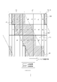
- FIG. 15 shows a group 54 of the sub-pixels 11 according to the second example.
- the red sub-pixel 11R of numbers r1 to r3, the green sub-pixel 11G of numbers g1 to g3, and the blue sub-pixel 11B of numbers b1 to b3 display the left eye image.
- the red sub-pixel 11R of numbers r4 to r6, the green sub-pixel 11G of numbers g4 to g6, and the blue sub-pixel 11B of numbers b4 to b6 display the image for the right eye.
- the controller 7 sets the left eye between the green sub-pixel 11G of number g6 and the green sub-pixel 11G of number g3. Switching between the image and the right eye image is performed. Next, the controller 7 controls the left-eye image and the right-eye image between the red subpixel 11R of number r6 and the red subpixel 11R of number r3, and the blue subpixel 11B of number b6 and the blue subpixel 11B of number b3. Switch the display with the image. Similarly, the image displayed by each of the two sub-pixels 11 of the same color is sequentially switched between the left-eye image and the right-eye image.
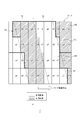
- FIG. 16 shows a group 54 of the sub-pixels 11 according to the third example.
- a red sub-pixel 11R of numbers r1 to r5 a green sub-pixel 11G of numbers g1 to g5, and a blue sub-pixel 11B of numbers b1 to b5 display an image for the left eye.
- the red sub-pixel 11R of numbers r6 to r10, the green sub-pixel 11G of numbers g6 to g10, and the blue sub-pixel 11B of numbers b6 to b10 display the right-eye image.
- the controller 7 sets the left eye between the green sub-pixel 11G of the number g10 and the green sub-pixel 11G of the number g5. Switching between the image and the right eye image is performed. Next, the controller 7 controls the left-eye image and the right-eye image between the red sub-pixel 11R of number r10 and the red sub-pixel 11R of number r5, and the blue sub-pixel 11B of number b10 and the blue sub-pixel 11B of number b5. Replace with image. Similarly, the images displayed by the two sub-pixels 11 of the same color are sequentially switched between the left-eye image and the right-eye image.
- the controller 7 is displayed on the sub-pixel 11 while using the display panel 5 in which the length of the sub-pixel 11 in the parallax direction is different.
- the image for the right eye and the image for the left eye can be appropriately switched.
- the occurrence of crosstalk can be reduced while maintaining a high aperture ratio, so that a three-dimensional image can be appropriately displayed without lowering the brightness of the image.
- the user of the image display system 1 and the image display device 3 can appropriately view the three-dimensional image.
- the parallax barrier 6 As an optical element configured to regulate the light beam direction of the image displayed on the display panel 5, a three-dimensional image can be displayed with a simple configuration. Further, since the dimming region 61 of the parallax barrier 6 extends in an oblique direction intersecting the x direction and the y direction, it is possible to reduce the occurrence of moire.
- the controller 7 is configured to change the left-eye image and the right-eye image at different timings for each of the colors R, G, and B.
- the controller 7 is configured to adjust the switching origin for each of the R, G, and B colors, and to control the switching timing independently for each of the colors. Accordingly, it is possible to switch the image displayed by the sub-pixel 11 at an appropriate timing, corresponding to various lengths in the x direction that are different for each color of the sub-pixel 11.
- the design method of the present disclosure can appropriately determine the group 54 of the sub-pixels 11 controlled by the parallax barrier 6 and the controller 7 when using the display panel 5 in which the lengths of the sub-pixels 11 in the parallax direction are different.
- the design method of the present disclosure can design the image display system 1 and the image display device 3 that realize three-dimensional image display.
- the image display system 1 and the image display device 3 can set the image pitch k to various values. Thereby, the degree of freedom of design of the image display system 1 and the image display device 3 increases.
- FIG. 17 shows an image display system 1A according to one of the plurality of embodiments. 17, components that are the same as or similar to the image display system 1 of FIG. 1 are given the same reference numerals, and descriptions thereof will be omitted.
- the image display device 3 has the parallax barrier 6 as an optical element.
- the image display device 3A of the image display system 1A can have a lenticular lens 9 instead of the parallax barrier 6 as an optical element.
- the lenticular lens 9 can be configured by arranging fine elongated semi-cylindrical cylindrical lenses 10 that extend obliquely with respect to the x direction and the y direction.
- the image display system 1A shown in FIG. 17 is of a type in which the user looks directly at the display panel 5. For this reason, the display surface 71 in the space visually perceived by the user matches the active area 51.
- the areas on the active area 51 of the display panel 5 configured to be visible from the left and right eyes of the user located at the appropriate viewing distance can be the first area 52 and the second area 53, respectively.
- the lenticular lens 9 is configured to deflect the image light of the left eye image emitted from the first area 52 of the display panel 5 toward the left eye of the user.
- the lenticular lens 9 is configured to deflect the image light of the right eye image emitted from the second area 53 of the display panel 5 toward the right eye of the user located at an appropriate viewing distance.
- the lenticular lens 9 is an optical element configured to regulate the light beam direction of an image displayed on the display panel 5.
- the display positions of the sub-pixels 11 of the left-eye image and the right-eye image on the active area 51 take into account the effects of refraction and deflection of image light by the respective cylindrical lenses 10 of the lenticular lens 9.
- the display panel 5 has a different length along the x direction for each color.
- the controller 7 controls the display switching of the left-eye image and the right-eye image of each sub-pixel 11 similarly to the case where the parallax barrier 6 is used. can do. That is, the image display system 1A and the image display device 3A appropriately display a three-dimensional image without reducing the brightness of the image while using the display panel 5 in which the length of the sub-pixel 11 in the x direction is different for each color. It becomes possible to do.
- the image display system 1B can be mounted on the head-up display 100.
- the image display system 1B has the same or similar configuration as the image display system 1 of FIG. 1 except that the user does not look directly at the display panel 5.
- the image display system 1B includes an image display device 3 and a detection device 2. Components of the image display system 1B that are the same as or similar to the image display system 1 are denoted by the same reference numerals as those of the image display system 1, and description thereof is omitted.
- the head-up display 100 is also called a HUD (Head Up Display).
- the HUD 100 includes an image display system 1B, one or more optical members 110, and a projection member 120 having a projection surface 130.
- the optical member 110 and the projection target member 120 are included in an optical system that projects an image displayed in the active area 51 so as to form a virtual image on a user's visual field.
- the optical member 110 and the projection target member 120 may be collectively referred to simply as an optical system.
- the optical member 110 and the projection target member 120 may be reflective optical members that reflect image light of a display image.
- the optical member 110 and the projection target member 120 may have a concave or convex reflecting surface.
- the HUD 100 is configured to cause the image light emitted from the image display system 1B to reach the projection surface 130 of the projection member 120 via the optical member 110.
- the HUD 100 is configured to cause the image light reflected on the projection surface 130 to reach the left and right eyes of the user. That is, the HUD 100 is configured to cause the image light to travel from the image display system 1 to the left and right eyes of the user along the optical path 140 indicated by the broken line. The user can visually recognize the image light that has arrived along the optical path 140 as a virtual image 150.
- the image display system 1 ⁇ / b> B is configured so that the detection device 2 detects the positions of the left eye and the right eye of the user.
- the controller 7 of the image display device 3 controls the image displayed on the display panel 5 according to the detected positions of the left eye and the right eye, thereby providing an image visually recognized as a stereoscopic image by the user. It is configured as follows.
- the display surface 71 is located at the position where the virtual image 150 is displayed.
- the position where the virtual image 150 is displayed is a position where the user visually recognizes the image displayed in the active area 51 as a virtual image.
- the HUD 100 may be mounted on a moving body 200 such as a vehicle.
- the HUD 100 may share a part of the configuration with other devices and components included in the moving body 200.
- the HUD 100 may use the windshield of the moving body 200 as the projected member 120 of the HUD 100.
- the HUD 100 of the present disclosure appropriately displays a three-dimensional image without reducing the brightness of the image while using the display panel 5 in which the length of the sub-pixel 11 in the parallax direction is different. can do. As a result, the HUD 100 can display a bright image even when the HUD 100 is mounted on the moving body 200 and the windshield is the projection target member 120.
- ⁇ “ Moving object ”in the present disclosure includes vehicles, ships, and aircraft.
- the “vehicle” in the present disclosure includes, but is not limited to, automobiles and industrial vehicles, and may include railway vehicles, domestic vehicles, and fixed-wing aircraft traveling on a runway.
- Automobiles include, but are not limited to, passenger cars, trucks, buses, motorcycles, trolleybuses, and the like, and may include other vehicles traveling on roads.
- Industrial vehicles include industrial vehicles for agriculture and construction.
- Industrial vehicles include, but are not limited to, forklifts and golf carts.
- Industrial vehicles for agriculture include, but are not limited to, tractors, tillers, transplanters, binders, combines, and lawnmowers.
- Industrial vehicles for construction include, but are not limited to, bulldozers, scrapers, excavators, crane trucks, dump trucks, and road rollers. Vehicles include those that run manually.
- the classification of the vehicle is not limited to the above.
- an automobile may include an industrial vehicle that can travel on a road, and a plurality of classifications may include the same vehicle.
- Ships in the present disclosure include marine jets, boats, and tankers.
- the aircraft according to the present disclosure includes a fixed wing aircraft and a rotary wing aircraft.
- descriptions such as “first” and “second” are identifiers for distinguishing the configuration.
- the numbers in the configurations can be exchanged.
- the identifiers “first” and “second” can be exchanged with the second direction.
- red is the first color
- green is the second color.
- the first and second colors may be arbitrarily replaced between red, blue and green. The same applies to the first sub-pixel and the second sub-pixel.
- the first eye and the second eye are the left eye and the right eye, respectively, but the first eye may be the right eye and the second eye may be the left eye.
- the exchange of identifiers takes place simultaneously. Even after the exchange of the identifier, the configuration is distinguished.
- the identifier may be deleted.
- the configuration from which the identifier is deleted is distinguished by a code. Interpretation of the order of the configuration, grounds for the existence of a small-numbered identifier, grounds for the existence of a large-numbered identifier based only on the description of identifiers such as “first” and “second” in the present disclosure Must not be used for
- the width in the x direction of the light-reducing region 61 and the light-transmitting region 62 of the parallax barrier 6 is the same. That is, the barrier aperture ratio of the parallax barrier 6 is 50%. In this case, the left eye of the user can visually recognize the entire first region 52. Further, the right eye of the user can visually recognize the entire second region 53.
- the barrier aperture ratio of the image display device 3 is not limited to 50%.
- the width of the light transmitting region 62 in the x direction can be made smaller than the width of the light reducing region 61 in the x direction.
- Crosstalk is a phenomenon in which a part of the left-eye image enters the right eye of the user and / or a part of the right-eye image enters the left eye of the user.
- the width of the light transmitting region 62 in the x direction is smaller than the width of the light reducing region 61 in the x direction, crosstalk can be reduced. In that case, the barrier aperture ratio is smaller than 50%.
Landscapes
- Engineering & Computer Science (AREA)
- Physics & Mathematics (AREA)
- Multimedia (AREA)
- Signal Processing (AREA)
- Chemical & Material Sciences (AREA)
- Combustion & Propulsion (AREA)
- Transportation (AREA)
- Mechanical Engineering (AREA)
- Optics & Photonics (AREA)
- General Physics & Mathematics (AREA)
- Testing, Inspecting, Measuring Of Stereoscopic Televisions And Televisions (AREA)
- Controls And Circuits For Display Device (AREA)
Abstract
画像表示装置は、表示パネルと、光学素子と、取得部と、コントローラとを含む。コントローラは、サブピクセルに表示される画像を、左眼画像と右眼画像との間で切り替えることができるように構成される。表示パネルは、x方向の幅の異なる赤色および緑色のサブピクセルを含む。コントローラは、複数のサブピクセルをグループとして制御するように構成され、且つ、1つのグループに属する一つの赤色のサブピクセルが表示する画像を左眼画像から右眼画像に変更する際に、同一のグループに属する他の一つの赤色のサブピクセルが表示する画像を左眼画像から右眼画像に変更するように構成される。
Description
本出願は、2018年6月26日に出願された日本国特許出願2018-121077号の優先権を主張するものであり、この先の出願の開示全体をここに参照のために取り込む。
本開示は、画像表示装置、画像表示システム、ヘッドアップディスプレイ、移動体および画像表示方法に関する。
水平および垂直方向に配列されたサブピクセルを有する表示パネルと、サブピクセルの対角線方向に延びる複数の帯状の視差バリアを用いて、左右の眼に視差画像を到達させ、3次元画像を表示する画像表示装置が提案されている(例えば、特許文献1参照)。視差バリアが対角線方向に延びることは、モアレ等の発生を低減することに寄与する。従来の3次元表示を行う画像表示装置では、左右の眼の視差方向のサブピクセルの長さは、等幅であることを前提としている。
本開示の一実施形態に係る画像表示装置は、表示パネルと、光学素子と、取得部と、コントローラとを含む。表示パネルは、利用者の視差方向に対応する第1方向および該第1方向に交わる第2方向に沿って格子配列される複数のサブピクセルを含む。光学素子は、前記表示パネルに表示される画像の光線方向を規定するように構成される。取得部は、前記利用者の第1眼の第1位置と該第1眼とは異なる第2眼の第2位置とを取得するように構成される。コントローラは、前記第1位置および前記第2位置に基づいて、第1画像と第2画像とを表示する表示位置を前記複数のサブピクセルに含まれるサブピクセルごとに切り替え可能に構成される。前記第1画像は、前記利用者の前記第1眼に視認させる画像である。前記第2画像は、前記利用者の前記第2眼に視認させる画像である。前記複数のサブピクセルは、第1色の光を発するように構成される複数の第1サブピクセルと、前記第1色と異なる第2色の光を発するように構成される複数の第2サブピクセルとを含み、前記第1サブピクセルと前記第2サブピクセルとは、前記第1方向に沿う長さが異なる。前記コントローラは、複数の前記第1サブピクセルおよび複数の前記第2サブピクセルを含む複数の前記サブピクセルをグループとして制御するように構成される。前記コントローラは、前記グループに属する一つの前記第1サブピクセルが表示する画像を前記第1画像から前記第2画像に変更する際に、前記グループに属する他の一つの前記第1サブピクセルが表示する画像を前記第2画像から前記第1画像に変更するように構成される。
本開示の一実施形態に係る画像表示システムは、表示パネルと、光学素子と、検出装置と、コントローラとを含む。表示パネルは、利用者の視差方向に対応する第1方向および該第1方向に交わる第2方向に沿って格子配列される複数のサブピクセルを含む。光学素子は、前記表示パネルに表示される画像の光線方向を規定するように構成される。検出装置は、前記利用者の第1眼の第1位置と該第1眼とは異なる第2眼の第2位置とを検出可能に構成される。コントローラは、前記検出装置により検出された前記第1位置および前記第2位置に基づいて、第1画像と第2画像とを表示する表示位置を前記複数のサブピクセルに含まれるサブピクセルごとに切り替え可能に構成される。前記第1画像は、前記利用者の前記第1眼に視認させる画像である。前記第2画像は、前記利用者の前記第2眼に視認させる画像である。前記複数のサブピクセルは、第1色の光を発するように構成される複数の第1サブピクセルと、前記第1色と異なる第2色の光を発するように構成される複数の第2サブピクセルとを含み、前記第1サブピクセルと前記第2サブピクセルとは、前記第1方向に沿う長さが異なる。前記コントローラは、複数の前記第1サブピクセルおよび複数の前記第2サブピクセルを含む複数の前記サブピクセルをグループとして制御するように構成される。前記コントローラは、前記グループに属する一つの前記第1サブピクセルが表示する画像を前記第1画像から前記第2画像に変更する際に、前記グループに属する他の一つの前記第1サブピクセルが表示する画像を前記第2画像から前記第1画像に変更するように構成される。
本開示の一実施形態に係るヘッドアップディスプレイは、表示パネルと、光学素子と、検出装置と、コントローラと、光学系とを含む。表示パネルは、利用者の視差方向に対応する第1方向および該第1方向に交わる第2方向に沿って格子配列される複数のサブピクセルを含む。光学素子は、前記表示パネルに表示される画像の光線方向を規定するように構成される。検出装置は、前記利用者の第1眼の第1位置と該第1眼とは異なる第2眼の第2位置とを検出可能に構成される。コントローラは、前記検出装置により検出された前記第1位置および前記第2位置に基づいて、第1画像と第2画像とを表示する表示位置を前記複数のサブピクセルに含まれるサブピクセルごとに切り替え可能に構成される。前記第1画像は、前記利用者の前記第1眼に視認させる画像である。前記第2画像は、前記利用者の前記第2眼に視認させる画像である。光学系は、前記表示パネルおよび前記光学素子の前記利用者の眼の配置される側に配置された、前記表示パネルの虚像を投影するように構成される。前記複数のサブピクセルは、第1色の光を発するように構成される複数の第1サブピクセルと、前記第1色と異なる第2色の光を発するように構成される複数の第2サブピクセルとを含み、前記第1サブピクセルと前記第2サブピクセルとは、前記第1方向に沿う長さが異なる。前記コントローラは、複数の前記第1サブピクセルおよび複数の前記第2サブピクセルを含む複数の前記サブピクセルをグループとして制御するように構成される。前記コントローラは、前記グループに属する一つの前記第1サブピクセルが表示する画像を前記第1画像から前記第2画像に変更する際に、前記グループに属する他の一つの前記第1サブピクセルが表示する画像を前記第2画像から前記第1画像に変更するように構成される。
本開示の一実施形態に係る移動体は、ヘッドアップディスプレイを備える。ヘッドアップディスプレイは、表示パネルと、光学素子と、検出装置と、コントローラと、光学系とを含む。表示パネルは、利用者の視差方向に対応する第1方向および該第1方向に交わる第2方向に沿って格子配列される複数のサブピクセルを含む。光学素子は、前記表示パネルに表示される画像の光線方向を規定するように構成される。検出装置は、前記利用者の第1眼の第1位置と該第1眼とは異なる第2眼の第2位置とを検出するように構成される。コントローラは、前記検出装置により検出された前記第1位置および前記第2位置に基づいて、第1画像と第2画像とを表示する表示位置を前記複数のサブピクセルに含まれるサブピクセルごとに切り替え可能に構成される。前記第1画像は、前記利用者の前記第1眼に視認させる画像である。前記第2画像は、前記利用者の前記第2眼に視認させる画像である。光学系は、前記表示パネルおよび前記光学素子の前記利用者の眼の配置される側に配置された、前記表示パネルの虚像を投影するように構成される。前記複数のサブピクセルは、第1色の光を発するように構成される複数の第1サブピクセルと、前記第1色と異なる第2色の光を発するように構成される複数の第2サブピクセルとを含み、前記第1サブピクセルと前記第2サブピクセルとは、前記第1方向に沿う長さが異なる。前記コントローラは、複数の前記第1サブピクセルおよび複数の前記第2サブピクセルを含む複数の前記サブピクセルをグループとして制御するように構成される。前記コントローラは、前記グループに属する一つの前記第1サブピクセルが表示する画像を前記第1画像から前記第2画像に変更する際に、前記グループに属する他の一つの前記第1サブピクセルが表示する画像を前記第2画像から前記第1画像に変更するように構成される。
本開示の一実施形態に係る画像表示方法は、取得部により利用者の第1眼の第1位置と該第1眼とは異なる第2眼の第2位置を取得することを含む。画像表示方法は、コントローラにより、前記第1位置および前記第2位置に基づいて、複数のサブピクセルのそれぞれに、第1画像または第2画像を表示することを含む。前記複数のサブピクセルは、表示パネルに含まれる利用者の視差方向に対応する第1方向および該第1方向に交わる第2方向に沿って格子配列される。画像表示方法は、光学素子により、前記第1画像を前記利用者の第1眼に到達させ、前記第2画像を前記利用者の第2眼に到達させることを含む。前記複数のサブピクセルは、第1色の光を発するように構成される複数の第1サブピクセルと、前記第1色と異なる第2色の光を発するように構成される複数の第2サブピクセルとを含み、前記第1サブピクセルと前記第2サブピクセルとは、前記第1方向に沿う長さが異なる。前記コントローラは、複数の前記第1サブピクセルおよび複数の前記第2サブピクセルを含む複数の前記サブピクセルをグループとして制御するように構成される。コントローラは、前記グループに属する一つの前記第1サブピクセルが表示する画像を前記第1画像から前記第2画像に変更する際に、前記グループに属する他の一つの前記第1サブピクセルが表示する画像を前記第2画像から前記第1画像に変更するように構成される。
従来の3次元表示を行う画像表示装置では、一つのピクセルを構成する複数のサブピクセルは、それぞれ水平方向に同じ長さを有している。画像表示装置は、サブピクセルの面積を色ごとに変えたい場合がある。例えば、視感度の高いG(緑)のサブピクセルの面積を、R(赤)およびB(青)のサブピクセルの面積よりも広くして、画像表示装置の表示パネルの視感透過率を向上させたい場合がある。視感度とは、視覚に感じる明るさを表す量である。しかしながら、従来、サブピクセルの水平方向の長さが異なる場合に、左右の眼に到達する画像を制御する方法が無かった。仮に、サブピクセルの水平方向の幅が異なる場合、水平方向の長さが等しいサブピクセルを有する表示パネルを用いた場合と同じ方法で制御を行うと、サブピクセルの水平方向の位置のずれによりクロストークが発生する。このクロストークを低減するため、視差バリアの開口の幅を狭めると、開口率が低下し視感度が低下して画像が暗くなることとなる。
以下に述べる本開示の画像表示装置、画像表示システムおよびヘッドアップディスプレイは、サブピクセルの視差方向の長さが異なる場合に、画像の明るさを低下させること無く3次元画像を適切に表示することができる。
以下、本開示の実施形態について、図面を参照して説明する。以下の説明で用いられる図は模式的なものである。図面上の寸法比率等は現実のものとは必ずしも一致していない。
[画像表示システムの構成]
本開示の複数の実施形態の1つに係る画像表示システム1は、図1に示されるように、検出装置2および画像表示装置3を含んで構成される。図1は、画像表示システム1を、この画像表示装置3により画像を観察する利用者の上方から見た様子を示している。
本開示の複数の実施形態の1つに係る画像表示システム1は、図1に示されるように、検出装置2および画像表示装置3を含んで構成される。図1は、画像表示システム1を、この画像表示装置3により画像を観察する利用者の上方から見た様子を示している。
(検出装置)
検出装置2は、利用者の左眼の位置(第1位置)および右眼の位置(第2位置)を検出し、画像表示装置3に出力するように構成される。検出装置2は、例えば、カメラを備えてよい。検出装置2は、カメラによって利用者の顔を撮影できるように構成されてよい。検出装置2は、カメラの撮影画像から左眼および右眼の少なくとも一方の位置を検出するように構成されてよい。検出装置2は、1個のカメラの撮影画像から、左眼および右眼の少なくとも一方の位置を3次元空間の座標として検出するように構成されてよい。検出装置2は、2個以上のカメラの撮影画像から、左眼および右眼の少なくとも一方の位置を3次元空間の座標として検出するように構成されてよい。
検出装置2は、利用者の左眼の位置(第1位置)および右眼の位置(第2位置)を検出し、画像表示装置3に出力するように構成される。検出装置2は、例えば、カメラを備えてよい。検出装置2は、カメラによって利用者の顔を撮影できるように構成されてよい。検出装置2は、カメラの撮影画像から左眼および右眼の少なくとも一方の位置を検出するように構成されてよい。検出装置2は、1個のカメラの撮影画像から、左眼および右眼の少なくとも一方の位置を3次元空間の座標として検出するように構成されてよい。検出装置2は、2個以上のカメラの撮影画像から、左眼および右眼の少なくとも一方の位置を3次元空間の座標として検出するように構成されてよい。
検出装置2は、カメラを備えず、装置外のカメラに接続されていてよい。検出装置2は、装置外のカメラからの信号を入力する入力端子を備えてよい。装置外のカメラは、入力端子に直接的に接続されてよい。装置外のカメラは、ネットワークを介して入力端子に間接的に接続されてよい。カメラを備えない検出装置2は、カメラが映像信号を入力する入力端子を備えてよい。カメラを備えない検出装置2は、入力端子に入力された映像信号から左眼および右眼の少なくとも一方の位置を検出するように構成されてよい。
検出装置2は、例えば、センサを備えてよい。センサは、超音波センサまたは光センサ等であってよい。検出装置2は、センサによって利用者の頭部の位置を検出し、頭部の位置に基づいて左眼および右眼の少なくとも一方の位置を検出するように構成されてよい。検出装置2は、1個または2個以上のセンサによって、左眼および右眼の少なくとも一方の位置を3次元空間の座標として検出するように構成されてよい。
検出装置2は、左眼および右眼の一方の位置を検出した場合、使用者の眼間距離の情報または一般的な眼間距離の情報から、他方の眼の位置を推定するように構成されてよい。検出装置2が、一方の眼の位置を検出して他方の眼の位置を推定した場合は、左眼および右眼の位置を検出したものとする。
(画像表示装置)
本開示の一実施形態において、画像表示装置3は、照射器4、表示装置としての表示パネル5、光学素子としての視差バリア6、コントローラ7、および、取得部8を含んで構成される。
本開示の一実施形態において、画像表示装置3は、照射器4、表示装置としての表示パネル5、光学素子としての視差バリア6、コントローラ7、および、取得部8を含んで構成される。
照射器4は、表示パネル5の一方の面側に配置され、表示パネル5を面的に照射するように構成される。照射器4は、表示パネル5から見て利用者と反対側に配置される。照射器4は、光源、導光板、拡散板、拡散シート等を含んで構成されてよい。照射器4は、光源により照射光を射出し、導光板、拡散板、拡散シート等により照射光を表示パネル5の面方向に均一化するように構成される。照射器4は均一化された光を表示パネル5の方に出射するように構成される。
表示パネル5は、例えば透過型の液晶表示パネルなどの表示パネルを採用しうる。本願において、表示パネル5の実際の画像が表示される領域をアクティブエリア51とよぶ。表示パネル5は、種々な画像をアクティブエリア51に表示するように構成される。本開示において、利用者が視覚的に捉える空間での表示パネル5のアクティブエリア51を表示面71とする。利用者と表示パネル5のアクティブエリア51との間にレンズ、凹面鏡および/または凸面鏡等が介在せず、利用者が表示パネル5のアクティブエリア51を直接視覚的に捉えるとき、表示面71は、表示パネル5のアクティブエリア51の位置と一致する。利用者が表示パネル5のアクティブエリア51を虚像として捉えるとき、表示面71は、表示パネル5のアクティブエリア51の虚像の位置と一致する。利用者が表示パネル5のアクティブエリア51を虚像として捉えるとき、利用者は、表示パネル5の実体が無い空間において、表示面71上のアクティブエリア51を視覚的に捉える。
表示パネル5のアクティブエリア51は、図2に示されるように、第1方向(x方向)および第1方向に交わる第2方向(y方向)に沿って格子配列される複数のサブピクセル11を含む。第2方向は第1方向に略直交する方向としうる。図2において、表示面71はアクティブエリア51に一致する。第1方向は、利用者の両眼に視差を与える視差方向に対応する。利用者が通常の着席または直立した姿勢で表示パネル5を直接見るタイプの画像表示装置3において、第1方向は利用者から観た水平方向とすることができる。また、第2方向は利用者から観た垂直方向とすることができる。以下では、第1方向をx方向、第2方向をy方向として説明する。表示パネル5を示す各図において、x方向は右から左へ向かう方向として示す。y方向は、上から下へ向かう方向として示す。また、x方向およびy方向に直交し、利用者の眼の側に向く方向をz方向とする。
一実施形態において、サブピクセル11は、x方向よりもy方向に長い。各サブピクセル11はR(赤色(第1色)),G(緑色(第2色)),B(青色)のいずれかの色に対応する。以下において、R、G、Bそれぞれの色の光を発するように構成されるサブピクセル11を赤色サブピクセル11R(第1サブピクセル)、緑色サブピクセル11G(第2サブピクセル)、青色サブピクセル11Bと表記することがある。赤色サブピクセル11R、緑色サブピクセル11Gおよび青色サブピクセル11Bのx方向に沿う長さを、それぞれ第1長さ、第2長さおよび第3長さとするとき、第1長さ、第2長さおよび第3長さの比は、任意に設定することができる。以下の本実施形態の説明では、第1長さ、第2長さおよび第3長さの比を、1:2:1とする。所定数のサブピクセル11はピクセル12を構成することができる。赤色サブピクセル11R、緑色サブピクセル11G、および、青色サブピクセル11Bの3つのサブピクセル11は、一組として1つのピクセル12を構成することができる。図2において、説明のため幾つかのピクセルを太線により強調して表示している。1つのピクセル12は、1画素と呼びうる。1ピクセルのx方向の長さとy方向の長さとは、1:1に設定することができるが、これに限定されない。x方向は、例えば、1つのピクセル12を構成する複数のサブピクセル11が並ぶ方向である。x方向のサブピクセル11の配列を適宜「行」と呼ぶ。y方向は、例えば、同じ色のサブピクセル11が並ぶ方向である。y方向のサブピクセル11の配列を適宜「列」と呼ぶ。図2において、説明のため上部に表示したR,G,Bは、各列のサブピクセル11の色を示す。
表示パネル5としては、透過型の表示パネルに限られず、自発光型の表示パネル等他の表示パネルを使用することもできる。透過型の表示パネルは、液晶パネルの他に、MEMS(Micro Electro Mechanical Systems)シャッター式の表示パネルを含む。自発光型の表示パネルは、有機EL(electro-luminescence)、および無機ELの表示パネルを含む。表示パネル5として、自発光型の表示パネルを使用した場合、照射器4は不要となる。
視差バリア6は、表示パネル5の各サブピクセル11から射出される画像光の光線方向を規定するように構成される光学素子である。視差バリア6は、例えば、図3に示されるように、複数の減光領域61(光学要素)と複数の透光領域62とを有する。複数の減光領域61および複数の透光領域62は、所定方向に伸びる帯状(スリット状)としうる。視差バリア6の減光領域61および透光領域62は、表示パネル5に対向して配置される。複数の減光領域61および複数の透光領域62は、x方向に沿って交互に並びうる。複数の減光領域61は互いに略等しい幅を有して、x方向に周期的に並ぶ。複数の透光領域62は、互いに略等しい幅を有して、x方向に沿って周期的に並ぶ。透光領域62のx方向の幅は、減光領域61のx方向の幅以下とすることができる。以下の説明では、透光領域62のx方向の幅は、減光領域61のx方向の幅と等しいものとする。この場合、視差バリア6のバリア開口率は50%である。バリア開口率とは、視差バリア6のx方向のピッチ(すなわち、減光領域61のx方向の幅と透光領域62のx方向の幅の合計)に対する、透光領域62のx方向の幅の比率である。バリア開口率が狭いと、画像は暗くなる。サブピクセル11から射出される画像光は、視差バリア6によって、左眼および右眼のそれぞれに対して視認可能な範囲が定まる。視差バリア6は、図1に示されるように、表示パネル5に対して照射器4の反対側に位置することができる。他の実施形態においては、視差バリア6は、表示パネル5の照射器4側に位置することができる。
透光領域62は、視差バリア6に入射する光を透過させる部分である。透光領域62は、第1所定値以上の透過率で光を透過させてよい。第1所定値は、例えば略100%であってよいし、100%未満の値であってよい。アクティブエリア51から射出される画像光が良好に視認できる範囲であれば、第1所定値は、100%以下の値、例えば、80%または50%などとしうる。減光領域61は、視差バリア6に入射する光を減光させて殆ど透過させない部分である。言い換えれば、減光領域61は、表示パネル5のアクティブエリア51に表示される画像から射出される画像光が、利用者の眼に到達する割合を大幅に低減し、又は、事実上遮るように構成される。減光領域61は、第2所定値以下の透過率で光を遮ってよい。第2所定値は、例えば略0%であってよいし、0%より大きく、0.5%、1%または3%等、0%に近い値であってよい。第1所定値は、第2所定値よりも数倍以上、例えば、10倍以上、又は100倍以上大きい値としうる。
図3に示すように、透光領域62と減光領域61とは、xy平面に沿う方向に交互に配列される。減光領域61と透光領域62との境界を示す線は、y方向に対して所定角度θで傾斜する方向に延在する。減光領域61と透光領域62との境界を示す線は、減光領域61と透光領域62との境界線ともいう。所定角度θは、バリア傾斜角ともいう。バリア傾斜角θは、0度より大きく90度より小さい角度であってよい。仮に、減光領域61および透光領域62が図3におけるy方向に沿い、サブピクセル11の配列方向に一致する場合、サブピクセル11の配置または透光領域62の寸法に含まれる誤差によって、表示画像においてモアレが認識されやすくなる。減光領域61および透光領域62の延在する方向(第3方向)が図3におけるx方向およびy方向と交わる場合、サブピクセル11の配置または透光領域62の寸法に含まれる誤差にかかわらず、表示画像においてモアレが認識されにくくなる。
視差バリア6は、第2所定値未満の透過率を有するフィルムまたは板状部材で構成されてよい。この場合、減光領域61は、当該フィルムまたは板状部材で構成される。この場合、透光領域62は、フィルムまたは板状部材に設けられた開口で構成される。フィルムは、樹脂で構成されてよいし、他の材料で構成されてよい。板状部材は、樹脂または金属等で構成されてよいし、他の材料で構成されてよい。視差バリア6は、フィルムまたは板状部材に限られず、他の種類の部材で構成されてよい。視差バリア6は、減光性を有する基材で構成されてよい。視差バリア6は、減光性を有する添加物を含有する基材で構成されてよい。視差バリア6は、透光性を有する基材の上に、減光性を有する部材が部分的に重なった構成としうる。視差バリア6は、透光性を有する基材の一部に、減光性を有する部材が添加された構成としうる。
視差バリア6は、液晶シャッターで構成されてよい。液晶シャッターは、印加する電圧に応じて光の透過率を制御しうるように構成される。液晶シャッターは、複数の画素で構成され、各画素における光の透過率を制御してよい。液晶シャッターは、光の透過率が高い領域または光の透過率が低い領域を任意の形状に形成されてよい。視差バリア6が液晶シャッターで構成される場合、透光領域62は、第1所定値以上の透過率を有する領域としてよい。視差バリア6が液晶シャッターで構成される場合、減光領域61は、第2所定値以下の透過率を有する領域としてよい。視差バリア6は、微小領域ごとに透光状態と減光状態とで可変可能に構成されるシャッターパネルを含む。当該シャッターパネルは、液晶シャッターの他に、MEMS(Micro Electro Mechanical System)シャッターを採用したMEMSシャッターパネルを含む。
コントローラ7は、画像表示システム1の各構成要素に接続され、各構成要素を制御するように構成される。コントローラ7は、例えばプロセッサとして構成される。コントローラ7は、1以上のプロセッサを含んでよい。プロセッサは、特定のプログラムを読み込ませて特定の機能を実行する汎用のプロセッサ、および特定の処理に特化した専用のプロセッサを含んでよい。専用のプロセッサは、特定用途向けIC(ASIC:Application Specific Integrated Circuit)を含んでよい。プロセッサは、プログラマブルロジックデバイス(PLD:Programmable Logic Device)を含んでよい。PLDは、FPGA(Field-Programmable Gate Array)を含んでよい。コントローラ7は、1つまたは複数のプロセッサが協働するSoC(System-on-a-Chip)、およびSiP(System In a Package)のいずれかであってよい。コントローラ7は、記憶部を備え、記憶部に各種情報、または画像表示システム1の各構成部を動作させるためのプログラム等を格納してよい。記憶部は、例えば半導体メモリ等で構成されてよい。記憶部は、コントローラ7のワークメモリとして機能してよい。
取得部8は、検出装置2から左眼の位置および右眼の位置の情報を取得し、コントローラ7に引き渡すように構成される。取得部8は、検出装置2からの入力を受ける入力端子を備える。入力端子は、電気信号による伝送に対応した電気コネクタ、および、光信号による伝送に対応した光コネクタを含む。コントローラ7は、取得部8により取得した左眼の位置および右眼の位置に基づいて、表示パネル5の複数のサブピクセル11に含まれるサブピクセル11ごとに表示される画像を制御するように構成される。以下に、コントローラ7による画像表示方法について説明する。
[3次元画像の表示方法]
図4を用いて、表示パネル5のアクティブエリア51上の3次元画像の表示方法について説明する。図4では、説明のため利用者の左眼(第1眼)から見た視差バリア6の輪郭線63が、アクティブエリア51上に二点鎖線で示されている。すなわち、図4に示される視差バリア6の輪郭線63は、視差バリア6が利用者の左眼が配置される適視距離の点からアクティブエリア51上に射影されたものである。本願において「射影」とは、目的とする物体外のある基準点からその物体上の全ての点を光路に沿って直線で結び、それらの直線とその物体が射影される平面との交点により形成される図形を意味する。また、「射影する」とは、その物体の射影を平面上に形成することを意味する。基準点と物体が射影される平面との間にレンズ、ミラー等の光学素子がある場合、基準点と物体上の点とを結ぶ直線は、光学素子の有する光学効果により屈折、偏向等を受ける光路に沿うものとする。
図4を用いて、表示パネル5のアクティブエリア51上の3次元画像の表示方法について説明する。図4では、説明のため利用者の左眼(第1眼)から見た視差バリア6の輪郭線63が、アクティブエリア51上に二点鎖線で示されている。すなわち、図4に示される視差バリア6の輪郭線63は、視差バリア6が利用者の左眼が配置される適視距離の点からアクティブエリア51上に射影されたものである。本願において「射影」とは、目的とする物体外のある基準点からその物体上の全ての点を光路に沿って直線で結び、それらの直線とその物体が射影される平面との交点により形成される図形を意味する。また、「射影する」とは、その物体の射影を平面上に形成することを意味する。基準点と物体が射影される平面との間にレンズ、ミラー等の光学素子がある場合、基準点と物体上の点とを結ぶ直線は、光学素子の有する光学効果により屈折、偏向等を受ける光路に沿うものとする。
表示パネル5のアクティブエリア51から射出し、視差バリア6の透光領域62を透過した画像光は、利用者の眼に到達する。利用者の左眼は、透光領域62に対応する帯状領域として、アクティブエリア51上の第1領域52を視認しうる。視差バリア6の減光領域61に対応するアクティブエリア51上の第2領域53から射出される画像光は、利用者の左眼に到達する前に減光される。利用者の左眼は、減光領域61に対応するアクティブエリア51上の第2領域53を殆ど視認できない。
一方、図1から理解されるように、画像表示システム1において、利用者の右眼(第2眼)から見たとき、利用者は、透光領域62を介して、アクティブエリア51上の第2領域53を視認しうる。視差バリア6の減光領域61によって画像光が遮られることによって、利用者の右眼は、アクティブエリア51上の第1領域52を視認できない。
左眼から視認可能な第1領域52と、右眼から視認可能な第2領域53とに、互いに視差を有する画像を表示することによって、利用者の視界に対して3次元画像と認識される画像を表示することができる。以下に、左眼に投影するための画像を左眼画像(第1画像)、右眼に投影するための画像を右眼画像(第2画像)と呼ぶ。以上の説明のように、視差バリア6の複数の透光領域62は、第1領域52に表示される左眼画像を利用者の左眼に向かう光路の方向に透過させるように構成される。また、視差バリア6の複数の透光領域62は、第2領域53に表示される右眼画像を利用者の右眼に向かう光路の方向に透過させるように構成される。
コントローラ7は、利用者の左右の眼の位置と、表示パネル5および視差バリア6の構成に応じて、サブピクセル11ごとに表示される画像を左眼画像および右眼画像との間で切り替えるように構成される。コントローラ7は、利用者の左右の眼の位置と、表示パネル5および視差バリア6の構成に応じて、それぞれのサブピクセル11ごとに表示される画像を、左眼画像と右眼画像との何れか決定するように構成される。コントローラ7は、複数のサブピクセル11の中から、左眼画像を表示するサブピクセル11と、右眼画像を表示するサブピクセル11とを決定しうるように構成される。全体が第1領域52に属するサブピクセル11は、左眼画像を表示するように制御される。全体が第2領域53に属するサブピクセル11は、右眼画像を表示するように制御される。部分的に第1領域52に属し、且つ、部分的に第2領域53に属するサブピクセル11は、第2領域53よりも第1領域52に多く重複している場合、左眼画像を表示するように制御される。部分的に第1領域52に属し、且つ、部分的に第2領域53に属するサブピクセル11は、第1領域52よりも第2領域53に多く重複している場合、右眼画像を表示するように制御される。
コントローラ7は、同一のグループ54に属する複数のサブピクセル11を一つの制御単位として制御するように構成される。図4において、説明のためグループ54の外周を太線により強調して示している。グループ54は、左眼画像を表示するサブピクセル11および右眼画像を表示するサブピクセル11についての同一の配置パターンを有する複数のサブピクセル11の最小の纏まりである。コントローラ7は、同一の配置パターンで配置されるグループ54のサブピクセル11をアクティブエリア51上で2次元的に繰り返し配列することにより、全体の画像を規則的に再構成することができるように構成される。各サブピクセル11の左眼画像および右眼画像の表示は、グループ54に基づいて制御することができる。
一つのグループ54は、複数のサブピクセル11を含む。それぞれのグループ54には、異なるグループ間で、左眼画像を表示するサブピクセル11および右眼画像を表示するサブピクセル11が同じ位置関係で並ぶ。それぞれのグループ54には、赤色サブピクセル11R、緑色サブピクセル11Gおよび青色サブピクセル11Bが同じ位置関係で並ぶ。アクティブエリア51において、複数のグループ54は、x方向およびy方向において周期性を持って並んでいる。コントローラ7は、全てのグループ54のサブピクセル群に対して、同じ配置パターンで、左眼画像を表示するサブピクセル11と右眼画像を表示するサブピクセル11とを決定しうるように構成される。コントローラ7は、全てのグループ54で、対応する位置に位置するサブピクセル11の表示を、左眼画像と右眼画像との間で同時に切り替えるように構成される。一実施形態に係る左眼画像を表示するサブピクセル11と右眼画像を表示するサブピクセル11との配置方法の第1例を、図4を用いて説明する。
(サブピクセルのグループの第1例)
図4において、同一のグループ54に含まれるサブピクセル11の各々には、赤色サブピクセル11R、緑色サブピクセル11Gおよび青色サブピクセル11Bのそれぞれに対して、1~14の番号を付している。図4において、ピクセルの色は図2と同様に各サブピクセル11の列の上部に示すR,G,Bの符号により示す。以下の説明において、各グループ54の個々の赤色サブピクセル11Rを、他の色のサブピクセル11と区別するため番号の前に「r」を付されているものとして、番号r1~r14の赤色サブピクセル11Rとして説明する。同様に、緑色サブピクセル11Gについて、番号の前に「g」が付された番号g1~g14の緑色サブピクセル11Gとして説明する。また、青色サブピクセル11Bについて、番号の前に「b」が付された番号b1~b14の青色サブピクセル11Bとして説明する。
図4において、同一のグループ54に含まれるサブピクセル11の各々には、赤色サブピクセル11R、緑色サブピクセル11Gおよび青色サブピクセル11Bのそれぞれに対して、1~14の番号を付している。図4において、ピクセルの色は図2と同様に各サブピクセル11の列の上部に示すR,G,Bの符号により示す。以下の説明において、各グループ54の個々の赤色サブピクセル11Rを、他の色のサブピクセル11と区別するため番号の前に「r」を付されているものとして、番号r1~r14の赤色サブピクセル11Rとして説明する。同様に、緑色サブピクセル11Gについて、番号の前に「g」が付された番号g1~g14の緑色サブピクセル11Gとして説明する。また、青色サブピクセル11Bについて、番号の前に「b」が付された番号b1~b14の青色サブピクセル11Bとして説明する。
図4は、利用者の眼が表示パネル5に対して基準位置に位置するときの状態を示す図である。図4の番号r1~r7、g1~g7、b1~g7のサブピクセル11の各々は、領域の半分以上が第1領域52に属するので、左眼画像を表示する。図4の番号r8~r14、g8~g14、b8~b14のサブピクセル11の各々は、領域の半分以上が第2領域53に属するので、右眼画像を表示する。以下の図において、左眼画像を表示するサブピクセル11は網掛け無しで図示する。また、右眼画像を表示するサブピクセル11は網掛けをして図示する。
グループ54に属する赤色サブピクセル11R、緑色サブピクセル11G、および青色サブピクセル11Bの数を、それぞれ2n(nは自然数)で表すことができる。図2の例では、n=7である。この場合、グループ54には、6n個すなわち42のサブピクセル11が含まれる。2nは、グループに含まれるピクセル12の数であるということができる。
図4の例において、グループ54は、アクティブエリア51上のx方向に並ぶ複数のサブピクセル11の配列(行)およびy方向に並ぶ複数のサブピクセル11の配列(列)に跨っている。図4において、グループ54のサブピクセル群は、複数の行および複数の列に拡がっている。図4において、隣り合うグループ54のサブピクセル群は、x方向およびy方向にずらして配置されている。
(左眼画像と右眼画像との切り替え手順)
図1のコントローラ7は、検出装置2により検出された利用者の両眼の眼の位置に応じて、グループ54に属するサブピクセル11に表示する画像を、左眼画像および右眼画像の何れかに決定するように構成される。図4の例において、番号r1~r7の赤色サブピクセル11R、番号g1~g7の緑色サブピクセル11Gおよび番号b1~b7の青色サブピクセル11Bは、左眼画像を表示するサブピクセル11である。番号r8~r14の赤色サブピクセル11R、番号g8~g14の緑色サブピクセル11Gおよび番号b8~b14の青色サブピクセル11Bは、右眼画像を表示するサブピクセル11である。
図1のコントローラ7は、検出装置2により検出された利用者の両眼の眼の位置に応じて、グループ54に属するサブピクセル11に表示する画像を、左眼画像および右眼画像の何れかに決定するように構成される。図4の例において、番号r1~r7の赤色サブピクセル11R、番号g1~g7の緑色サブピクセル11Gおよび番号b1~b7の青色サブピクセル11Bは、左眼画像を表示するサブピクセル11である。番号r8~r14の赤色サブピクセル11R、番号g8~g14の緑色サブピクセル11Gおよび番号b8~b14の青色サブピクセル11Bは、右眼画像を表示するサブピクセル11である。
図5から図12は、適視距離に位置する利用者の眼から見た視差バリア6の位置が、図4の位置からx方向の負の側(矢印の方向)に順次変位した場合の、グループ54の各サブピクセル11が表示する画像の変化を説明する図である。図5から図12において、視差バリア6の位置は、視差バリア6の輪郭線63により示される。このような視差バリア6の変位は、利用者の眼が画像表示装置3に対して、相対的に左に移動した場合に生じうる。輪郭線63の変位に伴い、輪郭線63の間に挟まれた第1領域52および第2領域53が変位する。
図5は、図4と同じ基準となる位置に利用者の左眼および右眼が位置する場合の、左眼画像および右眼画像を表示するサブピクセル11の配列を示す。
図6は、図5の状態から、利用者の眼から見た視差バリア6の位置が変位して最初のサブピクセル11の切り替えが発生した状態を示す。図6では、番号r7の赤色サブピクセル11Rの表示する画像が、左眼画像から右眼画像に変更になる。番号r7の赤色サブピクセル11Rの表示する画像が変化するのと同じタイミングで、番号r14の赤色サブピクセル11Rの表示する画像が、右眼画像から左眼画像に変更になる。このように、全てのグループ54のサブピクセル群で、番号r7および番号r14の赤色サブピクセル11Rの間で右眼画像と左眼画像との表示の切り替えが行われる。2つの同じ色のサブピクセル11が、同じタイミングで、左眼画像の表示と右眼画像の表示との間で切り替ることにより、表示画像全体の色のちらつきを低減することができる。
図7および図8において、利用者の眼から見た視差バリア6の位置は、x方向の負の側(矢印の方向)にさらに変位する。これに伴い、図7に示すように、番号g7の緑色サブピクセル11Gの表示する画像が、左眼画像から右眼画像に変更になる。番号g7の緑色サブピクセル11Gの表示する画像が変化するのと同じタイミングで、番号g14の緑色サブピクセル11Gの表示する画像が、右眼画像から左眼画像に変更になる。さらに、図8に示すように、番号b7の青色サブピクセル11Bの表示する画像が、左眼画像から右眼画像に変更になる。番号b7の青色サブピクセル11Bの表示する画像が変化するのと同じタイミングで、番号b14の青色サブピクセル11Bの表示する画像が、右眼画像から左眼画像に変更になる。
図9~図11において、視差バリア6の位置は、順次x方向の負の側にさらに変位する。これに伴い、まず、図9に示すように、番号r6およびr13の2つの赤色サブピクセル11Rの間で、左眼画像と右眼画像との表示の切り替えが行われる。次に、図10に示すように、番号g6およびg13との2つの緑色サブピクセル11Gの間で、左眼画像と右眼画像の表示の切り替えが行われる。さらに、図11に示すように、番号b6およびb13の2つの青色サブピクセル11Bの間で、左眼画像と右眼画像との表示の切り替えが行われる。
さらに、視差バリア6が変位した状態を、図12に示す。番号r5およびr12の赤色サブピクセル11R、番号g5およびg12の緑色サブピクセル11G、および、番号b5およびb12の青色サブピクセル11Bの間で、順次、左眼画像と右眼画像の表示の切り替えが行われる。さらに、視差バリア6が変位すると、同様のサブピクセル間の表示画像の切り替えが行われていく。これによって、使用者の眼の位置が変化しても、表示パネル5は利用者に対して立体画像を表示し続けることができる。
上記のように、コントローラ7は、グループ54に含まれる赤色サブピクセル11R、緑色サブピクセル11Gおよび青色サブピクセル11Bを含む複数のサブピクセル11をグループ54として制御するように構成される。コントローラ7は、グループ54に属する一つの赤色サブピクセル11Rが表示する画像を左眼画像から右眼画像に変更する際に、同一のグループ54に属する他の一つの赤色サブピクセル11Rが表示する画像を右眼画像から左眼画像に変更するように構成される。緑色サブピクセル11Gおよび青色サブピクセル11Bの表示する画像を変更する場合も同様である。コントローラ7は、全てのグループ54において、同じ番号で示されるサブピクセル11を、同じタイミングで、左眼画像と右眼画像との間で切り替えを行うように構成される。
上記のように、コントローラ7が、赤色サブピクセル11Rの表示する画像を左眼画像と右眼画像との間で変更する第1タイミングは、緑色サブピクセル11Gの表示する画像を左眼画像と右眼画像との間で変更する第2タイミングとは異なってよい。また、青色サブピクセル11Bの表示する画像を左眼画像と右眼画像との間で変更する第3タイミングは、第1タイミングおよび第2タイミングと異なってよい。赤色サブピクセル11R、緑色サブピクセル11Gおよび青色サブピクセル11Bのx方向の幅は等しくない。このため、視差バリア6の見かけ上の変位に対して、赤色サブピクセル11R、緑色サブピクセル11Gおよび青色サブピクセル11Bの表示画像の切り替えが起きる位置は、同じではない。視差バリア6の見かけ上の変位は、利用者の頭部の変位量に対応する。
一方、赤色サブピクセル11Rどうしは、互いにx方向に1ピクセルのピッチで等間隔に配列される。このため、赤色サブピクセル11Rは、緑色サブピクセル11Gおよび青色サブピクセル11Bとは独立した切り替え原点を基準として、利用者の頭部の切り替え原点からの変位量に基づいて制御することができる。緑色サブピクセル11Gおよび青色サブピクセル11Bも同様である。
切り替え原点は、サブピクセル11の色ごとに、調整することができる。例えば、赤色サブピクセル11Rの切り替え原点を調整する方法を、図13を用いて説明する。まず、コントローラ7は、緑色サブピクセル11Gおよび青色サブピクセル11Bを全て黒表示にする。黒表示は、サブピクセル11の輝度の最も低い階調の表示である。図13では、黒表示となったサブピクセル11の輪郭を破線で示している。次に、番号r2~r7の赤色サブピクセル11Rには、左眼用画像を表示し、番号r9~r14の赤色サブピクセル11Rには、右眼用画像を表示する。この状態で、利用者は、番号r1番の赤色サブピクセル11Rと番号r8番の赤色サブピクセル11Rとに表示する画像を、左眼画像と右眼画像との間で相互に切り替えを行いながら、x方向に頭部の位置調整を行う。切り替えによって、表示される画像に変化が観察されない位置を基準位置とすることができる。
赤色サブピクセル11Rと同様に、利用者は、緑色サブピクセル11Gおよび青色サブピクセル11Bについても、他の色のサブピクセル11を黒表示とした状態で基準位置を調整することができる。基準位置の情報は、コントローラ7の記憶部に記憶することができる。コントローラ7は、赤色サブピクセル11R、緑色サブピクセル11Gおよび青色サブピクセル11Bのそれぞれについて、それぞれの切り替え原点に基づいて、左眼画像と右眼画像との間で、独立して切り替え制御を行うことができるように構成される。これにより、赤色サブピクセル11R、緑色サブピクセル11Gおよび青色サブピクセル11Bのx方向に沿った長さの違いに関わらず、サブピクセル11に表示される画像を左眼画像と右眼画像との間での切り替えることが可能になる。
[視差バリアおよびグループ配置の設計方法]
図4~図13では、コントローラ7は、それぞれ14個の赤色サブピクセル11R、緑色サブピクセル11Gおよび青色サブピクセル11Bを一つのグループ54として、各サブピクセル11に表示する画像を左眼画像と右眼画像との間で、切り替え処理を行った。しかしながら、本開示の画像表示装置3は、他のサブピクセル11の配置パターンを有するグループ54、および、当該グループ54に対応する視差バリア6の構成を採用することが可能である。以下に、視差バリア6の設計方法およびグループ54のサブピクセル11の配置方法について、図14を参照して説明する。
図4~図13では、コントローラ7は、それぞれ14個の赤色サブピクセル11R、緑色サブピクセル11Gおよび青色サブピクセル11Bを一つのグループ54として、各サブピクセル11に表示する画像を左眼画像と右眼画像との間で、切り替え処理を行った。しかしながら、本開示の画像表示装置3は、他のサブピクセル11の配置パターンを有するグループ54、および、当該グループ54に対応する視差バリア6の構成を採用することが可能である。以下に、視差バリア6の設計方法およびグループ54のサブピクセル11の配置方法について、図14を参照して説明する。
アクティブエリア51上におけるピクセル12のx方向のピッチ(水平ピッチ)をHp、y方向のピッチ(垂直ピッチ)をVp、アクティブエリア51上に射影される視差バリア6のバリア傾斜角をθ、アクティブエリア51上における画像ピッチをkとする。バリア傾斜角θは、適視距離に配置される利用者の眼の位置からアクティブエリア51上に射影された視差バリア6の傾斜角である。より具体的には、バリア傾斜角θは、透光領域62および減光領域61のアクティブエリア51上の射影が延在する方向のy方向に対する角度である。画像ピッチkは、利用者の眼が配置される適視距離の点からアクティブエリア51上に射影された視差バリア6の減光領域61および透光領域62のx方向のピッチである。画像ピッチkは、隣接する第1領域52および第2領域53を合わせた領域の、x方向の幅に等しい。
図14において、バリア傾斜角θは、アクティブエリア51上に射影された視差バリア6の減光領域61と透光領域62との境界を示す輪郭線63が、自然数a個の水平ピッチHpを横切る間に自然数b個の垂直ピッチVpを横切るように設定される。すなわち、バリア傾斜角θ(第3方向)は、x方向にaピクセル進む間にy方向にbピクセル進む方向である。バリア傾斜角θは、aおよびbを自然数とするとき、次の式(1)を満たす。

図14の例において、a=1,b=3である。また、図4の例において、a=1、b=6である。このようにすることによって、モアレの発生等を低減することができる。aとbとしては、互いに素となる0以外の整数の組合せを採用することができる。
次に、バリア傾斜角θを有する2本の直線が、同一または異なるピクセル12の異なる頂点を通るように設定される。この直線間の水平方向の距離を画像ピッチkの半分として、画像ピッチkが決定される。図14の例では、バリア傾斜角θの2本の直線が2つの頂点A,Bを通る。この例では、k=8Hp/3となる。また、図4の例では、画像ピッチは、k=7Hp/3となる。2つの頂点A,Bは、任意に選択できる。例えば、図14において、頂点Bを通る直線に代えて、頂点Cまたは頂点Dを通る直線を選択してよい。
次に、画像ピッチkに基づいて、1つのグループ54に含まれるピクセル数が算出される。グループ54に含まれるピクセルの数2nと画像ピッチkとは、次の式(2)の関係を有する。

2nは、グループ54に含まれる各色のサブピクセル11の数に等しい。図14の例では、2nは8となる。図4の例では、2nは14となる。グループ54に含まれるサブピクセル11は、バリア傾斜角θの傾きを有する2本の直線上および2本の直線の間であって、垂直方向にb個のピクセル分の高さの範囲に配列することができる。
(サブピクセルのグループの第2例)
図15は、第2例に係るサブピクセル11のグループ54である。この例では、a=1、b=2、k=3Hp、2n=6と設定される。図15では、番号r1~r3の赤色サブピクセル11R、番号g1~g3の緑色サブピクセル11Gおよび番号b1~b3の青色サブピクセル11Bが、左眼画像を表示している。また、番号r4~r6の赤色サブピクセル11R、番号g4~g6の緑色サブピクセル11Gおよび番号b4~b6の青色サブピクセル11Bが、右眼用画像を表示している。この状態から、視差バリア6を相対的にx方向の負の側に移動させると、まず、コントローラ7は、番号g6の緑色サブピクセル11Gと番号g3の緑色サブピクセル11Gとの間で、左眼画像と右眼画像との切り替えを行う。次に、コントローラ7は、番号r6の赤色サブピクセル11Rと番号r3の赤色サブピクセル11R、および、番号b6の青色サブピクセル11Bと番号b3の青色サブピクセル11Bの間で、左眼画像と右眼画像との表示の切り替えを行う。以下同様に、同じ色の各2つのサブピクセル11の表示する画像が、左眼画像と右眼画像との間で順次切り替えられる。
図15は、第2例に係るサブピクセル11のグループ54である。この例では、a=1、b=2、k=3Hp、2n=6と設定される。図15では、番号r1~r3の赤色サブピクセル11R、番号g1~g3の緑色サブピクセル11Gおよび番号b1~b3の青色サブピクセル11Bが、左眼画像を表示している。また、番号r4~r6の赤色サブピクセル11R、番号g4~g6の緑色サブピクセル11Gおよび番号b4~b6の青色サブピクセル11Bが、右眼用画像を表示している。この状態から、視差バリア6を相対的にx方向の負の側に移動させると、まず、コントローラ7は、番号g6の緑色サブピクセル11Gと番号g3の緑色サブピクセル11Gとの間で、左眼画像と右眼画像との切り替えを行う。次に、コントローラ7は、番号r6の赤色サブピクセル11Rと番号r3の赤色サブピクセル11R、および、番号b6の青色サブピクセル11Bと番号b3の青色サブピクセル11Bの間で、左眼画像と右眼画像との表示の切り替えを行う。以下同様に、同じ色の各2つのサブピクセル11の表示する画像が、左眼画像と右眼画像との間で順次切り替えられる。
(サブピクセルのグループの第3例)
図16は、第3例に係るサブピクセル11のグループ54である。この例では、a=1、b=4、k=5Hp/2、2n=10と設定される。図16では、番号r1~r5の赤色サブピクセル11R、番号g1~g5の緑色サブピクセル11Gおよび番号b1~b5の青色サブピクセル11Bが、左眼用画像を表示している。また、番号r6~r10の赤色サブピクセル11R、番号g6~g10の緑色サブピクセル11Gおよび番号b6~b10の青色サブピクセル11Bが、右眼用画像を表示している。この状態から、視差バリア6を相対的にx方向の負の側に移動させると、まず、コントローラ7は、番号g10の緑色サブピクセル11Gと番号g5の緑色サブピクセル11Gとの間で、左眼画像と右眼画像との切り替えを行う。次に、コントローラ7は、番号r10の赤色サブピクセル11Rと番号r5の赤色サブピクセル11R、および、番号b10の青色サブピクセル11Bと番号b5の青色サブピクセル11Bの間で、左眼画像と右眼画像との入れ替えを行う。以下同様に、同じ色の各2つのサブピクセル11の表示する画像が、左眼画像と右眼画像との間で順次入れ替えられる。
図16は、第3例に係るサブピクセル11のグループ54である。この例では、a=1、b=4、k=5Hp/2、2n=10と設定される。図16では、番号r1~r5の赤色サブピクセル11R、番号g1~g5の緑色サブピクセル11Gおよび番号b1~b5の青色サブピクセル11Bが、左眼用画像を表示している。また、番号r6~r10の赤色サブピクセル11R、番号g6~g10の緑色サブピクセル11Gおよび番号b6~b10の青色サブピクセル11Bが、右眼用画像を表示している。この状態から、視差バリア6を相対的にx方向の負の側に移動させると、まず、コントローラ7は、番号g10の緑色サブピクセル11Gと番号g5の緑色サブピクセル11Gとの間で、左眼画像と右眼画像との切り替えを行う。次に、コントローラ7は、番号r10の赤色サブピクセル11Rと番号r5の赤色サブピクセル11R、および、番号b10の青色サブピクセル11Bと番号b5の青色サブピクセル11Bの間で、左眼画像と右眼画像との入れ替えを行う。以下同様に、同じ色の各2つのサブピクセル11の表示する画像が、左眼画像と右眼画像との間で順次入れ替えられる。
以上のように、本開示の画像表示システム1および画像表示装置3によれば、サブピクセル11の視差方向の長さが異なる表示パネル5を用いながら、コントローラ7が、サブピクセル11に表示される右眼用画像と左眼用画像とを適切に切り替えることができる。これにより、開口率を高く維持しながらクロストークの発生を低減することができるので、画像の明るさを低下させること無く3次元画像を適切に表示することができる。これにより、画像表示システム1および画像表示装置3の利用者は、適切に3次元画像を視認することができる。また、一つのサブピクセル11が表示する画像が左眼画像から右眼画像に切り替わる際に、同じタイミングで、同じ色の他の一つのサブピクセル11が表示する画像が右眼画像から左眼画像に切り替わるので、画像の切り替えに伴うちらつきが低減される。
また、表示パネル5に表示される画像の光線方向を規定するように構成される光学素子として、視差バリア6を使用することにより、簡単な構成で3次元画像を表示することができる。さらに、視差バリア6の減光領域61が、x方向およびy方向と交わる斜め方向に延びるので、モアレの発生を低減することができる。
また、コントローラ7は、R,G,Bの色ごとに異なるタイミングで左眼画像と右眼画像との変更を行うように構成される。コントローラ7は、R,G,Bの色ごとに切り替え原点を調整し、色ごとに独立して切り替えのタイミングを制御するように構成される。これによって、サブピクセル11の色ごとに異なる種々のx方向の長さに対応し、適切なタイミングでサブピクセル11の表示する画像の切り替えをすることができる。
本開示の設計方法は、サブピクセル11の視差方向の長さが異なる表示パネル5を用いる場合に、視差バリア6およびコントローラ7が制御するサブピクセル11のグループ54を適切に決定することができる。これによって、本開示の設計方法は、立体的な画像表示を実現する画像表示システム1および画像表示装置3を設計できる。本設計方法を用いることにより、画像表示システム1および画像表示装置3は、画像ピッチkを種々の値に設定することができる。これにより、画像表示システム1および画像表示装置3は、設計の自由度が高くなる。
[光学素子にレンチキュラレンズを使用する画像表示システム]
図17に、複数の実施形態の1つに係る画像表示システム1Aが示される。図17において図1の画像表示システム1と同一または類似の構成要素には、同一の符号を付して説明を省略する。上述の実施形態では、画像表示装置3が光学素子として視差バリア6を有するものとした。画像表示システム1Aの画像表示装置3Aは、光学素子として、視差バリア6に代えて、レンチキュラレンズ9を有することができる。この場合、レンチキュラレンズ9は、x方向およびy方向に対して、斜め方向に延びる微細な細長い半円筒型のシリンドリカルレンズ10を配列して構成されうる。
図17に、複数の実施形態の1つに係る画像表示システム1Aが示される。図17において図1の画像表示システム1と同一または類似の構成要素には、同一の符号を付して説明を省略する。上述の実施形態では、画像表示装置3が光学素子として視差バリア6を有するものとした。画像表示システム1Aの画像表示装置3Aは、光学素子として、視差バリア6に代えて、レンチキュラレンズ9を有することができる。この場合、レンチキュラレンズ9は、x方向およびy方向に対して、斜め方向に延びる微細な細長い半円筒型のシリンドリカルレンズ10を配列して構成されうる。
図17の画像表示システム1Aは、利用者が表示パネル5を直接見るタイプのものである。このため、利用者が視覚的に捉える空間での表示面71は、アクティブエリア51に一致する。適視距離に位置する利用者の左眼および右眼からそれぞれ視認可能に構成される表示パネル5のアクティブエリア51上の領域を第1領域52および第2領域53とすることができる。レンチキュラレンズ9は、表示パネル5の第1領域52から射出された左眼画像の画像光を利用者の左眼に向けて偏向するように構成される。レンチキュラレンズ9は、表示パネル5の第2領域53から射出された右眼画像の画像光を適視距離に位置する利用者の右眼に向けて偏向するように構成される。すなわち、レンチキュラレンズ9は、表示パネル5に表示される画像の光線方向を規定するように構成される光学素子である。アクティブエリア51上の左眼画像および右眼画像の各サブピクセル11の表示位置は、レンチキュラレンズ9の各シリンドリカルレンズ10による画像光の屈折、偏向等の効果が考慮される。
表示パネル5は、図2において示したように、色ごとにx方向に沿う長さが異なる。図17に示すように、光学素子にレンチキュラレンズ9を用いた場合も、コントローラ7は、視差バリア6を用いた場合と同様に各サブピクセル11の左眼画像および右眼画像の表示切り替えを制御することができる。すなわち、画像表示システム1Aおよび画像表示装置3Aは、サブピクセル11のx方向の長さが色ごとに異なる表示パネル5を用いながら、画像の明るさを低下させることなく適切に3次元画像を表示することが可能になる。
[ヘッドアップディスプレイ]
複数の実施形態の1つにおいて、図18に示されるように、画像表示システム1Bは、ヘッドアップディスプレイ100に搭載されうる。画像表示システム1Bは、利用者が表示パネル5を直視しない点を除き、図1の画像表示システム1と同一または類似の構成を有する。画像表示システム1Bは、画像表示装置3と検出装置2とを含む。画像表示システム1Bの画像表示システム1と同一または類似する構成要素は、画像表示システム1と同一の参照符号を用い説明を省略する。ヘッドアップディスプレイ100は、HUD(Head Up Display)ともいう。HUD100は、画像表示システム1Bと、一つ以上の光学部材110と、被投影面130を有する被投影部材120とを備える。
複数の実施形態の1つにおいて、図18に示されるように、画像表示システム1Bは、ヘッドアップディスプレイ100に搭載されうる。画像表示システム1Bは、利用者が表示パネル5を直視しない点を除き、図1の画像表示システム1と同一または類似の構成を有する。画像表示システム1Bは、画像表示装置3と検出装置2とを含む。画像表示システム1Bの画像表示システム1と同一または類似する構成要素は、画像表示システム1と同一の参照符号を用い説明を省略する。ヘッドアップディスプレイ100は、HUD(Head Up Display)ともいう。HUD100は、画像表示システム1Bと、一つ以上の光学部材110と、被投影面130を有する被投影部材120とを備える。
光学部材110および被投影部材120は、アクティブエリア51に表示される画像を利用者の視野に虚像を結像するように投影する光学系に含まれる。本開示において、光学部材110および被投影部材120をまとめて、単に光学系と呼ぶ場合がある。光学部材110および被投影部材120は、表示画像の画像光を反射させる反射性の光学部材としうる。光学部材110および被投影部材120は、凹面または凸面の反射面を有してよい。
HUD100は、画像表示システム1Bから射出される画像光を、光学部材110を介して被投影部材120の被投影面130に到達させるように構成される。HUD100は、被投影面130で反射させた画像光を、利用者の左眼および右眼に到達させるように構成される。つまり、HUD100は、破線で示される光路140に沿って、画像表示システム1から利用者の左眼および右眼まで画像光を進行させるように構成される。利用者は、光路140に沿って到達した画像光を、虚像150として視認しうる。
画像表示システム1Bは、検出装置2により利用者の左眼および右眼の位置を検出するように構成される。画像表示装置3のコントローラ7は、検出された左眼および右眼の位置に応じて、表示パネル5に表示する画像を制御することによって、利用者に立体画像として視認される画像を提供しうるように構成される。
HUD100において、表示面71は、虚像150の表示される位置に位置する。虚像150が表示される位置とは、アクティブエリア51に表示される画像を、利用者が虚像として視覚的に捉える位置である。
図19に示されるように、HUD100は、車両等の移動体200に搭載されてよい。HUD100は構成の一部を、当該移動体200が備える他の装置、部品と兼用してよい。例えば、HUD100は、移動体200のウインドシールドをHUD100の被投影部材120として兼用してよい。
本開示のHUD100は、画像表示システム1について説明したように、サブピクセル11の視差方向の長さが異なる表示パネル5を用いながら、画像の明るさを低下させること無く3次元画像を適切に表示することができる。これにより、移動体200に搭載され、ウインドシールドを被投影部材120とした場合でも、HUD100は、明るい画像を表示することができる。
本開示における「移動体」には、車両、船舶、航空機を含む。本開示における「車両」には、自動車および産業車両を含むが、これに限られず、鉄道車両および生活車両、滑走路を走行する固定翼機を含めてよい。自動車は、乗用車、トラック、バス、二輪車、およびトロリーバス等を含むがこれに限られず、道路上を走行する他の車両を含んでよい。産業車両は、農業および建設向けの産業車両を含む。産業車両には、フォークリフト、およびゴルフカートを含むがこれに限られない。農業向けの産業車両には、トラクター、耕耘機、移植機、バインダー、コンバイン、および芝刈り機を含むが、これに限られない。建設向けの産業車両には、ブルドーザー、スクレーバー、ショベルカー、クレーン車、ダンプカー、およびロードローラを含むが、これに限られない。車両は、人力で走行するものを含む。車両の分類は、上述に限られない。例えば、自動車には、道路を走行可能な産業車両を含んでよく、複数の分類に同じ車両が含まれてよい。本開示における船舶には、マリンジェット、ボート、タンカーを含む。本開示における航空機には、固定翼機、回転翼機を含む。
本開示に係る構成は、以上説明してきた実施形態にのみ限定されるものではなく、幾多の変形または変更が可能である。例えば、各構成部、各ステップ等に含まれる機能等は論理的に矛盾しないように再配置可能であり、複数の構成部等を1つに組み合わせたり、或いは分割したりすることが可能である。
本開示において「第1」および「第2」等の記載は、当該構成を区別するための識別子である。本開示における「第1」および「第2」等の記載で区別された構成は、当該構成における番号を交換することができる。例えば、第1方向は、第2方向と識別子である「第1」と「第2」とを交換することができる。例えば、上記一実施形態で赤色を第1色、緑色を第2色としたが、第1色および第2色は、赤色、青色および緑色の間に任意に付け替えてよい。第1サブピクセルおよび第2サブピクセルについても同様である。また、例えば、上記一実施形態で、第1眼および第2眼はそれぞれ左眼および右眼としたが、第1眼を右眼、第2眼を左眼としてよい。識別子の交換は同時に行われる。識別子の交換後も当該構成は区別される。識別子は削除してよい。識別子を削除した構成は、符号で区別される。本開示における「第1」および「第2」等の識別子の記載のみに基づいて、当該構成の順序の解釈、小さい番号の識別子が存在することの根拠、大きい番号の識別子が存在することの根拠に利用してはならない。
上記実施形態では、視差バリア6の減光領域61と透光領域62とのx方向の幅が等しいものとした。すなわち、視差バリア6のバリア開口率は50%である。この場合、利用者の左眼は、第1領域52の全体を視認できる。また、利用者の右眼は、第2領域53の全体を視認できる。しかし、画像表示装置3のバリア開口率は、50%に限られない。クロストークを低減するために、透光領域62のx方向の幅を、減光領域61のx方向の幅よりも狭くすることができる。クロストークは、左眼画像の一部が利用者の右眼に入射し、および/または、右眼画像の一部が利用者の左眼に入射する現象である。透光領域62のx方向の幅を、減光領域61のx方向の幅よりも狭くした場合、クロストークを低減することができる。その場合、バリア開口率は、50%より小さくなる。
1,1A,1B 画像表示システム
2 検出装置
3,3A 画像表示装置
4 照射器
5 表示パネル(表示装置)
6 視差バリア(光学素子)
7 コントローラ
8 取得部
9 レンチキュラレンズ(光学素子)
10 シリンドリカルレンズ
11 サブピクセル
11R 赤色サブピクセル(第1サブピクセル)
11G 緑色サブピクセル(第2サブピクセル)
11B 青色サブピクセル
12 ピクセル
15 表示境界
51 アクティブエリア
52 第1領域
53 第2領域
54 グループ
61 減光領域(光学要素)
62 透光領域
63 輪郭線
71 表示面
100 ヘッドアップディスプレイ
110 光学部材
120 被投影部材
130 被投影面
140 光路
150 虚像
200 移動体
2 検出装置
3,3A 画像表示装置
4 照射器
5 表示パネル(表示装置)
6 視差バリア(光学素子)
7 コントローラ
8 取得部
9 レンチキュラレンズ(光学素子)
10 シリンドリカルレンズ
11 サブピクセル
11R 赤色サブピクセル(第1サブピクセル)
11G 緑色サブピクセル(第2サブピクセル)
11B 青色サブピクセル
12 ピクセル
15 表示境界
51 アクティブエリア
52 第1領域
53 第2領域
54 グループ
61 減光領域(光学要素)
62 透光領域
63 輪郭線
71 表示面
100 ヘッドアップディスプレイ
110 光学部材
120 被投影部材
130 被投影面
140 光路
150 虚像
200 移動体
Claims (12)
- 利用者の視差方向に対応する第1方向および該第1方向に交わる第2方向に沿って格子配列される複数のサブピクセルを含む表示パネルと、
前記表示パネルに表示される画像の光線方向を規定するように構成される光学素子と、
前記利用者の第1眼の第1位置と該第1眼とは異なる第2眼の第2位置とを取得するように構成される取得部と、
前記第1位置および前記第2位置に基づいて、前記利用者の前記第1眼に視認させる第1画像と、前記利用者の前記第2眼に視認させる第2画像とを表示する表示位置を前記複数のサブピクセルに含まれるサブピクセルごとに切り替え可能に構成されるコントローラと、を備え、
前記複数のサブピクセルは、第1色の光を発するように構成される複数の第1サブピクセルと、前記第1色と異なる第2色の光を発するように構成される複数の第2サブピクセルとを含み、
前記第1サブピクセルと前記第2サブピクセルとは、前記第1方向に沿う長さが異なり、
前記コントローラは、
複数の前記第1サブピクセルおよび複数の前記第2サブピクセルを含む複数の前記サブピクセルをグループとして制御するように構成され、且つ、
前記グループに属する一つの前記第1サブピクセルが表示する画像を前記第1画像から前記第2画像に変更する際に、前記グループに属する他の一つの前記第1サブピクセルが表示する画像を前記第2画像から前記第1画像に変更するように構成される、画像表示装置。 - 請求項1に記載の画像表示装置であって、
前記光学素子は、前記第1方向に沿って並ぶ、前記光線方向を規定するように構成される複数の光学要素を含む、画像表示装置。 - 請求項2に記載の画像表示装置であって、
前記光学要素は、視差バリアを構成するスリット状の減光領域である、画像表示装置。 - 請求項2または3に記載の画像表示装置であって、
前記光学要素は、前記表示パネルと対向して配置され、前記第1方向および前記第2方向と交わる第3方向に沿って延びる、画像表示装置。 - 請求項4に記載の画像表示装置であって、
前記表示パネルは、それぞれ前記第1サブピクセルおよび前記第2サブピクセルを含む所定数のサブピクセルから構成される複数のピクセルを含み、
前記第3方向は、前記第1方向にaピクセル進む間に前記第2方向にbピクセル進む方向であり、
aおよびbは互いに素となる0以外の整数である、画像表示装置。 - 請求項5に記載の画像表示装置であって、
前記利用者の眼が配置される適視距離の点から射影される前記光学要素の前記表示パネル上の前記第1方向のピッチは、前記複数のピクセルの異なる2つの頂点を通る前記第3方向に延びる2つの直線間の前記第1方向の距離により規定される、画像表示装置。 - 請求項1乃至6のいずれか一項に記載の画像表示装置であって、
前記グループに属する複数のサブピクセルは、前記第1方向および前記第2方向に沿って面的に拡がっている、画像表示装置。 - 請求項1乃至7のいずれかに記載の画像表示装置であって、
前記コントローラは、
前記第1サブピクセルが表示する画像を前記第1画像から前記第2画像に第1タイミングで変更するように構成され、且つ、
前記第2サブピクセルが表示する画像を前記第1画像から前記第2画像に第2タイミングで変更するように構成され、
前記第1タイミングは、前記第2タイミングと異なるタイミングである、画像表示装置。 - 利用者の視差方向に対応する第1方向および該第1方向に交わる第2方向に沿って格子配列される複数のサブピクセルを含む表示パネルと、
前記表示パネルに表示される画像の光線方向を規定するように構成される光学素子と、
前記利用者の第1眼の第1位置と該第1眼とは異なる第2眼の第2位置とを検出可能に構成される検出装置と、
前記検出装置により検出された前記第1位置および前記第2位置に基づいて、前記利用者の前記第1眼に視認させる第1画像と、前記利用者の前記第2眼に視認させる第2画像とを表示する表示位置を前記複数のサブピクセルに含まれるサブピクセルごとに切り替え可能に構成されるコントローラと、を備え、
前記複数のサブピクセルは、第1色の光を発するように構成される複数の第1サブピクセルと、前記第1色と異なる第2色の光を発するように構成される複数の第2サブピクセルとを含み、
前記第1サブピクセルと前記第2サブピクセルとは、前記第1方向に沿う長さが異なり、
前記コントローラは、
複数の前記第1サブピクセルおよび複数の前記第2サブピクセルを含む複数の前記サブピクセルをグループとして制御するように構成され、且つ、
前記グループに属する一つの前記第1サブピクセルが表示する画像を前記第1画像から前記第2画像に変更する際に、前記グループに属する他の一つの前記第1サブピクセルが表示する画像を前記第2画像から前記第1画像に変更するように構成される、画像表示システム。 - 利用者の視差方向に対応する第1方向および該第1方向に交わる第2方向に沿って格子配列される複数のサブピクセルを含む表示パネルと、
前記表示パネルに表示される画像の光線方向を規定するように構成される光学素子と、
前記利用者の第1眼の第1位置と該第1眼とは異なる第2眼の第2位置とを検出可能に構成される検出装置と、
前記検出装置により検出された前記第1位置および前記第2位置に基づいて、前記利用者の前記第1眼に視認させる第1画像と、前記利用者の前記第2眼に視認させる第2画像とを表示する表示位置を前記複数のサブピクセルに含まれるサブピクセルごとに切り替え可能に構成されるコントローラと、
前記表示パネルおよび前記光学素子の前記利用者の眼の配置される側に配置された、前記表示パネルの虚像を投影するように構成される光学系と、を備え、
前記複数のサブピクセルは、第1色の光を発するように構成される複数の第1サブピクセルと、前記第1色と異なる第2色の光を発するように構成される複数の第2サブピクセルとを含み、
前記第1サブピクセルと前記第2サブピクセルとは、前記第1方向に沿う長さが異なり、
前記コントローラは、
複数の前記第1サブピクセルおよび複数の前記第2サブピクセルを含む複数の前記サブピクセルをグループとして制御するように構成され、且つ、
前記グループに属する一つの前記第1サブピクセルが表示する画像を前記第1画像から前記第2画像に変更する際に、前記グループに属する他の一つの前記第1サブピクセルが表示する画像を前記第2画像から前記第1画像に変更するように構成される、ヘッドアップディスプレイ。 - 利用者の視差方向に対応する第1方向および該第1方向に交わる第2方向に沿って格子配列される複数のサブピクセルを含む表示パネルと、前記表示パネルに表示される画像の光線方向を規定するように構成される光学素子と、前記利用者の第1眼の第1位置と該第1眼とは異なる第2眼の第2位置とを検出可能に構成される検出装置と、前記検出装置により検出された前記第1位置および前記第2位置に基づいて、前記利用者の前記第1眼に視認させる第1画像と、前記利用者の前記第2眼に視認させる第2画像とを表示する表示位置を前記複数のサブピクセルに含まれるサブピクセルごとに切り替え可能に構成されるコントローラと、前記表示パネルおよび前記光学素子の前記利用者の眼の配置される側に配置された、前記表示パネルの虚像を投影するように構成される光学系とを含み、前記複数のサブピクセルは、第1色の光を発するように構成される複数の第1サブピクセルと、前記第1色と異なる第2色の光を発するように構成される複数の第2サブピクセルとを含み、前記第1サブピクセルと前記第2サブピクセルとは、前記第1方向に沿う長さが異なり、前記コントローラは、複数の前記第1サブピクセルおよび複数の前記第2サブピクセルを含む複数の前記サブピクセルをグループとして制御するように構成され、且つ、前記グループに属する一つの前記第1サブピクセルが表示する画像を前記第1画像から前記第2画像に変更する際に、前記グループに属する他の一つの前記第1サブピクセルが表示する画像を前記第2画像から前記第1画像に変更するように構成されるヘッドアップディスプレイを備える移動体。
- 取得部により利用者の第1眼の第1位置と該第1眼とは異なる第2眼の第2位置を取得し、
コントローラにより、前記第1位置および前記第2位置に基づいて、表示パネルに含まれる利用者の視差方向に対応する第1方向および該第1方向に交わる第2方向に沿って格子配列される複数のサブピクセルのそれぞれに、第1画像および第2画像を表示し、
光学素子により、前記第1画像を前記利用者の第1眼に到達させ、前記第2画像を前記利用者の第2眼に到達させる、画像表示方法において、
前記複数のサブピクセルは、第1色の光を発するように構成される複数の第1サブピクセルと、前記第1色と異なる第2色の光を発するように構成される複数の第2サブピクセルとを含み、前記第1サブピクセルと前記第2サブピクセルとは、前記第1方向に沿う長さが異なり、
前記コントローラは、複数の前記第1サブピクセルおよび複数の前記第2サブピクセルを含む複数の前記サブピクセルをグループとして制御するように構成され、且つ、前記グループに属する一つの前記第1サブピクセルが表示する画像を前記第1画像から前記第2画像に変更する際に、前記グループに属する他の一つの前記第1サブピクセルが表示する画像を前記第2画像から前記第1画像に変更するように構成される、画像表示方法。
Priority Applications (4)
| Application Number | Priority Date | Filing Date | Title |
|---|---|---|---|
| CN201980041389.5A CN112335235B (zh) | 2018-06-26 | 2019-06-21 | 图像显示装置、图像显示系统、平视显示器、移动体及图像显示方法 |
| JP2020527484A JP7119086B2 (ja) | 2018-06-26 | 2019-06-21 | 画像表示装置、画像表示システム、ヘッドアップディスプレイ、移動体および画像表示方法 |
| EP19825958.2A EP3817380A4 (en) | 2018-06-26 | 2019-06-21 | IMAGE DISPLAY DEVICE, IMAGE DISPLAY SYSTEM, HEAD-UP DISPLAY, MOVING BODY AND IMAGE DISPLAY METHOD |
| US17/255,165 US11307427B2 (en) | 2018-06-26 | 2019-06-21 | Image display device, image display system, head-up display, moving body, and image display method |
Applications Claiming Priority (2)
| Application Number | Priority Date | Filing Date | Title |
|---|---|---|---|
| JP2018121077 | 2018-06-26 | ||
| JP2018-121077 | 2018-06-26 |
Publications (1)
| Publication Number | Publication Date |
|---|---|
| WO2020004276A1 true WO2020004276A1 (ja) | 2020-01-02 |
Family
ID=68986899
Family Applications (1)
| Application Number | Title | Priority Date | Filing Date |
|---|---|---|---|
| PCT/JP2019/024778 Ceased WO2020004276A1 (ja) | 2018-06-26 | 2019-06-21 | 画像表示装置、画像表示システム、ヘッドアップディスプレイ、移動体および画像表示方法 |
Country Status (5)
| Country | Link |
|---|---|
| US (1) | US11307427B2 (ja) |
| EP (1) | EP3817380A4 (ja) |
| JP (1) | JP7119086B2 (ja) |
| CN (1) | CN112335235B (ja) |
| WO (1) | WO2020004276A1 (ja) |
Cited By (3)
| Publication number | Priority date | Publication date | Assignee | Title |
|---|---|---|---|---|
| WO2022065355A1 (ja) * | 2020-09-28 | 2022-03-31 | 京セラ株式会社 | 3次元表示装置、3次元表示方法、3次元表示システム、および移動体 |
| WO2023100956A1 (ja) * | 2021-11-30 | 2023-06-08 | 京セラ株式会社 | 3次元表示装置、3次元表示システム、および移動体 |
| WO2024021852A1 (zh) * | 2022-07-27 | 2024-02-01 | 华为技术有限公司 | 立体显示装置、立体显示系统和交通工具 |
Families Citing this family (2)
| Publication number | Priority date | Publication date | Assignee | Title |
|---|---|---|---|---|
| KR102061715B1 (ko) * | 2019-06-05 | 2020-01-02 | 정종필 | 내화학성을 갖는 실험대 상판 제조방법 |
| CN113917699B (zh) * | 2021-11-02 | 2024-01-05 | 合肥京东方卓印科技有限公司 | 三维显示面板及其控制方法和三维显示装置 |
Citations (4)
| Publication number | Priority date | Publication date | Assignee | Title |
|---|---|---|---|---|
| JP2011505017A (ja) * | 2007-02-13 | 2011-02-17 | 三星電子株式会社 | 指向性表示装置用のサブピクセルレイアウト及びサブピクセルレンダリング方法及びシステム |
| WO2013094192A1 (ja) * | 2011-12-19 | 2013-06-27 | パナソニック株式会社 | 表示装置 |
| US20150362740A1 (en) | 2014-06-16 | 2015-12-17 | Samsung Display Co., Ltd. | Stereoscopic image display device |
| JP2016213552A (ja) * | 2015-04-30 | 2016-12-15 | 任天堂株式会社 | 表示装置 |
Family Cites Families (11)
| Publication number | Priority date | Publication date | Assignee | Title |
|---|---|---|---|---|
| KR20120091585A (ko) * | 2011-02-09 | 2012-08-20 | 삼성전기주식회사 | 디스플레이 장치 및 삼차원 영상 제공방법 |
| CN102298240B (zh) * | 2011-09-20 | 2013-04-10 | 深圳市华星光电技术有限公司 | 显示像素结构、液晶面板、液晶显示装置及驱动方法 |
| JPWO2013042332A1 (ja) * | 2011-09-20 | 2015-03-26 | パナソニック インテレクチュアル プロパティ コーポレーション オブアメリカPanasonic Intellectual Property Corporation of America | 映像表示する方法、映像表示パネルおよび映像表示装置 |
| KR20130106217A (ko) * | 2012-03-19 | 2013-09-27 | 삼성디스플레이 주식회사 | 3차원 영상 표시 방법 및 이를 수행하기 위한 표시 장치 |
| JP6099892B2 (ja) * | 2012-07-09 | 2017-03-22 | パナソニック インテレクチュアル プロパティ コーポレーション オブ アメリカPanasonic Intellectual Property Corporation of America | 映像表示装置 |
| CN104735440B (zh) * | 2015-03-30 | 2017-08-11 | 何炎权 | 用于显示屏显示立体图像或视频的装置和方法 |
| US20180089935A1 (en) * | 2016-09-23 | 2018-03-29 | Igt | Electronic gaming machines and electronic games using mixed reality headsets |
| US10390008B2 (en) * | 2017-01-10 | 2019-08-20 | Sharp Kabushiki Kaisha | Dual-pitch parallax barrier |
| JP6821515B2 (ja) * | 2017-06-08 | 2021-01-27 | 京セラ株式会社 | 3次元表示装置、ヘッドアップディスプレイシステム、および移動体 |
| US10481304B2 (en) * | 2017-06-27 | 2019-11-19 | Panasonic Intellectual Property Management Co., Ltd. | Lens sheet, method of forming lens sheet, augmented reality device and system |
| US11061247B2 (en) * | 2018-09-25 | 2021-07-13 | Sharp Kabushiki Kaisha | Liquid crystal parallax barrier and method of addressing |
-
2019
- 2019-06-21 US US17/255,165 patent/US11307427B2/en active Active
- 2019-06-21 JP JP2020527484A patent/JP7119086B2/ja active Active
- 2019-06-21 EP EP19825958.2A patent/EP3817380A4/en not_active Withdrawn
- 2019-06-21 WO PCT/JP2019/024778 patent/WO2020004276A1/ja not_active Ceased
- 2019-06-21 CN CN201980041389.5A patent/CN112335235B/zh active Active
Patent Citations (4)
| Publication number | Priority date | Publication date | Assignee | Title |
|---|---|---|---|---|
| JP2011505017A (ja) * | 2007-02-13 | 2011-02-17 | 三星電子株式会社 | 指向性表示装置用のサブピクセルレイアウト及びサブピクセルレンダリング方法及びシステム |
| WO2013094192A1 (ja) * | 2011-12-19 | 2013-06-27 | パナソニック株式会社 | 表示装置 |
| US20150362740A1 (en) | 2014-06-16 | 2015-12-17 | Samsung Display Co., Ltd. | Stereoscopic image display device |
| JP2016213552A (ja) * | 2015-04-30 | 2016-12-15 | 任天堂株式会社 | 表示装置 |
Non-Patent Citations (1)
| Title |
|---|
| See also references of EP3817380A4 |
Cited By (6)
| Publication number | Priority date | Publication date | Assignee | Title |
|---|---|---|---|---|
| WO2022065355A1 (ja) * | 2020-09-28 | 2022-03-31 | 京セラ株式会社 | 3次元表示装置、3次元表示方法、3次元表示システム、および移動体 |
| JP2022055171A (ja) * | 2020-09-28 | 2022-04-07 | 京セラ株式会社 | 3次元表示装置、3次元表示方法、3次元表示システム、および移動体 |
| WO2023100956A1 (ja) * | 2021-11-30 | 2023-06-08 | 京セラ株式会社 | 3次元表示装置、3次元表示システム、および移動体 |
| JPWO2023100956A1 (ja) * | 2021-11-30 | 2023-06-08 | ||
| JP7678139B2 (ja) | 2021-11-30 | 2025-05-15 | 京セラ株式会社 | 3次元表示装置、3次元表示システム、および移動体 |
| WO2024021852A1 (zh) * | 2022-07-27 | 2024-02-01 | 华为技术有限公司 | 立体显示装置、立体显示系统和交通工具 |
Also Published As
| Publication number | Publication date |
|---|---|
| JP7119086B2 (ja) | 2022-08-16 |
| CN112335235A (zh) | 2021-02-05 |
| JPWO2020004276A1 (ja) | 2021-08-02 |
| US11307427B2 (en) | 2022-04-19 |
| CN112335235B (zh) | 2022-09-23 |
| EP3817380A1 (en) | 2021-05-05 |
| US20210263326A1 (en) | 2021-08-26 |
| EP3817380A4 (en) | 2022-03-23 |
Similar Documents
| Publication | Publication Date | Title |
|---|---|---|
| US20230266606A1 (en) | Three-dimensional display apparatus, three-dimensional display system, head up display, head up display system, three-dimensional display apparatus design method, and mobile object | |
| JP7119086B2 (ja) | 画像表示装置、画像表示システム、ヘッドアップディスプレイ、移動体および画像表示方法 | |
| JP7188981B2 (ja) | 3次元表示装置、3次元表示システム、ヘッドアップディスプレイ、及び移動体 | |
| US11385470B2 (en) | Image projection apparatus and mobile body | |
| JP7129789B2 (ja) | ヘッドアップディスプレイ、ヘッドアップディスプレイシステム、および移動体 | |
| CN110799894A (zh) | 三维显示装置、三维显示系统、移动体和三维显示方法 | |
| JP6821454B2 (ja) | 3次元表示システム、ヘッドアップディスプレイシステム、及び移動体 | |
| JP2020017935A (ja) | 表示装置、表示システムおよび移動体 | |
| JP7120537B2 (ja) | 3次元表示装置、3次元表示システム、ヘッドアップディスプレイおよび3次元表示装置設計方法 | |
| JP7227116B2 (ja) | 3次元表示装置、コントローラ、3次元表示方法、3次元表示システム、及び、移動体 | |
| CN113614613B (zh) | 立体虚像显示模块、立体虚像显示系统以及移动体 | |
| WO2019225400A1 (ja) | 画像表示装置、画像表示システム、ヘッドアップディスプレイおよび移動体 | |
| WO2020130048A1 (ja) | 3次元表示装置、ヘッドアップディスプレイシステム、及び移動体 | |
| US11874464B2 (en) | Head-up display, head-up display system, moving object, and method of designing head-up display | |
| JP7336782B2 (ja) | 3次元表示装置、3次元表示システム、ヘッドアップディスプレイ、及び移動体 | |
| WO2020130049A1 (ja) | 3次元表示装置、ヘッドアップディスプレイシステム、及び移動体 | |
| WO2022163728A1 (ja) | 3次元表示装置 | |
| JP7618381B2 (ja) | 3次元表示装置、3次元表示システム及び移動体 | |
| WO2022149599A1 (ja) | 3次元表示装置 | |
| JP2025103058A (ja) | 3次元表示装置、ヘッドアップディスプレイシステム、及び移動体 |
Legal Events
| Date | Code | Title | Description |
|---|---|---|---|
| 121 | Ep: the epo has been informed by wipo that ep was designated in this application |
Ref document number: 19825958 Country of ref document: EP Kind code of ref document: A1 |
|
| ENP | Entry into the national phase |
Ref document number: 2020527484 Country of ref document: JP Kind code of ref document: A |
|
| NENP | Non-entry into the national phase |
Ref country code: DE |
|
| ENP | Entry into the national phase |
Ref document number: 2019825958 Country of ref document: EP Effective date: 20210126 |