WO2020004276A1 - Dispositif d'affichage d'images, système d'affichage d'images, affichage tête haute, corps mobile et procédé d'affichage d'images - Google Patents
Dispositif d'affichage d'images, système d'affichage d'images, affichage tête haute, corps mobile et procédé d'affichage d'images Download PDFInfo
- Publication number
- WO2020004276A1 WO2020004276A1 PCT/JP2019/024778 JP2019024778W WO2020004276A1 WO 2020004276 A1 WO2020004276 A1 WO 2020004276A1 JP 2019024778 W JP2019024778 W JP 2019024778W WO 2020004276 A1 WO2020004276 A1 WO 2020004276A1
- Authority
- WO
- WIPO (PCT)
- Prior art keywords
- sub
- image
- pixels
- eye
- pixel
- Prior art date
- Legal status (The legal status is an assumption and is not a legal conclusion. Google has not performed a legal analysis and makes no representation as to the accuracy of the status listed.)
- Ceased
Links
Images









Classifications
-
- G—PHYSICS
- G02—OPTICS
- G02B—OPTICAL ELEMENTS, SYSTEMS OR APPARATUS
- G02B27/00—Optical systems or apparatus not provided for by any of the groups G02B1/00 - G02B26/00, G02B30/00
- G02B27/01—Head-up displays
- G02B27/0179—Display position adjusting means not related to the information to be displayed
-
- H—ELECTRICITY
- H04—ELECTRIC COMMUNICATION TECHNIQUE
- H04N—PICTORIAL COMMUNICATION, e.g. TELEVISION
- H04N13/00—Stereoscopic video systems; Multi-view video systems; Details thereof
- H04N13/30—Image reproducers
- H04N13/366—Image reproducers using viewer tracking
-
- B—PERFORMING OPERATIONS; TRANSPORTING
- B60—VEHICLES IN GENERAL
- B60K—ARRANGEMENT OR MOUNTING OF PROPULSION UNITS OR OF TRANSMISSIONS IN VEHICLES; ARRANGEMENT OR MOUNTING OF PLURAL DIVERSE PRIME-MOVERS IN VEHICLES; AUXILIARY DRIVES FOR VEHICLES; INSTRUMENTATION OR DASHBOARDS FOR VEHICLES; ARRANGEMENTS IN CONNECTION WITH COOLING, AIR INTAKE, GAS EXHAUST OR FUEL SUPPLY OF PROPULSION UNITS IN VEHICLES
- B60K35/00—Instruments specially adapted for vehicles; Arrangement of instruments in or on vehicles
- B60K35/20—Output arrangements, i.e. from vehicle to user, associated with vehicle functions or specially adapted therefor
- B60K35/21—Output arrangements, i.e. from vehicle to user, associated with vehicle functions or specially adapted therefor using visual output, e.g. blinking lights or matrix displays
- B60K35/211—Output arrangements, i.e. from vehicle to user, associated with vehicle functions or specially adapted therefor using visual output, e.g. blinking lights or matrix displays producing three-dimensional [3D] effects, e.g. stereoscopic images
-
- B—PERFORMING OPERATIONS; TRANSPORTING
- B60—VEHICLES IN GENERAL
- B60K—ARRANGEMENT OR MOUNTING OF PROPULSION UNITS OR OF TRANSMISSIONS IN VEHICLES; ARRANGEMENT OR MOUNTING OF PLURAL DIVERSE PRIME-MOVERS IN VEHICLES; AUXILIARY DRIVES FOR VEHICLES; INSTRUMENTATION OR DASHBOARDS FOR VEHICLES; ARRANGEMENTS IN CONNECTION WITH COOLING, AIR INTAKE, GAS EXHAUST OR FUEL SUPPLY OF PROPULSION UNITS IN VEHICLES
- B60K35/00—Instruments specially adapted for vehicles; Arrangement of instruments in or on vehicles
- B60K35/20—Output arrangements, i.e. from vehicle to user, associated with vehicle functions or specially adapted therefor
- B60K35/21—Output arrangements, i.e. from vehicle to user, associated with vehicle functions or specially adapted therefor using visual output, e.g. blinking lights or matrix displays
- B60K35/23—Head-up displays [HUD]
- B60K35/235—Head-up displays [HUD] with means for detecting the driver's gaze direction or eye points
-
- G—PHYSICS
- G02—OPTICS
- G02B—OPTICAL ELEMENTS, SYSTEMS OR APPARATUS
- G02B27/00—Optical systems or apparatus not provided for by any of the groups G02B1/00 - G02B26/00, G02B30/00
- G02B27/01—Head-up displays
- G02B27/0101—Head-up displays characterised by optical features
-
- G—PHYSICS
- G02—OPTICS
- G02B—OPTICAL ELEMENTS, SYSTEMS OR APPARATUS
- G02B30/00—Optical systems or apparatus for producing three-dimensional [3D] effects, e.g. stereoscopic images
- G02B30/20—Optical systems or apparatus for producing three-dimensional [3D] effects, e.g. stereoscopic images by providing first and second parallax images to an observer's left and right eyes
- G02B30/26—Optical systems or apparatus for producing three-dimensional [3D] effects, e.g. stereoscopic images by providing first and second parallax images to an observer's left and right eyes of the autostereoscopic type
- G02B30/30—Optical systems or apparatus for producing three-dimensional [3D] effects, e.g. stereoscopic images by providing first and second parallax images to an observer's left and right eyes of the autostereoscopic type involving parallax barriers
-
- H—ELECTRICITY
- H04—ELECTRIC COMMUNICATION TECHNIQUE
- H04N—PICTORIAL COMMUNICATION, e.g. TELEVISION
- H04N13/00—Stereoscopic video systems; Multi-view video systems; Details thereof
- H04N13/30—Image reproducers
- H04N13/302—Image reproducers for viewing without the aid of special glasses, i.e. using autostereoscopic displays
- H04N13/31—Image reproducers for viewing without the aid of special glasses, i.e. using autostereoscopic displays using parallax barriers
-
- H—ELECTRICITY
- H04—ELECTRIC COMMUNICATION TECHNIQUE
- H04N—PICTORIAL COMMUNICATION, e.g. TELEVISION
- H04N13/00—Stereoscopic video systems; Multi-view video systems; Details thereof
- H04N13/30—Image reproducers
- H04N13/302—Image reproducers for viewing without the aid of special glasses, i.e. using autostereoscopic displays
- H04N13/317—Image reproducers for viewing without the aid of special glasses, i.e. using autostereoscopic displays using slanted parallax optics
-
- H—ELECTRICITY
- H04—ELECTRIC COMMUNICATION TECHNIQUE
- H04N—PICTORIAL COMMUNICATION, e.g. TELEVISION
- H04N13/00—Stereoscopic video systems; Multi-view video systems; Details thereof
- H04N13/30—Image reproducers
- H04N13/324—Colour aspects
-
- H—ELECTRICITY
- H04—ELECTRIC COMMUNICATION TECHNIQUE
- H04N—PICTORIAL COMMUNICATION, e.g. TELEVISION
- H04N13/00—Stereoscopic video systems; Multi-view video systems; Details thereof
- H04N13/30—Image reproducers
- H04N13/398—Synchronisation thereof; Control thereof
-
- B—PERFORMING OPERATIONS; TRANSPORTING
- B60—VEHICLES IN GENERAL
- B60K—ARRANGEMENT OR MOUNTING OF PROPULSION UNITS OR OF TRANSMISSIONS IN VEHICLES; ARRANGEMENT OR MOUNTING OF PLURAL DIVERSE PRIME-MOVERS IN VEHICLES; AUXILIARY DRIVES FOR VEHICLES; INSTRUMENTATION OR DASHBOARDS FOR VEHICLES; ARRANGEMENTS IN CONNECTION WITH COOLING, AIR INTAKE, GAS EXHAUST OR FUEL SUPPLY OF PROPULSION UNITS IN VEHICLES
- B60K35/00—Instruments specially adapted for vehicles; Arrangement of instruments in or on vehicles
- B60K35/10—Input arrangements, i.e. from user to vehicle, associated with vehicle functions or specially adapted therefor
-
- G—PHYSICS
- G02—OPTICS
- G02B—OPTICAL ELEMENTS, SYSTEMS OR APPARATUS
- G02B27/00—Optical systems or apparatus not provided for by any of the groups G02B1/00 - G02B26/00, G02B30/00
- G02B27/01—Head-up displays
- G02B27/0101—Head-up displays characterised by optical features
- G02B2027/0132—Head-up displays characterised by optical features comprising binocular systems
- G02B2027/0134—Head-up displays characterised by optical features comprising binocular systems of stereoscopic type
-
- G—PHYSICS
- G02—OPTICS
- G02B—OPTICAL ELEMENTS, SYSTEMS OR APPARATUS
- G02B27/00—Optical systems or apparatus not provided for by any of the groups G02B1/00 - G02B26/00, G02B30/00
- G02B27/01—Head-up displays
- G02B27/0179—Display position adjusting means not related to the information to be displayed
- G02B2027/0187—Display position adjusting means not related to the information to be displayed slaved to motion of at least a part of the body of the user, e.g. head, eye
-
- G—PHYSICS
- G09—EDUCATION; CRYPTOGRAPHY; DISPLAY; ADVERTISING; SEALS
- G09G—ARRANGEMENTS OR CIRCUITS FOR CONTROL OF INDICATING DEVICES USING STATIC MEANS TO PRESENT VARIABLE INFORMATION
- G09G3/00—Control arrangements or circuits, of interest only in connection with visual indicators other than cathode-ray tubes
- G09G3/001—Control arrangements or circuits, of interest only in connection with visual indicators other than cathode-ray tubes using specific devices not provided for in groups G09G3/02 - G09G3/36, e.g. using an intermediate record carrier such as a film slide; Projection systems; Display of non-alphanumerical information, solely or in combination with alphanumerical information, e.g. digital display on projected diapositive as background
- G09G3/003—Control arrangements or circuits, of interest only in connection with visual indicators other than cathode-ray tubes using specific devices not provided for in groups G09G3/02 - G09G3/36, e.g. using an intermediate record carrier such as a film slide; Projection systems; Display of non-alphanumerical information, solely or in combination with alphanumerical information, e.g. digital display on projected diapositive as background to produce spatial visual effects
Definitions
- the present disclosure relates to an image display device, an image display system, a head-up display, a moving object, and an image display method.
- a parallax image is made to reach left and right eyes to display a three-dimensional image.
- a display device has been proposed (for example, see Patent Document 1). The fact that the parallax barrier extends in the diagonal direction contributes to reducing the occurrence of moire and the like.
- the lengths of subpixels in the parallax direction of the left and right eyes are equal.
- the image display device includes a display panel, an optical element, an acquisition unit, and a controller.
- the display panel includes a plurality of sub-pixels arranged in a grid along a first direction corresponding to the parallax direction of the user and a second direction intersecting the first direction.
- the optical element is configured to define a light beam direction of an image displayed on the display panel.
- the acquisition unit is configured to acquire a first position of a first eye of the user and a second position of a second eye different from the first eye.
- the controller is configured to be able to switch a display position for displaying the first image and the second image for each sub-pixel included in the plurality of sub-pixels, based on the first position and the second position.
- the first image is an image visually recognized by the first eye of the user.
- the second image is an image visually recognized by the second eye of the user.
- the plurality of sub-pixels include a plurality of first sub-pixels configured to emit light of a first color and a plurality of second sub-pixels configured to emit light of a second color different from the first color. And wherein the first sub-pixel and the second sub-pixel have different lengths along the first direction.
- the controller is configured to control a plurality of the sub-pixels including a plurality of the first sub-pixels and a plurality of the second sub-pixels as a group. The controller, when changing the image displayed by one of the first sub-pixels belonging to the group from the first image to the second image, displays the other one of the first sub-pixels belonging to the group.
- the first image is configured to be changed from the second image to the first image.
- the image display system includes a display panel, an optical element, a detection device, and a controller.
- the display panel includes a plurality of sub-pixels arranged in a grid along a first direction corresponding to the parallax direction of the user and a second direction intersecting the first direction.
- the optical element is configured to define a light beam direction of an image displayed on the display panel.
- the detection device is configured to be able to detect a first position of a first eye of the user and a second position of a second eye different from the first eye.
- the controller switches a display position for displaying a first image and a second image for each sub-pixel included in the plurality of sub-pixels based on the first position and the second position detected by the detection device.
- the first image is an image visually recognized by the first eye of the user.
- the second image is an image visually recognized by the second eye of the user.
- the plurality of sub-pixels include a plurality of first sub-pixels configured to emit light of a first color and a plurality of second sub-pixels configured to emit light of a second color different from the first color. And wherein the first sub-pixel and the second sub-pixel have different lengths along the first direction.
- the controller is configured to control a plurality of the sub-pixels including a plurality of the first sub-pixels and a plurality of the second sub-pixels as a group. The controller, when changing the image displayed by one of the first sub-pixels belonging to the group from the first image to the second image, displays the other one of the first sub-pixels belonging to the group.
- the first image is configured to be changed from the second image to the first image.
- a head-up display includes a display panel, an optical element, a detection device, a controller, and an optical system.
- the display panel includes a plurality of sub-pixels arranged in a grid along a first direction corresponding to the parallax direction of the user and a second direction intersecting the first direction.
- the optical element is configured to define a light beam direction of an image displayed on the display panel.
- the detection device is configured to be able to detect a first position of a first eye of the user and a second position of a second eye different from the first eye.
- the controller switches a display position for displaying a first image and a second image for each sub-pixel included in the plurality of sub-pixels based on the first position and the second position detected by the detection device. It is configured to be possible.
- the first image is an image visually recognized by the first eye of the user.
- the second image is an image visually recognized by the second eye of the user.
- the optical system is configured to project a virtual image of the display panel, which is arranged on a side of the display panel and the optical element where the user's eyes are arranged.
- the plurality of sub-pixels include a plurality of first sub-pixels configured to emit light of a first color and a plurality of second sub-pixels configured to emit light of a second color different from the first color.
- the controller is configured to control a plurality of the sub-pixels including a plurality of the first sub-pixels and a plurality of the second sub-pixels as a group.
- the controller when changing the image displayed by one of the first sub-pixels belonging to the group from the first image to the second image, displays the other one of the first sub-pixels belonging to the group.
- the first image is configured to be changed from the second image to the first image.
- a moving object includes a head-up display.
- the head-up display includes a display panel, an optical element, a detection device, a controller, and an optical system.
- the display panel includes a plurality of sub-pixels arranged in a grid along a first direction corresponding to the parallax direction of the user and a second direction intersecting the first direction.
- the optical element is configured to define a light beam direction of an image displayed on the display panel.
- the detection device is configured to detect a first position of a first eye of the user and a second position of a second eye different from the first eye.
- the controller switches a display position for displaying a first image and a second image for each sub-pixel included in the plurality of sub-pixels based on the first position and the second position detected by the detection device. It is configured to be possible.
- the first image is an image visually recognized by the first eye of the user.
- the second image is an image visually recognized by the second eye of the user.
- the optical system is configured to project a virtual image of the display panel, which is arranged on a side of the display panel and the optical element where the user's eyes are arranged.
- the plurality of sub-pixels include a plurality of first sub-pixels configured to emit light of a first color and a plurality of second sub-pixels configured to emit light of a second color different from the first color.
- the controller is configured to control a plurality of the sub-pixels including a plurality of the first sub-pixels and a plurality of the second sub-pixels as a group.
- the controller when changing the image displayed by one of the first sub-pixels belonging to the group from the first image to the second image, displays the other one of the first sub-pixels belonging to the group.
- the first image is configured to be changed from the second image to the first image.
- the image display method includes acquiring the first position of the first eye of the user and the second position of the second eye different from the first eye by the acquisition unit.
- the image display method includes displaying a first image or a second image on each of a plurality of sub-pixels based on the first position and the second position by a controller.
- the plurality of sub-pixels are arranged in a grid along a first direction corresponding to a parallax direction of a user included in the display panel and a second direction intersecting the first direction.
- the image display method includes causing the first image to reach the first eye of the user and causing the second image to reach the second eye of the user by an optical element.
- the plurality of sub-pixels include a plurality of first sub-pixels configured to emit light of a first color and a plurality of second sub-pixels configured to emit light of a second color different from the first color. And wherein the first sub-pixel and the second sub-pixel have different lengths along the first direction.
- the controller is configured to control a plurality of the sub-pixels including a plurality of the first sub-pixels and a plurality of the second sub-pixels as a group.
- the controller displays another one of the first sub-pixels belonging to the group when changing the image displayed by one of the first sub-pixels belonging to the group from the first image to the second image. It is configured to change an image from the second image to the first image.
- FIG. 1 is a schematic configuration diagram of an image display device according to one embodiment.
- FIG. 2 is a diagram illustrating an example of an arrangement of sub-pixels on a display surface of a display panel.
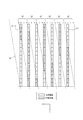
- FIG. 3 is a diagram illustrating a configuration example of the parallax barrier.
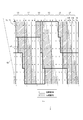
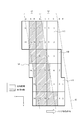
- FIG. 4 is a diagram illustrating a first example of a group of sub-pixels on a display panel.
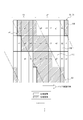
- FIG. 5 is a diagram illustrating switching of the display area in the group of FIG.
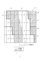
- FIG. 6 is a diagram illustrating switching of the display area in the group of FIG.
- FIG. 7 is a diagram illustrating switching of the display area in the group of FIG.
- FIG. 8 is a diagram illustrating switching of the display area in the group of FIG. FIG.
- FIG. 9 is a diagram illustrating switching of the display area in the group of FIG.
- FIG. 10 is a diagram illustrating switching of the display area in the group of FIG.
- FIG. 11 is a diagram illustrating switching of the display area in the group of FIG.
- FIG. 12 is a diagram illustrating switching of the display area in the group of FIG.
- FIG. 13 is a diagram for explaining a method of determining the switching timing of the R pixel.
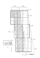
- FIG. 14 is a diagram illustrating a method of determining a barrier tilt angle and a barrier pitch, and sub-pixels included in one group.
- FIG. 15 is a diagram illustrating a second example of a group of sub-pixels on the display panel.
- FIG. 16 is a diagram illustrating a third example of a group of sub-pixels on the display panel.
- FIG. 17 is a schematic configuration diagram of an image display device when the optical element is a lenticular lens.
- FIG. 18 is a schematic configuration diagram of a head-up display (HUD) according to one embodiment.
- FIG. 19 is a diagram showing an example of a vehicle equipped with the HUD shown in FIG.
- a conventional image display device that performs three-dimensional display, a plurality of sub-pixels constituting one pixel have the same length in the horizontal direction.
- the image display device may want to change the area of the sub-pixel for each color. For example, the area of the G (green) sub-pixel having high visibility is made larger than the area of the R (red) and B (blue) sub-pixels to improve the luminous transmittance of the display panel of the image display device. You may want to do that.
- the luminosity is a quantity representing the brightness perceived visually.
- conventionally there has been no method for controlling the images reaching the left and right eyes when the lengths of the sub-pixels in the horizontal direction are different.
- the width of the sub-pixels in the horizontal direction is different, if the control is performed in the same manner as when a display panel having sub-pixels having the same horizontal length is used, the cross-position due to the horizontal position shift of the sub-pixels causes Talk occurs. If the width of the aperture of the parallax barrier is reduced to reduce the crosstalk, the aperture ratio decreases, the visibility decreases, and the image becomes dark.
- An image display device, an image display system, and a head-up display according to the present disclosure described below can appropriately display a three-dimensional image without lowering the brightness of an image when subpixels have different parallax lengths. Can be.
- An image display system 1 according to one of a plurality of embodiments of the present disclosure includes a detection device 2 and an image display device 3, as shown in FIG.
- FIG. 1 shows an image display system 1 viewed from above a user who observes an image with the image display device 3.
- the detection device 2 is configured to detect the position of the left eye (first position) and the position of the right eye (second position) of the user and output the detected position to the image display device 3.
- the detection device 2 may include, for example, a camera.
- the detection device 2 may be configured to be able to photograph a user's face with a camera.
- the detection device 2 may be configured to detect at least one of the left eye position and the right eye position from an image captured by the camera.
- the detection device 2 may be configured to detect at least one position of the left eye and the right eye as coordinates in a three-dimensional space from an image captured by one camera.
- the detection device 2 may be configured to detect at least one position of the left eye and the right eye as coordinates in a three-dimensional space from images captured by two or more cameras.
- the detection device 2 does not have a camera, and may be connected to a camera outside the device.
- the detecting device 2 may include an input terminal for inputting a signal from a camera outside the device.
- a camera outside the device may be directly connected to the input terminal.
- a camera outside the device may be indirectly connected to an input terminal via a network.
- the detection device 2 without a camera may include an input terminal to which the camera inputs a video signal.
- the detection device 2 without a camera may be configured to detect at least one of the left eye position and the right eye position from the video signal input to the input terminal.
- the detection device 2 may include, for example, a sensor.
- the sensor may be an ultrasonic sensor or an optical sensor or the like.
- the detection device 2 may be configured to detect the position of the user's head with a sensor and detect at least one of the left eye and the right eye based on the position of the head.
- the detection device 2 may be configured to detect the position of at least one of the left eye and the right eye as coordinates in a three-dimensional space by one or two or more sensors.
- the detection device 2 When detecting the position of one of the left eye and the right eye, the detection device 2 is configured to estimate the position of the other eye from information on the interocular distance of the user or information on general interocular distance. May be. When the detection device 2 detects the position of one eye and estimates the position of the other eye, it is assumed that the positions of the left eye and the right eye have been detected.
- the image display device 3 includes an irradiator 4, a display panel 5 as a display device, a parallax barrier 6 as an optical element, a controller 7, and an acquisition unit 8.
- the irradiator 4 is arranged on one surface side of the display panel 5 and is configured to irradiate the display panel 5 in a planar manner.
- the irradiator 4 is arranged on the side opposite to the user when viewed from the display panel 5.
- the irradiator 4 may be configured to include a light source, a light guide plate, a diffusion plate, a diffusion sheet, and the like.
- the irradiator 4 is configured to emit irradiation light by a light source and to make the irradiation light uniform in the surface direction of the display panel 5 by a light guide plate, a diffusion plate, a diffusion sheet, or the like.
- the irradiator 4 is configured to emit uniform light toward the display panel 5.
- the display panel 5 may employ a display panel such as a transmissive liquid crystal display panel.
- a display panel such as a transmissive liquid crystal display panel.
- an area of the display panel 5 where an actual image is displayed is called an active area 51.
- the display panel 5 is configured to display various images in the active area 51.
- the active area 51 of the display panel 5 in a space visually perceived by the user is referred to as a display surface 71.
- the display surface 71 It matches the position of the active area 51 of the display panel 5.
- the display surface 71 matches the position of the virtual image of the active area 51 of the display panel 5.
- the user visually captures the active area 51 on the display surface 71 in a space where the display panel 5 does not exist.
- the active area 51 of the display panel 5 includes a plurality of sub-pixels 11 arranged in a lattice along a first direction (x direction) and a second direction (y direction) intersecting the first direction.
- the second direction may be a direction substantially orthogonal to the first direction.
- the display surface 71 coincides with the active area 51.
- the first direction corresponds to a parallax direction that provides parallax to both eyes of the user.
- the first direction can be the horizontal direction viewed from the user.
- the second direction may be a vertical direction viewed from the user.
- the first direction will be described as the x direction and the second direction will be described as the y direction.
- the x direction is shown as a direction from right to left.
- the y direction is shown as a direction from top to bottom.
- a direction orthogonal to the x direction and the y direction and facing the user's eye is defined as a z direction.
- the sub-pixel 11 is longer in the y direction than in the x direction.
- Each sub-pixel 11 corresponds to one of R (red (first color)), G (green (second color)), and B (blue).
- the sub-pixel 11 configured to emit light of each color of R, G, and B will be referred to as a red sub-pixel 11R (first sub-pixel), a green sub-pixel 11G (second sub-pixel), and a blue sub-pixel 11B.
- the ratio of the first length, the second length, and the third length is set to 1: 2: 1.
- the predetermined number of sub-pixels 11 can form a pixel 12.
- the three sub-pixels 11 of the red sub-pixel 11R, the green sub-pixel 11G, and the blue sub-pixel 11B can constitute one pixel 12 as a set. In FIG. 2, for the sake of explanation, some pixels are highlighted by bold lines.
- One pixel 12 can be called one pixel.
- the length of one pixel in the x direction and the length in the y direction can be set to 1: 1 but is not limited thereto.
- the x direction is, for example, a direction in which a plurality of sub-pixels 11 constituting one pixel 12 are arranged.
- the arrangement of the sub-pixels 11 in the x direction is appropriately referred to as “row”.
- the y direction is, for example, a direction in which sub-pixels 11 of the same color are arranged.
- the arrangement of the sub-pixels 11 in the y direction is appropriately referred to as a “column”.
- R, G, and B displayed at the top for the sake of description indicate the colors of the sub-pixels 11 in each column.
- the display panel 5 is not limited to a transmissive display panel, and other display panels such as a self-luminous display panel can be used.
- the transmissive display panel includes a MEMS (Micro Electro Mechanical Systems) shutter type display panel in addition to the liquid crystal panel.
- Self-luminous display panels include organic EL (electro-luminescence) and inorganic EL display panels. When a self-luminous display panel is used as the display panel 5, the irradiator 4 becomes unnecessary.
- the parallax barrier 6 is an optical element configured to regulate the light beam direction of image light emitted from each sub-pixel 11 of the display panel 5.
- the parallax barrier 6 has, for example, a plurality of dimming regions 61 (optical elements) and a plurality of translucent regions 62, as shown in FIG.
- the plurality of light-reducing regions 61 and the plurality of light-transmitting regions 62 may have a band shape (slit shape) extending in a predetermined direction.
- the dimming region 61 and the light transmitting region 62 of the parallax barrier 6 are arranged to face the display panel 5.
- the plurality of light reducing regions 61 and the plurality of light transmitting regions 62 can be alternately arranged along the x direction.
- the plurality of dimming regions 61 have widths substantially equal to each other and are periodically arranged in the x direction.
- the plurality of translucent regions 62 have a width substantially equal to each other and are periodically arranged in the x direction.
- the width of the light transmitting region 62 in the x direction can be equal to or smaller than the width of the light reducing region 61 in the x direction. In the following description, it is assumed that the width of the light transmitting region 62 in the x direction is equal to the width of the light reducing region 61 in the x direction. In this case, the barrier aperture ratio of the parallax barrier 6 is 50%.
- the barrier aperture ratio is the width of the parallax barrier 6 in the x direction (that is, the sum of the width of the dimming region 61 in the x direction and the width of the translucent region 62 in the x direction). Is the ratio of If the barrier aperture ratio is narrow, the image becomes dark.
- the image light emitted from the sub-pixel 11 defines a range that can be visually recognized by the left eye and the right eye by the parallax barrier 6.
- the parallax barrier 6 can be located on the opposite side of the illuminator 4 with respect to the display panel 5, as shown in FIG. In another embodiment, the parallax barrier 6 can be located on the illuminator 4 side of the display panel 5.
- the light transmitting region 62 is a portion that transmits light incident on the parallax barrier 6.
- the light transmitting region 62 may transmit light with a transmittance equal to or higher than a first predetermined value.
- the first predetermined value may be, for example, approximately 100%, or may be a value less than 100%. If the image light emitted from the active area 51 is within a range in which the image light can be visually recognized well, the first predetermined value may be a value of 100% or less, for example, 80% or 50%.
- the dimming region 61 is a portion that diminishes light incident on the parallax barrier 6 and hardly transmits the light.
- the dimming region 61 significantly reduces the rate at which the image light emitted from the image displayed in the active area 51 of the display panel 5 reaches the user's eyes, or effectively blocks the light. Be composed.
- the dimming region 61 may block light with a transmittance equal to or less than a second predetermined value.
- the second predetermined value may be, for example, approximately 0%, greater than 0%, and a value close to 0%, such as 0.5%, 1%, or 3%.
- the first predetermined value may be several times or more, for example, 10 times or more, or 100 times or more larger than the second predetermined value.
- the light transmitting regions 62 and the light reducing regions 61 are alternately arranged in a direction along the xy plane.
- a line indicating the boundary between the light-reducing region 61 and the light-transmitting region 62 extends in a direction inclined at a predetermined angle ⁇ with respect to the y direction.
- the line indicating the boundary between the light reduction region 61 and the light transmission region 62 is also referred to as the boundary line between the light reduction region 61 and the light transmission region 62.
- the predetermined angle ⁇ is also called a barrier inclination angle.
- the barrier inclination angle ⁇ may be an angle larger than 0 degrees and smaller than 90 degrees.
- the parallax barrier 6 may be formed of a film or a plate-like member having a transmittance smaller than the second predetermined value.
- the dimming region 61 is configured by the film or the plate-like member.
- the light transmitting region 62 is configured by an opening provided in a film or a plate-like member.
- the film may be made of a resin or may be made of another material.
- the plate member may be made of resin, metal, or the like, or may be made of another material.
- the parallax barrier 6 is not limited to a film or a plate-shaped member, and may be formed of another type of member.
- the parallax barrier 6 may be composed of a light-reducing base material.
- the parallax barrier 6 may be composed of a base material containing an additive having a dimming property.
- the parallax barrier 6 may have a configuration in which a member having a light-reducing property partially overlaps a base material having a light-transmitting property.
- the parallax barrier 6 may have a configuration in which a member having a light reducing property is added to a part of a base material having a light transmitting property.
- the parallax barrier 6 may be constituted by a liquid crystal shutter.
- the liquid crystal shutter is configured to be able to control the light transmittance in accordance with the applied voltage.
- the liquid crystal shutter may be composed of a plurality of pixels, and control the light transmittance of each pixel. In the liquid crystal shutter, a region having a high light transmittance or a region having a low light transmittance may be formed in an arbitrary shape.
- the light transmitting region 62 may be a region having a transmittance equal to or higher than a first predetermined value.
- the dimming region 61 may be a region having a transmittance equal to or less than a second predetermined value.
- the parallax barrier 6 includes a shutter panel configured to be variable between a light-transmitting state and a dimming state for each minute area.
- the shutter panel includes a MEMS (Micro Electro Mechanical System) shutter panel employing a MEMS shutter panel in addition to the liquid crystal shutter.
- MEMS Micro Electro Mechanical System
- the controller 7 is connected to each component of the image display system 1 and is configured to control each component.
- the controller 7 is configured as, for example, a processor.
- Controller 7 may include one or more processors.
- the processor may include a general-purpose processor that executes a specific function by reading a specific program, and a dedicated processor specialized for a specific process.
- the dedicated processor may include an application specific integrated circuit (ASIC: Application Specific Integrated Circuit).
- the processor may include a programmable logic device (PLD: Programmable Logic Device).
- the PLD may include an FPGA (Field-Programmable ⁇ Gate ⁇ Array).
- the controller 7 may be any one of an SoC (System-on-a-Chip) in which one or a plurality of processors cooperate, and a SiP (System ⁇ In ⁇ a ⁇ Package).
- the controller 7 includes a storage unit, and may store various information, a program for operating each component of the image display system 1, and the like in the storage unit.
- the storage unit may be composed of, for example, a semiconductor memory or the like.
- the storage unit may function as a work memory of the controller 7.
- the acquisition unit 8 is configured to acquire information on the position of the left eye and the position of the right eye from the detection device 2 and deliver the information to the controller 7.
- the acquisition unit 8 includes an input terminal that receives an input from the detection device 2.
- the input terminals include an electrical connector that supports transmission by an electric signal and an optical connector that supports transmission by an optical signal.
- the controller 7 is configured to control an image displayed for each sub-pixel 11 included in the plurality of sub-pixels 11 of the display panel 5 based on the position of the left eye and the position of the right eye acquired by the acquisition unit 8. Is done.
- an image display method by the controller 7 will be described.
- FIG. 4 A method of displaying a three-dimensional image on the active area 51 of the display panel 5 will be described with reference to FIG.
- the outline 63 of the parallax barrier 6 viewed from the left eye (first eye) of the user is shown by a two-dot chain line on the active area 51 for explanation. That is, the outline 63 of the parallax barrier 6 shown in FIG. 4 is obtained by projecting the parallax barrier 6 onto the active area 51 from a point of an appropriate viewing distance at which the left eye of the user is arranged.
- projection means connecting all points on an object from a certain reference point outside the target object by straight lines along the optical path, and forming the intersection of these straight lines and the plane on which the object is projected. Means the figure to be drawn. “Project” means that the projection of the object is formed on a plane. When there is an optical element such as a lens or a mirror between the reference point and the plane on which the object is projected, a straight line connecting the reference point and a point on the object receives refraction, deflection, and the like due to the optical effect of the optical element. It shall be along the optical path.
- the image light emitted from the active area 51 of the display panel 5 and transmitted through the light transmitting area 62 of the parallax barrier 6 reaches the user's eyes.
- the left eye of the user can visually recognize the first region 52 on the active area 51 as a band-shaped region corresponding to the light-transmitting region 62.
- the image light emitted from the second area 53 on the active area 51 corresponding to the dimming area 61 of the parallax barrier 6 is dimmed before reaching the left eye of the user.
- the left eye of the user hardly sees the second area 53 on the active area 51 corresponding to the dimming area 61.
- the image display system 1 when viewed from the right eye (second eye) of the user, the user, via the translucent area 62, The two regions 53 can be visually recognized. The image light is blocked by the dimming region 61 of the parallax barrier 6, so that the right eye of the user cannot see the first region 52 on the active area 51.
- the user's view is recognized as a three-dimensional image. Images can be displayed.
- an image to be projected to the left eye is referred to as a left-eye image (first image)
- an image to be projected to the right eye is referred to as a right-eye image (second image).
- the plurality of translucent regions 62 of the parallax barrier 6 are configured to transmit the left-eye image displayed in the first region 52 in the direction of the optical path toward the left eye of the user.
- the plurality of translucent areas 62 of the parallax barrier 6 are configured to transmit the right-eye image displayed in the second area 53 in the direction of the optical path toward the right eye of the user.
- the controller 7 switches the image displayed for each sub-pixel 11 between the left-eye image and the right-eye image according to the positions of the left and right eyes of the user and the configurations of the display panel 5 and the parallax barrier 6. Is composed of The controller 7 displays an image displayed for each sub-pixel 11 according to the position of the left and right eyes of the user and the configuration of the display panel 5 and the parallax barrier 6 in either a left-eye image or a right-eye image. Is configured to determine. The controller 7 is configured to be able to determine a sub-pixel 11 that displays a left-eye image and a sub-pixel 11 that displays a right-eye image from among the plurality of sub-pixels 11.
- the sub-pixels 11 entirely belonging to the first area 52 are controlled to display a left-eye image.
- the sub-pixels 11 entirely belonging to the second area 53 are controlled to display a right-eye image. If the sub-pixels 11 partially belong to the first region 52 and partially belong to the second region 53, the left-eye image is displayed when the sub-pixels 11 overlap the first region 52 more than the second region 53. Is controlled as follows. If the sub-pixels 11 partially belong to the first area 52 and partially belong to the second area 53, the sub-pixels 11 overlap the second area 53 more than the first area 52, and display a right-eye image. Is controlled as follows.
- the controller 7 is configured to control a plurality of sub-pixels 11 belonging to the same group 54 as one control unit.
- the group 54 is a minimum group of a plurality of sub-pixels 11 having the same arrangement pattern of the sub-pixel 11 displaying the left-eye image and the sub-pixel 11 displaying the right-eye image.
- the controller 7 is configured so that the whole image can be regularly reconstructed by repeatedly arranging the sub-pixels 11 of the group 54 arranged in the same arrangement pattern two-dimensionally on the active area 51. Is done.
- the display of the left-eye image and the right-eye image of each sub-pixel 11 can be controlled based on the group 54.
- One group 54 includes a plurality of sub-pixels 11.
- the sub-pixels 11 for displaying the left-eye image and the sub-pixels 11 for displaying the right-eye image are arranged in the same positional relationship between different groups.
- a red subpixel 11R, a green subpixel 11G, and a blue subpixel 11B are arranged in the same positional relationship.
- the plurality of groups 54 are arranged with periodicity in the x direction and the y direction.
- the controller 7 is configured to be able to determine the sub-pixel 11 for displaying the left-eye image and the sub-pixel 11 for displaying the right-eye image in the same arrangement pattern for the sub-pixel groups of all the groups 54. .
- the controller 7 is configured to simultaneously switch the display of the sub-pixels 11 located at the corresponding positions between the left-eye image and the right-eye image in all the groups 54.
- a first example of an arrangement method of the sub-pixels 11 for displaying the left-eye image and the sub-pixels 11 for displaying the right-eye image according to one embodiment will be described with reference to FIG.
- each of the sub-pixels 11 included in the same group 54 is numbered 1 to 14 for the red, green, and blue sub-pixels 11R, 11G, and 11B, respectively.
- the colors of the pixels are indicated by the symbols R, G, and B at the top of the column of each sub-pixel 11 as in FIG.
- R, G, and B at the top of the column of each sub-pixel 11 as in FIG.
- the individual red sub-pixels 11R of each group 54 are preceded by “r” to distinguish them from the sub-pixels 11 of other colors, and Description will be given as a pixel 11R.
- the green sub-pixel 11G will be described as a green sub-pixel 11G of a number g1 to g14 with “g” added before the number.
- the blue sub-pixel 11B will be described as a blue sub-pixel 11B of a number b1 to b14 with “b” added before the number.
- FIG. 4 is a diagram illustrating a state when the user's eyes are located at the reference position with respect to the display panel 5.
- Each of the sub-pixels 11 with numbers r1 to r7, g1 to g7, and b1 to g7 in FIG. 4 displays a left-eye image because more than half of the region belongs to the first region 52.
- Each of the sub-pixels 11 with numbers r8 to r14, g8 to g14, and b8 to b14 in FIG. 4 displays a right-eye image because more than half of the region belongs to the second region 53.
- the sub-pixels 11 for displaying the left-eye image are shown without shading.
- the sub-pixels 11 for displaying the right-eye image are shaded in the figure.
- the group 54 extends over an array (rows) of the plurality of sub-pixels 11 arranged in the x direction and an array (columns) of the plurality of sub-pixels 11 arranged in the y direction on the active area 51.
- the group of sub-pixels in group 54 extends into a plurality of rows and a plurality of columns.
- the sub-pixel groups of the adjacent group 54 are shifted from each other in the x direction and the y direction.
- the controller 7 of FIG. 1 displays an image to be displayed on the sub-pixels 11 belonging to the group 54 according to the position of both eyes of the user detected by the detection device 2 in one of a left-eye image and a right-eye image. Is determined.
- the red sub-pixel 11R of numbers r1 to r7, the green sub-pixel 11G of numbers g1 to g7, and the blue sub-pixel 11B of numbers b1 to b7 are the sub-pixels 11 for displaying the left eye image.
- the red sub-pixel 11R of numbers r8 to r14, the green sub-pixel 11G of numbers g8 to g14, and the blue sub-pixel 11B of numbers b8 to b14 are the sub-pixels 11 for displaying the right-eye image.
- FIGS. 5 to 12 show the case where the position of the parallax barrier 6 viewed from the user's eye located at an appropriate viewing distance is sequentially displaced from the position of FIG. 4 to the negative side (the direction of the arrow) in the x direction.
- FIG. 9 is a diagram illustrating a change in an image displayed by each sub-pixel 11 of a group 54. 5 to 12, the position of the parallax barrier 6 is indicated by a contour 63 of the parallax barrier 6.
- Such displacement of the parallax barrier 6 may occur when the user's eyes move to the left relative to the image display device 3. With the displacement of the outline 63, the first region 52 and the second region 53 sandwiched between the outlines 63 are displaced.
- FIG. 5 shows an arrangement of sub-pixels 11 for displaying a left-eye image and a right-eye image when the left eye and the right eye of the user are located at the same reference position as in FIG.
- FIG. 6 shows a state where the position of the parallax barrier 6 viewed from the user's eyes is displaced from the state of FIG.
- the image displayed by the red sub-pixel 11R of the number r7 is changed from the left-eye image to the right-eye image.
- the image displayed by the red sub-pixel 11R of the number r14 changes from the right-eye image to the left-eye image.
- the display switching between the right-eye image and the left-eye image is performed between the red sub-pixels 11R of the numbers r7 and r14.
- the position of the parallax barrier 6 viewed from the user's eyes is further displaced to the negative side in the x direction (the direction of the arrow). Accordingly, as shown in FIG. 7, the image displayed by the green sub-pixel 11G of the number g7 is changed from the left-eye image to the right-eye image. At the same timing as the image displayed by the green sub-pixel 11G of the number g7 changes, the image displayed by the green sub-pixel 11G of the number g14 changes from the right-eye image to the left-eye image. Further, as shown in FIG. 8, the image displayed by the blue sub-pixel 11B of the number b7 is changed from the left-eye image to the right-eye image. At the same timing as the image displayed by the blue sub-pixel 11B of the number b7 changes, the image displayed by the blue sub-pixel 11B of the number b14 changes from the right-eye image to the left-eye image.
- the position of the parallax barrier 6 is further displaced sequentially to the negative side in the x direction. Accordingly, first, as shown in FIG. 9, display switching between the left-eye image and the right-eye image is performed between the two red sub-pixels 11R of numbers r6 and r13. Next, as shown in FIG. 10, the display of the left-eye image and the display of the right-eye image are switched between the two green sub-pixels 11G with the numbers g6 and g13. Further, as shown in FIG. 11, the display switching between the left-eye image and the right-eye image is performed between the two blue sub-pixels 11B of the numbers b6 and b13.
- FIG. 12 shows a state in which the parallax barrier 6 is further displaced.
- the display of the left-eye image and the right-eye image is sequentially switched between the red sub-pixel 11R of numbers r5 and r12, the green sub-pixel 11G of numbers g5 and g12, and the blue sub-pixel 11B of numbers b5 and b12. Be done. Further, when the parallax barrier 6 is displaced, the display image is similarly switched between the sub-pixels. Thereby, even if the position of the user's eyes changes, the display panel 5 can continue to display the stereoscopic image to the user.
- the controller 7 is configured to control the plurality of sub-pixels 11 including the red sub-pixel 11R, the green sub-pixel 11G, and the blue sub-pixel 11B included in the group 54 as the group 54.
- the controller 7 displays the image displayed by another red sub-pixel 11R belonging to the same group 54. Is changed from the right-eye image to the left-eye image. The same applies when changing the images displayed by the green sub-pixel 11G and the blue sub-pixel 11B.
- the controller 7 is configured to switch the sub-pixels 11 indicated by the same number between the left-eye image and the right-eye image at the same timing in all the groups 54.
- the first timing at which the controller 7 changes the image displayed by the red sub-pixel 11R between the left-eye image and the right-eye image is determined by changing the image displayed by the green sub-pixel 11G to the right-eye image and the right-eye image. This may be different from the second timing for changing between the eye image and the eye image. Further, the third timing for changing the image displayed by the blue sub-pixel 11B between the left-eye image and the right-eye image may be different from the first timing and the second timing.
- the widths in the x direction of the red subpixel 11R, the green subpixel 11G, and the blue subpixel 11B are not equal.
- the positions where the display images of the red sub-pixel 11R, the green sub-pixel 11G, and the blue sub-pixel 11B are switched with respect to the apparent displacement of the parallax barrier 6 are not the same.
- the apparent displacement of the parallax barrier 6 corresponds to the displacement of the user's head.
- the red sub-pixels 11R are arranged at equal intervals in the x-direction at a pitch of one pixel. Therefore, the red sub-pixel 11R can be controlled based on the displacement of the user's head from the switching origin, based on the switching origin independent of the green sub-pixel 11G and the blue sub-pixel 11B. The same applies to the green sub-pixel 11G and the blue sub-pixel 11B.
- the switching origin can be adjusted for each color of the sub-pixel 11.
- a method of adjusting the switching origin of the red sub-pixel 11R will be described with reference to FIG.
- the controller 7 displays all the green sub-pixels 11G and the blue sub-pixels 11B in black.
- the black display is a display of a gradation with the lowest luminance of the sub-pixel 11.
- the outline of the sub-pixel 11 in the black display is indicated by a broken line.
- an image for the left eye is displayed on the red sub-pixels 11R of numbers r2 to r7
- an image for the right eye is displayed on the red sub-pixels 11R of numbers r9 to r14.
- the user switches the images displayed on the red sub-pixel 11R of the number r1 and the red sub-pixel 11R of the number r8 between the left-eye image and the right-eye image,
- the position of the head is adjusted in the x direction.
- a position where no change is observed in the displayed image can be set as the reference position.
- the user can adjust the reference positions of the green sub-pixel 11G and the blue sub-pixel 11B while the other color sub-pixels 11 are displayed in black.
- the information on the reference position can be stored in the storage unit of the controller 7.
- the controller 7 performs independent switching control between the left-eye image and the right-eye image based on each switching origin for each of the red subpixel 11R, the green subpixel 11G, and the blue subpixel 11B. It is configured to be able to. Accordingly, regardless of the difference in the length of the red sub-pixel 11R, the green sub-pixel 11G, and the blue sub-pixel 11B along the x direction, the image displayed on the sub-pixel 11 is set between the left-eye image and the right-eye image. It is possible to switch with.
- the controller 7 sets the 14 red sub-pixels 11R, the green sub-pixel 11G, and the blue sub-pixel 11B as one group 54, and displays the image displayed on each sub-pixel 11 with the left-eye image and the right-eye image. Switching processing was performed between eye images.
- the image display device 3 of the present disclosure can employ the configuration of the group 54 having the arrangement pattern of the other sub-pixels 11 and the configuration of the parallax barrier 6 corresponding to the group 54.
- a method of designing the parallax barrier 6 and a method of arranging the sub-pixels 11 of the group 54 will be described with reference to FIG.
- the pitch in the x direction (horizontal pitch) of the pixels 12 on the active area 51 is Hp
- the pitch in the y direction (vertical pitch) is Vp
- the barrier inclination angle of the parallax barrier 6 projected on the active area 51 is ⁇
- the active area is The image pitch on 51 is k.
- the barrier inclination angle ⁇ is the inclination angle of the parallax barrier 6 projected onto the active area 51 from the position of the user's eye located at an appropriate viewing distance. More specifically, the barrier inclination angle ⁇ is the angle of the direction in which the projection of the light transmitting area 62 and the light reducing area 61 on the active area 51 extends with respect to the y direction.
- the image pitch k is an x-direction pitch of the dimming area 61 and the light transmitting area 62 of the parallax barrier 6 projected onto the active area 51 from a point of an appropriate viewing distance where the user's eyes are arranged.
- the image pitch k is equal to the width in the x direction of the combined area of the adjacent first area 52 and second area 53.
- the barrier inclination angle ⁇ is such that the contour 63 indicating the boundary between the light-reducing area 61 and the light-transmitting area 62 of the parallax barrier 6 projected on the active area 51 crosses a natural number a of horizontal pitches Hp. It is set so as to cross the natural number b vertical pitches Vp in between. That is, the barrier inclination angle ⁇ (the third direction) is a direction in which the pixel advances by a pixel in the x direction and a pixel advances by b pixels in the y direction.
- a and b a combination of integers other than 0 that are relatively prime can be adopted.
- the image pitch k is determined by setting the horizontal distance between the straight lines to half of the image pitch k.
- two straight lines having the barrier inclination angle ⁇ pass through the two vertices A and B.
- k 8Hp / 3.
- the two vertices A and B can be arbitrarily selected. For example, in FIG. 14, instead of a straight line passing through the vertex B, a straight line passing through the vertex C or the vertex D may be selected.
- the number of pixels included in one group 54 is calculated based on the image pitch k.
- the number 2n of pixels included in the group 54 and the image pitch k have a relationship represented by the following equation (2).
- 2n is equal to the number of sub-pixels 11 of each color included in the group 54.
- 2n is 8.
- 2n is 14.
- the sub-pixels 11 included in the group 54 are arranged on two straight lines having an inclination of the barrier inclination angle ⁇ and between the two straight lines, and are arranged in a range of a height of b pixels in the vertical direction. be able to.
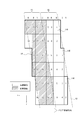
- FIG. 15 shows a group 54 of the sub-pixels 11 according to the second example.
- the red sub-pixel 11R of numbers r1 to r3, the green sub-pixel 11G of numbers g1 to g3, and the blue sub-pixel 11B of numbers b1 to b3 display the left eye image.
- the red sub-pixel 11R of numbers r4 to r6, the green sub-pixel 11G of numbers g4 to g6, and the blue sub-pixel 11B of numbers b4 to b6 display the image for the right eye.
- the controller 7 sets the left eye between the green sub-pixel 11G of number g6 and the green sub-pixel 11G of number g3. Switching between the image and the right eye image is performed. Next, the controller 7 controls the left-eye image and the right-eye image between the red subpixel 11R of number r6 and the red subpixel 11R of number r3, and the blue subpixel 11B of number b6 and the blue subpixel 11B of number b3. Switch the display with the image. Similarly, the image displayed by each of the two sub-pixels 11 of the same color is sequentially switched between the left-eye image and the right-eye image.
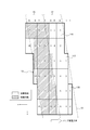
- FIG. 16 shows a group 54 of the sub-pixels 11 according to the third example.
- a red sub-pixel 11R of numbers r1 to r5 a green sub-pixel 11G of numbers g1 to g5, and a blue sub-pixel 11B of numbers b1 to b5 display an image for the left eye.
- the red sub-pixel 11R of numbers r6 to r10, the green sub-pixel 11G of numbers g6 to g10, and the blue sub-pixel 11B of numbers b6 to b10 display the right-eye image.
- the controller 7 sets the left eye between the green sub-pixel 11G of the number g10 and the green sub-pixel 11G of the number g5. Switching between the image and the right eye image is performed. Next, the controller 7 controls the left-eye image and the right-eye image between the red sub-pixel 11R of number r10 and the red sub-pixel 11R of number r5, and the blue sub-pixel 11B of number b10 and the blue sub-pixel 11B of number b5. Replace with image. Similarly, the images displayed by the two sub-pixels 11 of the same color are sequentially switched between the left-eye image and the right-eye image.
- the controller 7 is displayed on the sub-pixel 11 while using the display panel 5 in which the length of the sub-pixel 11 in the parallax direction is different.
- the image for the right eye and the image for the left eye can be appropriately switched.
- the occurrence of crosstalk can be reduced while maintaining a high aperture ratio, so that a three-dimensional image can be appropriately displayed without lowering the brightness of the image.
- the user of the image display system 1 and the image display device 3 can appropriately view the three-dimensional image.
- the parallax barrier 6 As an optical element configured to regulate the light beam direction of the image displayed on the display panel 5, a three-dimensional image can be displayed with a simple configuration. Further, since the dimming region 61 of the parallax barrier 6 extends in an oblique direction intersecting the x direction and the y direction, it is possible to reduce the occurrence of moire.
- the controller 7 is configured to change the left-eye image and the right-eye image at different timings for each of the colors R, G, and B.
- the controller 7 is configured to adjust the switching origin for each of the R, G, and B colors, and to control the switching timing independently for each of the colors. Accordingly, it is possible to switch the image displayed by the sub-pixel 11 at an appropriate timing, corresponding to various lengths in the x direction that are different for each color of the sub-pixel 11.
- the design method of the present disclosure can appropriately determine the group 54 of the sub-pixels 11 controlled by the parallax barrier 6 and the controller 7 when using the display panel 5 in which the lengths of the sub-pixels 11 in the parallax direction are different.
- the design method of the present disclosure can design the image display system 1 and the image display device 3 that realize three-dimensional image display.
- the image display system 1 and the image display device 3 can set the image pitch k to various values. Thereby, the degree of freedom of design of the image display system 1 and the image display device 3 increases.
- FIG. 17 shows an image display system 1A according to one of the plurality of embodiments. 17, components that are the same as or similar to the image display system 1 of FIG. 1 are given the same reference numerals, and descriptions thereof will be omitted.
- the image display device 3 has the parallax barrier 6 as an optical element.
- the image display device 3A of the image display system 1A can have a lenticular lens 9 instead of the parallax barrier 6 as an optical element.
- the lenticular lens 9 can be configured by arranging fine elongated semi-cylindrical cylindrical lenses 10 that extend obliquely with respect to the x direction and the y direction.
- the image display system 1A shown in FIG. 17 is of a type in which the user looks directly at the display panel 5. For this reason, the display surface 71 in the space visually perceived by the user matches the active area 51.
- the areas on the active area 51 of the display panel 5 configured to be visible from the left and right eyes of the user located at the appropriate viewing distance can be the first area 52 and the second area 53, respectively.
- the lenticular lens 9 is configured to deflect the image light of the left eye image emitted from the first area 52 of the display panel 5 toward the left eye of the user.
- the lenticular lens 9 is configured to deflect the image light of the right eye image emitted from the second area 53 of the display panel 5 toward the right eye of the user located at an appropriate viewing distance.
- the lenticular lens 9 is an optical element configured to regulate the light beam direction of an image displayed on the display panel 5.
- the display positions of the sub-pixels 11 of the left-eye image and the right-eye image on the active area 51 take into account the effects of refraction and deflection of image light by the respective cylindrical lenses 10 of the lenticular lens 9.
- the display panel 5 has a different length along the x direction for each color.
- the controller 7 controls the display switching of the left-eye image and the right-eye image of each sub-pixel 11 similarly to the case where the parallax barrier 6 is used. can do. That is, the image display system 1A and the image display device 3A appropriately display a three-dimensional image without reducing the brightness of the image while using the display panel 5 in which the length of the sub-pixel 11 in the x direction is different for each color. It becomes possible to do.
- the image display system 1B can be mounted on the head-up display 100.
- the image display system 1B has the same or similar configuration as the image display system 1 of FIG. 1 except that the user does not look directly at the display panel 5.
- the image display system 1B includes an image display device 3 and a detection device 2. Components of the image display system 1B that are the same as or similar to the image display system 1 are denoted by the same reference numerals as those of the image display system 1, and description thereof is omitted.
- the head-up display 100 is also called a HUD (Head Up Display).
- the HUD 100 includes an image display system 1B, one or more optical members 110, and a projection member 120 having a projection surface 130.
- the optical member 110 and the projection target member 120 are included in an optical system that projects an image displayed in the active area 51 so as to form a virtual image on a user's visual field.
- the optical member 110 and the projection target member 120 may be collectively referred to simply as an optical system.
- the optical member 110 and the projection target member 120 may be reflective optical members that reflect image light of a display image.
- the optical member 110 and the projection target member 120 may have a concave or convex reflecting surface.
- the HUD 100 is configured to cause the image light emitted from the image display system 1B to reach the projection surface 130 of the projection member 120 via the optical member 110.
- the HUD 100 is configured to cause the image light reflected on the projection surface 130 to reach the left and right eyes of the user. That is, the HUD 100 is configured to cause the image light to travel from the image display system 1 to the left and right eyes of the user along the optical path 140 indicated by the broken line. The user can visually recognize the image light that has arrived along the optical path 140 as a virtual image 150.
- the image display system 1 ⁇ / b> B is configured so that the detection device 2 detects the positions of the left eye and the right eye of the user.
- the controller 7 of the image display device 3 controls the image displayed on the display panel 5 according to the detected positions of the left eye and the right eye, thereby providing an image visually recognized as a stereoscopic image by the user. It is configured as follows.
- the display surface 71 is located at the position where the virtual image 150 is displayed.
- the position where the virtual image 150 is displayed is a position where the user visually recognizes the image displayed in the active area 51 as a virtual image.
- the HUD 100 may be mounted on a moving body 200 such as a vehicle.
- the HUD 100 may share a part of the configuration with other devices and components included in the moving body 200.
- the HUD 100 may use the windshield of the moving body 200 as the projected member 120 of the HUD 100.
- the HUD 100 of the present disclosure appropriately displays a three-dimensional image without reducing the brightness of the image while using the display panel 5 in which the length of the sub-pixel 11 in the parallax direction is different. can do. As a result, the HUD 100 can display a bright image even when the HUD 100 is mounted on the moving body 200 and the windshield is the projection target member 120.
- ⁇ “ Moving object ”in the present disclosure includes vehicles, ships, and aircraft.
- the “vehicle” in the present disclosure includes, but is not limited to, automobiles and industrial vehicles, and may include railway vehicles, domestic vehicles, and fixed-wing aircraft traveling on a runway.
- Automobiles include, but are not limited to, passenger cars, trucks, buses, motorcycles, trolleybuses, and the like, and may include other vehicles traveling on roads.
- Industrial vehicles include industrial vehicles for agriculture and construction.
- Industrial vehicles include, but are not limited to, forklifts and golf carts.
- Industrial vehicles for agriculture include, but are not limited to, tractors, tillers, transplanters, binders, combines, and lawnmowers.
- Industrial vehicles for construction include, but are not limited to, bulldozers, scrapers, excavators, crane trucks, dump trucks, and road rollers. Vehicles include those that run manually.
- the classification of the vehicle is not limited to the above.
- an automobile may include an industrial vehicle that can travel on a road, and a plurality of classifications may include the same vehicle.
- Ships in the present disclosure include marine jets, boats, and tankers.
- the aircraft according to the present disclosure includes a fixed wing aircraft and a rotary wing aircraft.
- descriptions such as “first” and “second” are identifiers for distinguishing the configuration.
- the numbers in the configurations can be exchanged.
- the identifiers “first” and “second” can be exchanged with the second direction.
- red is the first color
- green is the second color.
- the first and second colors may be arbitrarily replaced between red, blue and green. The same applies to the first sub-pixel and the second sub-pixel.
- the first eye and the second eye are the left eye and the right eye, respectively, but the first eye may be the right eye and the second eye may be the left eye.
- the exchange of identifiers takes place simultaneously. Even after the exchange of the identifier, the configuration is distinguished.
- the identifier may be deleted.
- the configuration from which the identifier is deleted is distinguished by a code. Interpretation of the order of the configuration, grounds for the existence of a small-numbered identifier, grounds for the existence of a large-numbered identifier based only on the description of identifiers such as “first” and “second” in the present disclosure Must not be used for
- the width in the x direction of the light-reducing region 61 and the light-transmitting region 62 of the parallax barrier 6 is the same. That is, the barrier aperture ratio of the parallax barrier 6 is 50%. In this case, the left eye of the user can visually recognize the entire first region 52. Further, the right eye of the user can visually recognize the entire second region 53.
- the barrier aperture ratio of the image display device 3 is not limited to 50%.
- the width of the light transmitting region 62 in the x direction can be made smaller than the width of the light reducing region 61 in the x direction.
- Crosstalk is a phenomenon in which a part of the left-eye image enters the right eye of the user and / or a part of the right-eye image enters the left eye of the user.
- the width of the light transmitting region 62 in the x direction is smaller than the width of the light reducing region 61 in the x direction, crosstalk can be reduced. In that case, the barrier aperture ratio is smaller than 50%.
Landscapes
- Engineering & Computer Science (AREA)
- Physics & Mathematics (AREA)
- Multimedia (AREA)
- Signal Processing (AREA)
- Chemical & Material Sciences (AREA)
- Combustion & Propulsion (AREA)
- Transportation (AREA)
- Mechanical Engineering (AREA)
- Optics & Photonics (AREA)
- General Physics & Mathematics (AREA)
- Testing, Inspecting, Measuring Of Stereoscopic Televisions And Televisions (AREA)
- Controls And Circuits For Display Device (AREA)
Abstract
Ce dispositif d'affichage d'image est pourvu d'un panneau d'affichage, d'un élément optique, d'une unité d'acquisition et d'un dispositif de commande. Le dispositif de commande est configuré pour pouvoir commuter, entre une image d'œil gauche et une image d'œil droit, une image affichée sur un sous-pixel. Le panneau d'affichage comprend des sous-pixels rouges et verts ayant des largeurs différentes dans une direction x. Le dispositif de commande est configuré pour commander une pluralité de sous-pixels en tant que groupe, et est également configuré de telle sorte que lorsqu'une image affichée par un sous-pixel rouge appartenant à un groupe est changée d'une image d'œil gauche à une image d'œil droit, une image affichée par un autre sous-pixel rouge appartenant au même groupe est changée d'une image d'œil gauche à une image d'œil droit.
Priority Applications (4)
| Application Number | Priority Date | Filing Date | Title |
|---|---|---|---|
| CN201980041389.5A CN112335235B (zh) | 2018-06-26 | 2019-06-21 | 图像显示装置、图像显示系统、平视显示器、移动体及图像显示方法 |
| JP2020527484A JP7119086B2 (ja) | 2018-06-26 | 2019-06-21 | 画像表示装置、画像表示システム、ヘッドアップディスプレイ、移動体および画像表示方法 |
| EP19825958.2A EP3817380A4 (fr) | 2018-06-26 | 2019-06-21 | Dispositif d'affichage d'images, système d'affichage d'images, affichage tête haute, corps mobile et procédé d'affichage d'images |
| US17/255,165 US11307427B2 (en) | 2018-06-26 | 2019-06-21 | Image display device, image display system, head-up display, moving body, and image display method |
Applications Claiming Priority (2)
| Application Number | Priority Date | Filing Date | Title |
|---|---|---|---|
| JP2018121077 | 2018-06-26 | ||
| JP2018-121077 | 2018-06-26 |
Publications (1)
| Publication Number | Publication Date |
|---|---|
| WO2020004276A1 true WO2020004276A1 (fr) | 2020-01-02 |
Family
ID=68986899
Family Applications (1)
| Application Number | Title | Priority Date | Filing Date |
|---|---|---|---|
| PCT/JP2019/024778 Ceased WO2020004276A1 (fr) | 2018-06-26 | 2019-06-21 | Dispositif d'affichage d'images, système d'affichage d'images, affichage tête haute, corps mobile et procédé d'affichage d'images |
Country Status (5)
| Country | Link |
|---|---|
| US (1) | US11307427B2 (fr) |
| EP (1) | EP3817380A4 (fr) |
| JP (1) | JP7119086B2 (fr) |
| CN (1) | CN112335235B (fr) |
| WO (1) | WO2020004276A1 (fr) |
Cited By (3)
| Publication number | Priority date | Publication date | Assignee | Title |
|---|---|---|---|---|
| WO2022065355A1 (fr) * | 2020-09-28 | 2022-03-31 | 京セラ株式会社 | Dispositif d'affichage tridimensionnel, procédé d'affichage tridimensionnel, système d'affichage tridimensionnel et objet mobile |
| WO2023100956A1 (fr) * | 2021-11-30 | 2023-06-08 | 京セラ株式会社 | Dispositif d'affichage tridimensionnel, système d'affichage tridimensionnel et objet mobile |
| WO2024021852A1 (fr) * | 2022-07-27 | 2024-02-01 | 华为技术有限公司 | Appareil d'affichage stéréoscopique, système d'affichage stéréoscopique et véhicule |
Families Citing this family (2)
| Publication number | Priority date | Publication date | Assignee | Title |
|---|---|---|---|---|
| KR102061715B1 (ko) * | 2019-06-05 | 2020-01-02 | 정종필 | 내화학성을 갖는 실험대 상판 제조방법 |
| CN113917699B (zh) * | 2021-11-02 | 2024-01-05 | 合肥京东方卓印科技有限公司 | 三维显示面板及其控制方法和三维显示装置 |
Citations (4)
| Publication number | Priority date | Publication date | Assignee | Title |
|---|---|---|---|---|
| JP2011505017A (ja) * | 2007-02-13 | 2011-02-17 | 三星電子株式会社 | 指向性表示装置用のサブピクセルレイアウト及びサブピクセルレンダリング方法及びシステム |
| WO2013094192A1 (fr) * | 2011-12-19 | 2013-06-27 | パナソニック株式会社 | Dispositif d'affichage |
| US20150362740A1 (en) | 2014-06-16 | 2015-12-17 | Samsung Display Co., Ltd. | Stereoscopic image display device |
| JP2016213552A (ja) * | 2015-04-30 | 2016-12-15 | 任天堂株式会社 | 表示装置 |
Family Cites Families (11)
| Publication number | Priority date | Publication date | Assignee | Title |
|---|---|---|---|---|
| KR20120091585A (ko) * | 2011-02-09 | 2012-08-20 | 삼성전기주식회사 | 디스플레이 장치 및 삼차원 영상 제공방법 |
| CN102298240B (zh) * | 2011-09-20 | 2013-04-10 | 深圳市华星光电技术有限公司 | 显示像素结构、液晶面板、液晶显示装置及驱动方法 |
| JPWO2013042332A1 (ja) * | 2011-09-20 | 2015-03-26 | パナソニック インテレクチュアル プロパティ コーポレーション オブアメリカPanasonic Intellectual Property Corporation of America | 映像表示する方法、映像表示パネルおよび映像表示装置 |
| KR20130106217A (ko) * | 2012-03-19 | 2013-09-27 | 삼성디스플레이 주식회사 | 3차원 영상 표시 방법 및 이를 수행하기 위한 표시 장치 |
| JP6099892B2 (ja) * | 2012-07-09 | 2017-03-22 | パナソニック インテレクチュアル プロパティ コーポレーション オブ アメリカPanasonic Intellectual Property Corporation of America | 映像表示装置 |
| CN104735440B (zh) * | 2015-03-30 | 2017-08-11 | 何炎权 | 用于显示屏显示立体图像或视频的装置和方法 |
| US20180089935A1 (en) * | 2016-09-23 | 2018-03-29 | Igt | Electronic gaming machines and electronic games using mixed reality headsets |
| US10390008B2 (en) * | 2017-01-10 | 2019-08-20 | Sharp Kabushiki Kaisha | Dual-pitch parallax barrier |
| JP6821515B2 (ja) * | 2017-06-08 | 2021-01-27 | 京セラ株式会社 | 3次元表示装置、ヘッドアップディスプレイシステム、および移動体 |
| US10481304B2 (en) * | 2017-06-27 | 2019-11-19 | Panasonic Intellectual Property Management Co., Ltd. | Lens sheet, method of forming lens sheet, augmented reality device and system |
| US11061247B2 (en) * | 2018-09-25 | 2021-07-13 | Sharp Kabushiki Kaisha | Liquid crystal parallax barrier and method of addressing |
-
2019
- 2019-06-21 US US17/255,165 patent/US11307427B2/en active Active
- 2019-06-21 JP JP2020527484A patent/JP7119086B2/ja active Active
- 2019-06-21 EP EP19825958.2A patent/EP3817380A4/fr not_active Withdrawn
- 2019-06-21 WO PCT/JP2019/024778 patent/WO2020004276A1/fr not_active Ceased
- 2019-06-21 CN CN201980041389.5A patent/CN112335235B/zh active Active
Patent Citations (4)
| Publication number | Priority date | Publication date | Assignee | Title |
|---|---|---|---|---|
| JP2011505017A (ja) * | 2007-02-13 | 2011-02-17 | 三星電子株式会社 | 指向性表示装置用のサブピクセルレイアウト及びサブピクセルレンダリング方法及びシステム |
| WO2013094192A1 (fr) * | 2011-12-19 | 2013-06-27 | パナソニック株式会社 | Dispositif d'affichage |
| US20150362740A1 (en) | 2014-06-16 | 2015-12-17 | Samsung Display Co., Ltd. | Stereoscopic image display device |
| JP2016213552A (ja) * | 2015-04-30 | 2016-12-15 | 任天堂株式会社 | 表示装置 |
Non-Patent Citations (1)
| Title |
|---|
| See also references of EP3817380A4 |
Cited By (6)
| Publication number | Priority date | Publication date | Assignee | Title |
|---|---|---|---|---|
| WO2022065355A1 (fr) * | 2020-09-28 | 2022-03-31 | 京セラ株式会社 | Dispositif d'affichage tridimensionnel, procédé d'affichage tridimensionnel, système d'affichage tridimensionnel et objet mobile |
| JP2022055171A (ja) * | 2020-09-28 | 2022-04-07 | 京セラ株式会社 | 3次元表示装置、3次元表示方法、3次元表示システム、および移動体 |
| WO2023100956A1 (fr) * | 2021-11-30 | 2023-06-08 | 京セラ株式会社 | Dispositif d'affichage tridimensionnel, système d'affichage tridimensionnel et objet mobile |
| JPWO2023100956A1 (fr) * | 2021-11-30 | 2023-06-08 | ||
| JP7678139B2 (ja) | 2021-11-30 | 2025-05-15 | 京セラ株式会社 | 3次元表示装置、3次元表示システム、および移動体 |
| WO2024021852A1 (fr) * | 2022-07-27 | 2024-02-01 | 华为技术有限公司 | Appareil d'affichage stéréoscopique, système d'affichage stéréoscopique et véhicule |
Also Published As
| Publication number | Publication date |
|---|---|
| JP7119086B2 (ja) | 2022-08-16 |
| CN112335235A (zh) | 2021-02-05 |
| JPWO2020004276A1 (ja) | 2021-08-02 |
| US11307427B2 (en) | 2022-04-19 |
| CN112335235B (zh) | 2022-09-23 |
| EP3817380A1 (fr) | 2021-05-05 |
| US20210263326A1 (en) | 2021-08-26 |
| EP3817380A4 (fr) | 2022-03-23 |
Similar Documents
| Publication | Publication Date | Title |
|---|---|---|
| US20230266606A1 (en) | Three-dimensional display apparatus, three-dimensional display system, head up display, head up display system, three-dimensional display apparatus design method, and mobile object | |
| JP7119086B2 (ja) | 画像表示装置、画像表示システム、ヘッドアップディスプレイ、移動体および画像表示方法 | |
| JP7188981B2 (ja) | 3次元表示装置、3次元表示システム、ヘッドアップディスプレイ、及び移動体 | |
| US11385470B2 (en) | Image projection apparatus and mobile body | |
| JP7129789B2 (ja) | ヘッドアップディスプレイ、ヘッドアップディスプレイシステム、および移動体 | |
| CN110799894A (zh) | 三维显示装置、三维显示系统、移动体和三维显示方法 | |
| JP6821454B2 (ja) | 3次元表示システム、ヘッドアップディスプレイシステム、及び移動体 | |
| JP2020017935A (ja) | 表示装置、表示システムおよび移動体 | |
| JP7120537B2 (ja) | 3次元表示装置、3次元表示システム、ヘッドアップディスプレイおよび3次元表示装置設計方法 | |
| JP7227116B2 (ja) | 3次元表示装置、コントローラ、3次元表示方法、3次元表示システム、及び、移動体 | |
| CN113614613B (zh) | 立体虚像显示模块、立体虚像显示系统以及移动体 | |
| WO2019225400A1 (fr) | Dispositif d'affichage d'images, système d'affichage d'images, affichage tête haute, et objet mobile | |
| WO2020130048A1 (fr) | Dispositif d'affichage tridimensionnel, système d'affichage tête haute et objet mobile | |
| US11874464B2 (en) | Head-up display, head-up display system, moving object, and method of designing head-up display | |
| JP7336782B2 (ja) | 3次元表示装置、3次元表示システム、ヘッドアップディスプレイ、及び移動体 | |
| WO2020130049A1 (fr) | Dispositif d'affichage tridimensionnel, système d'affichage tête haute et corps mobile | |
| WO2022163728A1 (fr) | Dispositif d'affichage tridimensionnel | |
| JP7618381B2 (ja) | 3次元表示装置、3次元表示システム及び移動体 | |
| WO2022149599A1 (fr) | Dispositif d'affichage tridimensionnel | |
| JP2025103058A (ja) | 3次元表示装置、ヘッドアップディスプレイシステム、及び移動体 |
Legal Events
| Date | Code | Title | Description |
|---|---|---|---|
| 121 | Ep: the epo has been informed by wipo that ep was designated in this application |
Ref document number: 19825958 Country of ref document: EP Kind code of ref document: A1 |
|
| ENP | Entry into the national phase |
Ref document number: 2020527484 Country of ref document: JP Kind code of ref document: A |
|
| NENP | Non-entry into the national phase |
Ref country code: DE |
|
| ENP | Entry into the national phase |
Ref document number: 2019825958 Country of ref document: EP Effective date: 20210126 |