WO2020004324A1 - 液体吐出ヘッド及び記録装置 - Google Patents
液体吐出ヘッド及び記録装置 Download PDFInfo
- Publication number
- WO2020004324A1 WO2020004324A1 PCT/JP2019/024944 JP2019024944W WO2020004324A1 WO 2020004324 A1 WO2020004324 A1 WO 2020004324A1 JP 2019024944 W JP2019024944 W JP 2019024944W WO 2020004324 A1 WO2020004324 A1 WO 2020004324A1
- Authority
- WO
- WIPO (PCT)
- Prior art keywords
- flow path
- common
- connection
- bypass
- channel
- Prior art date
- Legal status (The legal status is an assumption and is not a legal conclusion. Google has not performed a legal analysis and makes no representation as to the accuracy of the status listed.)
- Ceased
Links
Images




Classifications
-
- B—PERFORMING OPERATIONS; TRANSPORTING
- B41—PRINTING; LINING MACHINES; TYPEWRITERS; STAMPS
- B41J—TYPEWRITERS; SELECTIVE PRINTING MECHANISMS, i.e. MECHANISMS PRINTING OTHERWISE THAN FROM A FORME; CORRECTION OF TYPOGRAPHICAL ERRORS
- B41J2/00—Typewriters or selective printing mechanisms characterised by the printing or marking process for which they are designed
- B41J2/005—Typewriters or selective printing mechanisms characterised by the printing or marking process for which they are designed characterised by bringing liquid or particles selectively into contact with a printing material
- B41J2/01—Ink jet
- B41J2/135—Nozzles
- B41J2/14—Structure thereof only for on-demand ink jet heads
- B41J2/14201—Structure of print heads with piezoelectric elements
-
- B—PERFORMING OPERATIONS; TRANSPORTING
- B41—PRINTING; LINING MACHINES; TYPEWRITERS; STAMPS
- B41J—TYPEWRITERS; SELECTIVE PRINTING MECHANISMS, i.e. MECHANISMS PRINTING OTHERWISE THAN FROM A FORME; CORRECTION OF TYPOGRAPHICAL ERRORS
- B41J2/00—Typewriters or selective printing mechanisms characterised by the printing or marking process for which they are designed
- B41J2/005—Typewriters or selective printing mechanisms characterised by the printing or marking process for which they are designed characterised by bringing liquid or particles selectively into contact with a printing material
- B41J2/01—Ink jet
- B41J2/135—Nozzles
- B41J2/14—Structure thereof only for on-demand ink jet heads
- B41J2/14201—Structure of print heads with piezoelectric elements
- B41J2/14209—Structure of print heads with piezoelectric elements of finger type, chamber walls consisting integrally of piezoelectric material
-
- B—PERFORMING OPERATIONS; TRANSPORTING
- B41—PRINTING; LINING MACHINES; TYPEWRITERS; STAMPS
- B41J—TYPEWRITERS; SELECTIVE PRINTING MECHANISMS, i.e. MECHANISMS PRINTING OTHERWISE THAN FROM A FORME; CORRECTION OF TYPOGRAPHICAL ERRORS
- B41J2/00—Typewriters or selective printing mechanisms characterised by the printing or marking process for which they are designed
- B41J2/005—Typewriters or selective printing mechanisms characterised by the printing or marking process for which they are designed characterised by bringing liquid or particles selectively into contact with a printing material
- B41J2/01—Ink jet
- B41J2/135—Nozzles
- B41J2/14—Structure thereof only for on-demand ink jet heads
- B41J2/14451—Structure of ink jet print heads discharging by lowering surface tension of meniscus
-
- B—PERFORMING OPERATIONS; TRANSPORTING
- B41—PRINTING; LINING MACHINES; TYPEWRITERS; STAMPS
- B41J—TYPEWRITERS; SELECTIVE PRINTING MECHANISMS, i.e. MECHANISMS PRINTING OTHERWISE THAN FROM A FORME; CORRECTION OF TYPOGRAPHICAL ERRORS
- B41J2/00—Typewriters or selective printing mechanisms characterised by the printing or marking process for which they are designed
- B41J2/005—Typewriters or selective printing mechanisms characterised by the printing or marking process for which they are designed characterised by bringing liquid or particles selectively into contact with a printing material
- B41J2/01—Ink jet
- B41J2/17—Ink jet characterised by ink handling
- B41J2/18—Ink recirculation systems
-
- B—PERFORMING OPERATIONS; TRANSPORTING
- B41—PRINTING; LINING MACHINES; TYPEWRITERS; STAMPS
- B41J—TYPEWRITERS; SELECTIVE PRINTING MECHANISMS, i.e. MECHANISMS PRINTING OTHERWISE THAN FROM A FORME; CORRECTION OF TYPOGRAPHICAL ERRORS
- B41J2/00—Typewriters or selective printing mechanisms characterised by the printing or marking process for which they are designed
- B41J2/005—Typewriters or selective printing mechanisms characterised by the printing or marking process for which they are designed characterised by bringing liquid or particles selectively into contact with a printing material
- B41J2/01—Ink jet
- B41J2/135—Nozzles
- B41J2/14—Structure thereof only for on-demand ink jet heads
- B41J2/14201—Structure of print heads with piezoelectric elements
- B41J2/14209—Structure of print heads with piezoelectric elements of finger type, chamber walls consisting integrally of piezoelectric material
- B41J2002/14225—Finger type piezoelectric element on only one side of the chamber
-
- B—PERFORMING OPERATIONS; TRANSPORTING
- B41—PRINTING; LINING MACHINES; TYPEWRITERS; STAMPS
- B41J—TYPEWRITERS; SELECTIVE PRINTING MECHANISMS, i.e. MECHANISMS PRINTING OTHERWISE THAN FROM A FORME; CORRECTION OF TYPOGRAPHICAL ERRORS
- B41J2/00—Typewriters or selective printing mechanisms characterised by the printing or marking process for which they are designed
- B41J2/005—Typewriters or selective printing mechanisms characterised by the printing or marking process for which they are designed characterised by bringing liquid or particles selectively into contact with a printing material
- B41J2/01—Ink jet
- B41J2/135—Nozzles
- B41J2/14—Structure thereof only for on-demand ink jet heads
- B41J2/14201—Structure of print heads with piezoelectric elements
- B41J2002/14306—Flow passage between manifold and chamber
-
- B—PERFORMING OPERATIONS; TRANSPORTING
- B41—PRINTING; LINING MACHINES; TYPEWRITERS; STAMPS
- B41J—TYPEWRITERS; SELECTIVE PRINTING MECHANISMS, i.e. MECHANISMS PRINTING OTHERWISE THAN FROM A FORME; CORRECTION OF TYPOGRAPHICAL ERRORS
- B41J2/00—Typewriters or selective printing mechanisms characterised by the printing or marking process for which they are designed
- B41J2/005—Typewriters or selective printing mechanisms characterised by the printing or marking process for which they are designed characterised by bringing liquid or particles selectively into contact with a printing material
- B41J2/01—Ink jet
- B41J2/135—Nozzles
- B41J2/14—Structure thereof only for on-demand ink jet heads
- B41J2002/14419—Manifold
-
- B—PERFORMING OPERATIONS; TRANSPORTING
- B41—PRINTING; LINING MACHINES; TYPEWRITERS; STAMPS
- B41J—TYPEWRITERS; SELECTIVE PRINTING MECHANISMS, i.e. MECHANISMS PRINTING OTHERWISE THAN FROM A FORME; CORRECTION OF TYPOGRAPHICAL ERRORS
- B41J2/00—Typewriters or selective printing mechanisms characterised by the printing or marking process for which they are designed
- B41J2/005—Typewriters or selective printing mechanisms characterised by the printing or marking process for which they are designed characterised by bringing liquid or particles selectively into contact with a printing material
- B41J2/01—Ink jet
- B41J2/135—Nozzles
- B41J2/14—Structure thereof only for on-demand ink jet heads
- B41J2002/14459—Matrix arrangement of the pressure chambers
-
- B—PERFORMING OPERATIONS; TRANSPORTING
- B41—PRINTING; LINING MACHINES; TYPEWRITERS; STAMPS
- B41J—TYPEWRITERS; SELECTIVE PRINTING MECHANISMS, i.e. MECHANISMS PRINTING OTHERWISE THAN FROM A FORME; CORRECTION OF TYPOGRAPHICAL ERRORS
- B41J2202/00—Embodiments of or processes related to ink-jet or thermal heads
- B41J2202/01—Embodiments of or processes related to ink-jet heads
- B41J2202/12—Embodiments of or processes related to ink-jet heads with ink circulating through the whole print head
Definitions
- the present disclosure relates to a liquid ejection head and a recording device.
- a print head for example, a liquid discharge head that performs various types of printing by discharging a liquid onto a recording medium is known.
- the liquid ejection head for example, a large number of ejection holes for ejecting liquid are two-dimensionally spread. Printing is performed by arranging the liquids ejected from the respective ejection holes side by side on the recording medium (for example, see Patent Document 1).
- the liquid ejection head has a flow path member and a plurality of pressurizing units.
- the flow path member includes a plurality of discharge holes, a plurality of pressurization chambers individually connected to the plurality of discharge holes, a first common flow passage connected to the plurality of pressurization chambers, and the plurality of pressurization chambers. It has a second common flow path connected to the chamber.
- the plurality of pressurizing units individually pressurize the plurality of pressurizing chambers.
- a plurality of first openings connected to the plurality of pressure chambers are opened in the first common flow path.
- the first common channel has a first connection region that is a distribution range of the plurality of first openings in the channel direction of the first common channel.
- a plurality of second openings connected to the plurality of pressurizing chambers are opened in the second common flow path.
- the second common flow path has a second connection region that is a distribution range of the plurality of second openings in the flow direction of the second common flow path.
- the flow path member further includes a bypass flow path connected to the first connection region and the second connection region in parallel with the plurality of pressure chambers.
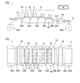
- FIG. 1A is a side view of a recording apparatus including a liquid ejection head according to an embodiment of the present disclosure
- FIG. 1B is a plan view.
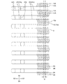
- (A) is a plan view of a head main body, which is a main part of the liquid ejection head of FIG. 1, and (b) is a plan view of (a) excluding a second flow path member.
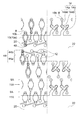
- FIG. 3 is an enlarged plan view of a part of FIG.
- FIG. 4 is an enlarged plan view of a part of FIG. 3.
- (A) is a schematic partial longitudinal sectional view of the head main body, and (b) is a longitudinal sectional view of another part of the head main body.
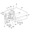
- FIG. 3 is a perspective view schematically illustrating a part of a flow path of a head body.
- FIG. 3 is a partially enlarged plan view of a first common channel and a bypass channel.
- FIG. 7 is a partially enlarged plan view of a second common channel and a bypass channel.
- FIG. 1A illustrates a color inkjet printer 1 (hereinafter, may be simply referred to as a printer) which is a recording apparatus including a liquid ejection head 2 (hereinafter, sometimes simply referred to as a head) according to an embodiment of the present disclosure.
- a printer which is a recording apparatus including a liquid ejection head 2 (hereinafter, sometimes simply referred to as a head) according to an embodiment of the present disclosure.
- FIG. 1 (b) is a schematic plan view.
- the printer 1 moves the printing paper P relative to the head 2 by transporting the printing paper P as a recording medium from the paper feeding roller 80A to the collection roller 80B.
- the paper feed roller 80A, the collection roller 80B, and various rollers described below constitute a moving unit 85 that relatively moves the print paper P and the head 2.
- the control unit 88 controls the head 2 based on print data or the like, which is data of images, characters, and the like, to discharge liquid toward the printing paper P, land droplets on the printing paper P, and perform printing.
- the recording such as printing is performed on the paper P.
- the head 2 is fixed to the printer 1, and the printer 1 is a so-called line printer.
- the printer 1 is a so-called line printer.
- a so-called serial printer which alternately conveys the printing paper P.
- Each frame 70 is provided with five holes (not shown), and five heads 2 are mounted on the respective holes.
- the five heads 2 mounted on one frame 70 constitute one head group 72.
- the printer 1 has four head groups 72, and a total of 20 heads 2 are mounted.
- the head 2 mounted on the frame 70 is configured such that a portion for discharging the liquid faces the printing paper P.
- the distance between the head 2 and the printing paper P is, for example, about 0.5 to 20 mm.
- the # 20 heads 2 may be directly connected to the control unit 88, or may be connected via a distribution unit that distributes print data therebetween.
- the control unit 88 may send print data to one distribution unit, and one distribution unit may distribute the print data to the 20 heads 2. Further, for example, the control unit 88 distributes print data to four distribution units corresponding to the four head groups 72, and each distribution unit distributes print data to the five heads 2 in the corresponding head group 72. Is also good.
- the head 2 has an elongated shape that is elongated in the direction from the near side to the back side in FIG. 1A and the up and down direction in FIG. 1B.
- the three heads 2 are arranged in a direction intersecting the transport direction of the printing paper P, for example, in a direction substantially orthogonal to the transport direction, and the other two heads 2 are arranged in the transport direction.
- one head is arranged between each of the three heads 2.
- the heads 2 are arranged in a staggered manner.
- the heads 2 are arranged such that the printable range of each head 2 is connected in the width direction of the printing paper P, that is, in the direction intersecting the transport direction of the printing paper P, or the ends are overlapped. Printing without gaps in the width direction of the printing paper P is enabled.
- the four head groups 72 are arranged along the transport direction of the printing paper P.
- Each head 2 is supplied with liquid, for example, ink from a liquid supply tank (not shown).
- the same color ink is supplied to the heads 2 belonging to one head group 72, and the four head groups 72 can print four color inks.
- the colors of the ink ejected from each head group 72 are, for example, magenta (M), yellow (Y), cyan (C), and black (K). If such an ink is controlled and printed by the control unit 88, a color image can be printed.
- the number of the heads 2 mounted on the printer 1 may be one as long as the printable area can be printed with one head 2 in a single color.
- the number of the heads 2 included in the head group 72 and the number of the head groups 72 can be appropriately changed according to a printing target and printing conditions.
- the number of head groups 72 may be increased to perform multi-color printing. If a plurality of head groups 72 for printing in the same color are arranged and printing is performed alternately in the transport direction, the transport speed can be increased even if the heads 2 having the same performance are used. Thereby, the printing area per time can be increased.
- a plurality of head groups 72 for printing in the same color may be prepared and displaced in a direction intersecting the transport direction to increase the resolution of the printing paper P in the width direction.
- a liquid such as a coating agent may be printed by the head 2 uniformly or by patterning in order to perform a surface treatment of the printing paper P.
- the coating agent for example, in the case where a recording medium is used that hardly penetrates the liquid, one that forms a liquid receiving layer so that the liquid can be easily fixed can be used.
- the liquid permeation suppression is performed so that the bleeding of the liquid does not become too large and the liquid does not mix too much with another liquid that has landed next to the recording medium. Those that form a layer can be used.
- the coating agent may be uniformly applied by the coating machine 76 controlled by the control unit 88 in addition to printing by the head 2.
- the printer 1 performs printing on the printing paper P as a recording medium.
- the printing paper P is wound around the paper feeding roller 80A, and the printing paper P sent out from the paper feeding roller 80A passes under the head 2 mounted on the frame 70, and then moves to the next position. After passing between the two transport rollers 82C, it is finally collected by the collection roller 80B. At the time of printing, the printing paper P is transported at a constant speed by rotating the transport roller 82C, and is printed by the head 2.
- the printing paper P sent from the paper feeding roller 80A passes between the two guide rollers 82A and then passes below the coating machine 76.
- the applicator 76 applies the above-described coating agent to the printing paper P.
- the printing paper P subsequently enters the head chamber 74 in which the frame 70 on which the head 2 is mounted is stored.
- the head chamber 74 is connected to the outside at a part such as a part where the printing paper P enters and exits, but is generally a space isolated from the outside.
- control factors such as temperature, humidity, and air pressure are controlled by the control unit 88 and the like as necessary.
- the influence of disturbance can be reduced as compared with the outside where the printer 1 is installed, so that the above-described fluctuation range of the control factor can be narrower than outside.
- Five guide rollers 82B are arranged in the head chamber 74, and the printing paper P is transported on the guide rollers 82B.
- the five guide rollers 82B are arranged so that the center becomes convex toward the direction in which the frame 70 is arranged when viewed from the side.
- the printing paper P conveyed over the five guide rollers 82B has an arc shape when viewed from the side, and by applying tension to the printing paper P, the printing paper P between the respective guide rollers 82B is formed.
- One frame 70 is arranged between the two guide rollers 82B. The angle at which each frame 70 is installed is slightly changed so as to be parallel to the printing paper P conveyed thereunder.
- the printing paper P that has exited from the head chamber 74 passes between the two transport rollers 82C, passes through the dryer 78, passes between the two guide rollers 82D, and is collected by the collection roller 80B.
- the transport speed of the printing paper P is, for example, 100 m / min.
- Each roller may be controlled by the control unit 88 or may be manually operated by a person.
- the dryer 78 may perform drying in order using a plurality of drying methods, or may use a plurality of drying methods in combination. Drying methods used in such a case include, for example, blowing of hot air, irradiation of infrared rays, and contact with a heated roller. When irradiating infrared rays, infrared rays in a specific frequency range may be applied so that drying can be performed faster while reducing damage to the printing paper P.
- the time during which heat is transmitted may be increased by transporting the printing paper P along the cylindrical surface of the roller.
- the range of conveyance along the cylindrical surface of the roller is preferably at least 4 of the cylindrical surface of the roller, and more preferably at least ⁇ of the cylindrical surface of the roller.
- a UV irradiation light source may be provided instead of or in addition to the dryer 78.
- a UV irradiation light source may be arranged between each frame 70.
- the printer 1 may include a cleaning unit for cleaning the head 2.
- the cleaning unit performs cleaning by, for example, wiping or capping.
- the wiping is performed, for example, by rubbing a surface of a portion to which the liquid is discharged, for example, a discharge hole surface 4-2 (described later) with a flexible wiper to remove the liquid attached to the surface.
- the cleaning by capping is performed, for example, as follows. First, a cap is placed so as to cover a portion from which liquid is discharged, for example, the discharge hole surface 4-2 (this is referred to as capping), so that the discharge hole surface 4-2 and the cap are substantially sealed and a space is formed. Made.
- the liquid, foreign matter, and the like, which are clogged in the discharge holes 8 (described later) and have higher viscosity than the standard state, are removed.
- the liquid being washed is less likely to scatter to the printer 1 and the liquid is less likely to adhere to the printing paper P or a transport mechanism such as a roller.
- the ejection hole surface 4-2 may be further wiped. The wiping and the cleaning by capping may be performed by manually operating a wiper or a cap attached to the printer 1 or automatically by the control unit 88.
- the recording medium may be a roll-shaped cloth or the like other than the printing paper P. Further, instead of directly transporting the printing paper P, the printer 1 may directly transport the transport belt and place the recording medium on the transport belt to transport. In this way, sheets, cut cloth, wood, tiles, etc. can be used as the recording medium. Furthermore, a wiring pattern or the like of an electronic device may be printed by discharging a liquid containing conductive particles from the head 2. Further, a chemical may be produced by discharging a predetermined amount of liquid chemical or a liquid containing the chemical from the head 2 toward a reaction container or the like to cause a reaction.
- a position sensor, a speed sensor, a temperature sensor, and the like may be attached to the printer 1, and the control unit 88 may control each unit of the printer 1 according to the state of each unit of the printer 1 that can be obtained from information from each sensor.
- the temperature of the head 2 the temperature of the liquid in the liquid supply tank that supplies the liquid to the head 2
- the pressure applied to the head 2 by the liquid in the liquid supply tank, and the like indicate the discharge characteristics of the liquid to be discharged
- the drive signal for discharging the liquid may be changed according to the information.
- FIG. 2A is a plan view showing a head main body 2a which is a main part of the head 2 shown in FIG.
- FIG. 2B is a plan view showing a state where the second flow path member 6 is removed from the head main body 2a.
- FIG. 3 is an enlarged plan view of the head main body 2a in the range of the alternate long and short dash line in FIG. 2B.
- FIG. 4 is an enlarged plan view of the head main body 2a in the range of the alternate long and short dash line in FIG.
- FIG. 5A is a schematic partial longitudinal sectional view of the head main body 2a.
- FIG. 5A in order to show a state where the flow paths are connected, flow paths that do not actually exist in the same vertical cross section are drawn as if they exist in the same vertical cross section.
- FIG. 5B also illustrates a signal transmission unit 60 not illustrated in FIG. 2A.
- FIG. 6 is a perspective view schematically showing a part of the flow path in the head main body 2a.
- FIGS. 2 to 4 the flow paths and the like which are to be drawn by broken lines below the others are drawn by solid lines.
- FIG. 4 the figure is divided into right and left parts by a two-dot chain line. On the left side of the two-dot chain line, a flow path from the first common flow path 20 to the discharge hole 8 is drawn. On the right side of the two-dot chain line, a flow path from the discharge hole 8 to the second common flow path 22 is drawn.
- individual electrodes 44 and connection electrodes 46 are also illustrated.
- the head 2 may include a housing, a driver IC, a wiring board, and the like, in addition to the head main body 2a.
- the head main body 2a includes a first flow path member 4, a second flow path member 6 for supplying a liquid to the first flow path member 4, and a piezoelectric actuator in which a displacement element 50 serving as a pressurizing unit is formed. And a substrate 40.
- the head main body 2a has a flat plate shape that is long in one direction, and that direction may be referred to as a longitudinal direction.
- the second flow path member 6 serves as a support member for supporting the structure of the head main body 2a.
- the head main body 2a is fixed to the frame 70 at each of both longitudinal ends of the second flow path member 6. Is done.
- the first flow path member 4 constituting the head main body 2a has a flat plate shape, and has a thickness of about 0.5 to 2 mm.
- a plurality of pressurizing chambers 10 are arranged in a plane on a pressurizing chamber surface 4-1 which is one surface of the first flow path member 4.
- a large number of discharge holes 8 for discharging liquid are arranged in a plane direction on a discharge hole surface 4-2 of the first flow path member 4 opposite to the pressurizing chamber surface 4-1. .
- the discharge holes 8 are connected to the pressurizing chambers 10, respectively.
- the description will be made on the assumption that the pressure chamber surface 4-1 is located above the discharge hole surface 4-2.
- a plurality of first common flow paths 20 and a plurality of second common flow paths 22 are arranged in the first flow path member 4 so as to extend along the first direction.
- the first common channel 20 and the second common channel 22 may be collectively referred to as a common channel.
- At least a part of the first common flow path 20 and the second common flow path 22 are arranged so as to overlap with each other. For example, 80% or more of the widths overlap each other, or the entire widths overlap each other.
- the direction that intersects the first direction is referred to as a second direction.
- the first direction is the same direction as the longitudinal direction of the head main body 2a.
- a direction opposite to the first direction is defined as a third direction
- a direction opposite to the second direction is defined as a fourth direction.
- the first to fourth directions are indicated by D1 to D4.
- the pressurized chamber 10 is connected to the first common flow path 20 and the second common flow path 22, and is connected to the pressurized chamber 10.
- the discharge holes 8 are arranged.
- the pressurizing chambers 10 connected to the first common flow path 20 and the second common flow path 22 constitute four pressurizing chamber rows 11A, each having two rows on one side of the common flow path and two rows on both sides. I have.
- the discharge holes 8 connected to the first common flow path 20 and the second common flow path 22 constitute four discharge hole rows 9A each having two rows on one side of the common flow path and a total of two rows on both sides. I have. Since there are eight first common channels 20 and second common channels 22, there are 32 rows of pressurizing chambers 11A in total and 32 rows of discharge hole rows 9A in total.
- the first common flow path 20 and the four rows of pressurizing chambers 10 arranged on both sides thereof are connected via the first relay flow path 12.
- the second common flow channel 22 and the four rows of pressurizing chambers 10 arranged on both sides thereof are connected via the second relay flow channel 14.
- the liquid supplied to the first common flow path 20 flows into the pressurizing chambers 10 arranged along the first common flow path 20.
- a part of the liquid that has flowed into the pressurizing chamber 10 is discharged from the discharge hole 8, and another part flows into the second common flow path 22 that is arranged to overlap the first common flow path 20, and It is discharged from the flow path member 4 to the outside.
- the first common channel 20 is a channel through which the liquid supplied to the pressurizing chamber 10 flows, and can be referred to as a supply channel.
- the second common flow path 22 is a flow path through which the liquid collected from the pressurized chamber 10 flows, and can be referred to as a recovery flow path. Note that the flow of liquid supply and recovery may be reversed, including the following description.
- the first common flow path 20 is disposed so as to overlap the second common flow path 22.
- the first common flow path 20 has an opening 20b disposed at both ends in the first direction and the third direction outside the range where the first relay flow path 12 is connected. Open to the outside.
- the second common flow path 22 has both ends in the first direction and the third direction outside the range where the second relay flow path 14 is connected and outside the opening 20 b of the first common flow path 20.
- the opening 22b is disposed outside the first flow path member 4. Since the opening 22b of the second common flow path 22 disposed on the lower side is disposed outside the opening 20b of the first common flow path 20 disposed on the upper side, space efficiency is improved.
- the entirety of the second common flow path main body 22a excluding both ends is disposed below the entirety of the first common flow path main body 20a excluding both ends.
- a substantially equal amount of liquid is supplied from the opening 20b on the first direction side and the opening 20b on the third direction side of the first common flow path 20, and flows toward the center of the first common flow path 20.
- the discharge amount of the liquid from the discharge holes 8 connected to one first common flow path 20 and one second common flow path 22 is substantially constant regardless of the location, the flow of the first common flow path 20 , Slows down toward the center, and becomes 0 (zero) almost at the center.
- the flow in the second common flow channel 22 is opposite to this, and is 0 (zero) substantially at the center, and the flow becomes faster toward the outside.
- the discharge amount of the liquid from the discharge holes 8 connected to one first common flow path 20 and one second common flow path 22 has various distributions.
- the location where the flow becomes 0 (zero) is on the first direction side from the center.
- the discharge amount from the discharge hole 8 in the third direction is large, the place where the flow becomes 0 (zero) is on the third direction side from the center.
- the location where the flow becomes 0 (zero) moves due to the change in the distribution of ejection depending on what is recorded.
- the pressure applied to the portion of the first relay flow path 12 connected to the first common flow path 20 on the first common flow path 20 side is affected by the pressure loss and the first relay flow path 12 Varies depending on the position where is connected (mainly the position in the first direction).
- the pressure applied to the portion on the side of the second relay flow path 14 connected to the second common flow path 22 is affected by the pressure loss, and the position where the second relay flow path 14 is connected to the second common flow path 22 (main Position in the first direction). If the pressure of the liquid in one discharge hole 8 is set to approximately 0 (zero), the above-mentioned pressure change changes symmetrically, so that the pressure of the liquid in all the discharge holes 8 can be set to approximately 0 (zero).
- the lower surface of the first common flow path 20 is a damper 28A.
- the surface of the damper 28A opposite to the surface facing the first common flow path 20 faces the damper chamber 29A.
- the damper chamber 29 ⁇ / b> A contains gas such as air, and its volume changes according to the pressure applied from the first common channel 20.
- the damper 28A can vibrate by changing the volume of the damper chamber 29A, and the vibration can be attenuated to attenuate the pressure fluctuation generated in the first common flow path 20.
- pressure fluctuation such as resonance of the liquid in the first common flow path 20 can be reduced.
- the lower surface of the second common flow path 22 is a damper 28B.
- the surface of the damper 28B opposite to the surface facing the second common flow path 22 faces the damper chamber 29B.
- the discharge holes 8 are arranged at an interval of 50 dpi (about 25.4 mm / 50).
- the second flow path member 6 is joined to the pressurizing chamber surface 4-1 of the first flow path member 4, and is connected to the first integrated flow path 24 for supplying liquid to the first common flow path 20 and the second common flow path 24.
- the thickness of the second flow path member 6 is larger than that of the first flow path member 4, and is about 5 to 30 mm.
- the second flow path member 6 is joined in a region of the pressurizing chamber surface 4-1 of the first flow path member 4 where the piezoelectric actuator substrate 40 is not connected. More specifically, they are joined so as to surround the piezoelectric actuator substrate 40. By doing so, it is possible to prevent a part of the discharged liquid from adhering to the piezoelectric actuator substrate 40 as a mist. Further, since the first flow path member 4 is fixed at the outer periphery so as to surround the piezoelectric actuator substrate 40, the first flow path member 4 vibrates in accordance with the driving of the displacement element 50, thereby reducing the resonance that occurs. it can.
- an opening 24b that is open on the upper surface of the second flow path member 6 is disposed.
- the first integrated flow path 24 is branched into two in the middle, one is connected to the opening 20b of the first common flow path 20 on the third direction side, and the other is the first common flow path on the first direction side. 20 are connected to the opening 20b.
- an opening 26b that is open on the upper surface of the second flow path member 6 is arranged.
- the second integrated flow path 26 is branched into two on the way, one of which is connected to the opening 22b of the second common flow path 22 in the first direction, and the other is the second common flow path in the third direction. 22 is connected to the opening 22b.
- the second flow path member 6 is provided with a through-hole 6 a vertically penetrating the second flow path member 6.
- a signal transmission unit 60 such as an FPC (Flexible Printed Circuit) that transmits a drive signal for driving the piezoelectric actuator substrate 40 is passed through the through hole 6a.
- the cross-sectional area of the first integrated channel 24 is increased. Accordingly, a difference in pressure loss due to a difference in a position where the first integrated flow path 24 and the first common flow path 20 are connected can be reduced.
- the flow resistance of the first integrated flow path 24 is preferably set to 1/100 or less of the first common flow path 20.
- the flow path resistance of the first integrated flow path 24 is, more precisely, a flow path resistance in a range connected to the first common flow path 20 in the first integrated flow path 24.
- the cross-sectional area of the second integrated channel 26 is increased. Accordingly, the difference in pressure loss due to the difference in the position where the second integrated flow path 26 and the second common flow path 22 are connected can be reduced.
- the flow resistance of the second integrated flow path 26 is preferably set to 1/100 or less of the second common flow path 22.
- the flow path resistance of the second integrated flow path 26 is, more precisely, a flow path resistance in a range connected to the first integrated flow path 24 in the second integrated flow path 26.
- the first integrated flow path 24 is disposed at one end of the second flow path member 6 in the short direction
- the second integrated flow path 26 is disposed at the other end of the second flow path member 6 in the short direction
- Each of the flow paths is directed toward the first flow path member 4 and is connected to the first common flow path 20 and the second common flow path 22, respectively.
- the cross-sectional area of the first integrated channel 24 and the second integrated channel 26 can be increased, and the channel resistance can be reduced.
- the outer periphery of the first flow path member 4 is fixed by the second flow path member 6, so that the rigidity can be increased.
- the through hole 6a through which the signal transmission unit 60 passes can be provided.
- a groove serving as the first integrated flow path 24 (first integrated flow path main body 24a) and a groove serving as the second integrated flow path 26 (second integrated flow path main body 26a) are provided on the lower surface of the second flow path member 6.
- Part of the lower surface of the groove serving as the first integrated channel main body 24 a is closed by the upper surface of the first channel member 4.
- the other part of the lower surface is connected to the opening 20b of the first common flow path 20.
- a part of the lower surface of the groove serving as the second integrated channel main body 26 a is closed by the upper surface of the first channel member 4.
- the other portion of the lower surface is connected to the opening 22b of the second common flow channel 22.
- a damper may be provided in the first integrated flow path 24 and the second integrated flow path 26 so that the supply or discharge of the liquid is stabilized with respect to the fluctuation of the discharge amount of the liquid. Further, by providing a filter inside the first integrated channel 24 and the second integrated channel 26 and between the first common channel 20 and the second common channel 22, foreign matter and air bubbles can be reduced to the first common channel 20 or the second common channel 22. It may be difficult to enter the flow path member 4.
- the upper surface of the second flow path member 6 is closed by a metal casing or the like.
- the signal transmission unit 60 is electrically connected to, for example, a wiring board housed in a housing.
- the wiring board and the control unit 88 are electrically connected by a cable or the like.
- a driver IC for driving the displacement element 50 may be mounted on the signal transmission unit 60. By bringing the driver IC into contact with a metal housing or a member that allows heat to be easily transmitted to the housing, heat generated by the driver IC can be released to the outside.
- the piezoelectric actuator substrate 40 including the displacement elements 50 is joined to the pressure chamber surface 4-1 which is the upper surface of the first flow path member 4, so that each displacement element 50 is positioned on the pressure chamber 10. Are located.
- the piezoelectric actuator substrate 40 occupies a region having substantially the same shape as the pressure chamber group constituted by the pressure chambers 10.
- the opening of each pressurizing chamber 10 is closed by joining the piezoelectric actuator substrate 40 to the pressurizing chamber surface 4-1 of the first flow path member 4.
- the piezoelectric actuator substrate 40 has a rectangular shape that is long in the same direction as the head main body 2a.
- the signal transmission unit 60 that supplies a signal to each displacement element 50 is connected to the piezoelectric actuator substrate 40.
- the second flow path member 6 has a through hole 6a vertically penetrating at the center, and the signal transmission unit 60 is electrically connected to the control unit 88 through the through hole 6a.
- the signal transmission unit 60 has a shape that extends in the short direction from the end of one long side of the piezoelectric actuator substrate 40 to the end of the other long side, and the wiring arranged in the signal transmission unit 60 extends in the short direction. If they extend along the length and are arranged in the longitudinal direction, the distance between the wirings can be increased.
- the first flow path member 4 has a laminated structure in which a plurality of plates are laminated.
- a plate 4a is arranged on the side of the pressure chamber surface 4-1 of the first flow path member 4, and plates 4b to 4o are sequentially stacked below the plate 4a.
- the plate 4a in which the hole serving as the side wall of the pressurizing chamber 10 is formed is called a cavity plate 4a, and the plates 4f, 4g, 4h, 4i, 4l, and 4m in which the hole serving as the side wall of the common flow path is formed.
- manifold plates 4f, 4g, 4h, 4i, 4l, and 4m are referred to as manifold plates 4f, 4g, 4h, 4i, 4l, and 4m
- the plate 4o in which the discharge holes 8 are opened may be referred to as a nozzle plate 4o.
- Each plate has a large number of holes and grooves.
- the holes and grooves can be formed by, for example, forming each plate with metal and etching. When the thickness of each plate is about 10 to 300 ⁇ m, the accuracy of forming holes can be increased.
- the plates are aligned and laminated so that these holes communicate with each other to form a flow path such as the first common flow path 20.
- the pressurizing chamber main body 10a is opened in the pressurizing chamber surface 4-1 of the first flat channel member 4, and the piezoelectric actuator substrate 40 is joined thereto.
- an opening 20b for supplying liquid to the first common flow path 20 and an opening 22b for collecting liquid from the second common flow path 22 are opened in the pressurizing chamber surface 4-1.
- a discharge hole 8 is opened on a discharge hole surface 4-2 of the first flow path member 4 opposite to the pressurizing chamber surface 4-1.
- the pressurizing chamber 10 includes a pressurizing chamber main body 10a facing the displacement element 50, and a partial flow path 10b connecting the pressurizing chamber main body 10a and the discharge hole.
- the pressurizing chamber main body 10a is formed in the cavity plate 4a, and the partial flow path 10b is formed by overlapping holes formed in the plates 4b to 4n, and further closed by the nozzle plate 4o (the portion other than the discharge holes 8). It's made up.
- the first relay channel 12 is connected to the pressurizing chamber main body 10a, and the first relay channel 12 is connected to the first common channel 20.
- the first relay channel 12 includes a circular hole penetrating the plate 4b, an elongated penetrating groove extending in the plane direction of the plate 4c, and a circular hole penetrating the plates 4d and 4e.
- the second relay flow path 14 is connected to the partial flow path 10b, and the second relay flow path 14 is connected to the second common flow path 22.
- the second relay flow path 14 includes an individual flow path 14a connected to one pressurization chamber 10 and a connection flow path 14b connected to another pressurization chamber 10.
- the two individual flow paths 14a respectively connected to the two pressurizing chambers 10 are combined into one connection flow path 14b, and then connected to the second common flow path 22.
- the number of connection flow paths 14b connected to one second common flow path 22 is plural.
- the number of the connection channels 14 b connected to one second common channel 22 is half the number of the pressurizing chambers 10 connected to one second common channel 22.
- the space efficiency is improved by connecting the plurality of individual flow paths 14a to the second common flow path 22 after being bundled in the connection flow path 14b.
- the number of the individual flow paths 14a connected to the connection flow path 14b may be three or more.
- two second relay channels 14 may be provided for the two pressurizing chambers 10 and may be regarded as sharing one connecting channel 14b, And one second relay flow path 14 may be regarded as having two individual flow paths 14a.
- the former method is mainly used. Is expressed.
- the first common flow path 20 has holes formed in the plates 4f to 4i overlapped, and the upper side is closed by a plate 4e and the lower side is closed by a plate 4j.
- the second common flow path 22 has holes formed in the plates 41 and 4m overlapped, and the upper side is closed by a plate 4k and the lower side is closed by a plate 4n.
- the liquid supplied to the first integrated flow path 24 enters the pressurizing chamber 10 through the first common flow path 20 and the first relay flow path 12 in order, and a part of the liquid is discharged. Discharged from the hole 8.
- the liquid that has not been discharged passes through the second relay flow path 14, enters the second common flow path 22, enters the second integrated flow path 26, and is discharged to the outside of the head main body 2a.
- the piezoelectric actuator substrate 40 has a laminated structure including two piezoelectric ceramic layers 40a and 40b that are piezoelectric bodies. Each of these piezoelectric ceramic layers 40a and 40b has a thickness of about 20 ⁇ m. That is, the thickness from the upper surface of the piezoelectric ceramic layer 40a to the lower surface of the piezoelectric ceramic layer 40b of the piezoelectric actuator substrate 40 is about 40 ⁇ m.
- the thickness ratio of the piezoelectric ceramic layer 40a to the piezoelectric ceramic layer 40b is set to 3: 7 to 7: 3, preferably 4: 6 to 6: 4.
- Each of the piezoelectric ceramic layers 40a and 40b extends so as to straddle the plurality of pressure chambers 10.
- the piezoelectric ceramic layers 40a and 40b for example, strength with a dielectric, lead zirconate titanate (PZT), NaNbO 3 system, BaTiO 3 system, (BiNa) NbO 3 system, such as BiNaNb 5 O 15 system Made of ceramic material.
- PZT lead zirconate titanate
- NaNbO 3 system NaNbO 3 system
- BaTiO 3 system BaTiO 3 system
- BiNa NbO 3 system such as BiNaNb 5 O 15 system Made of ceramic material.
- the piezoelectric ceramic layer 40b functions as a diaphragm, and does not directly undergo piezoelectric deformation.
- a ceramic or metal plate having no piezoelectricity may be used instead of the piezoelectric ceramic layer 40b.
- the piezoelectric actuator substrate 40 has a common electrode 42 made of a metal material such as Ag-Pd and an individual electrode 44 made of a metal material such as Au.
- the thickness of the common electrode 42 is about 2 ⁇ m, and the thickness of the individual electrode 44 is about 1 ⁇ m.
- the individual electrodes 44 are arranged at positions on the upper surface of the piezoelectric actuator substrate 40 that face the respective pressure chambers 10.
- the individual electrode 44 has a planar shape slightly smaller than the main body 10a of the pressurizing chamber, and has an approximately similar shape to the main body 10a of the pressurizing chamber, and an extraction electrode drawn from the main body 44a of the individual electrode. 44b.
- a connection electrode 46 is formed at a portion of one end of the extraction electrode 44b that is extracted outside a region facing the pressurizing chamber 10.
- the connection electrode 46 is, for example, a conductive resin containing conductive particles such as silver particles, and is formed with a thickness of about 5 to 200 ⁇ m.
- the connection electrode 46 is electrically connected to an electrode provided on the signal transmission unit 60.
- a drive signal is supplied to the individual electrode 44 from the control unit 88 through the signal transmission unit 60.
- the drive signal is supplied at a constant period in synchronization with the transport speed of the printing paper P.
- the common electrode 42 is formed in a region between the piezoelectric ceramic layer 40a and the piezoelectric ceramic layer 40b over substantially the entire surface in the surface direction. That is, the common electrode 42 extends so as to cover all the pressurizing chambers 10 in the region facing the piezoelectric actuator substrate 40.
- the common electrode 42 is formed on a surface electrode for common electrode (not shown) formed at a position avoiding the electrode group including the individual electrodes 44 on the piezoelectric ceramic layer 40a, and a through conductor formed through the piezoelectric ceramic layer 40a. Are connected via. Further, the common electrode 42 is grounded via a common electrode surface voltage, and is held at the ground potential.
- the common electrode surface electrode is directly or indirectly connected to the control unit 88 in the same manner as the individual electrode 44.
- the portion of the piezoelectric ceramic layer 40a sandwiched between the individual electrode 44 and the common electrode 42 is polarized in the thickness direction, and becomes a unimorph displacement element 50 that is displaced when a voltage is applied to the individual electrode 44. I have. More specifically, when an electric field is applied to the piezoelectric ceramic layer 40a in the direction of its polarization by setting the individual electrode 44 to a potential different from that of the common electrode 42, the portion to which the electric field is applied is distorted by the piezoelectric effect.
- the displacement element 50 is driven (displaced) by a drive signal supplied to the individual electrode 44 via a driver IC or the like under the control of the control unit 88.
- the liquid can be ejected by various drive signals.
- a so-called pull driving method will be described.
- the individual electrode 44 is previously set at a higher potential than the common electrode 42 (hereinafter, referred to as a high potential), and the individual electrode 44 is once set to the same potential as the common electrode 42 (hereinafter, referred to as a low potential) every time there is a discharge request. Thereafter, at a predetermined timing, the potential is increased again.
- the piezoelectric ceramic layers 40a and 40b return (start) to the original (flat) shape, and the volume of the pressurizing chamber 10 is initialized (the potential of both electrodes is different). State). Thereby, a negative pressure is applied to the liquid in the pressurizing chamber 10. Then, the liquid in the pressurized chamber 10 starts to vibrate at the natural vibration cycle.
- the volume of the pressurizing chamber 10 starts to increase, and the negative pressure gradually decreases.
- the volume of the pressurizing chamber 10 becomes maximum and the pressure becomes almost zero.
- the volume of the pressurizing chamber 10 starts to decrease, and the pressure increases.
- the individual electrode 44 is set to a high potential.
- the first applied vibration and the second applied vibration overlap, and a greater pressure is applied to the liquid. This pressure propagates in the partial flow path 10b and causes the liquid to be discharged from the discharge hole 8.
- a droplet can be discharged by supplying a drive signal of a pulse that keeps a low potential for a certain period with respect to the high potential to the individual electrode 44.
- this pulse width is set to AL (Acoustic Length), which is half the period of the natural oscillation period of the liquid in the pressurizing chamber 10, the discharge speed and the discharge amount of the liquid can be maximized in principle.
- AL Acoustic Length
- the natural oscillation period of the liquid in the pressurizing chamber 10 is greatly influenced by the physical properties of the liquid and the shape of the pressurizing chamber 10.
- the physical properties of the piezoelectric actuator substrate 40 and the flow path connected to the pressurizing chamber 10 are different. Is also affected by the characteristics of
- the first common channel 20 has a larger cross-sectional area to supply the liquid to be discharged.
- the cross-sectional area of the second common flow channel 22 should also be somewhat large.
- the width of the head body 2a in the short direction increases, and the range in which the ejection holes 8 are distributed in the short direction also increases. If the distribution range of the ejection holes 8 in the short direction is widened, the printing accuracy is greatly reduced when the installation angle of the head 2 is shifted so as to rotate in the plane direction, which is not desirable.
- the arrangement interval of the common flow channel may be reduced. If the space efficiency of the channels arranged between the common channels is improved, the arrangement interval of the common channels can be reduced. Since the second relay flow path 14 is a flow path connected to the vicinity of the discharge hole 8 of the pressurizing chamber 10, if the space efficiency of the arrangement of the second relay flow path 14 is improved, the arrangement interval of the common flow path is reduced. it can.
- the cross-sectional area and the length of the second relay channel 14 are preferably substantially the same in design. Further, it is desirable that the second relay channel 14 has channel characteristics suitable for discharge, and has a cross-sectional area and a length suitable for achieving the channel characteristics. Simply for improving the space efficiency, for example, a flow path that connects the shortest distance with a straight line may be provided, but it is difficult for such a flow path to have the flow path characteristics as described above. is there.
- the second common flow path Connect to 22 More specifically, after the individual flow paths 14a connected to only one pressurizing chamber 10 are bundled as the connection flow paths 14b, the individual flow paths 14a are connected to the second common flow path 22. In other words, a plurality of individual flow paths 14a are connected to one connection flow path 14b. That is, a plurality of individual flow paths 14a are connected to the upstream end of the connection flow path 14b constituting the second relay flow path 14, and the second common flow path 22 is connected to the downstream end of the connection flow path 14b. Connected configuration. Thereby, the space required for disposing the flow paths can be reduced as compared with the case where completely individual flow paths are provided.
- the pressurizing chamber 10 And the second common flow path 22 are completely connected by a separate second relay flow path, and the second relay flow path is assumed to have the shortest distance.
- the second relay flow path connected to the pressurized chamber 10 far from the second common flow path 22 is the second relay flow path connected to the pressurized chamber 10 closer to the second common flow path 22. It is longer than the flow path. As a result, the two flow path characteristics are different.
- the second common flow path 22 While making the second relay channel 14 connected to the close pressurizing chamber 10 longer, the longer channel can be efficiently arranged.
- connection flow path 14b is longer than the individual flow path 14a, that is, the higher the proportion of the connection flow path 14b in the second relay flow path 14, the higher the space efficiency.
- a part of the pressure at which the liquid is discharged from the plurality of pressurizing chambers 10 is transmitted to the liquid in the second common flow path 22, causing complicated pressure vibration.
- a part of the pressure vibration is transmitted to the pressurizing chamber 10 and may affect the subsequent discharge. If the pressures from the two pressurizing chambers 10 are combined in the connection channel 14b before being transmitted to the second common channel 22, the complexity of the pressure oscillation in the second common channel 22 can be reduced. The effect on subsequent ejection can be reduced. If the Newtonian fluid is filled in the complete columnar flow path, the pressure waves are transmitted independently, but if the flow path is an actual flow path and a real liquid, the pressures affect each other.
- the connection flow path 14b is preferably longer than the individual flow path 14a so that the synthesis of pressure proceeds.
- the discharge pressure generated in one pressurizing chamber 10 passes through an individual flow path 14a connected to the pressurizing chamber 10 and then passes through an individual flow path 14a connected to another pressurizing chamber 10, and To the pressure chamber 10.
- the flow resistance of the individual flow path 14a is larger than the flow resistance of the connection flow path 14b.
- connection flow path 14b After bundling a plurality of individual flow paths 14a to form a connection flow path 14b, by connecting to the second common flow path 22, space efficiency can be improved.
- the second relay flow path 14 connected to the discharge hole 8 arranged in the first gap region can be accommodated and arranged in the first gap region.
- connection flow path 14b After bundling a plurality of individual flow paths 14a to form a connection flow path 14b, by connecting to the second common flow path 22, space efficiency can be improved.
- the second relay flow path 14 connected to the discharge hole 8 arranged in the second gap area can be accommodated and arranged in the second gap area.
- the second relay flow path 14 is connected near the discharge hole 8 of the partial flow path 10b so that the liquid near the discharge hole 8 does not stay.
- the second relay flow path 14 is disposed closer to the discharge hole surface 4-2 than the first common flow path 20 is.
- a plurality of individual flow paths 14a are bundled to form a connection flow path 14b, and then connected to the second common flow path 22, so that space efficiency can be improved, and the second common flow path 22 and the second relay
- the flow path 14 can be arranged closer to the discharge hole surface 4-2 than the first common flow path 20 is.
- the entirety of the second common flow path 22 except for both ends and the entirety of the second relay flow path 14 can be arranged closer to the discharge hole surface 4-2 than the first common flow path 20 is.
- the individual channel 14a includes a first portion 14aa directly connected to the pressurizing chamber 10, and a second portion 14ab connecting the first portion 14aa and the connection channel 14b.
- the first portion 14aa is configured by closing a hole or a groove arranged on one plate 4n with a plane portion of the other plates 4m and 4o.
- the second portion 14ab is formed such that holes or grooves arranged in a plate 4m different from the plate 4n in which holes or grooves constituting the first portion 14aa are arranged are formed by plane portions of the other plates 4l and 4n. It is made up of blockages.
- the flow path resistance per unit length of the first part 14aa is larger than the flow path resistance per unit length of the second part 14ab. This makes it difficult for the pressure from the pressurizing chamber 10 to be transmitted to the second relay channel 14 and makes it difficult for the pressure oscillation in the pressurizing chamber 10 to be complicated.
- the first portion 14aa is directly connected to the pressurizing chamber 10, the reflection of the pressure wave mainly occurs at the connection portion. As a result, the pressure oscillation in the pressurizing chamber 10 becomes relatively simple, and it becomes relatively easy to perform the next ejection in accordance with the pressure oscillation.
- the plate 4m is thicker than the plate 4n.
- the first portion 14aa can satisfy necessary flow path characteristics (flow path resistance and the like).
- the individual flow paths 14a can be connected to each other by the second part 14ab having a larger cross-sectional area than the first part 14aa and having a small influence of the flow path characteristics on the individual flow paths 14a.
- the plate 4m is a plate on which holes or grooves are arranged to be the second common flow path 22, the number of required plates can be reduced. Further, by making the plate 4n thinner than the plate 4m, the AL of the pressurizing chamber 10 can be shortened, and the head 2 can be driven in a short cycle.
- the angle formed by the individual flow paths 14a is smaller than the angle formed by the individual flow path 14a and the connection flow path 14b. .
- the angle formed by the individual channels 14a is about 80 degrees.
- the angle formed between the individual flow path 14a and the connection flow path 14b is substantially 90 degrees because the connection flow path 14b is connected to the individual flow path 14a so as to rise upward. Therefore, the magnitude relationship between those angles is as described above.
- the pressure transmitted from one individual flow path 14a is more easily transmitted to the connection flow path 14b than to the other individual flow path 14a.
- the pressure propagation generated between the pressurized chambers 10 connected via each other can be reduced.
- the above-described condition is satisfied in both of the two individual flow paths 14a. However, even if only one individual flow path 14a is satisfied, the above-described effect is obtained for the individual flow path 14a. is there. If all the individual flow paths 14a are satisfied, the above-described effects are obtained for all the individual flow paths 14a.
- the first flow path member 4 has a bypass flow path 16 connecting the first common flow path 20 and the second common flow path 22.
- the pressurizing chamber 10 also connects the first common channel 20 and the second common channel 22.
- the bypass flow path 16 is connected to the first common flow path 20 and the second common flow path 22 so as to be parallel to the pressurizing chamber 10.
- the parallel is a parallel connection (parallel of series connection and parallel connection), and a parallel spatial relationship (extends in parallel in the same direction). State) is not.
- the bypass referred to here does not necessarily mean a detour (detour), but includes a shortcut. That is, the path from the first common flow path 20 to the second common flow path 22 via the bypass flow path 16 is connected to the second common flow path 22 from the first common flow path 20 via the pressurizing chamber 10. It may be shorter than the path leading to.
- the bypass flow path 16 has one end connected to the first common flow path 20 and the other end connected to the second relay flow path 14. That is, the other end of the bypass flow path 16 is connected to the second common flow path 22 via the connection flow path 14b.
- the bypass flow path 16 can be regarded as sharing the connection flow path 14b with the second relay flow path 14 (the bypass flow path 16 includes the connection flow path 14b). In the description of the embodiment, the bypass flow path 16 is expressed as not including the connection flow path 14b.
- the unit flow path 18 includes one first common flow path 20 and one second common flow path 22, a plurality of first relay flow paths 12 connecting the two, and a plurality of pressurizing chambers. 10, a plurality of second relay flow paths 14 and a plurality of bypass flow paths 16, and a plurality of discharge holes 8 connected to the plurality of pressurizing chambers 10 included in the unit flow path 18.
- FIGS. 7 and 8 are plan views for explaining the connection position of the bypass flow path 16 in the flow direction of the common flow path.
- FIG. 7 shows a first common channel 20, a plurality of first relay channels 12, and a plurality of bypass channels 16 for one unit channel 18.
- FIG. 8 shows a second common flow path 22, a plurality of second relay flow paths 14 (more specifically, connection flow paths 14b), and a plurality of bypass flow paths 16 for one unit flow path 18.
- one unit channel 18 will be described, but the same may be applied to other unit channels 18.
- the first common flow path 20 is connected to (directly) the first connection flow paths 12 by the first connection area. 20e, and a first non-connection area 20f that is not (directly) connected to the plurality of first relay channels 12.
- the second common flow path 22 is connected (directly) to the plurality of second relay flow paths 14. It has two connection regions 22e and a second non-connection region 22f that is not (directly) connected to the plurality of second relay channels 14.
- bypass flow path 16 includes a first connection area 20e and a second connection area 22e (strictly, a connection flow path 14b connected to the second connection area 22e. , And so on.).
- the plurality of bypass channels 16 may include the bypass channel 16 connected to the first non-connection region 20f and / or the second non-connection region 22f.
- first connection region 20e and the second connection region 22e may be appropriately defined. For example, specifically, it is as follows.
- the first connection region 20e and the first non-connection region 20f pass through the first common flow path 20 in the flow direction (in other words, the longitudinal direction or the direction in which the ink flows; the second common flow path). 22 and the like.)).
- the second connection region 22e and the second non-connection region 22f are regions that divide the second common flow channel 22 in the flow direction.
- the first common flow path 20 has a plurality of first openings 20h individually connected to the plurality of first relay flow paths 12.
- the plurality of first openings 20h are distributed in the flow direction of the first common flow path 20. More specifically, the plurality of first openings 20h are arranged in the flow path direction in one or more rows (four rows in the illustrated example). In such a configuration, the first opening 20h located on the most one side (left side in the drawing) in the flow path direction is defined as a first opening 20h-A. Further, the first opening 20h located on the other side (right side in the drawing) in the flow path direction is defined as a first opening 20h-B.
- the portion from the position of the first opening 20h-A to the position of the first opening 20h-B may be the first connection region 20e.
- the position of the first opening 20h-A may be, for example, based on the edge of the first opening 20h-A on the one side (left side in the drawing).
- the position of the first opening 20h-B may be based on, for example, the edge of the first opening 20h-B on the other side (right side in the drawing).
- the second common flow path 22 has a plurality of second openings 22h individually connected to the plurality of second relay flow paths 14.
- the plurality of second openings 22 h are distributed in the flow direction of the second common flow path 22. More specifically, the plurality of second openings 22h are arranged in the flow direction in one or more rows (two rows in the illustrated example).
- the second opening 22h located at the most one side (left side in the drawing) in the flow path direction is defined as a second opening 22h-A.
- the second opening 22h located on the other side (the right side in the drawing) in the flow path direction is defined as a second opening 22h-B.
- the area from the position of the second opening 22h-A to the position of the second opening 22h-B may be used as the second connection region 22e.
- the position of the second opening 22h-A may be based on, for example, the edge of the second opening 22h-A on the one side (left side in the drawing).
- the position of the second opening 22h-B may be based on, for example, the edge of the second opening 22h-B on the other side (right side in the drawing).
- first non-connection region 20f the outside of both sides of the first openings 20h-A and 20h-B may be regarded as the first non-connection region 20f.
- outer sides on both sides of the second openings 22h-A and 22h-B may be regarded as the second non-connection regions 22f.
- the first openings 20h-A and / or the first openings 20h-B are located at the ends of the first common flow path 20, so that both sides of the first connection region 20e and / or It is also possible not to provide the first non-connection region 20f on one side.
- the first connection region 20e may be a part of the first common flow channel 20 as in the embodiment, or may be the entire first common flow channel unlike the embodiment. Good.
- the length (the flow direction) of the first non-connection region 20f is determined by the distance between the adjacent first openings 20h in each row as in the embodiment ( Alternatively, it may be longer than the pitch Pt), and unlike the embodiment, may be shorter than the distance between the adjacent first openings 20h in each row.
- the first non-connection region 20f has been described, the same applies to the second non-connection region 22f.
- the first common flow path 20 has a configuration having both ends. Therefore, as described above, the first openings 20h-A and 20h-B are located at both ends in the flow direction of the first common flow path 20 among the plurality of first openings 20h. May be. However, although not particularly shown, the first common flow path may be annular. Also in this case, the position of the opening corresponding to the opening 20b for supplying the ink to the first common flow path 20 is regarded as the end of the first common flow path, so that the first opening closest to the end may be specified. . Similarly, regarding the second common flow path 22, the position of the opening corresponding to the opening 22b may be regarded as the end of the second common flow path, and the second opening closest to the end may be specified.
- the first non-connection region may be provided at a position apart from the opening corresponding to the opening 20b.
- a first non-connection region may be provided in the folded portion and its periphery.
- the specification of the first opening (20h-A / 20h-B) defining the end of the first connection region and the determination of the presence or absence of the first non-connection region may be rationally performed.
- the first connection region is usually a straight line parallel to the pressurizing chamber row (discharge hole row). Therefore, the first opening closest to the folded portion may be regarded as the first opening located at the end of the first connection region. That is, even if there is a conventional technique in which a return flow path is provided with a bypass flow path that connects the first common flow path and the second common flow path, the bypass flow path is the bypass flow path of the present embodiment. It does not correspond to the road 16.
- the plurality of first openings are basically arranged at a constant pitch (a constant gap from another viewpoint).
- the pitch in the channel direction is constant.
- a region from one end to the other of the plurality of first openings at the constant pitch may be regarded as a first connection region.
- a region between two first openings adjacent to each other in the flow direction is a first non-connection region. May be determined.
- the pitch may be measured, for example, by a length along the first common flow path (the pitch of the second opening and the length of the bypass flow path 16). The same applies to pitch and the like.).
- the change has a periodicity.
- the pitch in the flow direction of the first common flow path 20 may have periodicity, or one row of the first openings 20h. May have periodicity in the change of pitch.
- the pitch is larger than other pitches at a very small portion (for example, 1 to 4 locations in the flow path direction), and the periodicity is broken, a relatively large pitch is formed.
- a region between two first openings adjacent to each other in the flow channel direction may be determined as a first non-connection region.
- the pitch becomes extremely larger (eg, 5 times or more) than other pitches in only a small part (for example, 1 to 4 places in the flow direction). If so, the region between the two first openings adjacent to each other in the flow path direction and constituting the extremely large pitch may be determined as a non-connection region.
- the plurality of bypass passages 16 are arranged, for example, on both sides of the first common passage 20 and the second common passage 22 along the flow direction of these common passages.
- Two flow path rows 17A are configured.
- the plurality of bypass channels 16 have the same shape as each other.
- the shape of the bypass flow passage 16 is, for example, a line-symmetrical shape with the center line of the common flow passage as a symmetric axis in a plan view (an example shown), or The shape is 180 ° rotationally symmetric in plan view.
- each flow channel row 17A the bypass flow channels 16 are arranged at a constant pitch, for example.
- the pitch size of the bypass flow channel 16 is the same between the two flow channel rows 17A on both sides of the common flow channel.
- the position of the bypass flow path 16 between the two flow path rows 17A may be shifted by an appropriate distance (approximately a half pitch in the illustrated example) or may be the same.
- the size of the pitch of the plurality of bypass channels 16 in one flow channel row 17A is, for example, equal to the size of the pitch of the pressurizing chambers 10 in one pressurizing chamber row 11A.
- two pressurization chamber rows 11A and one flow path row 17A are provided on one side of the common flow path.
- a channel 16 is provided.
- each passage row 17A the plurality of bypass passages 16 are regularly arranged along a common passage. (They are arranged according to certain rules.)
- the regularity of arrangement of the plurality of bypass flow passages 16 is the same.
- the position (phase of the cycle) of the bypass flow path 16 between the plurality of flow rows 17A may be shifted from each other (the illustrated example).
- the plurality of bypass passages 16 are regularly arranged by paying attention to each passage row 17A, in the illustrated example, a plurality of bypass passages 16 (two in this case) connected to the same common passage are described. ), The plurality of bypass channels 16 can be regarded as being regularly arranged in the channel direction of the common channel.
- the plurality of bypass passages 16 When the plurality of bypass passages 16 are arranged regularly, they may be arranged in the following manner, although not specifically shown, in addition to the above-described manner of being arranged at a constant pitch.
- the plurality of bypass passages 16 may be arranged in a manner in which the pitch changes periodically. Specifically, for example, on one side of the common flow channel, two types of bypass flow channels having different shapes may be alternately arranged in approximately one row, and two types of pitches may be present alternately. However, in this case, two types of flow channel rows are provided, and the pitch may be considered to be constant in one type of flow channel row. Examples of the two types of bypass flow paths having different shapes include a shape that is line-symmetric with respect to a symmetry axis that is orthogonal to the common flow path in a plan view, and a shape that is not symmetric.
- the pitch may be, for example, a distance between the centers of gravity with respect to the geometric centers of gravity of the bypass passages 16.
- the pitch may be measured with reference to a specific portion of the bypass passage 16 (for example, the first opening 20h or the second opening 22h).
- the end of the bypass flow path 16 on the first common flow path 20 side may be connected to any position on the first common flow path 20 side with respect to the pressurizing chamber 10. It may be connected to a position closer to the first common flow path 20 than a portion (throttle) having the smallest cross-sectional area. In the illustrated example, the bypass flow path 16 is directly connected to the first common flow path 20.
- bypass flow path 16 When the bypass flow path 16 is connected to the first common flow path 20, the bypass flow path 16 may be connected to any one of the upper surface, the side surface, and the lower surface of the first common flow path 20. The connection may be made in any of the above combinations, and may be connected to any position on each surface. In the illustrated example, the bypass flow path 16 is connected to the side surface of the first common flow path 20, and more specifically, opens to a part of the side surface on the upper side.
- connection position of the bypass flow path 16 to the first common flow path 20 and the relative position between the pressurizing chamber 10 and the like may be appropriately set.
- the connection position of the bypass flow path 16 is determined by the position of the first opening 20h related to any one of the pressurized chamber rows 11A and the flow direction of the first common flow path 20. May be overlapped (in the illustrated example), or may not overlap with the position of the first opening 20h of any of the pressurized chamber rows 11A.
- the end of the bypass flow path 16 on the second common flow path 22 side may be connected to any position (including the second common flow path 22) on the second common flow path 22 side with respect to the pressurizing chamber 10. .
- the bypass flow path 16 is connected to the second relay flow path 14, and more specifically, is connected to the connection flow path 14 b of the second relay flow path 14. More specifically, the bypass flow path 16 is connected to the individual flow path 14a side (upstream of the connection flow path 14b) from the center of the connection flow path 14b. More specifically, the bypass flow path 16 is connected to a connection position with the individual flow path 14a in the connection flow path 14b. The connection position of the connection flow path 14b with the individual flow path 14a is located at the upstream end of the connection flow path 14b.
- the bypass flow path 16 is connected to the second common flow path 22 side of the second relay flow path 14 with respect to the first portion 14aa (portion having the narrowest cross-sectional area).
- the lengths of the individual channels 14a connected to the respective discharge holes 8 are preferably the same.
- the connection position of the connection flow path 14b with the individual flow path 14a is a position where a plurality of individual flow paths 14a (two individual flow paths 14a in the figure) merge.
- the distance to each of the discharge holes 8 connected to each of the paths 14a is preferably equal to each other.
- bypass flow path 16 is preferably connected to the connection position at the same distance from each of the discharge holes 8. Accordingly, ink can be supplied to the second common flow channel 22 by the bypass flow channel 16 while suppressing a difference in discharge characteristics (variation in discharge characteristics) between the plurality of discharge holes 8.
- connection flow path 16 When the bypass flow path 16 is connected to the connection position with the individual flow path 14a in the connection flow path 14b, for example, at least a part of the opening between the connection flow path 14b and the individual flow path 14a, It is sufficient that at least a part of the opening connecting the connection flow path 14b and the bypass flow path 16 overlaps in the flow direction of the connection flow path 14b.
- these two flow paths are vertically overlapped, and the bypass flow Roads 16 overlap.
- the opening that connects the connection flow path 14b and the individual flow path 14a and the opening that connects the connection flow path 14b and the bypass flow path 16 have one in the other in plan view or coincide with each other. I have. Therefore, in the flow path direction of the connection flow path 14b, one of the two openings partially overlaps the other, or all of the two openings overlap.
- the shape of the bypass flow path 16 may be appropriately set.
- the bypass flow path 16 may be entirely linear, may have a part that bends or curves partially or entirely, may have a constant cross-sectional area, The cross-sectional area may change.
- the bypass flow path 16 includes a first common side part 16a including an end on the first common flow path 20 side and a second common side part 16c including an end on the second common flow path 22 side. And an intermediate portion 16b connecting the two.
- the intermediate portion 16b is a portion having a smaller cross-sectional area than the first common side portion 16a and the second common side portion 16c (a portion having the smallest cross-sectional area in the bypass flow passage 16). This is a portion where the contact flow resistance is larger than the first common side portion 16a and the second common side portion 16c.
- the first common side portion 16a is constituted by, for example, holes or grooves formed in all (illustrated examples) or a part of the plates 4f to 4i in which holes or grooves serving as the first common flow path 20 are formed. ing.
- the first common side portion 16a includes, for example, a portion extending laterally from the first common flow path 20 and a portion extending downward from the tip. For example, at least a part of the first common side part 16a overlaps at least a part of the connection flow path 14b in a plan view.
- the cross-sectional area of the first common side portion 16a may be appropriately set.
- the cross-sectional area of the narrowest portion of the first common side portion 16a may be determined by cutting the narrowest portion of the partial flow path 10b or the connection flow path 14b. It is 1/4 or more and 4 times or less of the area.
- the intermediate portion 16b includes, for example, plates 4f to 4i in which holes or grooves to be the first common flow path 20 are formed, and plates 4l to 4m in which holes or grooves to be the second common flow path 22 are formed. Are formed by holes or grooves formed in any of the plates (4j in the illustrated example). Further, from another viewpoint, the intermediate portion 16b is configured by a hole or a groove formed in one plate.
- the intermediate portion 16b extends, for example, from the first common side portion 16a in parallel with the ejection hole surface 4-2, and is curved in a plan view. For example, at least a part of the first common side part 16a overlaps at least a part of the connection flow path 14b in a plan view.
- the cross-sectional area of the intermediate portion 16b may be set as appropriate, for example, the cross-sectional area of the narrowest portion of the first relay flow channel 12 or the cross-sectional area of the narrowest portion (first portion 14aa) of the second relay flow channel 14. Is not less than 1/4 times and not more than 4 times.
- the intermediate portion 16b is preferably provided in a layer between the first common flow channel 20 and the second common flow channel 22, and specifically, is preferably provided in the plate 4j.
- the plate 4j is located on the lower surface of the first common flow path 20, forms a damper 28A, and forms a damper chamber 29A on the side opposite to the side of the damper 28A facing the first common flow path 20. Yes, a relatively thin plate.
- the intermediate portion 16b on this thin plate, a portion having a smaller cross-sectional area than the first common side portion 16a and the second common side portion 16c in the bypass flow path 16 (the cross sectional area in the bypass flow path 16 is the smallest) Is small) can be easily formed.
- the second common side portion 16c is, for example, a plate (shown in the figure) between a plate 4j having a hole or groove serving as the intermediate portion 16b and a plate 41 having a hole or groove serving as the connection flow path 14b.
- the hole is formed by a hole or a groove formed in 4k).
- the second common side portion 16c extends downward from, for example, the intermediate portion 16b and is connected to the connection channel 14b.
- the cross-sectional area of the second common-side portion 16c may be appropriately set.
- the cross-sectional area of the narrowest portion of the second common-side portion 16c may be determined by cutting the narrowest portion of the partial flow path 10b or the connection flow path 14b. It is 1/4 or more and 4 times or less of the area.
- the flow path resistance of the bypass flow path 16 may be appropriately set.
- the flow path resistance of the bypass flow path 16 is such that the flow path resistance from the first common flow path 20 to the second common flow path 22 via one bypass flow path 16 is 2
- the resistance may be set to be 1/4 or more and 4 or less or 1/2 or more and 2 times or less of the flow path resistance reaching the second common flow path 22 via the two pressurizing chambers 10.
- the former flow path resistance includes the flow path resistance of one connection flow path 14b.
- the latter flow path resistance includes the flow path resistance of the two first relay flow paths 12 and the flow path resistance of the two second relay flow paths 14 (two individual flow paths 14a and one connection flow path 14b).
- the liquid ejection head 2 has the first flow path member 4 and the plurality of pressurizing sections (displacement elements 50).
- the first flow path member 4 includes a plurality of discharge holes 8, a plurality of pressurized chambers 10 individually connected to the plurality of discharge holes 8, and a first common flow path 20 connected to the plurality of pressurized chambers 10. , And a second common channel 22 connected to the plurality of pressurizing chambers 10.
- the plurality of displacement elements 50 individually pressurize the plurality of pressurizing chambers 10.
- a plurality of first openings 20h connected to the plurality of pressurizing chambers 10 are open.
- the first common flow channel 20 has a first connection region 20e that is a distribution range of the plurality of first openings 20h in the flow direction of the first common flow channel 20.
- a plurality of second openings 22h connected to the plurality of pressurizing chambers 10 are opened in the second common flow channel 22.
- the second common flow channel 22 has a second connection region 22e that is a distribution range of the plurality of second openings 22h in the flow direction of the second common flow channel 22.
- the first flow path member 4 further has a bypass flow path 16 connected to the first connection area 20e and the second connection area 22e in parallel with the plurality of pressurizing chambers 10.
- a change (decrease) in the ejection characteristics can be suppressed.
- a large amount of ink may be continuously ejected from the ejection holes 8 depending on the content of the image.
- the amount of ink collected from the pressurized chamber 10 to the second common flow path 22 via the second relay flow path 14 is reduced as compared with the case where a small amount of ink is ejected.
- Backflow from the second relay channel 14 to the pressurizing chamber 10 may also occur.
- the pressure applied to the ink in the ejection holes 8 is reduced, and the ejection amount of the ink is reduced from the assumed ejection amount. That is, the discharge characteristics change.
- bypass flow path 16 connects the first common flow path 20 and the second common flow path 22 with a different path from the pressurizing chamber 10
- the shortage of ink in the second common flow path 22 Can be supplemented.
- the connection position of the bypass flow passage 16 with respect to the first common flow passage 20 and the second common flow passage 22 is in a first connection region where the pressurizing chamber 10 is connected to the first common flow passage 20 and the second common flow passage 22. 20e and the inside of the second connection region 22e, it is closer to the discharge hole 8 as compared to the case where the bypass flow path is provided outside the second connection region 22e. Therefore, shortage of ink which affects the pressure applied to the ejection holes 8 can be compensated for at an early stage. As a result, a change in the ejection characteristics is suppressed. As a result, the image quality is improved.
- the first flow path member 4 has a plurality of bypass flow paths 16 regularly arranged along the flow direction of the first common flow path 20.
- a plurality of first openings 20h and a plurality of second openings 22h distributed in the flow direction of the first common flow path 20 and the second common flow path 22 from another viewpoint, a plurality of pressure chambers
- a plurality of bypass passages 16 are arranged according to the plurality of discharge holes 8). Therefore, the ink can be more uniformly supplemented to the second common flow path 22 side for the plurality of ejection holes 8.
- a difference in ejection characteristics among the plurality of ejection holes 8 (a variation in ejection characteristics) is reduced. As a result, the image quality is improved.
- the first flow path member 4 has a plurality of second relay flow paths 14 connecting the plurality of pressurizing chambers 10 and the plurality of second openings 22h.
- the bypass flow path 16 is connected to at least one second relay flow path 14 of the plurality of second relay flow paths 14, and is connected to the second connection region 22 e via the at least one second relay flow path 14. I have.
- the ink can be supplied to a position closer to the ejection hole 8 than when the bypass flow path 16 is directly connected to the second connection region 22e.
- the ejection characteristics can be returned to the original state at an early stage.
- a part of the path from the first common flow path 20 to the second common flow path 22 via the pressurizing chamber 10 is a first common flow path.
- the path is shared by the path from 20 to the second common flow path 22 via the bypass flow path 16. As a result, for example, space efficiency is improved.
- the second relay channel 14 has a plurality of individual channels 14a and a plurality of connection channels 14b.
- the plurality of individual flow paths 14a are individually connected to the plurality of pressurizing chambers 10.
- the plurality of connection channels 14b connect two or more of the plurality of individual channels 14a and the second connection region 22e, and have a smaller number than the plurality of individual channels 14a.
- the bypass flow path 16 is connected to at least one connection flow path 14b of the plurality of connection flow paths 14b, and is connected to the second connection region 22e via the at least one connection flow path 14b.
- two or more individual flow paths 14a can be supplemented with ink without branching one bypass flow path 16.
- space efficiency is improved.
- the ejection characteristics can be restored early.
- the ink can be supplemented to a position closer to the discharge hole 8, so that the ink can be discharged earlier. Properties can be restored.
- the first common flow path 20 (at least a part thereof) is located on one side (upper side) in the opening direction of the discharge hole 8 with respect to the second common flow path 22 (at least a part thereof). overlapping.
- the bypass flow path 16 (at least a part thereof) overlaps with the second relay flow path 14 (at least a part thereof) connected to the bypass flow path 16 on the one side (above) in the opening direction. . In this case, for example, space efficiency is improved.
- the first flow path member 4 has a bypass flow path at a rate of one for a predetermined number (two in the illustrated example) of the pressurizing chambers 10 in the flow direction of the first common flow path 20. It has a plurality of pressurizing chambers 10 and a plurality of bypass passages 16 at a pitch in which the 16 are arranged.
- the flow path resistance of the path from the first common flow path 20 to the second common flow path 22 via one bypass flow path 16 passes through the predetermined number of pressurizing chambers 10 from the first common flow path 20. Therefore, it is not less than ⁇ times and not more than twice the flow path resistance of the path leading to the second common flow path 22.
- the shortage of the ink on the second common flow channel 22 side can be compensated without excess or shortage.
- excessive ink circulation can be reduced in light of the purpose of circulating the ink (for example, sedimentation of the pigment and fixation of the ink) while reducing the change in the ejection characteristics.
- the bypass flow path 16 is connected to the first component (the first common side part 16a) connected to the first common flow path 20 and the first common side part 16a. And a second component (intermediate portion 16b) connected to the first common channel 20 via the one common side portion 16a.
- the channel resistance per unit length of the intermediate portion 16b is larger than the channel resistance per unit length of the first common side portion 16a.
- the bypass flow passage 16 having such a configuration has the same flow passage resistance as a whole, and the flow passage resistance per unit length is constant over the entire length.
- the pressure wave may propagate between the first common flow channel 20 and the second common flow channel 22 via the bypass flow channel 16 as compared with the bypass flow channel according to the present disclosure.
- the risk can be reduced.
- the first common side portion 16a having a relatively large cross-sectional area is connected to the first common channel 20, the pressure wave in the first common channel 20 is absorbed by the first common side portion 16a.
- the first flow path member 4 has a plurality of unit flow paths 18.
- Each unit channel 18 includes a combination of a plurality of discharge holes 8, a plurality of pressurizing chambers 10, a first common channel 20, a second common channel 22, and a bypass channel 16.
- the bypass flow path 16 contributes to reducing a difference in discharge characteristics (variation in discharge characteristics) between the plurality of unit flow paths 18. Specifically, if the ink discharge amount increases only in a specific unit channel 18 depending on the content of the image, the second common channel in the unit channel 18 is compared with the other unit channels 18. The ink of No. 22 runs short, and the ejection characteristics change (decrease). However, by supplying ink to the second common channel 22 by the bypass channel 16, a change in the ejection characteristics is suppressed, and variations in the ejection characteristics in the plurality of unit channels 18 are reduced.
- each of the plurality of unit flow paths 18 has a discharge hole row 9A in which the plurality of discharge holes 8 are arranged.
- the plurality of discharge hole rows 9A are parallel to each other.
- Each of the discharge hole rows 9A has a plurality of discharge holes 8 at positions between the plurality of discharge holes 8 of the other discharge hole rows 9A when viewed in a direction (second direction D2) crossing the plurality of discharge hole rows 9A. have.
- the above-described variation in the discharge characteristics among the plurality of unit flow paths 18 is caused by the periodic shading (periodic stripe pattern) in the first direction D1 orthogonal to the second direction D2 on the printing paper P. , A plurality of lines extending in the second direction D2). As a result, the image quality deteriorates. However, by providing the bypass flow passage 16, the periodic shading can be reduced.
- the inventor of the present application has earnestly studied that the periodic shading is affected by the variation in the ejection characteristics between the unit flow paths 18 due to the lack of ink on the second common flow path 22 side (collection side). This is new knowledge obtained as a result of the above. Further, the inventor of the present application conducted an experiment of drawing a line having a width of 25 ⁇ m between the head according to the comparative example in which the bypass flow path 16 was not provided and the head according to the example in which the bypass flow path 16 was provided. Was. As a result, in the comparative example, the line width varied from 3.5 ⁇ m to 4.0 ⁇ m (the difference between the maximum width and the minimum width). On the other hand, in the example, the variation in the line width was suppressed to about 2.0 ⁇ m.
- the head may have only one unit channel.
- the shapes and relative positions of the various flow paths in the unit flow path are not limited to the illustrated shapes, and may be various shapes.
- the first common flow path and the second common flow path are not arranged in a stack in the opening direction of the ejection hole, but are arranged in parallel (for example, parallel) in a direction (plane direction) crossing the opening direction of the ejection hole. ).
- the plurality of unit flow paths are arranged in the direction of relative movement between the head and the recording medium, and each unit flow path is viewed in the direction of relative movement between the head and the recording medium, and other unit flow paths.
- a plurality of discharge holes between the plurality of discharge holes may be arranged in a direction intersecting the direction of relative movement between the head and the recording medium.
- a plurality of ejection holes may be arranged so as not to overlap with each other in about one, two, or three unit flow paths.
- Ejection hole rows need not be orthogonal to the direction of relative movement between the recording medium and the head, and may be inclined in the orthogonal direction. Further, in each ejection hole row, the plurality of ejection holes may not be arranged linearly at a constant pitch, but may be arranged in a mode that causes a slight change in pitch and / or a slight deviation from the straight line. Good.
- At least one bypass flow path may be provided. Further, the number of bypass passages may be smaller than the number of pressurizing chambers (the embodiment), may be equal to, or may be larger than. From another viewpoint, the plurality of bypass flow paths may be arranged in one ratio in a predetermined number of pressurizing chambers (embodiment), or may be arranged in one ratio in one pressurizing chamber. Alternatively, a predetermined number of pressure chambers may be arranged in one pressure chamber.
- the second relay channel does not have to have a configuration that shares part (connection channel 14b) with another second relay channel. That is, the second relay channel may be configured completely independently for each pressurizing chamber. And a bypass channel may be connected to the 2nd relay channel completely independent for such a pressurization room. Also in this case, a portion having a large flow path resistance (second component, intermediate portion 16b) and a portion having a small flow resistance (first component, first common side portion 16a) may be appropriately formed.
- connection flow path 14b the shape of the second relay flow path that shares a part (connection flow path 14b) with each other is not limited to those illustrated in the embodiment.
- the first portions 14aa extend in opposite directions to each other in a direction orthogonal to the common channel
- the second portions 14ab Has a shape and an arrangement symmetrical with respect to an axis of symmetry orthogonal to the common flow path.
- the first portions may extend in opposite directions in a direction along the common flow path
- the second portions may extend in opposite directions in a direction intersecting the common flow path and merge.
- Bypass flow path 16a First common side part 16b. -Intermediate part 16c-2nd common side part 17A-Channel row 18-Unit channel 20-1st common channel 2 0a: first common flow path main body 20b: opening (of first common flow path) 20e: first connection area 20f: first non-connection area 20h, 20h-A, 20h-B ⁇ First opening 22 ... second common flow path 22a ... second common flow path main body 22b ... opening 22e (of second common flow path) 22e ... second connection area 22f ... second 2 non-connection areas 22h, 22h-A, 22h-B ... second opening 24 ... first integrated flow path 24a ... first integrated flow path main body 24b ...
- Opening 26 Second integrated flow path 26a: Second integrated flow path main body 26b: Opening (of the second integrated flow path) 28A, B: Damper 29A, B: Damper chamber 40 .
Landscapes
- Particle Formation And Scattering Control In Inkjet Printers (AREA)
- Ink Jet (AREA)
Abstract
液体吐出ヘッドの第1流路部材は、複数の吐出孔、該複数の吐出孔に個別に繋がっている複数の加圧室、並びに該複数の加圧室に繋がっている第1共通流路及び第2共通流路を有している。第1共通流路には、複数の加圧室に繋がっている複数の第1開口が開口している。第1共通流路は、複数の第1開口の、第1共通流路の流路方向における分布範囲である第1接続領域を有している。第2共通流路には、複数の加圧室に繋がっている複数の第2開口が開口している。第2共通流路は、複数の第2開口の、第2共通流路の流路方向における分布範囲である第2接続領域を有している。第1流路部材は、複数の加圧室とは並列に第1接続領域と第2接続領域とに繋がっているバイパス流路を更に有している。
Description
本開示は、液体吐出ヘッド及び記録装置に関する。
従来、印刷用ヘッドとして、例えば、液体を記録媒体上に吐出することによって、各種の印刷を行なう液体吐出ヘッドが知られている。液体吐出ヘッドには、例えば、液体を吐出する吐出孔が二次元的に広がって多数配置されている。記録媒体には、各吐出孔から吐出された液体が並んで着弾することにより、印刷が行なわれる(例えば、特許文献1を参照。)。
本開示の一態様に係る液体吐出ヘッドは、流路部材と、複数の加圧部とを有している。前記流路部材は、複数の吐出孔、該複数の吐出孔に個別に繋がっている複数の加圧室、該複数の加圧室に繋がっている第1共通流路、及び前記複数の加圧室に繋がっている第2共通流路を有している。前記複数の加圧部は、前記複数の加圧室を個別に加圧する。前記第1共通流路には、前記複数の加圧室に繋がっている複数の第1開口が開口している。該第1共通流路は、前記複数の第1開口の該第1共通流路の流路方向における分布範囲である第1接続領域を有している。前記第2共通流路には、前記複数の加圧室に繋がっている複数の第2開口が開口している。該第2共通流路は、前記複数の第2開口の該第2共通流路の流路方向における分布範囲である第2接続領域を有している。前記流路部材は、前記複数の加圧室とは並列に前記第1接続領域と前記第2接続領域とに繋がれているバイパス流路を更に有している。
以下、本開示の実施形態について、図面を参照して説明する。なお、以下の説明で用いられる図は模式的なものであり、図面上の寸法比率等は現実のものとは必ずしも一致していない。同一の部材を示す複数の図面同士においても、形状等を誇張するために、寸法比率等は互いに一致していないことがある。
[プリンタの全体構成]
図1(a)は、本開示の一実施形態に係る液体吐出ヘッド2(以下で単にヘッドということがある。)を含む記録装置であるカラーインクジェットプリンタ1(以下で単にプリンタと言うことがある)の概略の側面図であり、図1(b)は、概略の平面図である。プリンタ1は、記録媒体である印刷用紙Pを給紙ローラ80Aから回収ローラ80Bへと搬送することにより、印刷用紙Pをヘッド2に対して相対的に移動させる。なお、給紙ローラ80A及び回収ローラ80B並びに後述する各種のローラは、印刷用紙Pとヘッド2とを相対移動させる移動部85を構成している。制御部88は、画像や文字等のデータである印刷データ等に基づいて、ヘッド2を制御して、印刷用紙Pに向けて液体を吐出させ、印刷用紙Pに液滴を着弾させて、印刷用紙Pに印刷などの記録を行なう。
図1(a)は、本開示の一実施形態に係る液体吐出ヘッド2(以下で単にヘッドということがある。)を含む記録装置であるカラーインクジェットプリンタ1(以下で単にプリンタと言うことがある)の概略の側面図であり、図1(b)は、概略の平面図である。プリンタ1は、記録媒体である印刷用紙Pを給紙ローラ80Aから回収ローラ80Bへと搬送することにより、印刷用紙Pをヘッド2に対して相対的に移動させる。なお、給紙ローラ80A及び回収ローラ80B並びに後述する各種のローラは、印刷用紙Pとヘッド2とを相対移動させる移動部85を構成している。制御部88は、画像や文字等のデータである印刷データ等に基づいて、ヘッド2を制御して、印刷用紙Pに向けて液体を吐出させ、印刷用紙Pに液滴を着弾させて、印刷用紙Pに印刷などの記録を行なう。
本実施形態では、ヘッド2はプリンタ1に対して固定されており、プリンタ1はいわゆるラインプリンタとなっている。記録装置の他の実施形態としては、ヘッド2を、印刷用紙Pの搬送方向に交差する方向、例えば、ほぼ直交する方向に往復させるなどして移動させ、その途中で液滴を吐出する動作と、印刷用紙Pの搬送を交互に行なう、いわゆるシリアルプリンタが挙げられる。
プリンタ1には、印刷用紙Pとほぼ平行となるように、4つの平板状のヘッド搭載フレーム70(以下で単にフレームと言うことがある)が固定されている。各フレーム70には図示しない5個の孔が設けられており、5個のヘッド2がそれぞれの孔の部分に搭載されている。1つのフレーム70に搭載されている5つのヘッド2は、1つのヘッド群72を構成している。プリンタ1は、4つのヘッド群72を有しており、合計20個のヘッド2が搭載されている。
フレーム70に搭載されたヘッド2は、液体を吐出する部位が印刷用紙Pに面するようになっている。ヘッド2と印刷用紙Pとの間の距離は、例えば0.5~20mm程度とされる。
20個のヘッド2は、制御部88と直接繋がっていてもよいし、間に印刷データを分配する分配部を介して接続してもよい。例えば、制御部88が印刷データを1つの分配部へ送付し、1つの分配部が印刷データを20個のヘッド2に分配してもよい。また、例えば、4つのヘッド群72に対応する4つの分配部へ制御部88が印刷データを分配し、各分配部は、対応するヘッド群72内の5つのヘッド2に印刷データを分配してもよい。
ヘッド2は、図1(a)の手前から奥へ向かう方向、図1(b)の上下方向に細長い長尺形状を有している。1つのヘッド群72内において、3つのヘッド2は、印刷用紙Pの搬送方向に交差する方向、例えば、ほぼ直交する方向に沿って並んでおり、他の2つのヘッド2は搬送方向に沿ってずれた位置で、3つのヘッド2の間にそれぞれ一つずつ並んでいる。別の表現をすれば、1つのヘッド群72において、ヘッド2は、千鳥状に配置されている。ヘッド2は、各ヘッド2で印刷可能な範囲が、印刷用紙Pの幅方向、すなわち、印刷用紙Pの搬送方向に交差する方向に繋がるように、あるいは端が重複するように配置されており、印刷用紙Pの幅方向に隙間のない印刷が可能になっている。
4つのヘッド群72は、印刷用紙Pの搬送方向に沿って配置されている。各ヘッド2には、図示しない液体供給タンクから液体、例えば、インクが供給される。1つのヘッド群72に属するヘッド2には、同じ色のインクが供給されるようになっており、4つのヘッド群72で4色のインクが印刷できる。各ヘッド群72から吐出されるインクの色は、例えば、マゼンタ(M)、イエロー(Y)、シアン(C)およびブラック(K)である。このようなインクを、制御部88で制御して印刷すれば、カラー画像が印刷できる。
プリンタ1に搭載されているヘッド2の個数は、単色で、1つのヘッド2で印刷可能な範囲を印刷するのであれば、1つでもよい。ヘッド群72に含まれるヘッド2の個数や、ヘッド群72の個数は、印刷する対象や印刷条件により適宜変更できる。例えば、さらに多色の印刷をするためにヘッド群72の個数を増やしてもよい。また、同色で印刷するヘッド群72を複数配置して、搬送方向に交互に印刷すれば、同じ性能のヘッド2を使用しても搬送速度を速くできる。これにより、時間当たりの印刷面積を大きくすることができる。また、同色で印刷するヘッド群72を複数準備して、搬送方向と交差する方向にずらして配置して、印刷用紙Pの幅方向の解像度を高くしてもよい。
さらに、色のあるインクを印刷する以外に、印刷用紙Pの表面処理をするために、コーティング剤などの液体を、ヘッド2で、一様に、あるいはパターンニングして印刷してもよい。コーティング剤としては、例えば、記録媒体として液体が浸み込み難いものを用いる場合において、液体が定着し易いように、液体受容層を形成するものが使用できる。他に、コーティング剤としては、記録媒体として液体が浸み込み易いものを用いる場合において、液体のにじみが大きくなり過ぎたり、隣に着弾した別の液体とあまり混じり合わないように、液体浸透抑制層を形成するものが使用できる。コーティング剤は、ヘッド2で印刷する以外に、制御部88が制御する塗布機76で一様に塗布してもよい。
プリンタ1は、記録媒体である印刷用紙Pに印刷を行なう。印刷用紙Pは、給紙ローラ80Aに巻き取られた状態になっており、給紙ローラ80Aから送り出された印刷用紙Pは、フレーム70に搭載されているヘッド2の下側を通り、その後2つの搬送ローラ82Cの間を通り、最終的に回収ローラ80Bに回収される。印刷する際には、搬送ローラ82Cを回転させることで印刷用紙Pは、一定速度で搬送され、ヘッド2によって印刷される。
続いて、プリンタ1の詳細について、印刷用紙Pが搬送される順に説明する。給紙ローラ80Aから送り出された印刷用紙Pは、2つのガイドローラ82Aの間を通った後、塗布機76の下を通る。塗布機76は、印刷用紙Pに、上述のコーティング剤を塗布する。
印刷用紙Pは、続いて、ヘッド2が搭載されたフレーム70を収納した、ヘッド室74に入る。ヘッド室74は、印刷用紙Pが出入りする部分などの一部において外部と繋がっているが、概略、外部と隔離された空間である。ヘッド室74は、必要に応じて、制御部88等によって、温度、湿度、および気圧等の制御因子が制御される。ヘッド室74では、プリンタ1が設置されている外部と比較して、外乱の影響を少なくできるので、上述の制御因子の変動範囲を外部よりも狭くできる。
ヘッド室74には、5個のガイドローラ82Bが配置されており、印刷用紙Pは、ガイドローラ82Bの上を搬送される。5個のガイドローラ82Bは、側面から見て、フレーム70が配置されている方向に向けて、中央が凸になるように配置されている。これにより、5個のガイドローラ82Bの上を搬送される印刷用紙Pは、側面から見て円弧状になっており、印刷用紙Pに張力を加えることで、各ガイドローラ82B間の印刷用紙Pが平面状になるように張られる。2つのガイドローラ82Bの間には、1つのフレーム70が配置されている。各フレーム70は、その下を搬送される印刷用紙Pと平行になるように、設置される角度が少しずつ変えられている。
ヘッド室74から外に出た印刷用紙Pは、2つの搬送ローラ82Cの間を通り、乾燥機78の中を通り、2つのガイドローラ82Dの間を通り、回収ローラ80Bに回収される。印刷用紙Pの搬送速度は、例えば、100m/分とされる。各ローラは、制御部88によって制御されてもよいし、人によって手動で操作されてもよい。
乾燥機78で乾燥することにより、回収ローラ80Bにおいて、重なって巻き取られる印刷用紙P同士が接着したり、未乾燥の液体が擦れることが起き難くできる。高速で印刷するためには、乾燥も速く行なう必要がある。乾燥を速くするため、乾燥機78では、複数の乾燥方式により順番に乾燥してもよいし、複数の乾燥方式を併用して乾燥してもよい。そのような際に用いられる乾燥方式としては、例えば、温風の吹き付け、赤外線の照射、加熱したローラへの接触などがある。赤外線を照射する場合は、印刷用紙Pへのダメージを少なくしつつ乾燥を速くできるように、特定の周波数範囲の赤外線を当ててもよい。印刷用紙Pを加熱したローラに接触させる場合は、印刷用紙Pをローラの円筒面に沿って搬送させることで、熱が伝わる時間を長くしてもよい。ローラの円筒面に沿って搬送させる範囲は、ローラの円筒面の1/4周以上がよく、さらにローラの円筒面の1/2周以上にするのがよい。UV硬化インク等を印刷する場合には、乾燥機78の代わりに、あるいは乾燥機78に追加してUV照射光源を配置してもよい。UV照射光源は、各フレーム70の間に配置してもよい。
プリンタ1は、ヘッド2をクリーニングするクリーニング部を備えていてもよい。クリーニング部は、例えば、ワイピングや、キャッピングして洗浄を行なう。ワイピングは、例えば、柔軟性のあるワイパーで、液体が吐出される部位の面、例えば吐出孔面4-2(後述)を擦ることで、その面に付着していた液体を取り除く。キャッピングしての洗浄は、例えば、次のように行なう。まず、液体を吐出される部位、例えば吐出孔面4-2を覆うようにキャップを被せる(これをキャッピングと言う)ことで、吐出孔面4-2とキャップとで、ほぼ密閉されて空間が作られる。そのような状態で、液体の吐出を繰り返すことで、吐出孔8(後述)に詰まっていた、標準状態よりも粘度が高くなっていた液体や、異物等を取り除く。キャッピングしてあることで、洗浄中の液体がプリンタ1に飛散し難く、液体が、印刷用紙Pやローラ等の搬送機構に付着し難くできる。洗浄を終えた吐出孔面4-2を、さらにワイピングしてもよい。ワイピングや、キャッピングしての洗浄は、プリンタ1に取り付けられているワイパーやキャップを人が手動で操作して行なってもよいし、制御部88によって自動で行なってもよい。
記録媒体は、印刷用紙P以外に、ロール状の布などでもよい。また、プリンタ1は、印刷用紙Pを直接搬送する代わりに、搬送ベルトを直接搬送して、記録媒体を搬送ベルトに置いて搬送してもよい。そのようにすれば、枚葉紙や裁断された布、木材、タイルなどを記録媒体にできる。さらに、ヘッド2から導電性の粒子を含む液体を吐出するようにして、電子機器の配線パターンなどを印刷してもよい。またさらに、ヘッド2から反応容器などに向けて所定量の液体の化学薬剤や化学薬剤を含んだ液体を吐出させて、反応させるなどして、化学薬品を作製してもよい。
また、プリンタ1に、位置センサ、速度センサ、温度センサなどを取り付けて、制御部88が、各センサからの情報から分かるプリンタ1各部の状態に応じて、プリンタ1の各部を制御してもよい。例えば、ヘッド2の温度や、ヘッド2に液体を供給する液体供給タンクの液体の温度、液体供給タンクの液体がヘッド2に加えている圧力などが、吐出される液体の吐出特性、すなわち、吐出量や吐出速度などに影響を与えている場合などに、それらの情報に応じて、液体を吐出させる駆動信号を変えるようにしてもよい。
[液体吐出ヘッド]
次に、本開示の一実施形態の液体吐出ヘッド2について説明する。図2(a)は、図1に示されたヘッド2の要部であるヘッド本体2aを示す平面図である。図2(b)は、ヘッド本体2aから第2流路部材6を除いた状態の平面図である。図3は、図2(b)の一点鎖線の範囲のヘッド本体2aの拡大平面図である。図4は、図3の一点鎖線の範囲のヘッド本体2aの拡大平面図である。図5(a)は、ヘッド本体2aの、模式的な部分縦断面図である。図5(a)では、流路の繋がっている状態を示すために、実際には、同一の縦断面に存在しない流路を、同一の縦断面に存在するかのように描いている。図5(b)には、図2(a)には描いていない信号伝達部60も描いてある。図6は、ヘッド本体2a内の流路の一部を模式的に示す斜視図である。
次に、本開示の一実施形態の液体吐出ヘッド2について説明する。図2(a)は、図1に示されたヘッド2の要部であるヘッド本体2aを示す平面図である。図2(b)は、ヘッド本体2aから第2流路部材6を除いた状態の平面図である。図3は、図2(b)の一点鎖線の範囲のヘッド本体2aの拡大平面図である。図4は、図3の一点鎖線の範囲のヘッド本体2aの拡大平面図である。図5(a)は、ヘッド本体2aの、模式的な部分縦断面図である。図5(a)では、流路の繋がっている状態を示すために、実際には、同一の縦断面に存在しない流路を、同一の縦断面に存在するかのように描いている。図5(b)には、図2(a)には描いていない信号伝達部60も描いてある。図6は、ヘッド本体2a内の流路の一部を模式的に示す斜視図である。
各図は、図面を分かり易くするために次のように描いている。図2~4では、他のものの下方にあって破線で描くべき流路などを実線で描いている。図4においては、図を2点鎖線で左右に分けている。2点鎖線の左側では、第1共通流路20から吐出孔8までの流路を描いている。2点鎖線の右側では、吐出孔8から第2共通流路22までの流路を描いている。図4の左上部分の4つの加圧室10については、個別電極44および接続電極46も描いている。
ヘッド2は、ヘッド本体2a以外に、筐体や、ドライバIC、配線基板などを含んでいてもよい。また、ヘッド本体2aは、第1流路部材4と、第1流路部材4に液体を供給する第2流路部材6と、加圧部である変位素子50が作り込まれている圧電アクチュエータ基板40とを含んでいる。ヘッド本体2aは、一方方向に長い平板形状を有しており、その方向を長手方向と言うことがある。また、第2流路部材6は、ヘッド本体2aの構造を支持する支持部材の役割を果たしており、ヘッド本体2aは、第2流路部材6の長手方向の両端部のそれぞれでフレーム70に固定される。
[第1流路部材]
ヘッド本体2aを構成する第1流路部材4は、平板状の形状を有しており、その厚さは0.5~2mm程度である。第1流路部材4の一つの面である加圧室面4-1には、加圧室10が平面方向に多数並んで配置されている。第1流路部材4の、加圧室面4-1とは反対の面である吐出孔面4-2には、液体が吐出される吐出孔8が平面方向に多数並んで配置されている。吐出孔8は、それぞれ加圧室10と繋がっている。以下では、加圧室面4-1は、吐出孔面4-2に対して、上方に位置しているとして説明をする。
ヘッド本体2aを構成する第1流路部材4は、平板状の形状を有しており、その厚さは0.5~2mm程度である。第1流路部材4の一つの面である加圧室面4-1には、加圧室10が平面方向に多数並んで配置されている。第1流路部材4の、加圧室面4-1とは反対の面である吐出孔面4-2には、液体が吐出される吐出孔8が平面方向に多数並んで配置されている。吐出孔8は、それぞれ加圧室10と繋がっている。以下では、加圧室面4-1は、吐出孔面4-2に対して、上方に位置しているとして説明をする。
第1流路部材4には、複数の第1共通流路20および複数の第2共通流路22が、第1方向に沿って伸びるように配置されている。以下で、第1共通流路20と第2共通流路22とを合わせて、共通流路と言うことがある。第1共通流路20と第2共通流路22とは少なくとも一部同士が重なって配置されている。両者は、例えば、幅の8割以上同士が重なり、又は幅の全部同士が重なっている。第1方向と交差する方向を第2方向とする。第1共通流路20および第2共通流路22は、それぞれ8本あり、第2方向に並んで配置されている。なお、第1方向は、ヘッド本体2aの長手方向と同じ方向である。また、第1方向と反対の方向を第3方向とし、第2方向の反対の方向を第4方向とする。一部の図には、第1~4方向を、D1~4で示した。
第1共通流路20および第2共通流路22の両側に沿って、第1共通流路20および第2共通流路22と繋がっている加圧室10、および加圧室10と繋がっている吐出孔8が並んでいる。第1共通流路20および第2共通流路22と繋がっている加圧室10は、共通流路の片側にそれぞれ2行ずつ、両側を合わせて4行の加圧室行11Aを構成している。また、第1共通流路20および第2共通流路22と繋がっている吐出孔8は、共通流路の片側にそれぞれ2行ずつ、両側を合わせて4行の吐出孔行9Aを構成している。第1共通流路20および第2共通流路22は8本あるので、加圧室行11Aは全体で32行あり、吐出孔行9Aも全体で32行ある。
第1共通流路20とその両側に並んでいる4行の加圧室10とは、第1中継流路12を介して繋がっている。第2共通流路22とその両側に並んでいる4行の加圧室10とは、第2中継流路14を介して繋がっている。
以上のような構成により、第1流路部材4においては、第1共通流路20に供給された液体は、第1共通流路20に沿って並んでいる加圧室10に流れ込む。加圧室10に流れ込んだ液体の一部は、吐出孔8から吐出され、他の一部は、第1共通流路20と重なって配置されている第2共通流路22に流れ込み、第1流路部材4から外部に排出される。すなわち、第1共通流路20は、加圧室10に供給される液体が流れる流路であり、供給流路と称することができる。また、第2共通流路22は、加圧室10から回収された液体が流れる流路であり、回収流路と称することができる。なお、以下でする説明も含めて、液体の供給および回収の流れは、逆にしてもよい。
第1共通流路20は、第2共通流路22の上に重なるように配置されている。第1共通流路20は、第1中継流路12が繋がっている範囲の外側において、第1方向および第3方向の両方の端部に配置されている開口20bで第1流路部材4の外部に開口している。第2共通流路22は、第2中継流路14が繋がっている範囲の外側で、かつ第1共通流路20の開口20bよりも外側において、第1方向および第3方向の両方の端部に配置されている開口22bで第1流路部材4の外部に開口している。下側に配置されている第2共通流路22の開口22bが、上側に配置されている第1共通流路20の開口20bの外側に配置されていることで、空間効率がよくなる。なお、両端部を除いた第2共通流路本体22aの全体が、両端部を除いた第1共通流路本体20a全体よりも下側に配置されている。
第1共通流路20の第1方向側の開口20bと第3方向側の開口20bとからは、ほぼ同量の液体が供給され、第1共通流路20の中央に向かって流れていく。1つの第1共通流路20および1つ第2共通流路22に繋がっている吐出孔8からの液体の吐出量が、場所によらずほぼ一定の場合、第1共通流路20の流れは、中央に向かうにしたがって遅くなり、ほぼ中央で0(ゼロ)になる。第2共通流路22における流れはこれと逆で、ほぼ中央で0(ゼロ)であり、外側に向かうにしたがって流れは速くなる。
ヘッド2では、様々なものを記録するので、1つの第1共通流路20および1つの第2共通流路22に繋がっている吐出孔8からの液体の吐出量は、様々な分布になる。第1方向側の吐出孔8からの吐出量が多い場合、流れが0(ゼロ)となる場所は、中央よりも第1方向側になる。逆に、第3方向側の吐出孔8からの吐出量が多い場合、流れが0(ゼロ)となる場所は、中央よりも第3方向側になる。このように、記録するものによって吐出の分布が変わることにより、流れが0(ゼロ)となる場所が移動する。これにより、ある瞬間に、流れが0(ゼロ)となって液体が滞留したとしても、吐出の分布が変わることにより、その場所での滞留は解消されるので、同じ場所で液体が滞留し続けることによる、顔料の沈降や、液体の固着などを起き難くできる。
第1共通流路20に繋がっている第1中継流路12の第1共通流路20側の部分に加わる圧力は、圧力損失の影響で、第1共通流路20に第1中継流路12が繋がっている位置(主に第1方向における位置)により変わる。第2共通流路22に繋がっている第2中継流路14側の部分に加わる圧力は、圧力損失の影響で、第2共通流路22に第2中継流路14が繋がっている位置(主に第1方向における位置)により変わる。1つの吐出孔8における液体の圧力をほぼ0(ゼロ)にすれば、上述の圧力変化は対称に変化するので、すべての吐出孔8で液体の圧力をほぼ0(ゼロ)にできる。
第1共通流路20の下側の面はダンパ28Aになっている。ダンパ28Aの第1共通流路20に面している面と反対側の面は、ダンパ室29Aに面している。ダンパ室29Aは、空気などの気体が入っており、その体積は、第1共通流路20から加わる圧力によって変化する。ダンパ28Aは、ダンパ室29Aの体積が変わることで振動することができ、その振動が減衰することで、第1共通流路20に生じた圧力変動を減衰させることできる。ダンパ28Aを設けることで、第1共通流路20中の液体の共振等の圧力変動を小さくすることができる。
第2共通流路22の下側の面はダンパ28Bになっている。ダンパ28Bの第2共通流路22に面している面と反対側の面は、ダンパ室29Bに面している。第1共通流路の場合と同様に、ダンパ28Bを設けることで、第2共通流路22中の液体の共振等の圧力変動を小さくすることができる。
1つの吐出孔行9Aでは、吐出孔8は50dpi(約25.4mm/50)の間隔で配置されている。32行の吐出孔行9Aがあり、それらに含まれる吐出孔8が、第1方向に互いにずれて配置されていることにより、全体で1600dpiの間隔で吐出孔8が配置されている。
より具体的には、図3において、吐出孔8を第1方向と直交する方向に投影すると、仮想直線Rの範囲に32個の吐出孔8が投影され、仮想直線R内で各吐出孔8は1200dpiの間隔に並ぶ。これにより、仮想直線Rに直交する方向に印刷用紙Pを搬送して印刷すれば、1200dpiの解像度で印刷できる。
[第2流路部材]
第2流路部材6は、第1流路部材4の加圧室面4-1に接合されており、第1共通流路20に液体を供給する第1統合流路24と、第2共通流路22の液体を回収する第2統合流路26とを有している。第2流路部材6の厚さは、第1流路部材4よりも厚く、5~30mm程度である。
第2流路部材6は、第1流路部材4の加圧室面4-1に接合されており、第1共通流路20に液体を供給する第1統合流路24と、第2共通流路22の液体を回収する第2統合流路26とを有している。第2流路部材6の厚さは、第1流路部材4よりも厚く、5~30mm程度である。
第2流路部材6は、第1流路部材4の加圧室面4-1における、圧電アクチュエータ基板40が接続されていない領域で接合されている。より具体的には、圧電アクチュエータ基板40を囲むように接合されている。このようにすることで、圧電アクチュエータ基板40に、吐出した液体の一部がミストとなって付着するのを抑制できる。また、圧電アクチュエータ基板40を囲むように、第1流路部材4を外周で固定することになるので、第1流路部材4が変位素子50の駆動にともなって振動して、起きる共振を小さくできる。
第1統合流路24の第3方向の端部には、第2流路部材6の上面に開口している開口24bが配置されている。第1統合流路24は途中で2つに分岐して、一方は第3方向側の第1共通流路20の開口20bに繋がっており、もう一方は第1方向側の第1共通流路20の開口20bに繋がっている。第2統合流路26の第1方向の端部には、第2流路部材6の上面に開口している開口26bが配置されている。第2統合流路26は途中で2つに分岐して、一方は第1方向側の第2共通流路22の開口22bに繋がっており、もう一方は第3方向側の第2共通流路22の開口22bに繋がっている。印刷をする場合には、外部から第1統合流路24の開口24bに液体を供給し、吐出しなかった液体は、第2統合流路26の開口26bから回収する。
また、第2流路部材6には、第2流路部材6を上下に貫通している貫通孔6aが配置されている。貫通孔6aには、圧電アクチュエータ基板40を駆動する駆動信号を伝達するFPC(Flexible Printed Circuit)などの信号伝達部60が通される。
第1統合流路24を、第1流路部材4とは別の、第1流路部材4より厚い第2流路部材6に配置することで、第1統合流路24の断面積を大きくすることができ、それにより第1統合流路24と第1共通流路20とが繋がっている位置の差による圧力損失の差を小さくできる。第1統合流路24の流路抵抗は、第1共通流路20の1/100以下にするのが好ましい。ここで、第1統合流路24の流路抵抗とは、より正確には第1統合流路24のうちで、第1共通流路20と繋がっている範囲の流路抵抗のことである。
第2統合流路26を、第1流路部材4とは別の、第1流路部材4より厚い第2流路部材6に配置することで、第2統合流路26の断面積を大きくすることができ、それにより第2統合流路26と第2共通流路22とが繋がっている位置の差による圧力損失の差を小さくできる。第2統合流路26の流路抵抗は、第2共通流路22の1/100以下にするのが好ましい。ここで、第2統合流路26の流路抵抗とは、より正確には第2統合流路26のうちで、第1統合流路24と繋がっている範囲の流路抵抗のことである。
第1統合流路24を第2流路部材6の短手方向の一方の端に配置し、第2統合流路26を第2流路部材6の短手方向の他方の端に配置し、それぞれの流路を第1流路部材4側に向かわせて、それぞれ第1共通流路20および第2共通流路22と繋げる構造にする。このような構造にすることで、第1統合流路24および第2統合流路26の断面積を大きくして、流路抵抗を小さくすることができる。また、このような構造にすることで、第1流路部材4は、外周が第2流路部材6で固定されるので剛性を高くできる。さらに、このような構造にすることで、信号伝達部60の通る貫通孔6aを設けることができる。
第2流路部材6の下面には、第1統合流路24(第1統合流路本体24a)となる溝と、第2統合流路26(第2統合流路本体26a)となる溝が配置されている。第1統合流路本体24aとなる溝は、下面の一部が第1流路部材4の上面で塞がれる。下面の他の部分は、第1共通流路20の開口20bと繋がる。第2統合流路本体26aとなる溝は、下面の一部が第1流路部材4の上面で塞がれる。下面の他の部分は、第2共通流路22の開口22bと繋がる。
第1統合流路24および第2統合流路26には、ダンパを設けて、液体の吐出量の変動に対して液体の供給、あるいは排出が安定するようにしてもよい。また、第1統合流路24および第2統合流路26の内部や、第1共通流路20あるいは第2共通流路22との間に、フィルタを設けることにより、異物や気泡が、第1流路部材4に入り込み難くしてもよい。
[駆動系の配置]
第2流路部材6の上面は、金属製の筐体などで塞がれる。信号伝達部60は、例えば筐体に収められた配線基板に電気的に接続される。配線基板と制御部88とは、ケーブルなどで電気的に接続される。信号伝達部60には変位素子50を駆動するドライバICを実装してもよい。ドライバICを、金属製の筐体あるいはその筐体に熱が伝わりやすくしてある部材に接触させることで、ドライバICで発生した熱を外部に放出することができる。
第2流路部材6の上面は、金属製の筐体などで塞がれる。信号伝達部60は、例えば筐体に収められた配線基板に電気的に接続される。配線基板と制御部88とは、ケーブルなどで電気的に接続される。信号伝達部60には変位素子50を駆動するドライバICを実装してもよい。ドライバICを、金属製の筐体あるいはその筐体に熱が伝わりやすくしてある部材に接触させることで、ドライバICで発生した熱を外部に放出することができる。
第1流路部材4の上面である加圧室面4-1には、変位素子50を含む圧電アクチュエータ基板40が接合されており、各変位素子50が加圧室10上に位置するように配置されている。圧電アクチュエータ基板40は、加圧室10によって構成された加圧室群とほぼ同一の形状の領域を占有している。また、各加圧室10の開口は、第1流路部材4の加圧室面4-1に圧電アクチュエータ基板40が接合されることで閉塞される。圧電アクチュエータ基板40は、ヘッド本体2aと同じ方向に長い長方形状である。
圧電アクチュエータ基板40には、各変位素子50に信号を供給する信号伝達部60が接続されている。第2流路部材6には、中央で、上下に貫通している貫通孔6aがあり、信号伝達部60は貫通孔6aを通って制御部88と電気的に繋がれる。信号伝達部60は、圧電アクチュエータ基板40の一方の長辺の端から他方の長辺の端に向かうように短手方向に伸びる形状にし、信号伝達部60に配置される配線が短手方向に沿って伸び、長手方向に並ぶようにすれば、配線間の距離を大きくできる。
[第1流路部材の積層構造]
第1流路部材4は、複数のプレートが積層された積層構造を有している。第1流路部材4の加圧室面4-1側にはプレート4aが配置されており、プレート4aから下には、プレート4b~4oが順に積層されている。なお、加圧室10の側壁となる孔が形成されているプレート4aをキャビティプレート4aと呼び、共通流路の側壁となる孔が形成されているプレート4f、4g、4h、4i、4l及び4mをマニホールドプレート4f、4g、4h、4i、4l及び4mと呼び、吐出孔8が開口しているプレート4oをノズルプレート4oと呼ぶことがある。各プレートには多数の孔や溝が形成されている。孔や溝は、例えば、各プレートを金属で作製し、エッチングで形成できる。各プレートの厚さは10~300μm程度であることにより、形成する孔の形成精度を高くできる。各プレートは、これらの孔が互いに連通して第1共通流路20などの流路を構成するように、位置合わせして積層されている。
第1流路部材4は、複数のプレートが積層された積層構造を有している。第1流路部材4の加圧室面4-1側にはプレート4aが配置されており、プレート4aから下には、プレート4b~4oが順に積層されている。なお、加圧室10の側壁となる孔が形成されているプレート4aをキャビティプレート4aと呼び、共通流路の側壁となる孔が形成されているプレート4f、4g、4h、4i、4l及び4mをマニホールドプレート4f、4g、4h、4i、4l及び4mと呼び、吐出孔8が開口しているプレート4oをノズルプレート4oと呼ぶことがある。各プレートには多数の孔や溝が形成されている。孔や溝は、例えば、各プレートを金属で作製し、エッチングで形成できる。各プレートの厚さは10~300μm程度であることにより、形成する孔の形成精度を高くできる。各プレートは、これらの孔が互いに連通して第1共通流路20などの流路を構成するように、位置合わせして積層されている。
平板状の第1流路部材4の加圧室面4-1には、加圧室本体10aが開口しており、圧電アクチュエータ基板40が接合されている。また、加圧室面4-1には、第1共通流路20に液体を供給する開口20b、および第2共通流路22から液体を回収する開口22bが開口している。第1流路部材4の、加圧室面4-1と反対側の面である吐出孔面4-2には吐出孔8が開口している。
[吐出に係る流路]
液体を吐出する構造としては、加圧室10と吐出孔8とがある。加圧室10は、変位素子50に面している加圧室本体10aと、加圧室本体10aと吐出孔を繋いでいる部分流路10bから成っている。加圧室本体10aは、キャビティプレート4aに形成されており、部分流路10bは、プレート4b~4nに形成された孔が重ねられ、さらにノズルプレート4oで(吐出孔8以外の部分を)塞がれて成っている。
液体を吐出する構造としては、加圧室10と吐出孔8とがある。加圧室10は、変位素子50に面している加圧室本体10aと、加圧室本体10aと吐出孔を繋いでいる部分流路10bから成っている。加圧室本体10aは、キャビティプレート4aに形成されており、部分流路10bは、プレート4b~4nに形成された孔が重ねられ、さらにノズルプレート4oで(吐出孔8以外の部分を)塞がれて成っている。
加圧室本体10aには、第1中継流路12が繋がっており、第1中継流路12は、第1共通流路20に繋がっている。第1中継流路12は、プレート4bを貫通する円形状の孔とプレート4cを平面方向に伸びる細長い貫通溝と、プレート4d、4eを貫通する円形状の孔とを含んでいる。
部分流路10bには、第2中継流路14が繋がっており、第2中継流路14は、第2共通流路22に繋がっている。第2中継流路14は、1つの加圧室10に繋がっている個別流路14aと、他の加圧室10とも繋がっている接続流路14bとを含んでいる。本実施形態では、2つの加圧室10にそれぞれ繋がっている2つの個別流路14aが合わさって1つの接続流路14bとなった後、第2共通流路22に繋がっている。1つの第2共通流路22に繋がっている接続流路14bの数は複数である。1つの第2共通流路22に繋がっている接続流路14bの数は、1つの第2共通流路22に繋がっている加圧室10の数の半分である。複数の個別流路14aを接続流路14bに束ねた後で第2共通流路22に繋げることで、空間効率をよくしている。なお、接続流路14bに繋げる個別流路14aの数は3以上でもよい。
なお、第2中継流路14は、2つの加圧室10に対して2本設けられ、1本の接続流路14bを共用していると捉えられてもよいし、2つの加圧室10に対して1本設けられ、1本の第2中継流路14が2本の個別流路14aを有していると捉えられてもよいが、本実施形態の説明では、主として前者の捉え方の表現をする。
第1共通流路20はプレート4f~4iに形成された孔が重ねられ、さらに上側をプレート4eで、下側をプレート4jで塞がれて成っている。第2共通流路22はプレート4l及び4mに形成された孔が重ねられ、さらに上側をプレート4kで、下側をプレート4nで塞がれて成っている。
液体の流れについてまとめると、第1統合流路24に供給された液体は、第1共通流路20および第1中継流路12を順に通って加圧室10に入り、一部の液体は吐出孔8から吐出される。吐出されなかった液体は、第2中継流路14を通って、第2共通流路22に入った後、第2統合流路26に入り、ヘッド本体2aの外部に排出される。
[圧電アクチュエータ基板の構造]
圧電アクチュエータ基板40は、圧電体である2枚の圧電セラミック層40a及び40bからなる積層構造を有している。これらの圧電セラミック層40a及び40bはそれぞれ20μm程度の厚さを有している。すなわち、圧電アクチュエータ基板40の圧電セラミック層40aの上面から圧電セラミック層40bの下面までの厚さは40μm程度である。圧電セラミック層40aと圧電セラミック層40bの厚さの比は、3:7~7:3、好ましく4:6~6:4にされる。圧電セラミック層40a及び40bのいずれの層も複数の加圧室10を跨ぐように延在している。これらの圧電セラミック層40a及び40bは、例えば、強誘電性を有する、チタン酸ジルコン酸鉛(PZT)系、NaNbO3系、BaTiO3系、(BiNa)NbO3系、BiNaNb5O15系などのセラミックス材料からなる。なお、圧電セラミック層40bは、本実施形態では振動板として働くものであり、直接的に圧電変形はしない。振動板として、圧電性を持たないセラミックスや金属板などを圧電セラミック層40bの代わりに用いてもよい。
圧電アクチュエータ基板40は、圧電体である2枚の圧電セラミック層40a及び40bからなる積層構造を有している。これらの圧電セラミック層40a及び40bはそれぞれ20μm程度の厚さを有している。すなわち、圧電アクチュエータ基板40の圧電セラミック層40aの上面から圧電セラミック層40bの下面までの厚さは40μm程度である。圧電セラミック層40aと圧電セラミック層40bの厚さの比は、3:7~7:3、好ましく4:6~6:4にされる。圧電セラミック層40a及び40bのいずれの層も複数の加圧室10を跨ぐように延在している。これらの圧電セラミック層40a及び40bは、例えば、強誘電性を有する、チタン酸ジルコン酸鉛(PZT)系、NaNbO3系、BaTiO3系、(BiNa)NbO3系、BiNaNb5O15系などのセラミックス材料からなる。なお、圧電セラミック層40bは、本実施形態では振動板として働くものであり、直接的に圧電変形はしない。振動板として、圧電性を持たないセラミックスや金属板などを圧電セラミック層40bの代わりに用いてもよい。
圧電アクチュエータ基板40は、Ag-Pd系などの金属材料からなる共通電極42およびAu系などの金属材料からなる個別電極44を有している。共通電極42の厚さは2μm程度であり、個別電極44の厚さは、1μm程度である。
個別電極44は、圧電アクチュエータ基板40の上面における各加圧室10に対向する位置に、それぞれ配置されている。個別電極44は、平面形状が加圧室本体10aより一回り小さく、加圧室本体10aとほぼ相似な形状を有している個別電極本体44aと、個別電極本体44aから引き出されている引出電極44bとを含んでいる。引出電極44bの一端の、加圧室10と対向する領域外に引き出された部分には、接続電極46が形成されている。接続電極46は、例えば銀粒子などの導電性粒子を含んだ導電性樹脂であり、5~200μm程度の厚さで形成されている。また、接続電極46は、信号伝達部60に設けられた電極と電気的に接合されている。
詳細は後述するが、個別電極44には、制御部88から信号伝達部60を通じて駆動信号が供給される。駆動信号は、印刷用紙Pの搬送速度と同期して一定の周期で供給される。
共通電極42は、圧電セラミック層40aと圧電セラミック層40bとの間の領域に面方向のほぼ全面にわたって形成されている。すなわち、共通電極42は、圧電アクチュエータ基板40に対向する領域内のすべての加圧室10を覆うように延在している。共通電極42は、圧電セラミック層40a上に個別電極44からなる電極群を避ける位置に形成されている共通電極用表面電極(不図示)に、圧電セラミック層40aを貫通して形成された貫通導体を介して繋がっている。また、共通電極42は、共通電極用表面電を介して接地され、グランド電位に保持されている。共通電極用表面電極は、個別電極44と同様に、制御部88と直接あるいは間接的に接続されている。
圧電セラミック層40aの個別電極44と共通電極42とに挟まれている部分は、厚さ方向に分極されており、個別電極44に電圧を印加すると変位する、ユニモルフ構造の変位素子50となっている。より具体的には、個別電極44を共通電極42と異なる電位にして圧電セラミック層40aに対してその分極方向に電界を印加したとき、この電界が印加された部分が、圧電効果により歪む活性部として働く。この構成において、電界と分極とが同方向となるように、制御部88により個別電極44を共通電極42に対して正または負の所定電位にすると、圧電セラミック層40aの電極に挟まれた部分(活性部)が、面方向に収縮する。一方、非活性層の圧電セラミック層40bは電界の影響を受けないため、自発的には縮むことがなく活性部の変形を規制しようとする。この結果、圧電セラミック層40aと圧電セラミック層40bとの間で分極方向への歪みに差が生じて、圧電セラミック層40bは加圧室10側へ凸となるように変形(ユニモルフ変形)する。
[吐出動作]
続いて、液体の吐出動作について、説明する。制御部88からの制御でドライバICなどを介して、個別電極44に供給される駆動信号により、変位素子50が駆動(変位)させられる。本実施形態では、様々な駆動信号で液体を吐出させることができるが、ここでは、いわゆる引き打ち駆動方法について説明する。
続いて、液体の吐出動作について、説明する。制御部88からの制御でドライバICなどを介して、個別電極44に供給される駆動信号により、変位素子50が駆動(変位)させられる。本実施形態では、様々な駆動信号で液体を吐出させることができるが、ここでは、いわゆる引き打ち駆動方法について説明する。
あらかじめ個別電極44を共通電極42より高い電位(以下、高電位と称す)にしておき、吐出要求がある毎に個別電極44を共通電極42と一旦同じ電位(以下、低電位と称す)とし、その後所定のタイミングで再び高電位とする。これにより、個別電極44が低電位になるタイミングで、圧電セラミック層40a及び40bが元の(平らな)形状に戻り(始め)、加圧室10の容積が初期状態(両電極の電位が異なる状態)と比較して増加する。これにより、加圧室10内の液体に負圧が与えられる。そうすると、加圧室10内の液体が固有振動周期で振動し始める。具体的には、最初、加圧室10の体積が増加し始め、負圧は徐々に小さくなっていく。次いで加圧室10の体積は最大になり、圧力はほぼゼロとなる。次いで加圧室10の体積は減少し始め、圧力は高くなっていく。その後、圧力がほぼ最大になるタイミングで、個別電極44を高電位にする。そうすると最初に加えた振動と、次に加えた振動とが重なり、より大きい圧力が液体に加わる。この圧力が部分流路10b内を伝搬し、吐出孔8から液体を吐出させる。
つまり、高電位を基準として、一定期間低電位とするパルスの駆動信号を個別電極44に供給することで、液滴を吐出できる。このパルス幅を、加圧室10の液体の固有振動周期の半分の時間であるAL(Acoustic Length)にすると、原理的には、液体の吐出速度
および吐出量を最大にできる。加圧室10の液体の固有振動周期は、液体の物性、加圧室10の形状の影響が大きいが、それ以外に、圧電アクチュエータ基板40の物性や、加圧室10に繋がっている流路の特性からの影響も受ける。
および吐出量を最大にできる。加圧室10の液体の固有振動周期は、液体の物性、加圧室10の形状の影響が大きいが、それ以外に、圧電アクチュエータ基板40の物性や、加圧室10に繋がっている流路の特性からの影響も受ける。
[中継流路の詳細]
第1共通流路20は、吐出する液体を供給するため、断面積は大きい方がよい。循環する液体を流すため、第2共通流路22の断面積も、ある程度は大きい方がよい。他方、共通流路の断面積を大きくすると、ヘッド本体2aの短手方向の幅が大きくなり、吐出孔8が短手方向に分布する範囲も大きくなる。吐出孔8の短手方向の分布範囲が広がると、ヘッド2の設置角度が平面方向に回転するようにずれた際の、印刷精度の低下が大きくなるので望ましくない。
第1共通流路20は、吐出する液体を供給するため、断面積は大きい方がよい。循環する液体を流すため、第2共通流路22の断面積も、ある程度は大きい方がよい。他方、共通流路の断面積を大きくすると、ヘッド本体2aの短手方向の幅が大きくなり、吐出孔8が短手方向に分布する範囲も大きくなる。吐出孔8の短手方向の分布範囲が広がると、ヘッド2の設置角度が平面方向に回転するようにずれた際の、印刷精度の低下が大きくなるので望ましくない。
ヘッド本体2aの短手方向の幅をあまり大きくせずに、共通流路の断面積を大きくするには、共通流路の配置間隔を小さくすればよい。共通流路の間にある流路の配置の空間効率をよくすれば、共通流路の配置間隔を小さくできる。第2中継流路14は、加圧室10の吐出孔8付近に接続している流路なので、第2中継流路14の配置の空間効率をよくすれば、共通流路の配置間隔を小さくできる。
各吐出孔8から吐出される液滴の吐出特性の差を小さくするためには、第2中継流路14の流路特性の差は小さい方がよい。そのためには、第2中継流路14の断面積および長さは設計上ほぼ同じにするのがよい。また、第2中継流路14は、吐出に適した流路特性にするのが望ましく、その流路特性にするのに適した断面積および長さがある。単に、空間効率をよくするためだけであれば、例えば、直線で最短距離を繋ぐ流路を設けてもよいが、そのような流路では上述のような流路特性を持たせるのは困難である。
そこで、加圧室10と第2共通流路22との間を、完全に個別の流路では繋がず、加圧室10に繋がっている複数の流路を束ねた後、第2共通流路22に繋げる。より具体的には、1つの加圧室10のみ繋がっている個別流路14aを、接続流路14bとして束ねた後、第2共通流路22に繋げる。別の表現をすれば、1つの接続流路14bに、複数の個別流路14aが繋がっているようにする。すなわち、第2中継流路14を構成する接続流路14bの上流側の端部に複数の個別流路14aが接続され、接続流路14bの下流側の端部に第2共通流路22が接続された構成とする。これにより、それぞれ完全に個別の流路を設けるよりも、流路の配置に必要な空間を小さくできる。
また、本実施形態のように、1つの第2共通流路22の片側に2行以上の吐出孔行9A(別の観点では加圧室10)が配置されている場合において、加圧室10と第2共通流路22とを完全に個別の第2中継流路で繋ぎ、かつ第2中継流路を最短距離にした態様を仮定する。この態様では、第2共通流路22から遠い方の加圧室10に繋がっている第2中継流路は、第2共通流路22から近い方の加圧室10に繋がっている第2中継流路よりも長くなる。その結果、両者の流路特性は異なるものとなる。一方、本実施形態のように、第2共通流路22からの距離が異なる2つの加圧室10に接続される第2中継流路14の一部を束ねると、第2共通流路22に近い加圧室10に繋がる第2中継流路14を長くしつつ、その長い流路を効率よく配置することができる。
接続流路14bが、個別流路14aよりも長い、すなわち、第2中継流路14に占める接続流路14bの割合が高いほど、空間効率をよくできる。
第2共通流路22内の液体には、複数の加圧室10から、吐出を行った圧力の一部が伝わってきて、複雑な圧力振動が生じる。その圧力振動の一部は、加圧室10に伝わっていき、その後の吐出に影響を与えるおそれがある。第2共通流路22に伝わる前に、2つの加圧室10からの圧力を接続流路14bで合成してから伝えれば、第2共通流路22内の圧力振動の複雑さが低減でき、その後の吐出に与える影響を小さくできる。なお、完全な円柱の流路でニュートン流体が満たされているのであれば、圧力波はそれぞれ独立したまま伝わるが、実際の流路形状および実在の液体であれば、圧力は互いに影響し合う。圧力の合成が進むように、接続流路14bは、個別流路14aよりも長くするのがよい。
1つの加圧室10で生じた吐出の圧力は、その加圧室10に繋がっている個別流路14aを通った後、別の加圧室10に繋がっている個別流路14aを通って別の加圧室10に伝わる。このような圧力伝搬による吐出特性の変化を少なくするためには、接続流路14bの流路抵抗よりも、個別流路14aの流路抵抗が大きい方がよい。そのようにすれば、上述のような圧力伝搬を起こり難くできる。
複数の個別流路14aを束ねて接続流路14bとした後、第2共通流路22に繋げることで、空間効率をよくでき、平面視したとき、2つの第2共通流路22の間の第1隙間領域に配置されている吐出孔8と繋がっている第2中継流路14は、第1隙間領域内に納まって配置できるようになる。
複数の個別流路14aを束ねて接続流路14bとした後、第2共通流路22に繋げることで、空間効率をよくでき、平面視したとき、2つの第1共通流路20の間の第2隙間領域に配置されている吐出孔8と繋がっている第2中継流路14は、第2隙間領域内に納まって配置できるようになる。
第2中継流路14は、部分流路10bの吐出孔8の近くに繋げて、吐出孔8付近の液体が滞留しないようにするのが望ましい。そのためには、第2中継流路14は、第1共通流路20よりも吐出孔面4-2の近く配置するのが望ましい。そうすると、第2中継流路14は、第1共通流路20と同じ平面以上の空間を使用するのが難しくなる。そのような状態でも、複数の個別流路14aを束ねて接続流路14bとした後、第2共通流路22に繋げることで、空間効率をよくでき、第2共通流路22および第2中継流路14を、第1共通流路20よりも、吐出孔面4-2の近くに配置することができる。さらに、第2共通流路22の両端部を除く全体および第2中継流路14の全体を、第1共通流路20よりも、吐出孔面4-2の近くに配置することができる。
個別流路14aは、加圧室10に直接繋がっている第1部位14aaと、第1部位14aaと接続流路14bとを繋いでいる第2部位14abとを含んでいる。第1部位14aaは、1つのプレート4nに配置されている孔あるいは溝を他のプレート4m及び4oの平面部分で塞いで構成されている。第2部位14abは、第1部位14aaを構成している孔あるいは溝が配置されているプレート4nとは別のプレート4mに配置されている孔あるいは溝を他のプレート4l及び4nの平面部分で塞いで構成されている。
そして、第1部位14aaの単位長さ当たりの流路抵抗は、第2部位14abの単位長さ当たりの流路抵抗よりも大きくなっている。これにより加圧室10からの圧力が第2中継流路14に伝わり難くなるとともに、加圧室10内の圧力振動が複雑になり難い。本実施形態では、第1部位14aaが加圧室10に直接接続しているため、圧力波の反射は、主にその接続部分で起こる。その結果、加圧室10内の圧力振動が比較的に単純になり、その圧力振動に対応させて、次の吐出を行うことが比較的に容易になる。流路抵抗が高い部分が個別流路14aの途中にあると、加圧室10と個別流路14aとの接続部分および流路抵抗が高い部分の2か所で大きな圧力波の反射が起こり、加圧室10内の圧力振動が複雑になり易く、その圧力振動を考慮して次の吐出を行うことも難しくなり、圧力振動により吐出特性が変動し易くなってしまう。
また、プレート4mは、プレート4nよりも厚い。このような構成により、第1部位14aaによって、必要な流路特性(流路抵抗など)を満たすことができる。その一方で、第1部位14aaよりも断面積が大きく、個別流路14aに占める流路特性の影響が小さい第2部位14abによって、個別流路14a同士を繋ぐことができる。
プレート4mを第2共通流路22となる、孔あるいは溝が配置されたプレートにすれば、必要なプレートの枚数を少なくできる。また、プレート4nを、プレート4mよりも薄くすることで、加圧室10のALを短くでき、ヘッド2を短い周期で駆動できるようになる。
2つの個別流路14aと接続流路14bとが接続している接続箇所において、個別流路14a同士が成す角度は、個別流路14aと接続流路14bとが成す角度よりも小さくなっている。個別流路14a同士が成す角度は、約80度である。個別流路14aと接続流路14bとが成す角度は、接続流路14bが、個別流路14aに対して上に上がるように繋がっているので、実質的に90度である。したがって、それらの角度の大小関係は上述した通りになっている。
このような角度の大小関係にすることで、1つ個別流路14aから伝わってくる圧力が、別の個別流路14aよりも、接続流路14bに伝わり易くなるので、第2中継流路14介して繋がっている加圧室10同士の間に生じる圧力伝搬を小さくできる。
なお、この実施形態では、2つの個別流路14aの両方において、上述の条件を満たしているが、1つの個別流路14aだけが満たしていても、その個別流路14aに関して、上述の効果がある。すべての個別流路14aが満たしていれば、すべての個別流路14aに関して、上述の効果がある。
[バイパス流路]
図6に示すように、第1流路部材4は、第1共通流路20と第2共通流路22とを繋いでいるバイパス流路16を有している。既述のように、加圧室10も第1共通流路20と第2共通流路22とを繋いでいる。バイパス流路16は、加圧室10に並列になるように第1共通流路20と第2共通流路22とに繋がれている。なお、図からも理解されるように、ここでの並列は、接続に関しての並列(直列接続・並列接続の並列)であって、空間的な位置関係の並列(同一方向に平行に延びている状態)ではない。また、ここでいうバイパスは、迂回(遠回り)は必ずしも意味せず、ショートカットを含む。すなわち、第1共通流路20からバイパス流路16を経由して第2共通流路22へ至る経路は、第1共通流路20から加圧室10を経由して第2共通流路22へ至る経路よりも短くても構わない。
図6に示すように、第1流路部材4は、第1共通流路20と第2共通流路22とを繋いでいるバイパス流路16を有している。既述のように、加圧室10も第1共通流路20と第2共通流路22とを繋いでいる。バイパス流路16は、加圧室10に並列になるように第1共通流路20と第2共通流路22とに繋がれている。なお、図からも理解されるように、ここでの並列は、接続に関しての並列(直列接続・並列接続の並列)であって、空間的な位置関係の並列(同一方向に平行に延びている状態)ではない。また、ここでいうバイパスは、迂回(遠回り)は必ずしも意味せず、ショートカットを含む。すなわち、第1共通流路20からバイパス流路16を経由して第2共通流路22へ至る経路は、第1共通流路20から加圧室10を経由して第2共通流路22へ至る経路よりも短くても構わない。
バイパス流路16は、より詳細には、一端が第1共通流路20に接続され、他端が第2中継流路14に接続されている。すなわち、バイパス流路16の他端は、接続流路14bを介して第2共通流路22と繋がっている。なお、バイパス流路16は、第2中継流路14と接続流路14bを共用している(バイパス流路16は接続流路14bを含んでいる)と捉えることも可能であるが、本実施形態の説明では、バイパス流路16は、接続流路14bを含まないものとして表現する。
なお、以下では、複数の第1共通流路20のうちの1つの第1共通流路20に係る種々の流路の組み合わせをユニット流路18ということがある。ユニット流路18は、1本の第1共通流路20と、1本の第2共通流路22とを含むとともに、両者を繋げている複数の第1中継流路12、複数の加圧室10、複数の第2中継流路14及び複数のバイパス流路16を含み、さらに当該ユニット流路18に含まれる複数の加圧室10に繋がっている複数の吐出孔8を含む。
(共通流路の流路方向におけるバイパス流路の接続位置)
図7及び図8は、共通流路の流路方向におけるバイパス流路16の接続位置を説明するための平面図である。具体的には、図7は、1つのユニット流路18に関して、第1共通流路20、複数の第1中継流路12及び複数のバイパス流路16を示している。また、図8は、1つのユニット流路18に関して、第2共通流路22、複数の第2中継流路14(より詳細には接続流路14b)及び複数のバイパス流路16を示している。ここでは、1つのユニット流路18に関して述べるが、他のユニット流路18についても同様とされてよい。
図7及び図8は、共通流路の流路方向におけるバイパス流路16の接続位置を説明するための平面図である。具体的には、図7は、1つのユニット流路18に関して、第1共通流路20、複数の第1中継流路12及び複数のバイパス流路16を示している。また、図8は、1つのユニット流路18に関して、第2共通流路22、複数の第2中継流路14(より詳細には接続流路14b)及び複数のバイパス流路16を示している。ここでは、1つのユニット流路18に関して述べるが、他のユニット流路18についても同様とされてよい。
図3等を参照して説明したように、また、図7に示すように、第1共通流路20は、複数の第1中継流路12に(直接に)接続されている第1接続領域20eと、複数の第1中継流路12に(直接に)接続されていない第1非接続領域20fとを有している。同様に、図3等を参照して説明したように、また、図8に示すように、第2共通流路22は、複数の第2中継流路14に(直接に)接続されている第2接続領域22eと、複数の第2中継流路14に(直接に)接続されていない第2非接続領域22fとを有している。そして、少なくとも一部(図示の例では全部)のバイパス流路16は、第1接続領域20eと第2接続領域22e(厳密には第2接続領域22eに接続されている接続流路14b。以下、同様。)とを接続している。なお、複数のバイパス流路16は、第1非接続領域20f及び/又は第2非接続領域22fに接続されているバイパス流路16を含んでいても構わない。
第1接続領域20e及び第2接続領域22eの厳密な範囲は、適宜に定義されてよい。例えば、具体的には、以下のとおりである。
まず、確認的に記載すると、第1接続領域20e及び第1非接続領域20fは、第1共通流路20をその流路方向(換言すれば長手方向又はインクが流れる方向。第2共通流路22等についても同様。)において区分した領域である。第2接続領域22e及び第2非接続領域22fは、第2共通流路22をその流路方向において区分した領域である。
第1共通流路20は、複数の第1中継流路12に個別に繋がる複数の第1開口20hを有している。複数の第1開口20hは、第1共通流路20の流路方向に分布している。より詳細には、複数の第1開口20hは、1列以上(図示の例では4列)で流路方向に並んでいる。このような構成において、流路方向の最も一方側(紙面左側)に位置する第1開口20hを第1開口20h-Aとする。また、流路方向の最も他方側(紙面右側)に位置する第1開口20hを第1開口20h-Bとする。そして、第1開口20h-Aの位置から第1開口20h-Bの位置までを第1接続領域20eとしてよい。第1開口20h-Aの位置としては、例えば、第1開口20h-Aのうち最も前記一方側(紙面左側)の縁部を基準としてよい。同様に、第1開口20h-Bの位置としては、例えば、第1開口20h-Bのうち最も前記他方側(紙面右側)の縁部を基準としてよい。
第2接続領域22eも同様である。具体的には、第2共通流路22は、複数の第2中継流路14に個別に繋がる複数の第2開口22hを有している。複数の第2開口22hは、第2共通流路22の流路方向に分布している。より詳細には、複数の第2開口22hは、1列以上(図示の例では2列)で流路方向に並んでいる。このような構成において、流路方向の最も一方側(紙面左側)に位置する第2開口22hを第2開口22h-Aとする。また、流路方向の最も他方側(紙面右側)に位置する第2開口22hを第2開口22h-Bとする。そして、第2開口22h-Aの位置から第2開口22h-Bの位置までを第2接続領域22eとしてよい。第2開口22h-Aの位置としては、例えば、第2開口22h-Aのうち最も前記一方側(紙面左側)の縁部を基準としてよい。同様に、第2開口22h-Bの位置としては、例えば、第2開口22h-Bのうち最も前記他方側(紙面右側)の縁部を基準としてよい。
逆に、第1開口20h-A及び20h-Bよりも両側外側は、第1非接続領域20fとみなされてよい。同様に、第2開口22h-A及び22h-Bよりも両側外側は、第2非接続領域22fとみなされてよい。
なお、本実施形態とは異なり、第1開口20h-A及び/又は第1開口20h-Bを第1共通流路20の端部に位置させ、ひいては、第1接続領域20eの両側及び/又は片側に第1非接続領域20fを設けないようにすることも可能である。別の観点では、第1接続領域20eは、実施形態のように第1共通流路20の一部であってもよいし、実施形態とは異なり、第1共通流路の全部であってもよい。また、第1非接続領域20fが設けられている場合において、第1非接続領域20fの長さ(流路方向)は、実施形態のように各列で隣り合う第1開口20h間の距離(又はピッチPt)よりも長くてもよいし、実施形態とは異なり、各列で隣り合う第1開口20h間の距離よりも短くてもよい。第1非接続領域20fについて述べたが、第2非接続領域22fについても同様である。
本実施形態では、第1共通流路20は両端を有している構成である。従って、第1開口20h-A及び20h-Bは、上述のように、複数の第1開口20hのうち、第1共通流路20の流路方向において最も両端側に位置しているものとされてよい。しかし、特に図示しないが、第1共通流路は、環状とされていることもある。この場合も、第1共通流路20にインクを供給する開口20bに相当する開口の位置を第1共通流路の端部として捉えることにより、最も端部側の第1開口が特定されてよい。第2共通流路22についても同様に、開口22bに相当する開口の位置を第2共通流路の端部として捉えることにより、最も端部側の第2開口が特定されてよい。
また、環状の第1共通流路等においては、開口20bに相当する開口から離れた位置に第1非接続領域が設けられることもある。例えば、第1共通流路がU字に延びている場合において、折り返し部分及びその周辺に第1非接続領域が設けられることがある。この場合、例えば、第1接続領域の端を規定する第1開口(20h-A/20h-B)の特定、及び第1非接続領域の有無の判断は合理的になされてよい。
例えば、通常、第1接続領域は、加圧室行(吐出孔行)に平行な直線状である。従って、折り返し部分に最も近い第1開口は、第1接続領域の端に位置する第1開口と捉えられてよい。すなわち、仮に、折り返し部分に、第1共通流路と第2共通流路とを接続するバイパス流路が設けられた従来技術が存在したとしても、そのバイパス流路は、本実施形態のバイパス流路16には該当しない。
また、例えば、複数の第1開口は、基本的に一定のピッチ(別の観点では一定のギャップ)で配列される。例えば、実施形態において1列の第1開口20hに着目すれば、流路方向のピッチは一定である。この場合、その一定のピッチに係る複数の第1開口の端から端までの領域を第1接続領域と捉えてよい。換言すれば、一定のピッチよりも大きいピッチがあれば、その相対的に大きなピッチを構成している、流路方向に関して互いに隣り合う2つの第1開口の間の領域は、第1非接続領域と判断されてよい。第1共通流路(流路方向)が直線状でない部分においては、ピッチは、例えば、第1共通流路に沿った長さで計測されてよい(第2開口のピッチ及びバイパス流路16のピッチ等についても同様。)。
また、例えば、複数の第1開口のピッチは、一定でない場合、その変化に周期性を有する。例えば、実施形態において4列の第1開口20hを纏めて考えたときに、第1共通流路20の流路方向におけるピッチに周期性が存在してもよいし、1列の第1開口20hのピッチの変化に周期性が存在してもよい。この場合、ごく一部(例えば流路方向の1~4箇所)において、ピッチが他のピッチよりも大きくなることによって、その周期性が崩れていれば、その相対的に大きなピッチを構成している、流路方向に関して互いに隣り合う2つの第1開口の間の領域は、第1非接続領域と判断されてよい。
また、例えば、ピッチの変化に周期性が見出せなくても、ごく一部(例えば流路方向の1~4箇所)において、ピッチが他のピッチよりも極端に大きく(例えば5倍以上に)なっていれば、その極端に大きなピッチを構成している、流路方向に関して互いに隣り合う2つの第1開口の間の領域は、非接続領域と判断されてよい。
第1接続領域の端の特定及び第1非接続領域の有無の判断が合理的になされてよいことについて述べたが、第2接続領域の端の特定及び第2非接続領域の有無の判断も、上記と同様になされてよい。
(複数のバイパス流路同士の関係)
複数のバイパス流路16は、例えば、概略、第1共通流路20及び第2共通流路22の側方両側にて、これらの共通流路の流路方向に沿って配列されており、合計2行の流路行17Aを構成している。各流路行17Aにおいて、複数のバイパス流路16は、互いに同一の形状である。同一の共通流路に接続される流路行17A同士において、バイパス流路16の形状は、例えば、平面視において共通流路の中心線を対称軸として線対称の形状(図示の例)、又は平面視において180°回転対称の形状である。
複数のバイパス流路16は、例えば、概略、第1共通流路20及び第2共通流路22の側方両側にて、これらの共通流路の流路方向に沿って配列されており、合計2行の流路行17Aを構成している。各流路行17Aにおいて、複数のバイパス流路16は、互いに同一の形状である。同一の共通流路に接続される流路行17A同士において、バイパス流路16の形状は、例えば、平面視において共通流路の中心線を対称軸として線対称の形状(図示の例)、又は平面視において180°回転対称の形状である。
各流路行17Aにおいて、バイパス流路16は、例えば、一定のピッチで並べられている。また、例えば、共通流路の両側の2つの流路行17A同士でバイパス流路16のピッチの大きさは同一である。2つの流路行17A同士で、バイパス流路16の位置は、適宜な距離(図示の例では概ね半ピッチ)でずれていてもよいし、一致していてもよい。また、1つの流路行17Aにおける複数のバイパス流路16のピッチの大きさは、例えば、1つの加圧室行11Aにおける加圧室10のピッチの大きさと同等である。本実施形態では、共通流路の片側には、2行の加圧室行11Aと1行の流路行17Aとが設けられているから、2つの加圧室10毎に1つの割合でバイパス流路16が設けられている。
複数のバイパス流路16が一定のピッチで並べられていることを上位概念で言えば、各流路行17Aにおいて、複数のバイパス流路16は、共通流路に沿って規則的に並んでいる(一定の法則に従って並んでいる。)。また、同一の共通流路に接続される複数の流路行17A同士において、複数のバイパス流路16の並びの規則性は同一である。ただし、複数の流路行17A同士で規則性が同一といっても、複数の流路行17A同士でバイパス流路16の位置(周期の位相)は、互いにずれていてもよい(図示の例では半ピッチずれている。)。なお、各流路行17Aに着目して、複数のバイパス流路16が規則的に並んでいること説明したが、図示の例では、同一の共通流路に接続される複数(ここでは2つ)の流路行17Aを纏めて考慮しても、複数のバイパス流路16は、共通流路の流路方向に規則的に並んでいると捉えることができる。
複数のバイパス流路16は、規則的に並んでいるという場合、上記のように一定のピッチで並べられる態様の他、特に図示しないが、例えば、以下の態様で並べられてよい。
複数のバイパス流路16は、ピッチが周期的に変化する態様で並べられてもよい。具体的には、例えば、共通流路の片側に、形状が互いに異なる2種のバイパス流路が交互に概略1列に配列されて2種のピッチが交互に存在してもよい。ただし、この場合は、2種の流路行が設けられており、1種の流路行においてはピッチが一定であると捉えられてもよい。形状が互いに異なる2種のバイパス流路としては、平面視において共通流路に直交する対称軸に対して互いに線対称の形状の他、対称ですらない形状が挙げられる。
また、例えば、共通流路の片側に2行の加圧室行があり、ひいては、2種の中継流路が2種のピッチで共通流路の片側に配列されており、この2種のピッチに応じた位置に同一の形状のバイパス流路が配置されてもよい。なお、この場合も、2種の流路行が設けられており、1種の流路行においてはピッチが一定であると捉えることも可能である。
ピッチは、例えば、バイパス流路16の幾何学上の重心を基準として、その重心同士の距離とされてよい。なお、複数のバイパス流路16の形状が互いに同一である場合においては、バイパス流路16の特定の部位(例えば第1開口20h又は第2開口22h)を基準として、ピッチが測定されてもよい。
(各バイパス流路の具体的な接続位置)
バイパス流路16の第1共通流路20側の端部は、加圧室10よりも第1共通流路20側のいずれの位置に接続されてもよく、例えば、第1中継流路12のうち最も断面積が狭い部分(絞り)よりも第1共通流路20側の位置に接続されてよい。図示の例では、バイパス流路16は、第1共通流路20に直接に接続されている。
バイパス流路16の第1共通流路20側の端部は、加圧室10よりも第1共通流路20側のいずれの位置に接続されてもよく、例えば、第1中継流路12のうち最も断面積が狭い部分(絞り)よりも第1共通流路20側の位置に接続されてよい。図示の例では、バイパス流路16は、第1共通流路20に直接に接続されている。
バイパス流路16が第1共通流路20に接続される場合において、バイパス流路16は、第1共通流路20の上面、側面及び下面のいずれに接続されてもよく、また、これらの2以上の組み合わせに接続されてもよく、さらに、各面のいずれの位置に接続されてもよい。図示の例では、バイパス流路16は、第1共通流路20の側面に接続されており、より詳細には、側面のうち上方側の一部に開口している。
第1共通流路20の流路方向において、バイパス流路16の第1共通流路20に対する接続位置と、加圧室10等との相対位置も適宜に設定されてよい。例えば、第1共通流路20の側方片側において、バイパス流路16の接続位置は、いずれかの加圧室行11Aに係る第1開口20hの位置と第1共通流路20の流路方向において重複していてもよいし(図示の例)、いずれの加圧室行11Aの第1開口20hの位置とも重複していなくてもよい。
バイパス流路16の第2共通流路22側の端部は、加圧室10よりも第2共通流路22側のいずれの位置(第2共通流路22も含む)に接続されてもよい。図示の例では、バイパス流路16は、第2中継流路14に接続されており、より具体的には、第2中継流路14のうち接続流路14bに接続されている。さらに具体的には、バイパス流路16は、接続流路14bのうちその中央よりも個別流路14a側(接続流路14bの上流側)に接続されている。さらに具体的には、バイパス流路16は、接続流路14bのうちの個別流路14aとの接続位置に接続されている。なお、接続流路14bにおける個別流路14aとの接続位置は、接続流路14bにおける上流側の端部に位置している。これにより、後述するバイパス流路16の中間部16bの長さを確保でき、中間部16bにおいて所望の流路抵抗を確保できる。また、別の観点では、バイパス流路16は、第2中継流路14のうち第1部位14aa(最も断面積が狭い部分)よりも第2共通流路22側に接続されている。ここで、それぞれの吐出孔8に接続される個別流路14aの長さは同じであるのがよい。接続流路14bのうち個別流路14aとの接続位置は、複数の個別流路14a(図では2個の個別流路14a)が合流する位置であるが、この接続位置から当該複数の個別流路14aのそれぞれに接続された各吐出孔8までの距離は互いに等しいのがよい。そして、それぞれの吐出孔8から同じ距離である当該接続位置にバイパス流路16が接続されるのがよい。これにより、複数の吐出孔8の間の吐出特性の相違(吐出特性のばらつき)を抑えつつ、バイパス流路16によってインクを第2共通流路22に補給できる。
バイパス流路16が、接続流路14bのうち個別流路14aとの接続位置と接続されているという場合、例えば、接続流路14bと個別流路14aとの間の開口の少なくとも一部と、接続流路14bとバイパス流路16とを接続する開口の少なくとも一部とが、接続流路14bの流路方向において重複していればよい。図示の例では、接続流路14bと個別流路14aとの接続位置(接続流路14bの上流側の端部)において、これら2つの流路は上下に重なっており、さらにその上にバイパス流路16が重なっている。そして、接続流路14bと個別流路14aとを接続する開口、及び接続流路14bとバイパス流路16とを接続する開口は、平面視において、一方が他方に収まっているか、互いに一致している。従って、2つの開口は、接続流路14bの流路方向において、一方の全部が他方の一部に重複しているか、全部同士が重複している。
(バイパス流路の形状)
バイパス流路16の形状は、適宜に設定されてよい。例えば、バイパス流路16は、その全体が直線状であってもよいし、一部又は全部に屈曲又は湾曲する部分を有していてもよいし、断面積が一定であってもよいし、断面積が変化してもよい。
バイパス流路16の形状は、適宜に設定されてよい。例えば、バイパス流路16は、その全体が直線状であってもよいし、一部又は全部に屈曲又は湾曲する部分を有していてもよいし、断面積が一定であってもよいし、断面積が変化してもよい。
図示の例では、バイパス流路16は、第1共通流路20側の端部を含む第1共通側部位16aと、第2共通流路22側の端部を含む第2共通側部位16cと、両者を接続している中間部16bとを有している。中間部16bは、第1共通側部位16a及び第2共通側部位16cよりも断面積が小さい部分(バイパス流路16内で最も断面積が小さい部分)であり、別の観点では、単位長さ当たりの流路抵抗が第1共通側部位16a及び第2共通側部位16cよりも大きい部分である。
第1共通側部位16aは、例えば、第1共通流路20となる孔あるいは溝が形成されているプレート4f~4iの全部(図示の例)又は一部に形成された孔あるいは溝によって構成されている。第1共通側部位16aは、例えば、第1共通流路20からその側方へ延びる部分と、その先端から下方へ延びる部分とを含んでいる。第1共通側部位16aは、例えば、平面視において、その少なくとも一部が接続流路14bの少なくとも一部に重なっている。第1共通側部位16aの断面積は、適宜に設定されてよく、例えば、第1共通側部位16aの最も狭い部分の断面積は、部分流路10b又は接続流路14bの最も狭い部分の断面積の1/4倍以上4倍以下である。
中間部16bは、例えば、第1共通流路20となる孔あるいは溝が形成されているプレート4f~4iと、第2共通流路22となる孔あるいは溝が形成されているプレート4l~4mとの間のプレートのいずれか(図示の例では4j)に形成された孔あるいは溝によって構成されている。また、別の観点では、中間部16bは、1枚のプレートに形成された孔あるいは溝によって構成されている。中間部16bは、例えば、第1共通側部位16aから吐出孔面4-2に平行に延びており、また、平面視において湾曲している。第1共通側部位16aは、例えば、平面視において、その少なくとも一部が接続流路14bの少なくとも一部に重なっている。中間部16bの断面積は、適宜に設定されてよく、例えば、第1中継流路12の最も狭い部分の断面積又は第2中継流路14の最も狭い部分(第1部位14aa)の断面積の1/4倍以上4倍以下である。ここで、中間部16bは、第1共通流路20と第2共通流路22との間の層に設けられているのがよく、具体的にはプレート4jに設けられているのがよい。プレート4jは、第1共通流路20の下面に位置してダンパ28Aを形成するとともに、ダンパ28Aの第1共通流路20に面している側と反対側にダンパ室29Aを形成するものであり、相対的に薄いプレートである。そこで、中間部16bをこの薄いプレートに設けることで、バイパス流路16内で第1共通側部位16a及び第2共通側部位16cよりも断面積が小さい部分(バイパス流路16内で最も断面積が小さい部分)を容易に形成することができる。
第2共通側部位16cは、例えば、中間部16bとなる孔あるいは溝が形成されているプレート4jと、接続流路14bとなる孔あるいは溝が形成されているプレート4lとの間のプレート(図示の例では4k)に形成された孔あるいは溝によって構成されている。第2共通側部位16cは、例えば、中間部16bから下方へ延びて接続流路14bに接続されている。第2共通側部位16cの断面積は、適宜に設定されてよく、例えば、第2共通側部位16cの最も狭い部分の断面積は、部分流路10b又は接続流路14bの最も狭い部分の断面積の1/4倍以上4倍以下である。
(バイパス流路の流路抵抗)
バイパス流路16の流路抵抗は適宜に設定されてよい。例えば、バイパス流路16の流路抵抗は、第1共通流路20から1つのバイパス流路16を経由して第2共通流路22へ至る流路抵抗が、第1共通流路20から2つの加圧室10を経由して第2共通流路22へ至る流路抵抗の1/4倍以上4倍以下又は1/2倍以上2倍以下となるように設定されてよい。なお、確認的に記載すると、前者の流路抵抗は、1つの接続流路14bの流路抵抗を含む。後者の流路抵抗は、2つの第1中継流路12の流路抵抗及び2つの第2中継流路14(2つの個別流路14a及び1つの接続流路14b)の流路抵抗を含む。
バイパス流路16の流路抵抗は適宜に設定されてよい。例えば、バイパス流路16の流路抵抗は、第1共通流路20から1つのバイパス流路16を経由して第2共通流路22へ至る流路抵抗が、第1共通流路20から2つの加圧室10を経由して第2共通流路22へ至る流路抵抗の1/4倍以上4倍以下又は1/2倍以上2倍以下となるように設定されてよい。なお、確認的に記載すると、前者の流路抵抗は、1つの接続流路14bの流路抵抗を含む。後者の流路抵抗は、2つの第1中継流路12の流路抵抗及び2つの第2中継流路14(2つの個別流路14a及び1つの接続流路14b)の流路抵抗を含む。
以上のとおり、本実施形態では、液体吐出ヘッド2は、第1流路部材4と、複数の加圧部(変位素子50)とを有している。第1流路部材4は、複数の吐出孔8、該複数の吐出孔8に個別に繋がっている複数の加圧室10、該複数の加圧室10に繋がっている第1共通流路20、及び複数の加圧室10に繋がっている第2共通流路22を有している。複数の変位素子50は、複数の加圧室10を個別に加圧する。第1共通流路20には、複数の加圧室10に繋がっている複数の第1開口20hが開口している。第1共通流路20は、複数の第1開口20hの、第1共通流路20の流路方向における分布範囲である第1接続領域20eを有している。第2共通流路22には、複数の加圧室10に繋がっている複数の第2開口22hが開口している。第2共通流路22は、複数の第2開口22hの、第2共通流路22の流路方向における分布範囲である第2接続領域22eを有している。第1流路部材4は、複数の加圧室10とは並列に第1接続領域20eと第2接続領域22eとに繋がっているバイパス流路16を更に有している。
従って、例えば、吐出特性の変化(低下)を抑制することができる。具体的には、例えば、画像の内容によって、吐出孔8からは連続して多量のインクが吐出されることがある。この場合、インクが少量だけ吐出される場合に比較して、加圧室10から第2中継流路14を介して第2共通流路22へ回収されるインクが減じられる。第2中継流路14から加圧室10への逆流も生じ得る。その結果、吐出孔8内のインクに付与される圧力が減じられ、ひいては、インクの吐出量が想定している吐出量よりも減じられる。すなわち、吐出特性が変化してしまう。しかし、バイパス流路16が加圧室10とは別の経路で第1共通流路20と第2共通流路22とを接続していることから、第2共通流路22におけるインクの不足分を補うことができる。バイパス流路16の第1共通流路20及び第2共通流路22に対する接続位置は、加圧室10が第1共通流路20及び第2共通流路22に接続されている第1接続領域20e及び第2接続領域22e内であることから、その外側にバイパス流路が設けられている場合に比較して、吐出孔8に近い。従って、吐出孔8に付与される圧力に影響するインクの不足を早期に補うことができる。その結果、吐出特性の変化が抑制される。ひいては、画質が向上する。
また、本実施形態では、第1流路部材4は、第1共通流路20の流路方向に沿って規則的に並んでいる複数のバイパス流路16を有している。
この場合、例えば、第1共通流路20及び第2共通流路22の流路方向に分布している複数の第1開口20h及び複数の第2開口22h(別の観点では複数の加圧室10及び複数の吐出孔8)に応じて複数のバイパス流路16が配置されることになる。従って、複数の吐出孔8に関して、より均等に第2共通流路22側にインクを補うことができる。その結果、例えば、複数の吐出孔8の間の吐出特性の相違(吐出特性のばらつき)が低減される。ひいては、画質が向上する。
また、本実施形態では、第1流路部材4は、複数の加圧室10と複数の第2開口22hとを繋いでいる複数の第2中継流路14を有している。バイパス流路16は、複数の第2中継流路14の少なくとも1つの第2中継流路14に接続されて、該少なくとも1つの第2中継流路14を介して第2接続領域22eに繋がっている。
この場合、例えば、バイパス流路16が第2接続領域22eに直接に接続されている場合に比較して、吐出孔8に近い位置にインクを補うことができる。その結果、例えば、早期に吐出特性を元に戻すことができる。また、別の観点では、第1共通流路20から加圧室10を介して第2共通流路22へ至る経路の一部(第2中継流路14の一部)が第1共通流路20からバイパス流路16を介して第2共通流路22へ至る経路に共用される。その結果、例えば、空間効率が向上する。
また、本実施形態では、第2中継流路14は、複数の個別流路14aと、複数の接続流路14bとを有している。複数の個別流路14aは、複数の加圧室10に個別に繋がっている。複数の接続流路14bは、複数の個別流路14aのうちの2つ以上と、第2接続領域22eとを繋いでおり、複数の個別流路14aよりも数が少ない。バイパス流路16は、複数の接続流路14bの少なくとも1つの接続流路14bに接続されて、該少なくとも1つの接続流路14bを介して第2接続領域22eに繋がっている。
この場合、例えば、1本のバイパス流路16を分岐させることなく、2以上の個別流路14aにインクを補うことができる。その結果、空間効率が向上する。例えば、早期に吐出特性を復元することができる。また、別の観点では、例えば、バイパス流路16が第2接続領域22eに直接に接続されている場合に比較して、吐出孔8に近い位置にインクを補うことができるから、早期に吐出特性を元に戻すことができる。
また、本実施形態では、第1共通流路20(その少なくとも一部)は、第2共通流路22(その少なくとも一部)に対して、吐出孔8の開口方向の一方側(上方)に重なっている。バイパス流路16(その少なくとも一部)は、該バイパス流路16に繋がっている第2中継流路14(その少なくとも一部)に対して前記開口方向の前記一方側(上方)に重なっている。この場合、例えば、空間効率が向上する。
また、本実施形態では、第1流路部材4は、第1共通流路20の流路方向において、所定数(図示の例では2つ)の加圧室10につき1つの割合でバイパス流路16が配置されるピッチで複数の加圧室10及び複数のバイパス流路16を有している。第1共通流路20から1つのバイパス流路16を経由して第2共通流路22へ至る経路の流路抵抗は、第1共通流路20から前記所定数の加圧室10を経由して第2共通流路22へ至る経路の流路抵抗の1/2倍以上2倍以下である。
この場合、例えば、第2共通流路22側におけるインクの不足を過不足なく補うことができる。その結果、吐出特性の変化を低減しつつ、インクを循環させる目的(例えば顔料の沈降及びインクの固着)に照らして過剰なインクの循環を低減できる。
また、本実施形態では、バイパス流路16は、第1共通流路20に接続されている第1構成部(第1共通側部位16a)と、第1共通側部位16aに接続されて、第1共通側部位16aを介して第1共通流路20に繋がっている第2構成部(中間部16b)と、を有している。中間部16bの単位長さ当たりの流路抵抗は、第1共通側部位16aの単位長さ当たりの流路抵抗よりも大きい。
従って、例えば、このような構成のバイパス流路16と全体として同じ流路抵抗を有し、単位長さ当たりの流路抵抗が全長に亘って一定のバイパス流路(そのようなバイパス流路も本開示に係るバイパス流路に含まれてよい。)に比較して、バイパス流路16を介して第1共通流路20と第2共通流路22との間で圧力波が伝搬してしまうおそれを低減できる。その一方で、第1共通流路20に比較的断面積が広い第1共通側部位16aが接続されていることにより、第1共通流路20内の圧力波を第1共通側部位16aで吸収し、加圧室10同士で圧力波が伝搬してしまうおそれを低減できる。その結果、吐出特性を安定化させることができる。
本実施形態では、第1流路部材4は、複数のユニット流路18を有している。各ユニット流路18は、複数の吐出孔8、複数の加圧室10、第1共通流路20、第2共通流路22及びバイパス流路16の組み合わせを含んでいる。
この場合、例えば、バイパス流路16は、複数のユニット流路18間の吐出特性の相違(吐出特性のばらつき)を低減することに寄与する。具体的には、画像の内容によって、特定のユニット流路18においてのみインクの吐出量が増加すると、当該ユニット流路18においては、他のユニット流路18に比較して、第2共通流路22のインクが不足し、吐出特性が変化(低下)する。しかし、バイパス流路16によってインクが第2共通流路22に補給されることによって、吐出特性の変化が抑制され、複数のユニット流路18における吐出特性のばらつきが低減される。
また、本実施形態では、複数のユニット流路18それぞれは、複数の吐出孔8が配列されて構成された吐出孔行9Aを有している。複数の吐出孔行9Aは互いに並列である。各吐出孔行9Aは、複数の吐出孔行9Aに交差する方向(第2方向D2)に見て、他の吐出孔行9Aの複数の吐出孔8の間となる位置に複数の吐出孔8を有している。
このような構成においては、上述した複数のユニット流路18間の吐出特性のばらつきは、印刷用紙Pにおいて、第2方向D2に直交する第1方向D1において周期的な濃淡(周期的な縞模様、第2方向D2に延びる複数の線)を生じる要因となる。その結果、画質が低下する。しかし、バイパス流路16を設けることによって、この周期的な濃淡を低減することができる。
なお、この周期的な濃淡に、第2共通流路22側(回収側)のインク不足に起因するユニット流路18間の吐出特性のばらつきが影響していることは、本願発明者の鋭意検討の結果得られた新たな知見である。また、本願発明者は、バイパス流路16が設けられていない比較例に係るヘッドと、バイパス流路16が設けられている実施例に係るヘッドとで、幅25μmの線を描画する実験を行った。その結果、比較例においては、線の幅に3.5μm~4.0μmのばらつき(最大幅と最小幅との差)が生じた。一方、実施例においては、線の幅のばらつきは2.0μm程度に抑えられた。
なお、本開示に係る技術は、上述した実施形態に限定されず、種々の態様で実施されてよい。
ヘッドは、ユニット流路を1つのみ有していてもよい。ユニット流路内の各種流路の形状及び相対位置は、図示した形状に限定されず、種々の形状とされてよい。例えば、第1共通流路と第2共通流路とは、吐出孔の開口方向において積層的に配置されるのではなく、吐出孔の開口方向に交差する方向(平面方向)に並列(例えば平行)に配置されてもよい。
実施形態では、複数のユニット流路は、ヘッドと記録媒体との相対移動の方向に配列され、各ユニット流路は、ヘッドと記録媒体との相対移動の方向に見て、他のユニット流路の複数の吐出孔間に複数の吐出孔を有した。ただし、例えば、複数のユニット流路は、ヘッドと記録媒体との相対移動の方向に交差する方向に配列されてもよい。そして、ヘッドと記録媒体との相対移動の方向に見て、1、2又は3つ程度のユニット流路において、複数の吐出孔が互いに重複しないように配置されていてもよい。別の観点では、ヘッドと記録媒体との相対移動の方向に見て、範囲が互いに重複していないユニット流路(吐出孔行)が存在してもよい。
吐出孔行は、記録媒体とヘッドとの相対移動の方向に直交していなくてもよく、直交する方向に傾斜していてもよい。また、各吐出孔行において、複数の吐出孔は、一定のピッチで直線的に配列されるのではなく、微小なピッチの変動及び/又は直線からの微小なずれを生じる態様で配列されてもよい。
バイパス流路は、少なくとも1つ設けられていればよい。また、バイパス流路の数は、加圧室の数よりも少なくてもよいし(実施形態)、同等でもよいし、多くてもよい。別の観点では、複数のバイパス流路は、所定数の加圧室に1つの割合で配置されてもよいし(実施形態)、1つの加圧室に1つの割合で配置されてもよいし、1つの加圧室に所定数の割合で配置されてもよい。
第2中継流路は、他の第2中継流路と一部(接続流路14b)を共用する構成のものでなくてもよい。すなわち、第2中継流路は、加圧室毎に完全に独立して構成されていてよい。そして、バイパス流路は、そのような加圧室毎に完全に独立している第2中継流路に接続されていてもよい。この場合も、適宜に流路抵抗が大きい部分(第2構成部、中間部16b)と小さい部分(第1構成部、第1共通側部位16a)とが構成されてよい。
また、一部(接続流路14b)を互いに共用する第2中継流路において、その形状は、実施形態に例示したものに限定されない。例えば、実施形態では、互いに接続流路14bを共用する2つの第2中継流路14において、第1部位14aa同士は、共通流路に直交する方向において互いに逆向きに延び、第2部位14ab同士は、共通流路に直交する対称軸に関して線対称の形状及び配置とされた。ただし、例えば、第1部位同士が共通流路に沿う方向において互いに逆向きに延び、第2部位同士が共通流路に交差する方向において互いに逆向きに延びて、合流してもよい。
1・・・カラーインクジェットプリンタ
2・・・液体吐出ヘッド
2a・・・ヘッド本体
4・・・(第1)流路部材
4a~o・・・プレート
4-1・・・加圧室面
4-2・・・吐出孔面
6・・・第2流路部材
6a・・・(第2流路部材の)貫通孔
8・・・吐出孔
9A・・・吐出孔行
10・・・加圧室
10a・・・加圧室本体
10b・・・部分流路
11A・・・加圧室行
12・・・第1中継流路
14・・・第2中継流路
14a・・・個別流路
14aa・・・(個別流路の)第1部位
14ab・・・(個別流路の)第2部位
14b・・・接続流路
16・・・バイパス流路
16a・・・第1共通側部位
16b・・・中間部
16c・・・第2共通側部位
17A…流路行
18・・・ユニット流路
20・・・第1共通流路
20a・・・第1共通流路本体
20b・・・(第1共通流路の)開口
20e・・・第1接続領域
20f・・・第1非接続領域
20h、20h-A、20h-B・・・第1開口
22・・・第2共通流路
22a・・・第2共通流路本体
22b・・・(第2共通流路の)開口
22e・・・第2接続領域
22f・・・第2非接続領域
22h、22h-A、22h-B・・・第2開口
24・・・第1統合流路
24a・・・第1統合流路本体
24b・・・(第1統合流路の)開口
26・・・第2統合流路
26a・・・第2統合流路本体
26b・・・(第2統合流路の)開口
28A、B・・・ダンパ
29A、B・・・ダンパ室
40・・・圧電アクチュエータ基板
40a・・・圧電セラミック層
40b・・・圧電セラミック層(振動板)
42・・・共通電極
44・・・個別電極
44a・・・個別電極本体
44b・・・引出電極
46・・・接続電極
50・・・変位素子(加圧部)
70・・・ヘッド搭載フレーム
72・・・ヘッド群
80A・・・給紙ローラ
80B・・・回収ローラ
82A・・・ガイドローラ
82B・・・搬送ローラ
88・・・制御部
D1・・・第1方向
D2・・・第2方向
D3・・・第3方向
D4・・・第4方向
P・・・印刷用紙
2・・・液体吐出ヘッド
2a・・・ヘッド本体
4・・・(第1)流路部材
4a~o・・・プレート
4-1・・・加圧室面
4-2・・・吐出孔面
6・・・第2流路部材
6a・・・(第2流路部材の)貫通孔
8・・・吐出孔
9A・・・吐出孔行
10・・・加圧室
10a・・・加圧室本体
10b・・・部分流路
11A・・・加圧室行
12・・・第1中継流路
14・・・第2中継流路
14a・・・個別流路
14aa・・・(個別流路の)第1部位
14ab・・・(個別流路の)第2部位
14b・・・接続流路
16・・・バイパス流路
16a・・・第1共通側部位
16b・・・中間部
16c・・・第2共通側部位
17A…流路行
18・・・ユニット流路
20・・・第1共通流路
20a・・・第1共通流路本体
20b・・・(第1共通流路の)開口
20e・・・第1接続領域
20f・・・第1非接続領域
20h、20h-A、20h-B・・・第1開口
22・・・第2共通流路
22a・・・第2共通流路本体
22b・・・(第2共通流路の)開口
22e・・・第2接続領域
22f・・・第2非接続領域
22h、22h-A、22h-B・・・第2開口
24・・・第1統合流路
24a・・・第1統合流路本体
24b・・・(第1統合流路の)開口
26・・・第2統合流路
26a・・・第2統合流路本体
26b・・・(第2統合流路の)開口
28A、B・・・ダンパ
29A、B・・・ダンパ室
40・・・圧電アクチュエータ基板
40a・・・圧電セラミック層
40b・・・圧電セラミック層(振動板)
42・・・共通電極
44・・・個別電極
44a・・・個別電極本体
44b・・・引出電極
46・・・接続電極
50・・・変位素子(加圧部)
70・・・ヘッド搭載フレーム
72・・・ヘッド群
80A・・・給紙ローラ
80B・・・回収ローラ
82A・・・ガイドローラ
82B・・・搬送ローラ
88・・・制御部
D1・・・第1方向
D2・・・第2方向
D3・・・第3方向
D4・・・第4方向
P・・・印刷用紙
Claims (16)
- 複数の吐出孔、該複数の吐出孔に個別に繋がっている複数の加圧室、該複数の加圧室に繋がっている第1共通流路、及び前記複数の加圧室に繋がっている第2共通流路を有している流路部材と、
前記複数の加圧室を個別に加圧する複数の加圧部と、
を有しており、
前記第1共通流路には、前記複数の加圧室に繋がっている複数の第1開口が開口しており、該第1共通流路は、前記複数の第1開口の該第1共通流路の流路方向における分布範囲である第1接続領域を有しており、
前記第2共通流路には、前記複数の加圧室に繋がっている複数の第2開口が開口しており、該第2共通流路は、前記複数の第2開口の該第2共通流路の流路方向における分布範囲である第2接続領域を有しており、
前記流路部材は、前記複数の加圧室とは並列に前記第1接続領域と前記第2接続領域とに繋がれているバイパス流路を更に有している
液体吐出ヘッド。 - 前記流路部材は、前記第1共通流路の流路方向に沿って規則的に並んでいる複数の前記バイパス流路を有している
請求項1に記載の液体吐出ヘッド。 - 前記流路部材は、前記複数の加圧室と前記複数の第2開口とを繋いでいる複数の中継流路を有しており、
前記バイパス流路は、前記複数の中継流路の少なくとも1つの中継流路に接続されて、該少なくとも1つの中継流路を介して前記第2接続領域に繋がっている
請求項1又は2に記載の液体吐出ヘッド。 - 前記中継流路は、
前記複数の加圧室に個別に繋がっている複数の個別流路と、
前記複数の個別流路のうちの2つ以上と、前記第2接続領域とを繋いでいる、前記複数の個別流路よりも数が少ない複数の接続流路と、を有しており、
前記バイパス流路は、前記複数の接続流路の少なくとも1つの接続流路に接続されて、該少なくとも1つの接続流路を介して前記第2接続領域に繋がっている
請求項3に記載の液体吐出ヘッド。 - 前記接続流路の上流側の端部に前記複数の個別流路が接続され、前記接続流路の下流側の端部に前記第2共通流路が接続されており、
前記バイパス流路は前記接続流路における前記複数の個別流路の接続位置に接続されていることを特徴とする請求項4に記載の液体吐出ヘッド。 - 前記接続流路における前記複数の個別流路の接続位置から当該複数の個別流路のそれぞれに接続された各吐出孔までの距離は等しいことを特徴とする請求項5に記載の液体吐出ヘッド。
- 前記第1共通流路は、前記第2共通流路に対して、前記吐出孔の開口方向の一方側に重なっており、
前記バイパス流路は、該バイパス流路に繋がっている前記中継流路に対して前記開口方向の前記一方側に重なっている
請求項3~6のいずれか1項に記載の液体吐出ヘッド。 - 前記流路部材は、前記第1共通流路の流路方向において、所定数の前記加圧室につき1つの割合で前記バイパス流路が配置されるピッチで前記複数の加圧室及び複数の前記バイパス流路を有しており、
前記第1共通流路から1つの前記バイパス流路を経由して前記第2共通流路へ至る経路の流路抵抗は、前記第1共通流路から前記所定数の加圧室を経由して前記第2共通流路へ至る経路の流路抵抗の1/2倍以上2倍以下である
請求項1~7のいずれか1項に記載の液体吐出ヘッド。 - 前記バイパス流路は、
前記第1接続領域に接続されている第1構成部と、
前記第1構成部に接続されて、前記第1構成部を介して前記第1接続領域と繋がっている第2構成部と、を有しており、
前記第2構成部の単位長さ当たりの流路抵抗が、前記第1構成部の単位長さ当たりの流路抵抗よりも大きい
請求項1~8のいずれか1項に記載の液体吐出ヘッド。 - 前記流路部材は、前記複数の吐出孔、前記複数の加圧室、前記第1共通流路、前記第2共通流路及び前記バイパス流路の組み合わせをそれぞれ含んでいる複数のユニット流路を有している
請求項1~9のいずれか1項に記載の液体吐出ヘッド。 - 前記複数のユニット流路それぞれは、前記複数の吐出孔が配列されて構成された吐出孔行を有しており、
複数の前記吐出孔行は互いに並列であり、
各吐出孔行は、前記複数の吐出孔行に交差する方向に見て、他の前記吐出孔行の前記複数の吐出孔の間となる位置に前記複数の吐出孔を有している
請求項10に記載の液体吐出ヘッド。 - 請求項1~11のいずれか1項に記載の液体吐出ヘッドと、
前記液体吐出ヘッドと記録媒体とを相対移動させる移動部と、
を有している記録装置。 - 前記移動部が前記液体吐出ヘッドと記録媒体とを前記交差する方向に相対移動させる
請求項11を引用する請求項12に記載の記録装置。 - 請求項1~11のいずれか1項に記載の液体吐出ヘッドと、
当該液体吐出ヘッドが収容されているヘッド室と、
制御部と、
を有しており、
前記制御部は、前記ヘッド室内の温度、湿度および気圧のうち少なくとも1つを制御する
記録装置。 - 請求項1~11のいずれか1項に記載の液体吐出ヘッドと、
記録媒体にコーティング剤を塗布する塗布機と、
を有している記録装置。 - 請求項1~11のいずれか1項に記載の液体吐出ヘッドと、
記録媒体を乾燥させる乾燥機と、
を有している記録装置。
Priority Applications (3)
| Application Number | Priority Date | Filing Date | Title |
|---|---|---|---|
| US17/256,028 US11390077B2 (en) | 2018-06-29 | 2019-06-24 | Fluid discharge head and recording device |
| EP19825778.4A EP3800053B1 (en) | 2018-06-29 | 2019-06-24 | Fluid discharge head and recording device |
| JP2020527508A JP7026790B2 (ja) | 2018-06-29 | 2019-06-24 | 液体吐出ヘッド及び記録装置 |
Applications Claiming Priority (2)
| Application Number | Priority Date | Filing Date | Title |
|---|---|---|---|
| JP2018-124728 | 2018-06-29 | ||
| JP2018124728 | 2018-06-29 |
Publications (1)
| Publication Number | Publication Date |
|---|---|
| WO2020004324A1 true WO2020004324A1 (ja) | 2020-01-02 |
Family
ID=68985468
Family Applications (1)
| Application Number | Title | Priority Date | Filing Date |
|---|---|---|---|
| PCT/JP2019/024944 Ceased WO2020004324A1 (ja) | 2018-06-29 | 2019-06-24 | 液体吐出ヘッド及び記録装置 |
Country Status (4)
| Country | Link |
|---|---|
| US (1) | US11390077B2 (ja) |
| EP (1) | EP3800053B1 (ja) |
| JP (1) | JP7026790B2 (ja) |
| WO (1) | WO2020004324A1 (ja) |
Cited By (6)
| Publication number | Priority date | Publication date | Assignee | Title |
|---|---|---|---|---|
| JP2022170487A (ja) * | 2021-04-28 | 2022-11-10 | ブラザー工業株式会社 | 液体吐出ヘッド |
| JP2022170491A (ja) * | 2021-04-28 | 2022-11-10 | ブラザー工業株式会社 | 液体吐出ヘッド |
| JP2022170488A (ja) * | 2021-04-28 | 2022-11-10 | ブラザー工業株式会社 | 液体吐出ヘッド |
| CN115339243A (zh) * | 2021-05-14 | 2022-11-15 | 精工爱普生株式会社 | 液体喷出头以及液体喷出装置 |
| JP2022175556A (ja) * | 2021-05-14 | 2022-11-25 | セイコーエプソン株式会社 | 液体吐出装置 |
| WO2024190462A1 (ja) * | 2023-03-10 | 2024-09-19 | 京セラ株式会社 | 液体吐出ヘッド及び記録装置 |
Families Citing this family (1)
| Publication number | Priority date | Publication date | Assignee | Title |
|---|---|---|---|---|
| JP2023077729A (ja) * | 2021-11-25 | 2023-06-06 | 東芝テック株式会社 | 液体吐出ヘッド |
Citations (6)
| Publication number | Priority date | Publication date | Assignee | Title |
|---|---|---|---|---|
| JP2009143168A (ja) | 2007-12-17 | 2009-07-02 | Fuji Xerox Co Ltd | 液滴吐出ユニット、液滴吐出ヘッド、及びこれを備えた画像形成装置 |
| JP2011520664A (ja) * | 2008-05-23 | 2011-07-21 | 富士フイルム株式会社 | 流体液滴を吐出するための流体の循環 |
| JP2013043397A (ja) * | 2011-08-25 | 2013-03-04 | Riso Kagaku Corp | 印刷装置 |
| WO2015022833A1 (ja) * | 2013-08-15 | 2015-02-19 | 富士フイルム株式会社 | 液体吐出ヘッド及びインクジェット記録装置 |
| US20150124019A1 (en) * | 2012-07-30 | 2015-05-07 | Hewlett-Packard Development Company, L.P. | Printhead including integrated circuit die cooling |
| WO2016152799A1 (ja) * | 2015-03-23 | 2016-09-29 | 京セラ株式会社 | 液体吐出ヘッド、および記録装置 |
Family Cites Families (10)
| Publication number | Priority date | Publication date | Assignee | Title |
|---|---|---|---|---|
| JP4875997B2 (ja) | 2007-02-16 | 2012-02-15 | 富士フイルム株式会社 | 液体吐出ヘッドおよび液体吐出装置 |
| KR100891114B1 (ko) | 2007-03-23 | 2009-03-30 | 삼성전자주식회사 | 잉크젯 프린트헤드 및 이를 이용한 인쇄 방법, 잉크젯프린트헤드의 제조방법 |
| JP2009154328A (ja) | 2007-12-25 | 2009-07-16 | Fuji Xerox Co Ltd | 液滴吐出ヘッド及びこれを備えた画像形成装置 |
| US8534807B2 (en) | 2008-05-23 | 2013-09-17 | Fujifilm Corporation | Fluid droplet ejection systems having recirculation passages |
| US8657420B2 (en) | 2010-12-28 | 2014-02-25 | Fujifilm Corporation | Fluid recirculation in droplet ejection devices |
| CN103619600A (zh) | 2011-06-29 | 2014-03-05 | 惠普发展公司,有限责任合伙企业 | 压电打印头轨迹布局 |
| JP6044763B2 (ja) * | 2011-12-16 | 2016-12-14 | エスアイアイ・プリンテック株式会社 | 液体噴射ヘッド及び液体噴射装置 |
| JP2016159514A (ja) | 2015-03-02 | 2016-09-05 | 富士フイルム株式会社 | 液体吐出装置、及び液体吐出ヘッドの異物排出方法 |
| JP6794239B2 (ja) | 2016-01-08 | 2020-12-02 | キヤノン株式会社 | 液体吐出装置および液体吐出ヘッド |
| JP2017140806A (ja) | 2016-02-12 | 2017-08-17 | キヤノン株式会社 | 液体吐出ヘッドおよび液体吐出装置 |
-
2019
- 2019-06-24 JP JP2020527508A patent/JP7026790B2/ja active Active
- 2019-06-24 WO PCT/JP2019/024944 patent/WO2020004324A1/ja not_active Ceased
- 2019-06-24 EP EP19825778.4A patent/EP3800053B1/en active Active
- 2019-06-24 US US17/256,028 patent/US11390077B2/en active Active
Patent Citations (6)
| Publication number | Priority date | Publication date | Assignee | Title |
|---|---|---|---|---|
| JP2009143168A (ja) | 2007-12-17 | 2009-07-02 | Fuji Xerox Co Ltd | 液滴吐出ユニット、液滴吐出ヘッド、及びこれを備えた画像形成装置 |
| JP2011520664A (ja) * | 2008-05-23 | 2011-07-21 | 富士フイルム株式会社 | 流体液滴を吐出するための流体の循環 |
| JP2013043397A (ja) * | 2011-08-25 | 2013-03-04 | Riso Kagaku Corp | 印刷装置 |
| US20150124019A1 (en) * | 2012-07-30 | 2015-05-07 | Hewlett-Packard Development Company, L.P. | Printhead including integrated circuit die cooling |
| WO2015022833A1 (ja) * | 2013-08-15 | 2015-02-19 | 富士フイルム株式会社 | 液体吐出ヘッド及びインクジェット記録装置 |
| WO2016152799A1 (ja) * | 2015-03-23 | 2016-09-29 | 京セラ株式会社 | 液体吐出ヘッド、および記録装置 |
Non-Patent Citations (1)
| Title |
|---|
| See also references of EP3800053A4 |
Cited By (12)
| Publication number | Priority date | Publication date | Assignee | Title |
|---|---|---|---|---|
| JP2022170487A (ja) * | 2021-04-28 | 2022-11-10 | ブラザー工業株式会社 | 液体吐出ヘッド |
| JP2022170491A (ja) * | 2021-04-28 | 2022-11-10 | ブラザー工業株式会社 | 液体吐出ヘッド |
| JP2022170488A (ja) * | 2021-04-28 | 2022-11-10 | ブラザー工業株式会社 | 液体吐出ヘッド |
| JP7663015B2 (ja) | 2021-04-28 | 2025-04-16 | ブラザー工業株式会社 | 液体吐出ヘッド |
| JP7718094B2 (ja) | 2021-04-28 | 2025-08-05 | ブラザー工業株式会社 | 液体吐出ヘッド |
| CN115339243A (zh) * | 2021-05-14 | 2022-11-15 | 精工爱普生株式会社 | 液体喷出头以及液体喷出装置 |
| JP2022175556A (ja) * | 2021-05-14 | 2022-11-25 | セイコーエプソン株式会社 | 液体吐出装置 |
| JP2022175560A (ja) * | 2021-05-14 | 2022-11-25 | セイコーエプソン株式会社 | 液体吐出ヘッドおよび液体吐出装置 |
| JP7632051B2 (ja) | 2021-05-14 | 2025-02-19 | セイコーエプソン株式会社 | 液体吐出装置 |
| JP7632052B2 (ja) | 2021-05-14 | 2025-02-19 | セイコーエプソン株式会社 | 液体吐出ヘッドおよび液体吐出装置 |
| CN115339243B (zh) * | 2021-05-14 | 2026-04-03 | 精工爱普生株式会社 | 液体喷出头以及液体喷出装置 |
| WO2024190462A1 (ja) * | 2023-03-10 | 2024-09-19 | 京セラ株式会社 | 液体吐出ヘッド及び記録装置 |
Also Published As
| Publication number | Publication date |
|---|---|
| EP3800053A4 (en) | 2021-07-28 |
| US11390077B2 (en) | 2022-07-19 |
| US20210122160A1 (en) | 2021-04-29 |
| EP3800053A1 (en) | 2021-04-07 |
| JPWO2020004324A1 (ja) | 2021-06-24 |
| EP3800053B1 (en) | 2022-09-21 |
| JP7026790B2 (ja) | 2022-02-28 |
Similar Documents
| Publication | Publication Date | Title |
|---|---|---|
| JP7026790B2 (ja) | 液体吐出ヘッド及び記録装置 | |
| JP7319343B2 (ja) | 液体吐出ヘッド、およびそれを用いた記録装置、ならびに記録方法 | |
| JP6987874B2 (ja) | 液体吐出ヘッド、およびそれを用いた記録装置 | |
| JP6600122B1 (ja) | 液体吐出ヘッド、およびそれを用いた記録装置 | |
| JP6905050B2 (ja) | 液体吐出ヘッド、およびそれを用いた記録装置 | |
| CN110997332B (zh) | 液体喷出头以及使用该液体喷出头的记录装置 | |
| JP2018167581A (ja) | 液体吐出ヘッド、およびそれを用いた記録装置 | |
| WO2016143162A1 (ja) | 液体吐出ヘッド、およびそれを用いた記録装置 | |
| WO2025070521A1 (ja) | 液体吐出ヘッドおよび記録装置 | |
| JP6616056B1 (ja) | 液体吐出ヘッド及び記録装置 | |
| JP7137507B2 (ja) | 液体吐出ヘッドおよびこれを備えた記録装置 | |
| JP6181531B2 (ja) | 液体吐出ヘッド、およびそれを用いた記録装置 | |
| WO2024004996A1 (ja) | 液体吐出ヘッド及び液体吐出装置 | |
| JP2019206148A (ja) | 液体吐出ヘッド、およびそれを用いた記録装置、ならびに液体吐出ヘッドの製造方法 | |
| JP2018167438A (ja) | 液体吐出ヘッド、およびそれを用いた記録装置 |
Legal Events
| Date | Code | Title | Description |
|---|---|---|---|
| 121 | Ep: the epo has been informed by wipo that ep was designated in this application |
Ref document number: 19825778 Country of ref document: EP Kind code of ref document: A1 |
|
| ENP | Entry into the national phase |
Ref document number: 2020527508 Country of ref document: JP Kind code of ref document: A |
|
| NENP | Non-entry into the national phase |
Ref country code: DE |
|
| ENP | Entry into the national phase |
Ref document number: 2019825778 Country of ref document: EP Effective date: 20201229 |