WO2020004324A1 - Tête d'évacuation de fluide et dispositif d'enregistrement - Google Patents
Tête d'évacuation de fluide et dispositif d'enregistrement Download PDFInfo
- Publication number
- WO2020004324A1 WO2020004324A1 PCT/JP2019/024944 JP2019024944W WO2020004324A1 WO 2020004324 A1 WO2020004324 A1 WO 2020004324A1 JP 2019024944 W JP2019024944 W JP 2019024944W WO 2020004324 A1 WO2020004324 A1 WO 2020004324A1
- Authority
- WO
- WIPO (PCT)
- Prior art keywords
- flow path
- common
- connection
- bypass
- channel
- Prior art date
- Legal status (The legal status is an assumption and is not a legal conclusion. Google has not performed a legal analysis and makes no representation as to the accuracy of the status listed.)
- Ceased
Links
Images




Classifications
-
- B—PERFORMING OPERATIONS; TRANSPORTING
- B41—PRINTING; LINING MACHINES; TYPEWRITERS; STAMPS
- B41J—TYPEWRITERS; SELECTIVE PRINTING MECHANISMS, i.e. MECHANISMS PRINTING OTHERWISE THAN FROM A FORME; CORRECTION OF TYPOGRAPHICAL ERRORS
- B41J2/00—Typewriters or selective printing mechanisms characterised by the printing or marking process for which they are designed
- B41J2/005—Typewriters or selective printing mechanisms characterised by the printing or marking process for which they are designed characterised by bringing liquid or particles selectively into contact with a printing material
- B41J2/01—Ink jet
- B41J2/135—Nozzles
- B41J2/14—Structure thereof only for on-demand ink jet heads
- B41J2/14201—Structure of print heads with piezoelectric elements
-
- B—PERFORMING OPERATIONS; TRANSPORTING
- B41—PRINTING; LINING MACHINES; TYPEWRITERS; STAMPS
- B41J—TYPEWRITERS; SELECTIVE PRINTING MECHANISMS, i.e. MECHANISMS PRINTING OTHERWISE THAN FROM A FORME; CORRECTION OF TYPOGRAPHICAL ERRORS
- B41J2/00—Typewriters or selective printing mechanisms characterised by the printing or marking process for which they are designed
- B41J2/005—Typewriters or selective printing mechanisms characterised by the printing or marking process for which they are designed characterised by bringing liquid or particles selectively into contact with a printing material
- B41J2/01—Ink jet
- B41J2/135—Nozzles
- B41J2/14—Structure thereof only for on-demand ink jet heads
- B41J2/14201—Structure of print heads with piezoelectric elements
- B41J2/14209—Structure of print heads with piezoelectric elements of finger type, chamber walls consisting integrally of piezoelectric material
-
- B—PERFORMING OPERATIONS; TRANSPORTING
- B41—PRINTING; LINING MACHINES; TYPEWRITERS; STAMPS
- B41J—TYPEWRITERS; SELECTIVE PRINTING MECHANISMS, i.e. MECHANISMS PRINTING OTHERWISE THAN FROM A FORME; CORRECTION OF TYPOGRAPHICAL ERRORS
- B41J2/00—Typewriters or selective printing mechanisms characterised by the printing or marking process for which they are designed
- B41J2/005—Typewriters or selective printing mechanisms characterised by the printing or marking process for which they are designed characterised by bringing liquid or particles selectively into contact with a printing material
- B41J2/01—Ink jet
- B41J2/135—Nozzles
- B41J2/14—Structure thereof only for on-demand ink jet heads
- B41J2/14451—Structure of ink jet print heads discharging by lowering surface tension of meniscus
-
- B—PERFORMING OPERATIONS; TRANSPORTING
- B41—PRINTING; LINING MACHINES; TYPEWRITERS; STAMPS
- B41J—TYPEWRITERS; SELECTIVE PRINTING MECHANISMS, i.e. MECHANISMS PRINTING OTHERWISE THAN FROM A FORME; CORRECTION OF TYPOGRAPHICAL ERRORS
- B41J2/00—Typewriters or selective printing mechanisms characterised by the printing or marking process for which they are designed
- B41J2/005—Typewriters or selective printing mechanisms characterised by the printing or marking process for which they are designed characterised by bringing liquid or particles selectively into contact with a printing material
- B41J2/01—Ink jet
- B41J2/17—Ink jet characterised by ink handling
- B41J2/18—Ink recirculation systems
-
- B—PERFORMING OPERATIONS; TRANSPORTING
- B41—PRINTING; LINING MACHINES; TYPEWRITERS; STAMPS
- B41J—TYPEWRITERS; SELECTIVE PRINTING MECHANISMS, i.e. MECHANISMS PRINTING OTHERWISE THAN FROM A FORME; CORRECTION OF TYPOGRAPHICAL ERRORS
- B41J2/00—Typewriters or selective printing mechanisms characterised by the printing or marking process for which they are designed
- B41J2/005—Typewriters or selective printing mechanisms characterised by the printing or marking process for which they are designed characterised by bringing liquid or particles selectively into contact with a printing material
- B41J2/01—Ink jet
- B41J2/135—Nozzles
- B41J2/14—Structure thereof only for on-demand ink jet heads
- B41J2/14201—Structure of print heads with piezoelectric elements
- B41J2/14209—Structure of print heads with piezoelectric elements of finger type, chamber walls consisting integrally of piezoelectric material
- B41J2002/14225—Finger type piezoelectric element on only one side of the chamber
-
- B—PERFORMING OPERATIONS; TRANSPORTING
- B41—PRINTING; LINING MACHINES; TYPEWRITERS; STAMPS
- B41J—TYPEWRITERS; SELECTIVE PRINTING MECHANISMS, i.e. MECHANISMS PRINTING OTHERWISE THAN FROM A FORME; CORRECTION OF TYPOGRAPHICAL ERRORS
- B41J2/00—Typewriters or selective printing mechanisms characterised by the printing or marking process for which they are designed
- B41J2/005—Typewriters or selective printing mechanisms characterised by the printing or marking process for which they are designed characterised by bringing liquid or particles selectively into contact with a printing material
- B41J2/01—Ink jet
- B41J2/135—Nozzles
- B41J2/14—Structure thereof only for on-demand ink jet heads
- B41J2/14201—Structure of print heads with piezoelectric elements
- B41J2002/14306—Flow passage between manifold and chamber
-
- B—PERFORMING OPERATIONS; TRANSPORTING
- B41—PRINTING; LINING MACHINES; TYPEWRITERS; STAMPS
- B41J—TYPEWRITERS; SELECTIVE PRINTING MECHANISMS, i.e. MECHANISMS PRINTING OTHERWISE THAN FROM A FORME; CORRECTION OF TYPOGRAPHICAL ERRORS
- B41J2/00—Typewriters or selective printing mechanisms characterised by the printing or marking process for which they are designed
- B41J2/005—Typewriters or selective printing mechanisms characterised by the printing or marking process for which they are designed characterised by bringing liquid or particles selectively into contact with a printing material
- B41J2/01—Ink jet
- B41J2/135—Nozzles
- B41J2/14—Structure thereof only for on-demand ink jet heads
- B41J2002/14419—Manifold
-
- B—PERFORMING OPERATIONS; TRANSPORTING
- B41—PRINTING; LINING MACHINES; TYPEWRITERS; STAMPS
- B41J—TYPEWRITERS; SELECTIVE PRINTING MECHANISMS, i.e. MECHANISMS PRINTING OTHERWISE THAN FROM A FORME; CORRECTION OF TYPOGRAPHICAL ERRORS
- B41J2/00—Typewriters or selective printing mechanisms characterised by the printing or marking process for which they are designed
- B41J2/005—Typewriters or selective printing mechanisms characterised by the printing or marking process for which they are designed characterised by bringing liquid or particles selectively into contact with a printing material
- B41J2/01—Ink jet
- B41J2/135—Nozzles
- B41J2/14—Structure thereof only for on-demand ink jet heads
- B41J2002/14459—Matrix arrangement of the pressure chambers
-
- B—PERFORMING OPERATIONS; TRANSPORTING
- B41—PRINTING; LINING MACHINES; TYPEWRITERS; STAMPS
- B41J—TYPEWRITERS; SELECTIVE PRINTING MECHANISMS, i.e. MECHANISMS PRINTING OTHERWISE THAN FROM A FORME; CORRECTION OF TYPOGRAPHICAL ERRORS
- B41J2202/00—Embodiments of or processes related to ink-jet or thermal heads
- B41J2202/01—Embodiments of or processes related to ink-jet heads
- B41J2202/12—Embodiments of or processes related to ink-jet heads with ink circulating through the whole print head
Definitions
- the present disclosure relates to a liquid ejection head and a recording device.
- a print head for example, a liquid discharge head that performs various types of printing by discharging a liquid onto a recording medium is known.
- the liquid ejection head for example, a large number of ejection holes for ejecting liquid are two-dimensionally spread. Printing is performed by arranging the liquids ejected from the respective ejection holes side by side on the recording medium (for example, see Patent Document 1).
- the liquid ejection head has a flow path member and a plurality of pressurizing units.
- the flow path member includes a plurality of discharge holes, a plurality of pressurization chambers individually connected to the plurality of discharge holes, a first common flow passage connected to the plurality of pressurization chambers, and the plurality of pressurization chambers. It has a second common flow path connected to the chamber.
- the plurality of pressurizing units individually pressurize the plurality of pressurizing chambers.
- a plurality of first openings connected to the plurality of pressure chambers are opened in the first common flow path.
- the first common channel has a first connection region that is a distribution range of the plurality of first openings in the channel direction of the first common channel.
- a plurality of second openings connected to the plurality of pressurizing chambers are opened in the second common flow path.
- the second common flow path has a second connection region that is a distribution range of the plurality of second openings in the flow direction of the second common flow path.
- the flow path member further includes a bypass flow path connected to the first connection region and the second connection region in parallel with the plurality of pressure chambers.
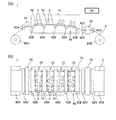
- FIG. 1A is a side view of a recording apparatus including a liquid ejection head according to an embodiment of the present disclosure
- FIG. 1B is a plan view.
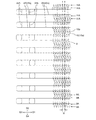
- (A) is a plan view of a head main body, which is a main part of the liquid ejection head of FIG. 1, and (b) is a plan view of (a) excluding a second flow path member.
- FIG. 3 is an enlarged plan view of a part of FIG.
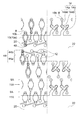
- FIG. 4 is an enlarged plan view of a part of FIG. 3.
- (A) is a schematic partial longitudinal sectional view of the head main body, and (b) is a longitudinal sectional view of another part of the head main body.
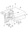
- FIG. 3 is a perspective view schematically illustrating a part of a flow path of a head body.
- FIG. 3 is a partially enlarged plan view of a first common channel and a bypass channel.
- FIG. 7 is a partially enlarged plan view of a second common channel and a bypass channel.
- FIG. 1A illustrates a color inkjet printer 1 (hereinafter, may be simply referred to as a printer) which is a recording apparatus including a liquid ejection head 2 (hereinafter, sometimes simply referred to as a head) according to an embodiment of the present disclosure.
- a printer which is a recording apparatus including a liquid ejection head 2 (hereinafter, sometimes simply referred to as a head) according to an embodiment of the present disclosure.
- FIG. 1 (b) is a schematic plan view.
- the printer 1 moves the printing paper P relative to the head 2 by transporting the printing paper P as a recording medium from the paper feeding roller 80A to the collection roller 80B.
- the paper feed roller 80A, the collection roller 80B, and various rollers described below constitute a moving unit 85 that relatively moves the print paper P and the head 2.
- the control unit 88 controls the head 2 based on print data or the like, which is data of images, characters, and the like, to discharge liquid toward the printing paper P, land droplets on the printing paper P, and perform printing.
- the recording such as printing is performed on the paper P.
- the head 2 is fixed to the printer 1, and the printer 1 is a so-called line printer.
- the printer 1 is a so-called line printer.
- a so-called serial printer which alternately conveys the printing paper P.
- Each frame 70 is provided with five holes (not shown), and five heads 2 are mounted on the respective holes.
- the five heads 2 mounted on one frame 70 constitute one head group 72.
- the printer 1 has four head groups 72, and a total of 20 heads 2 are mounted.
- the head 2 mounted on the frame 70 is configured such that a portion for discharging the liquid faces the printing paper P.
- the distance between the head 2 and the printing paper P is, for example, about 0.5 to 20 mm.
- the # 20 heads 2 may be directly connected to the control unit 88, or may be connected via a distribution unit that distributes print data therebetween.
- the control unit 88 may send print data to one distribution unit, and one distribution unit may distribute the print data to the 20 heads 2. Further, for example, the control unit 88 distributes print data to four distribution units corresponding to the four head groups 72, and each distribution unit distributes print data to the five heads 2 in the corresponding head group 72. Is also good.
- the head 2 has an elongated shape that is elongated in the direction from the near side to the back side in FIG. 1A and the up and down direction in FIG. 1B.
- the three heads 2 are arranged in a direction intersecting the transport direction of the printing paper P, for example, in a direction substantially orthogonal to the transport direction, and the other two heads 2 are arranged in the transport direction.
- one head is arranged between each of the three heads 2.
- the heads 2 are arranged in a staggered manner.
- the heads 2 are arranged such that the printable range of each head 2 is connected in the width direction of the printing paper P, that is, in the direction intersecting the transport direction of the printing paper P, or the ends are overlapped. Printing without gaps in the width direction of the printing paper P is enabled.
- the four head groups 72 are arranged along the transport direction of the printing paper P.
- Each head 2 is supplied with liquid, for example, ink from a liquid supply tank (not shown).
- the same color ink is supplied to the heads 2 belonging to one head group 72, and the four head groups 72 can print four color inks.
- the colors of the ink ejected from each head group 72 are, for example, magenta (M), yellow (Y), cyan (C), and black (K). If such an ink is controlled and printed by the control unit 88, a color image can be printed.
- the number of the heads 2 mounted on the printer 1 may be one as long as the printable area can be printed with one head 2 in a single color.
- the number of the heads 2 included in the head group 72 and the number of the head groups 72 can be appropriately changed according to a printing target and printing conditions.
- the number of head groups 72 may be increased to perform multi-color printing. If a plurality of head groups 72 for printing in the same color are arranged and printing is performed alternately in the transport direction, the transport speed can be increased even if the heads 2 having the same performance are used. Thereby, the printing area per time can be increased.
- a plurality of head groups 72 for printing in the same color may be prepared and displaced in a direction intersecting the transport direction to increase the resolution of the printing paper P in the width direction.
- a liquid such as a coating agent may be printed by the head 2 uniformly or by patterning in order to perform a surface treatment of the printing paper P.
- the coating agent for example, in the case where a recording medium is used that hardly penetrates the liquid, one that forms a liquid receiving layer so that the liquid can be easily fixed can be used.
- the liquid permeation suppression is performed so that the bleeding of the liquid does not become too large and the liquid does not mix too much with another liquid that has landed next to the recording medium. Those that form a layer can be used.
- the coating agent may be uniformly applied by the coating machine 76 controlled by the control unit 88 in addition to printing by the head 2.
- the printer 1 performs printing on the printing paper P as a recording medium.
- the printing paper P is wound around the paper feeding roller 80A, and the printing paper P sent out from the paper feeding roller 80A passes under the head 2 mounted on the frame 70, and then moves to the next position. After passing between the two transport rollers 82C, it is finally collected by the collection roller 80B. At the time of printing, the printing paper P is transported at a constant speed by rotating the transport roller 82C, and is printed by the head 2.
- the printing paper P sent from the paper feeding roller 80A passes between the two guide rollers 82A and then passes below the coating machine 76.
- the applicator 76 applies the above-described coating agent to the printing paper P.
- the printing paper P subsequently enters the head chamber 74 in which the frame 70 on which the head 2 is mounted is stored.
- the head chamber 74 is connected to the outside at a part such as a part where the printing paper P enters and exits, but is generally a space isolated from the outside.
- control factors such as temperature, humidity, and air pressure are controlled by the control unit 88 and the like as necessary.
- the influence of disturbance can be reduced as compared with the outside where the printer 1 is installed, so that the above-described fluctuation range of the control factor can be narrower than outside.
- Five guide rollers 82B are arranged in the head chamber 74, and the printing paper P is transported on the guide rollers 82B.
- the five guide rollers 82B are arranged so that the center becomes convex toward the direction in which the frame 70 is arranged when viewed from the side.
- the printing paper P conveyed over the five guide rollers 82B has an arc shape when viewed from the side, and by applying tension to the printing paper P, the printing paper P between the respective guide rollers 82B is formed.
- One frame 70 is arranged between the two guide rollers 82B. The angle at which each frame 70 is installed is slightly changed so as to be parallel to the printing paper P conveyed thereunder.
- the printing paper P that has exited from the head chamber 74 passes between the two transport rollers 82C, passes through the dryer 78, passes between the two guide rollers 82D, and is collected by the collection roller 80B.
- the transport speed of the printing paper P is, for example, 100 m / min.
- Each roller may be controlled by the control unit 88 or may be manually operated by a person.
- the dryer 78 may perform drying in order using a plurality of drying methods, or may use a plurality of drying methods in combination. Drying methods used in such a case include, for example, blowing of hot air, irradiation of infrared rays, and contact with a heated roller. When irradiating infrared rays, infrared rays in a specific frequency range may be applied so that drying can be performed faster while reducing damage to the printing paper P.
- the time during which heat is transmitted may be increased by transporting the printing paper P along the cylindrical surface of the roller.
- the range of conveyance along the cylindrical surface of the roller is preferably at least 4 of the cylindrical surface of the roller, and more preferably at least ⁇ of the cylindrical surface of the roller.
- a UV irradiation light source may be provided instead of or in addition to the dryer 78.
- a UV irradiation light source may be arranged between each frame 70.
- the printer 1 may include a cleaning unit for cleaning the head 2.
- the cleaning unit performs cleaning by, for example, wiping or capping.
- the wiping is performed, for example, by rubbing a surface of a portion to which the liquid is discharged, for example, a discharge hole surface 4-2 (described later) with a flexible wiper to remove the liquid attached to the surface.
- the cleaning by capping is performed, for example, as follows. First, a cap is placed so as to cover a portion from which liquid is discharged, for example, the discharge hole surface 4-2 (this is referred to as capping), so that the discharge hole surface 4-2 and the cap are substantially sealed and a space is formed. Made.
- the liquid, foreign matter, and the like, which are clogged in the discharge holes 8 (described later) and have higher viscosity than the standard state, are removed.
- the liquid being washed is less likely to scatter to the printer 1 and the liquid is less likely to adhere to the printing paper P or a transport mechanism such as a roller.
- the ejection hole surface 4-2 may be further wiped. The wiping and the cleaning by capping may be performed by manually operating a wiper or a cap attached to the printer 1 or automatically by the control unit 88.
- the recording medium may be a roll-shaped cloth or the like other than the printing paper P. Further, instead of directly transporting the printing paper P, the printer 1 may directly transport the transport belt and place the recording medium on the transport belt to transport. In this way, sheets, cut cloth, wood, tiles, etc. can be used as the recording medium. Furthermore, a wiring pattern or the like of an electronic device may be printed by discharging a liquid containing conductive particles from the head 2. Further, a chemical may be produced by discharging a predetermined amount of liquid chemical or a liquid containing the chemical from the head 2 toward a reaction container or the like to cause a reaction.
- a position sensor, a speed sensor, a temperature sensor, and the like may be attached to the printer 1, and the control unit 88 may control each unit of the printer 1 according to the state of each unit of the printer 1 that can be obtained from information from each sensor.
- the temperature of the head 2 the temperature of the liquid in the liquid supply tank that supplies the liquid to the head 2
- the pressure applied to the head 2 by the liquid in the liquid supply tank, and the like indicate the discharge characteristics of the liquid to be discharged
- the drive signal for discharging the liquid may be changed according to the information.
- FIG. 2A is a plan view showing a head main body 2a which is a main part of the head 2 shown in FIG.
- FIG. 2B is a plan view showing a state where the second flow path member 6 is removed from the head main body 2a.
- FIG. 3 is an enlarged plan view of the head main body 2a in the range of the alternate long and short dash line in FIG. 2B.
- FIG. 4 is an enlarged plan view of the head main body 2a in the range of the alternate long and short dash line in FIG.
- FIG. 5A is a schematic partial longitudinal sectional view of the head main body 2a.
- FIG. 5A in order to show a state where the flow paths are connected, flow paths that do not actually exist in the same vertical cross section are drawn as if they exist in the same vertical cross section.
- FIG. 5B also illustrates a signal transmission unit 60 not illustrated in FIG. 2A.
- FIG. 6 is a perspective view schematically showing a part of the flow path in the head main body 2a.
- FIGS. 2 to 4 the flow paths and the like which are to be drawn by broken lines below the others are drawn by solid lines.
- FIG. 4 the figure is divided into right and left parts by a two-dot chain line. On the left side of the two-dot chain line, a flow path from the first common flow path 20 to the discharge hole 8 is drawn. On the right side of the two-dot chain line, a flow path from the discharge hole 8 to the second common flow path 22 is drawn.
- individual electrodes 44 and connection electrodes 46 are also illustrated.
- the head 2 may include a housing, a driver IC, a wiring board, and the like, in addition to the head main body 2a.
- the head main body 2a includes a first flow path member 4, a second flow path member 6 for supplying a liquid to the first flow path member 4, and a piezoelectric actuator in which a displacement element 50 serving as a pressurizing unit is formed. And a substrate 40.
- the head main body 2a has a flat plate shape that is long in one direction, and that direction may be referred to as a longitudinal direction.
- the second flow path member 6 serves as a support member for supporting the structure of the head main body 2a.
- the head main body 2a is fixed to the frame 70 at each of both longitudinal ends of the second flow path member 6. Is done.
- the first flow path member 4 constituting the head main body 2a has a flat plate shape, and has a thickness of about 0.5 to 2 mm.
- a plurality of pressurizing chambers 10 are arranged in a plane on a pressurizing chamber surface 4-1 which is one surface of the first flow path member 4.
- a large number of discharge holes 8 for discharging liquid are arranged in a plane direction on a discharge hole surface 4-2 of the first flow path member 4 opposite to the pressurizing chamber surface 4-1. .
- the discharge holes 8 are connected to the pressurizing chambers 10, respectively.
- the description will be made on the assumption that the pressure chamber surface 4-1 is located above the discharge hole surface 4-2.
- a plurality of first common flow paths 20 and a plurality of second common flow paths 22 are arranged in the first flow path member 4 so as to extend along the first direction.
- the first common channel 20 and the second common channel 22 may be collectively referred to as a common channel.
- At least a part of the first common flow path 20 and the second common flow path 22 are arranged so as to overlap with each other. For example, 80% or more of the widths overlap each other, or the entire widths overlap each other.
- the direction that intersects the first direction is referred to as a second direction.
- the first direction is the same direction as the longitudinal direction of the head main body 2a.
- a direction opposite to the first direction is defined as a third direction
- a direction opposite to the second direction is defined as a fourth direction.
- the first to fourth directions are indicated by D1 to D4.
- the pressurized chamber 10 is connected to the first common flow path 20 and the second common flow path 22, and is connected to the pressurized chamber 10.
- the discharge holes 8 are arranged.
- the pressurizing chambers 10 connected to the first common flow path 20 and the second common flow path 22 constitute four pressurizing chamber rows 11A, each having two rows on one side of the common flow path and two rows on both sides. I have.
- the discharge holes 8 connected to the first common flow path 20 and the second common flow path 22 constitute four discharge hole rows 9A each having two rows on one side of the common flow path and a total of two rows on both sides. I have. Since there are eight first common channels 20 and second common channels 22, there are 32 rows of pressurizing chambers 11A in total and 32 rows of discharge hole rows 9A in total.
- the first common flow path 20 and the four rows of pressurizing chambers 10 arranged on both sides thereof are connected via the first relay flow path 12.
- the second common flow channel 22 and the four rows of pressurizing chambers 10 arranged on both sides thereof are connected via the second relay flow channel 14.
- the liquid supplied to the first common flow path 20 flows into the pressurizing chambers 10 arranged along the first common flow path 20.
- a part of the liquid that has flowed into the pressurizing chamber 10 is discharged from the discharge hole 8, and another part flows into the second common flow path 22 that is arranged to overlap the first common flow path 20, and It is discharged from the flow path member 4 to the outside.
- the first common channel 20 is a channel through which the liquid supplied to the pressurizing chamber 10 flows, and can be referred to as a supply channel.
- the second common flow path 22 is a flow path through which the liquid collected from the pressurized chamber 10 flows, and can be referred to as a recovery flow path. Note that the flow of liquid supply and recovery may be reversed, including the following description.
- the first common flow path 20 is disposed so as to overlap the second common flow path 22.
- the first common flow path 20 has an opening 20b disposed at both ends in the first direction and the third direction outside the range where the first relay flow path 12 is connected. Open to the outside.
- the second common flow path 22 has both ends in the first direction and the third direction outside the range where the second relay flow path 14 is connected and outside the opening 20 b of the first common flow path 20.
- the opening 22b is disposed outside the first flow path member 4. Since the opening 22b of the second common flow path 22 disposed on the lower side is disposed outside the opening 20b of the first common flow path 20 disposed on the upper side, space efficiency is improved.
- the entirety of the second common flow path main body 22a excluding both ends is disposed below the entirety of the first common flow path main body 20a excluding both ends.
- a substantially equal amount of liquid is supplied from the opening 20b on the first direction side and the opening 20b on the third direction side of the first common flow path 20, and flows toward the center of the first common flow path 20.
- the discharge amount of the liquid from the discharge holes 8 connected to one first common flow path 20 and one second common flow path 22 is substantially constant regardless of the location, the flow of the first common flow path 20 , Slows down toward the center, and becomes 0 (zero) almost at the center.
- the flow in the second common flow channel 22 is opposite to this, and is 0 (zero) substantially at the center, and the flow becomes faster toward the outside.
- the discharge amount of the liquid from the discharge holes 8 connected to one first common flow path 20 and one second common flow path 22 has various distributions.
- the location where the flow becomes 0 (zero) is on the first direction side from the center.
- the discharge amount from the discharge hole 8 in the third direction is large, the place where the flow becomes 0 (zero) is on the third direction side from the center.
- the location where the flow becomes 0 (zero) moves due to the change in the distribution of ejection depending on what is recorded.
- the pressure applied to the portion of the first relay flow path 12 connected to the first common flow path 20 on the first common flow path 20 side is affected by the pressure loss and the first relay flow path 12 Varies depending on the position where is connected (mainly the position in the first direction).
- the pressure applied to the portion on the side of the second relay flow path 14 connected to the second common flow path 22 is affected by the pressure loss, and the position where the second relay flow path 14 is connected to the second common flow path 22 (main Position in the first direction). If the pressure of the liquid in one discharge hole 8 is set to approximately 0 (zero), the above-mentioned pressure change changes symmetrically, so that the pressure of the liquid in all the discharge holes 8 can be set to approximately 0 (zero).
- the lower surface of the first common flow path 20 is a damper 28A.
- the surface of the damper 28A opposite to the surface facing the first common flow path 20 faces the damper chamber 29A.
- the damper chamber 29 ⁇ / b> A contains gas such as air, and its volume changes according to the pressure applied from the first common channel 20.
- the damper 28A can vibrate by changing the volume of the damper chamber 29A, and the vibration can be attenuated to attenuate the pressure fluctuation generated in the first common flow path 20.
- pressure fluctuation such as resonance of the liquid in the first common flow path 20 can be reduced.
- the lower surface of the second common flow path 22 is a damper 28B.
- the surface of the damper 28B opposite to the surface facing the second common flow path 22 faces the damper chamber 29B.
- the discharge holes 8 are arranged at an interval of 50 dpi (about 25.4 mm / 50).
- the second flow path member 6 is joined to the pressurizing chamber surface 4-1 of the first flow path member 4, and is connected to the first integrated flow path 24 for supplying liquid to the first common flow path 20 and the second common flow path 24.
- the thickness of the second flow path member 6 is larger than that of the first flow path member 4, and is about 5 to 30 mm.
- the second flow path member 6 is joined in a region of the pressurizing chamber surface 4-1 of the first flow path member 4 where the piezoelectric actuator substrate 40 is not connected. More specifically, they are joined so as to surround the piezoelectric actuator substrate 40. By doing so, it is possible to prevent a part of the discharged liquid from adhering to the piezoelectric actuator substrate 40 as a mist. Further, since the first flow path member 4 is fixed at the outer periphery so as to surround the piezoelectric actuator substrate 40, the first flow path member 4 vibrates in accordance with the driving of the displacement element 50, thereby reducing the resonance that occurs. it can.
- an opening 24b that is open on the upper surface of the second flow path member 6 is disposed.
- the first integrated flow path 24 is branched into two in the middle, one is connected to the opening 20b of the first common flow path 20 on the third direction side, and the other is the first common flow path on the first direction side. 20 are connected to the opening 20b.
- an opening 26b that is open on the upper surface of the second flow path member 6 is arranged.
- the second integrated flow path 26 is branched into two on the way, one of which is connected to the opening 22b of the second common flow path 22 in the first direction, and the other is the second common flow path in the third direction. 22 is connected to the opening 22b.
- the second flow path member 6 is provided with a through-hole 6 a vertically penetrating the second flow path member 6.
- a signal transmission unit 60 such as an FPC (Flexible Printed Circuit) that transmits a drive signal for driving the piezoelectric actuator substrate 40 is passed through the through hole 6a.
- the cross-sectional area of the first integrated channel 24 is increased. Accordingly, a difference in pressure loss due to a difference in a position where the first integrated flow path 24 and the first common flow path 20 are connected can be reduced.
- the flow resistance of the first integrated flow path 24 is preferably set to 1/100 or less of the first common flow path 20.
- the flow path resistance of the first integrated flow path 24 is, more precisely, a flow path resistance in a range connected to the first common flow path 20 in the first integrated flow path 24.
- the cross-sectional area of the second integrated channel 26 is increased. Accordingly, the difference in pressure loss due to the difference in the position where the second integrated flow path 26 and the second common flow path 22 are connected can be reduced.
- the flow resistance of the second integrated flow path 26 is preferably set to 1/100 or less of the second common flow path 22.
- the flow path resistance of the second integrated flow path 26 is, more precisely, a flow path resistance in a range connected to the first integrated flow path 24 in the second integrated flow path 26.
- the first integrated flow path 24 is disposed at one end of the second flow path member 6 in the short direction
- the second integrated flow path 26 is disposed at the other end of the second flow path member 6 in the short direction
- Each of the flow paths is directed toward the first flow path member 4 and is connected to the first common flow path 20 and the second common flow path 22, respectively.
- the cross-sectional area of the first integrated channel 24 and the second integrated channel 26 can be increased, and the channel resistance can be reduced.
- the outer periphery of the first flow path member 4 is fixed by the second flow path member 6, so that the rigidity can be increased.
- the through hole 6a through which the signal transmission unit 60 passes can be provided.
- a groove serving as the first integrated flow path 24 (first integrated flow path main body 24a) and a groove serving as the second integrated flow path 26 (second integrated flow path main body 26a) are provided on the lower surface of the second flow path member 6.
- Part of the lower surface of the groove serving as the first integrated channel main body 24 a is closed by the upper surface of the first channel member 4.
- the other part of the lower surface is connected to the opening 20b of the first common flow path 20.
- a part of the lower surface of the groove serving as the second integrated channel main body 26 a is closed by the upper surface of the first channel member 4.
- the other portion of the lower surface is connected to the opening 22b of the second common flow channel 22.
- a damper may be provided in the first integrated flow path 24 and the second integrated flow path 26 so that the supply or discharge of the liquid is stabilized with respect to the fluctuation of the discharge amount of the liquid. Further, by providing a filter inside the first integrated channel 24 and the second integrated channel 26 and between the first common channel 20 and the second common channel 22, foreign matter and air bubbles can be reduced to the first common channel 20 or the second common channel 22. It may be difficult to enter the flow path member 4.
- the upper surface of the second flow path member 6 is closed by a metal casing or the like.
- the signal transmission unit 60 is electrically connected to, for example, a wiring board housed in a housing.
- the wiring board and the control unit 88 are electrically connected by a cable or the like.
- a driver IC for driving the displacement element 50 may be mounted on the signal transmission unit 60. By bringing the driver IC into contact with a metal housing or a member that allows heat to be easily transmitted to the housing, heat generated by the driver IC can be released to the outside.
- the piezoelectric actuator substrate 40 including the displacement elements 50 is joined to the pressure chamber surface 4-1 which is the upper surface of the first flow path member 4, so that each displacement element 50 is positioned on the pressure chamber 10. Are located.
- the piezoelectric actuator substrate 40 occupies a region having substantially the same shape as the pressure chamber group constituted by the pressure chambers 10.
- the opening of each pressurizing chamber 10 is closed by joining the piezoelectric actuator substrate 40 to the pressurizing chamber surface 4-1 of the first flow path member 4.
- the piezoelectric actuator substrate 40 has a rectangular shape that is long in the same direction as the head main body 2a.
- the signal transmission unit 60 that supplies a signal to each displacement element 50 is connected to the piezoelectric actuator substrate 40.
- the second flow path member 6 has a through hole 6a vertically penetrating at the center, and the signal transmission unit 60 is electrically connected to the control unit 88 through the through hole 6a.
- the signal transmission unit 60 has a shape that extends in the short direction from the end of one long side of the piezoelectric actuator substrate 40 to the end of the other long side, and the wiring arranged in the signal transmission unit 60 extends in the short direction. If they extend along the length and are arranged in the longitudinal direction, the distance between the wirings can be increased.
- the first flow path member 4 has a laminated structure in which a plurality of plates are laminated.
- a plate 4a is arranged on the side of the pressure chamber surface 4-1 of the first flow path member 4, and plates 4b to 4o are sequentially stacked below the plate 4a.
- the plate 4a in which the hole serving as the side wall of the pressurizing chamber 10 is formed is called a cavity plate 4a, and the plates 4f, 4g, 4h, 4i, 4l, and 4m in which the hole serving as the side wall of the common flow path is formed.
- manifold plates 4f, 4g, 4h, 4i, 4l, and 4m are referred to as manifold plates 4f, 4g, 4h, 4i, 4l, and 4m
- the plate 4o in which the discharge holes 8 are opened may be referred to as a nozzle plate 4o.
- Each plate has a large number of holes and grooves.
- the holes and grooves can be formed by, for example, forming each plate with metal and etching. When the thickness of each plate is about 10 to 300 ⁇ m, the accuracy of forming holes can be increased.
- the plates are aligned and laminated so that these holes communicate with each other to form a flow path such as the first common flow path 20.
- the pressurizing chamber main body 10a is opened in the pressurizing chamber surface 4-1 of the first flat channel member 4, and the piezoelectric actuator substrate 40 is joined thereto.
- an opening 20b for supplying liquid to the first common flow path 20 and an opening 22b for collecting liquid from the second common flow path 22 are opened in the pressurizing chamber surface 4-1.
- a discharge hole 8 is opened on a discharge hole surface 4-2 of the first flow path member 4 opposite to the pressurizing chamber surface 4-1.
- the pressurizing chamber 10 includes a pressurizing chamber main body 10a facing the displacement element 50, and a partial flow path 10b connecting the pressurizing chamber main body 10a and the discharge hole.
- the pressurizing chamber main body 10a is formed in the cavity plate 4a, and the partial flow path 10b is formed by overlapping holes formed in the plates 4b to 4n, and further closed by the nozzle plate 4o (the portion other than the discharge holes 8). It's made up.
- the first relay channel 12 is connected to the pressurizing chamber main body 10a, and the first relay channel 12 is connected to the first common channel 20.
- the first relay channel 12 includes a circular hole penetrating the plate 4b, an elongated penetrating groove extending in the plane direction of the plate 4c, and a circular hole penetrating the plates 4d and 4e.
- the second relay flow path 14 is connected to the partial flow path 10b, and the second relay flow path 14 is connected to the second common flow path 22.
- the second relay flow path 14 includes an individual flow path 14a connected to one pressurization chamber 10 and a connection flow path 14b connected to another pressurization chamber 10.
- the two individual flow paths 14a respectively connected to the two pressurizing chambers 10 are combined into one connection flow path 14b, and then connected to the second common flow path 22.
- the number of connection flow paths 14b connected to one second common flow path 22 is plural.
- the number of the connection channels 14 b connected to one second common channel 22 is half the number of the pressurizing chambers 10 connected to one second common channel 22.
- the space efficiency is improved by connecting the plurality of individual flow paths 14a to the second common flow path 22 after being bundled in the connection flow path 14b.
- the number of the individual flow paths 14a connected to the connection flow path 14b may be three or more.
- two second relay channels 14 may be provided for the two pressurizing chambers 10 and may be regarded as sharing one connecting channel 14b, And one second relay flow path 14 may be regarded as having two individual flow paths 14a.
- the former method is mainly used. Is expressed.
- the first common flow path 20 has holes formed in the plates 4f to 4i overlapped, and the upper side is closed by a plate 4e and the lower side is closed by a plate 4j.
- the second common flow path 22 has holes formed in the plates 41 and 4m overlapped, and the upper side is closed by a plate 4k and the lower side is closed by a plate 4n.
- the liquid supplied to the first integrated flow path 24 enters the pressurizing chamber 10 through the first common flow path 20 and the first relay flow path 12 in order, and a part of the liquid is discharged. Discharged from the hole 8.
- the liquid that has not been discharged passes through the second relay flow path 14, enters the second common flow path 22, enters the second integrated flow path 26, and is discharged to the outside of the head main body 2a.
- the piezoelectric actuator substrate 40 has a laminated structure including two piezoelectric ceramic layers 40a and 40b that are piezoelectric bodies. Each of these piezoelectric ceramic layers 40a and 40b has a thickness of about 20 ⁇ m. That is, the thickness from the upper surface of the piezoelectric ceramic layer 40a to the lower surface of the piezoelectric ceramic layer 40b of the piezoelectric actuator substrate 40 is about 40 ⁇ m.
- the thickness ratio of the piezoelectric ceramic layer 40a to the piezoelectric ceramic layer 40b is set to 3: 7 to 7: 3, preferably 4: 6 to 6: 4.
- Each of the piezoelectric ceramic layers 40a and 40b extends so as to straddle the plurality of pressure chambers 10.
- the piezoelectric ceramic layers 40a and 40b for example, strength with a dielectric, lead zirconate titanate (PZT), NaNbO 3 system, BaTiO 3 system, (BiNa) NbO 3 system, such as BiNaNb 5 O 15 system Made of ceramic material.
- PZT lead zirconate titanate
- NaNbO 3 system NaNbO 3 system
- BaTiO 3 system BaTiO 3 system
- BiNa NbO 3 system such as BiNaNb 5 O 15 system Made of ceramic material.
- the piezoelectric ceramic layer 40b functions as a diaphragm, and does not directly undergo piezoelectric deformation.
- a ceramic or metal plate having no piezoelectricity may be used instead of the piezoelectric ceramic layer 40b.
- the piezoelectric actuator substrate 40 has a common electrode 42 made of a metal material such as Ag-Pd and an individual electrode 44 made of a metal material such as Au.
- the thickness of the common electrode 42 is about 2 ⁇ m, and the thickness of the individual electrode 44 is about 1 ⁇ m.
- the individual electrodes 44 are arranged at positions on the upper surface of the piezoelectric actuator substrate 40 that face the respective pressure chambers 10.
- the individual electrode 44 has a planar shape slightly smaller than the main body 10a of the pressurizing chamber, and has an approximately similar shape to the main body 10a of the pressurizing chamber, and an extraction electrode drawn from the main body 44a of the individual electrode. 44b.
- a connection electrode 46 is formed at a portion of one end of the extraction electrode 44b that is extracted outside a region facing the pressurizing chamber 10.
- the connection electrode 46 is, for example, a conductive resin containing conductive particles such as silver particles, and is formed with a thickness of about 5 to 200 ⁇ m.
- the connection electrode 46 is electrically connected to an electrode provided on the signal transmission unit 60.
- a drive signal is supplied to the individual electrode 44 from the control unit 88 through the signal transmission unit 60.
- the drive signal is supplied at a constant period in synchronization with the transport speed of the printing paper P.
- the common electrode 42 is formed in a region between the piezoelectric ceramic layer 40a and the piezoelectric ceramic layer 40b over substantially the entire surface in the surface direction. That is, the common electrode 42 extends so as to cover all the pressurizing chambers 10 in the region facing the piezoelectric actuator substrate 40.
- the common electrode 42 is formed on a surface electrode for common electrode (not shown) formed at a position avoiding the electrode group including the individual electrodes 44 on the piezoelectric ceramic layer 40a, and a through conductor formed through the piezoelectric ceramic layer 40a. Are connected via. Further, the common electrode 42 is grounded via a common electrode surface voltage, and is held at the ground potential.
- the common electrode surface electrode is directly or indirectly connected to the control unit 88 in the same manner as the individual electrode 44.
- the portion of the piezoelectric ceramic layer 40a sandwiched between the individual electrode 44 and the common electrode 42 is polarized in the thickness direction, and becomes a unimorph displacement element 50 that is displaced when a voltage is applied to the individual electrode 44. I have. More specifically, when an electric field is applied to the piezoelectric ceramic layer 40a in the direction of its polarization by setting the individual electrode 44 to a potential different from that of the common electrode 42, the portion to which the electric field is applied is distorted by the piezoelectric effect.
- the displacement element 50 is driven (displaced) by a drive signal supplied to the individual electrode 44 via a driver IC or the like under the control of the control unit 88.
- the liquid can be ejected by various drive signals.
- a so-called pull driving method will be described.
- the individual electrode 44 is previously set at a higher potential than the common electrode 42 (hereinafter, referred to as a high potential), and the individual electrode 44 is once set to the same potential as the common electrode 42 (hereinafter, referred to as a low potential) every time there is a discharge request. Thereafter, at a predetermined timing, the potential is increased again.
- the piezoelectric ceramic layers 40a and 40b return (start) to the original (flat) shape, and the volume of the pressurizing chamber 10 is initialized (the potential of both electrodes is different). State). Thereby, a negative pressure is applied to the liquid in the pressurizing chamber 10. Then, the liquid in the pressurized chamber 10 starts to vibrate at the natural vibration cycle.
- the volume of the pressurizing chamber 10 starts to increase, and the negative pressure gradually decreases.
- the volume of the pressurizing chamber 10 becomes maximum and the pressure becomes almost zero.
- the volume of the pressurizing chamber 10 starts to decrease, and the pressure increases.
- the individual electrode 44 is set to a high potential.
- the first applied vibration and the second applied vibration overlap, and a greater pressure is applied to the liquid. This pressure propagates in the partial flow path 10b and causes the liquid to be discharged from the discharge hole 8.
- a droplet can be discharged by supplying a drive signal of a pulse that keeps a low potential for a certain period with respect to the high potential to the individual electrode 44.
- this pulse width is set to AL (Acoustic Length), which is half the period of the natural oscillation period of the liquid in the pressurizing chamber 10, the discharge speed and the discharge amount of the liquid can be maximized in principle.
- AL Acoustic Length
- the natural oscillation period of the liquid in the pressurizing chamber 10 is greatly influenced by the physical properties of the liquid and the shape of the pressurizing chamber 10.
- the physical properties of the piezoelectric actuator substrate 40 and the flow path connected to the pressurizing chamber 10 are different. Is also affected by the characteristics of
- the first common channel 20 has a larger cross-sectional area to supply the liquid to be discharged.
- the cross-sectional area of the second common flow channel 22 should also be somewhat large.
- the width of the head body 2a in the short direction increases, and the range in which the ejection holes 8 are distributed in the short direction also increases. If the distribution range of the ejection holes 8 in the short direction is widened, the printing accuracy is greatly reduced when the installation angle of the head 2 is shifted so as to rotate in the plane direction, which is not desirable.
- the arrangement interval of the common flow channel may be reduced. If the space efficiency of the channels arranged between the common channels is improved, the arrangement interval of the common channels can be reduced. Since the second relay flow path 14 is a flow path connected to the vicinity of the discharge hole 8 of the pressurizing chamber 10, if the space efficiency of the arrangement of the second relay flow path 14 is improved, the arrangement interval of the common flow path is reduced. it can.
- the cross-sectional area and the length of the second relay channel 14 are preferably substantially the same in design. Further, it is desirable that the second relay channel 14 has channel characteristics suitable for discharge, and has a cross-sectional area and a length suitable for achieving the channel characteristics. Simply for improving the space efficiency, for example, a flow path that connects the shortest distance with a straight line may be provided, but it is difficult for such a flow path to have the flow path characteristics as described above. is there.
- the second common flow path Connect to 22 More specifically, after the individual flow paths 14a connected to only one pressurizing chamber 10 are bundled as the connection flow paths 14b, the individual flow paths 14a are connected to the second common flow path 22. In other words, a plurality of individual flow paths 14a are connected to one connection flow path 14b. That is, a plurality of individual flow paths 14a are connected to the upstream end of the connection flow path 14b constituting the second relay flow path 14, and the second common flow path 22 is connected to the downstream end of the connection flow path 14b. Connected configuration. Thereby, the space required for disposing the flow paths can be reduced as compared with the case where completely individual flow paths are provided.
- the pressurizing chamber 10 And the second common flow path 22 are completely connected by a separate second relay flow path, and the second relay flow path is assumed to have the shortest distance.
- the second relay flow path connected to the pressurized chamber 10 far from the second common flow path 22 is the second relay flow path connected to the pressurized chamber 10 closer to the second common flow path 22. It is longer than the flow path. As a result, the two flow path characteristics are different.
- the second common flow path 22 While making the second relay channel 14 connected to the close pressurizing chamber 10 longer, the longer channel can be efficiently arranged.
- connection flow path 14b is longer than the individual flow path 14a, that is, the higher the proportion of the connection flow path 14b in the second relay flow path 14, the higher the space efficiency.
- a part of the pressure at which the liquid is discharged from the plurality of pressurizing chambers 10 is transmitted to the liquid in the second common flow path 22, causing complicated pressure vibration.
- a part of the pressure vibration is transmitted to the pressurizing chamber 10 and may affect the subsequent discharge. If the pressures from the two pressurizing chambers 10 are combined in the connection channel 14b before being transmitted to the second common channel 22, the complexity of the pressure oscillation in the second common channel 22 can be reduced. The effect on subsequent ejection can be reduced. If the Newtonian fluid is filled in the complete columnar flow path, the pressure waves are transmitted independently, but if the flow path is an actual flow path and a real liquid, the pressures affect each other.
- the connection flow path 14b is preferably longer than the individual flow path 14a so that the synthesis of pressure proceeds.
- the discharge pressure generated in one pressurizing chamber 10 passes through an individual flow path 14a connected to the pressurizing chamber 10 and then passes through an individual flow path 14a connected to another pressurizing chamber 10, and To the pressure chamber 10.
- the flow resistance of the individual flow path 14a is larger than the flow resistance of the connection flow path 14b.
- connection flow path 14b After bundling a plurality of individual flow paths 14a to form a connection flow path 14b, by connecting to the second common flow path 22, space efficiency can be improved.
- the second relay flow path 14 connected to the discharge hole 8 arranged in the first gap region can be accommodated and arranged in the first gap region.
- connection flow path 14b After bundling a plurality of individual flow paths 14a to form a connection flow path 14b, by connecting to the second common flow path 22, space efficiency can be improved.
- the second relay flow path 14 connected to the discharge hole 8 arranged in the second gap area can be accommodated and arranged in the second gap area.
- the second relay flow path 14 is connected near the discharge hole 8 of the partial flow path 10b so that the liquid near the discharge hole 8 does not stay.
- the second relay flow path 14 is disposed closer to the discharge hole surface 4-2 than the first common flow path 20 is.
- a plurality of individual flow paths 14a are bundled to form a connection flow path 14b, and then connected to the second common flow path 22, so that space efficiency can be improved, and the second common flow path 22 and the second relay
- the flow path 14 can be arranged closer to the discharge hole surface 4-2 than the first common flow path 20 is.
- the entirety of the second common flow path 22 except for both ends and the entirety of the second relay flow path 14 can be arranged closer to the discharge hole surface 4-2 than the first common flow path 20 is.
- the individual channel 14a includes a first portion 14aa directly connected to the pressurizing chamber 10, and a second portion 14ab connecting the first portion 14aa and the connection channel 14b.
- the first portion 14aa is configured by closing a hole or a groove arranged on one plate 4n with a plane portion of the other plates 4m and 4o.
- the second portion 14ab is formed such that holes or grooves arranged in a plate 4m different from the plate 4n in which holes or grooves constituting the first portion 14aa are arranged are formed by plane portions of the other plates 4l and 4n. It is made up of blockages.
- the flow path resistance per unit length of the first part 14aa is larger than the flow path resistance per unit length of the second part 14ab. This makes it difficult for the pressure from the pressurizing chamber 10 to be transmitted to the second relay channel 14 and makes it difficult for the pressure oscillation in the pressurizing chamber 10 to be complicated.
- the first portion 14aa is directly connected to the pressurizing chamber 10, the reflection of the pressure wave mainly occurs at the connection portion. As a result, the pressure oscillation in the pressurizing chamber 10 becomes relatively simple, and it becomes relatively easy to perform the next ejection in accordance with the pressure oscillation.
- the plate 4m is thicker than the plate 4n.
- the first portion 14aa can satisfy necessary flow path characteristics (flow path resistance and the like).
- the individual flow paths 14a can be connected to each other by the second part 14ab having a larger cross-sectional area than the first part 14aa and having a small influence of the flow path characteristics on the individual flow paths 14a.
- the plate 4m is a plate on which holes or grooves are arranged to be the second common flow path 22, the number of required plates can be reduced. Further, by making the plate 4n thinner than the plate 4m, the AL of the pressurizing chamber 10 can be shortened, and the head 2 can be driven in a short cycle.
- the angle formed by the individual flow paths 14a is smaller than the angle formed by the individual flow path 14a and the connection flow path 14b. .
- the angle formed by the individual channels 14a is about 80 degrees.
- the angle formed between the individual flow path 14a and the connection flow path 14b is substantially 90 degrees because the connection flow path 14b is connected to the individual flow path 14a so as to rise upward. Therefore, the magnitude relationship between those angles is as described above.
- the pressure transmitted from one individual flow path 14a is more easily transmitted to the connection flow path 14b than to the other individual flow path 14a.
- the pressure propagation generated between the pressurized chambers 10 connected via each other can be reduced.
- the above-described condition is satisfied in both of the two individual flow paths 14a. However, even if only one individual flow path 14a is satisfied, the above-described effect is obtained for the individual flow path 14a. is there. If all the individual flow paths 14a are satisfied, the above-described effects are obtained for all the individual flow paths 14a.
- the first flow path member 4 has a bypass flow path 16 connecting the first common flow path 20 and the second common flow path 22.
- the pressurizing chamber 10 also connects the first common channel 20 and the second common channel 22.
- the bypass flow path 16 is connected to the first common flow path 20 and the second common flow path 22 so as to be parallel to the pressurizing chamber 10.
- the parallel is a parallel connection (parallel of series connection and parallel connection), and a parallel spatial relationship (extends in parallel in the same direction). State) is not.
- the bypass referred to here does not necessarily mean a detour (detour), but includes a shortcut. That is, the path from the first common flow path 20 to the second common flow path 22 via the bypass flow path 16 is connected to the second common flow path 22 from the first common flow path 20 via the pressurizing chamber 10. It may be shorter than the path leading to.
- the bypass flow path 16 has one end connected to the first common flow path 20 and the other end connected to the second relay flow path 14. That is, the other end of the bypass flow path 16 is connected to the second common flow path 22 via the connection flow path 14b.
- the bypass flow path 16 can be regarded as sharing the connection flow path 14b with the second relay flow path 14 (the bypass flow path 16 includes the connection flow path 14b). In the description of the embodiment, the bypass flow path 16 is expressed as not including the connection flow path 14b.
- the unit flow path 18 includes one first common flow path 20 and one second common flow path 22, a plurality of first relay flow paths 12 connecting the two, and a plurality of pressurizing chambers. 10, a plurality of second relay flow paths 14 and a plurality of bypass flow paths 16, and a plurality of discharge holes 8 connected to the plurality of pressurizing chambers 10 included in the unit flow path 18.
- FIGS. 7 and 8 are plan views for explaining the connection position of the bypass flow path 16 in the flow direction of the common flow path.
- FIG. 7 shows a first common channel 20, a plurality of first relay channels 12, and a plurality of bypass channels 16 for one unit channel 18.
- FIG. 8 shows a second common flow path 22, a plurality of second relay flow paths 14 (more specifically, connection flow paths 14b), and a plurality of bypass flow paths 16 for one unit flow path 18.
- one unit channel 18 will be described, but the same may be applied to other unit channels 18.
- the first common flow path 20 is connected to (directly) the first connection flow paths 12 by the first connection area. 20e, and a first non-connection area 20f that is not (directly) connected to the plurality of first relay channels 12.
- the second common flow path 22 is connected (directly) to the plurality of second relay flow paths 14. It has two connection regions 22e and a second non-connection region 22f that is not (directly) connected to the plurality of second relay channels 14.
- bypass flow path 16 includes a first connection area 20e and a second connection area 22e (strictly, a connection flow path 14b connected to the second connection area 22e. , And so on.).
- the plurality of bypass channels 16 may include the bypass channel 16 connected to the first non-connection region 20f and / or the second non-connection region 22f.
- first connection region 20e and the second connection region 22e may be appropriately defined. For example, specifically, it is as follows.
- the first connection region 20e and the first non-connection region 20f pass through the first common flow path 20 in the flow direction (in other words, the longitudinal direction or the direction in which the ink flows; the second common flow path). 22 and the like.)).
- the second connection region 22e and the second non-connection region 22f are regions that divide the second common flow channel 22 in the flow direction.
- the first common flow path 20 has a plurality of first openings 20h individually connected to the plurality of first relay flow paths 12.
- the plurality of first openings 20h are distributed in the flow direction of the first common flow path 20. More specifically, the plurality of first openings 20h are arranged in the flow path direction in one or more rows (four rows in the illustrated example). In such a configuration, the first opening 20h located on the most one side (left side in the drawing) in the flow path direction is defined as a first opening 20h-A. Further, the first opening 20h located on the other side (right side in the drawing) in the flow path direction is defined as a first opening 20h-B.
- the portion from the position of the first opening 20h-A to the position of the first opening 20h-B may be the first connection region 20e.
- the position of the first opening 20h-A may be, for example, based on the edge of the first opening 20h-A on the one side (left side in the drawing).
- the position of the first opening 20h-B may be based on, for example, the edge of the first opening 20h-B on the other side (right side in the drawing).
- the second common flow path 22 has a plurality of second openings 22h individually connected to the plurality of second relay flow paths 14.
- the plurality of second openings 22 h are distributed in the flow direction of the second common flow path 22. More specifically, the plurality of second openings 22h are arranged in the flow direction in one or more rows (two rows in the illustrated example).
- the second opening 22h located at the most one side (left side in the drawing) in the flow path direction is defined as a second opening 22h-A.
- the second opening 22h located on the other side (the right side in the drawing) in the flow path direction is defined as a second opening 22h-B.
- the area from the position of the second opening 22h-A to the position of the second opening 22h-B may be used as the second connection region 22e.
- the position of the second opening 22h-A may be based on, for example, the edge of the second opening 22h-A on the one side (left side in the drawing).
- the position of the second opening 22h-B may be based on, for example, the edge of the second opening 22h-B on the other side (right side in the drawing).
- first non-connection region 20f the outside of both sides of the first openings 20h-A and 20h-B may be regarded as the first non-connection region 20f.
- outer sides on both sides of the second openings 22h-A and 22h-B may be regarded as the second non-connection regions 22f.
- the first openings 20h-A and / or the first openings 20h-B are located at the ends of the first common flow path 20, so that both sides of the first connection region 20e and / or It is also possible not to provide the first non-connection region 20f on one side.
- the first connection region 20e may be a part of the first common flow channel 20 as in the embodiment, or may be the entire first common flow channel unlike the embodiment. Good.
- the length (the flow direction) of the first non-connection region 20f is determined by the distance between the adjacent first openings 20h in each row as in the embodiment ( Alternatively, it may be longer than the pitch Pt), and unlike the embodiment, may be shorter than the distance between the adjacent first openings 20h in each row.
- the first non-connection region 20f has been described, the same applies to the second non-connection region 22f.
- the first common flow path 20 has a configuration having both ends. Therefore, as described above, the first openings 20h-A and 20h-B are located at both ends in the flow direction of the first common flow path 20 among the plurality of first openings 20h. May be. However, although not particularly shown, the first common flow path may be annular. Also in this case, the position of the opening corresponding to the opening 20b for supplying the ink to the first common flow path 20 is regarded as the end of the first common flow path, so that the first opening closest to the end may be specified. . Similarly, regarding the second common flow path 22, the position of the opening corresponding to the opening 22b may be regarded as the end of the second common flow path, and the second opening closest to the end may be specified.
- the first non-connection region may be provided at a position apart from the opening corresponding to the opening 20b.
- a first non-connection region may be provided in the folded portion and its periphery.
- the specification of the first opening (20h-A / 20h-B) defining the end of the first connection region and the determination of the presence or absence of the first non-connection region may be rationally performed.
- the first connection region is usually a straight line parallel to the pressurizing chamber row (discharge hole row). Therefore, the first opening closest to the folded portion may be regarded as the first opening located at the end of the first connection region. That is, even if there is a conventional technique in which a return flow path is provided with a bypass flow path that connects the first common flow path and the second common flow path, the bypass flow path is the bypass flow path of the present embodiment. It does not correspond to the road 16.
- the plurality of first openings are basically arranged at a constant pitch (a constant gap from another viewpoint).
- the pitch in the channel direction is constant.
- a region from one end to the other of the plurality of first openings at the constant pitch may be regarded as a first connection region.
- a region between two first openings adjacent to each other in the flow direction is a first non-connection region. May be determined.
- the pitch may be measured, for example, by a length along the first common flow path (the pitch of the second opening and the length of the bypass flow path 16). The same applies to pitch and the like.).
- the change has a periodicity.
- the pitch in the flow direction of the first common flow path 20 may have periodicity, or one row of the first openings 20h. May have periodicity in the change of pitch.
- the pitch is larger than other pitches at a very small portion (for example, 1 to 4 locations in the flow path direction), and the periodicity is broken, a relatively large pitch is formed.
- a region between two first openings adjacent to each other in the flow channel direction may be determined as a first non-connection region.
- the pitch becomes extremely larger (eg, 5 times or more) than other pitches in only a small part (for example, 1 to 4 places in the flow direction). If so, the region between the two first openings adjacent to each other in the flow path direction and constituting the extremely large pitch may be determined as a non-connection region.
- the plurality of bypass passages 16 are arranged, for example, on both sides of the first common passage 20 and the second common passage 22 along the flow direction of these common passages.
- Two flow path rows 17A are configured.
- the plurality of bypass channels 16 have the same shape as each other.
- the shape of the bypass flow passage 16 is, for example, a line-symmetrical shape with the center line of the common flow passage as a symmetric axis in a plan view (an example shown), or The shape is 180 ° rotationally symmetric in plan view.
- each flow channel row 17A the bypass flow channels 16 are arranged at a constant pitch, for example.
- the pitch size of the bypass flow channel 16 is the same between the two flow channel rows 17A on both sides of the common flow channel.
- the position of the bypass flow path 16 between the two flow path rows 17A may be shifted by an appropriate distance (approximately a half pitch in the illustrated example) or may be the same.
- the size of the pitch of the plurality of bypass channels 16 in one flow channel row 17A is, for example, equal to the size of the pitch of the pressurizing chambers 10 in one pressurizing chamber row 11A.
- two pressurization chamber rows 11A and one flow path row 17A are provided on one side of the common flow path.
- a channel 16 is provided.
- each passage row 17A the plurality of bypass passages 16 are regularly arranged along a common passage. (They are arranged according to certain rules.)
- the regularity of arrangement of the plurality of bypass flow passages 16 is the same.
- the position (phase of the cycle) of the bypass flow path 16 between the plurality of flow rows 17A may be shifted from each other (the illustrated example).
- the plurality of bypass passages 16 are regularly arranged by paying attention to each passage row 17A, in the illustrated example, a plurality of bypass passages 16 (two in this case) connected to the same common passage are described. ), The plurality of bypass channels 16 can be regarded as being regularly arranged in the channel direction of the common channel.
- the plurality of bypass passages 16 When the plurality of bypass passages 16 are arranged regularly, they may be arranged in the following manner, although not specifically shown, in addition to the above-described manner of being arranged at a constant pitch.
- the plurality of bypass passages 16 may be arranged in a manner in which the pitch changes periodically. Specifically, for example, on one side of the common flow channel, two types of bypass flow channels having different shapes may be alternately arranged in approximately one row, and two types of pitches may be present alternately. However, in this case, two types of flow channel rows are provided, and the pitch may be considered to be constant in one type of flow channel row. Examples of the two types of bypass flow paths having different shapes include a shape that is line-symmetric with respect to a symmetry axis that is orthogonal to the common flow path in a plan view, and a shape that is not symmetric.
- the pitch may be, for example, a distance between the centers of gravity with respect to the geometric centers of gravity of the bypass passages 16.
- the pitch may be measured with reference to a specific portion of the bypass passage 16 (for example, the first opening 20h or the second opening 22h).
- the end of the bypass flow path 16 on the first common flow path 20 side may be connected to any position on the first common flow path 20 side with respect to the pressurizing chamber 10. It may be connected to a position closer to the first common flow path 20 than a portion (throttle) having the smallest cross-sectional area. In the illustrated example, the bypass flow path 16 is directly connected to the first common flow path 20.
- bypass flow path 16 When the bypass flow path 16 is connected to the first common flow path 20, the bypass flow path 16 may be connected to any one of the upper surface, the side surface, and the lower surface of the first common flow path 20. The connection may be made in any of the above combinations, and may be connected to any position on each surface. In the illustrated example, the bypass flow path 16 is connected to the side surface of the first common flow path 20, and more specifically, opens to a part of the side surface on the upper side.
- connection position of the bypass flow path 16 to the first common flow path 20 and the relative position between the pressurizing chamber 10 and the like may be appropriately set.
- the connection position of the bypass flow path 16 is determined by the position of the first opening 20h related to any one of the pressurized chamber rows 11A and the flow direction of the first common flow path 20. May be overlapped (in the illustrated example), or may not overlap with the position of the first opening 20h of any of the pressurized chamber rows 11A.
- the end of the bypass flow path 16 on the second common flow path 22 side may be connected to any position (including the second common flow path 22) on the second common flow path 22 side with respect to the pressurizing chamber 10. .
- the bypass flow path 16 is connected to the second relay flow path 14, and more specifically, is connected to the connection flow path 14 b of the second relay flow path 14. More specifically, the bypass flow path 16 is connected to the individual flow path 14a side (upstream of the connection flow path 14b) from the center of the connection flow path 14b. More specifically, the bypass flow path 16 is connected to a connection position with the individual flow path 14a in the connection flow path 14b. The connection position of the connection flow path 14b with the individual flow path 14a is located at the upstream end of the connection flow path 14b.
- the bypass flow path 16 is connected to the second common flow path 22 side of the second relay flow path 14 with respect to the first portion 14aa (portion having the narrowest cross-sectional area).
- the lengths of the individual channels 14a connected to the respective discharge holes 8 are preferably the same.
- the connection position of the connection flow path 14b with the individual flow path 14a is a position where a plurality of individual flow paths 14a (two individual flow paths 14a in the figure) merge.
- the distance to each of the discharge holes 8 connected to each of the paths 14a is preferably equal to each other.
- bypass flow path 16 is preferably connected to the connection position at the same distance from each of the discharge holes 8. Accordingly, ink can be supplied to the second common flow channel 22 by the bypass flow channel 16 while suppressing a difference in discharge characteristics (variation in discharge characteristics) between the plurality of discharge holes 8.
- connection flow path 16 When the bypass flow path 16 is connected to the connection position with the individual flow path 14a in the connection flow path 14b, for example, at least a part of the opening between the connection flow path 14b and the individual flow path 14a, It is sufficient that at least a part of the opening connecting the connection flow path 14b and the bypass flow path 16 overlaps in the flow direction of the connection flow path 14b.
- these two flow paths are vertically overlapped, and the bypass flow Roads 16 overlap.
- the opening that connects the connection flow path 14b and the individual flow path 14a and the opening that connects the connection flow path 14b and the bypass flow path 16 have one in the other in plan view or coincide with each other. I have. Therefore, in the flow path direction of the connection flow path 14b, one of the two openings partially overlaps the other, or all of the two openings overlap.
- the shape of the bypass flow path 16 may be appropriately set.
- the bypass flow path 16 may be entirely linear, may have a part that bends or curves partially or entirely, may have a constant cross-sectional area, The cross-sectional area may change.
- the bypass flow path 16 includes a first common side part 16a including an end on the first common flow path 20 side and a second common side part 16c including an end on the second common flow path 22 side. And an intermediate portion 16b connecting the two.
- the intermediate portion 16b is a portion having a smaller cross-sectional area than the first common side portion 16a and the second common side portion 16c (a portion having the smallest cross-sectional area in the bypass flow passage 16). This is a portion where the contact flow resistance is larger than the first common side portion 16a and the second common side portion 16c.
- the first common side portion 16a is constituted by, for example, holes or grooves formed in all (illustrated examples) or a part of the plates 4f to 4i in which holes or grooves serving as the first common flow path 20 are formed. ing.
- the first common side portion 16a includes, for example, a portion extending laterally from the first common flow path 20 and a portion extending downward from the tip. For example, at least a part of the first common side part 16a overlaps at least a part of the connection flow path 14b in a plan view.
- the cross-sectional area of the first common side portion 16a may be appropriately set.
- the cross-sectional area of the narrowest portion of the first common side portion 16a may be determined by cutting the narrowest portion of the partial flow path 10b or the connection flow path 14b. It is 1/4 or more and 4 times or less of the area.
- the intermediate portion 16b includes, for example, plates 4f to 4i in which holes or grooves to be the first common flow path 20 are formed, and plates 4l to 4m in which holes or grooves to be the second common flow path 22 are formed. Are formed by holes or grooves formed in any of the plates (4j in the illustrated example). Further, from another viewpoint, the intermediate portion 16b is configured by a hole or a groove formed in one plate.
- the intermediate portion 16b extends, for example, from the first common side portion 16a in parallel with the ejection hole surface 4-2, and is curved in a plan view. For example, at least a part of the first common side part 16a overlaps at least a part of the connection flow path 14b in a plan view.
- the cross-sectional area of the intermediate portion 16b may be set as appropriate, for example, the cross-sectional area of the narrowest portion of the first relay flow channel 12 or the cross-sectional area of the narrowest portion (first portion 14aa) of the second relay flow channel 14. Is not less than 1/4 times and not more than 4 times.
- the intermediate portion 16b is preferably provided in a layer between the first common flow channel 20 and the second common flow channel 22, and specifically, is preferably provided in the plate 4j.
- the plate 4j is located on the lower surface of the first common flow path 20, forms a damper 28A, and forms a damper chamber 29A on the side opposite to the side of the damper 28A facing the first common flow path 20. Yes, a relatively thin plate.
- the intermediate portion 16b on this thin plate, a portion having a smaller cross-sectional area than the first common side portion 16a and the second common side portion 16c in the bypass flow path 16 (the cross sectional area in the bypass flow path 16 is the smallest) Is small) can be easily formed.
- the second common side portion 16c is, for example, a plate (shown in the figure) between a plate 4j having a hole or groove serving as the intermediate portion 16b and a plate 41 having a hole or groove serving as the connection flow path 14b.
- the hole is formed by a hole or a groove formed in 4k).
- the second common side portion 16c extends downward from, for example, the intermediate portion 16b and is connected to the connection channel 14b.
- the cross-sectional area of the second common-side portion 16c may be appropriately set.
- the cross-sectional area of the narrowest portion of the second common-side portion 16c may be determined by cutting the narrowest portion of the partial flow path 10b or the connection flow path 14b. It is 1/4 or more and 4 times or less of the area.
- the flow path resistance of the bypass flow path 16 may be appropriately set.
- the flow path resistance of the bypass flow path 16 is such that the flow path resistance from the first common flow path 20 to the second common flow path 22 via one bypass flow path 16 is 2
- the resistance may be set to be 1/4 or more and 4 or less or 1/2 or more and 2 times or less of the flow path resistance reaching the second common flow path 22 via the two pressurizing chambers 10.
- the former flow path resistance includes the flow path resistance of one connection flow path 14b.
- the latter flow path resistance includes the flow path resistance of the two first relay flow paths 12 and the flow path resistance of the two second relay flow paths 14 (two individual flow paths 14a and one connection flow path 14b).
- the liquid ejection head 2 has the first flow path member 4 and the plurality of pressurizing sections (displacement elements 50).
- the first flow path member 4 includes a plurality of discharge holes 8, a plurality of pressurized chambers 10 individually connected to the plurality of discharge holes 8, and a first common flow path 20 connected to the plurality of pressurized chambers 10. , And a second common channel 22 connected to the plurality of pressurizing chambers 10.
- the plurality of displacement elements 50 individually pressurize the plurality of pressurizing chambers 10.
- a plurality of first openings 20h connected to the plurality of pressurizing chambers 10 are open.
- the first common flow channel 20 has a first connection region 20e that is a distribution range of the plurality of first openings 20h in the flow direction of the first common flow channel 20.
- a plurality of second openings 22h connected to the plurality of pressurizing chambers 10 are opened in the second common flow channel 22.
- the second common flow channel 22 has a second connection region 22e that is a distribution range of the plurality of second openings 22h in the flow direction of the second common flow channel 22.
- the first flow path member 4 further has a bypass flow path 16 connected to the first connection area 20e and the second connection area 22e in parallel with the plurality of pressurizing chambers 10.
- a change (decrease) in the ejection characteristics can be suppressed.
- a large amount of ink may be continuously ejected from the ejection holes 8 depending on the content of the image.
- the amount of ink collected from the pressurized chamber 10 to the second common flow path 22 via the second relay flow path 14 is reduced as compared with the case where a small amount of ink is ejected.
- Backflow from the second relay channel 14 to the pressurizing chamber 10 may also occur.
- the pressure applied to the ink in the ejection holes 8 is reduced, and the ejection amount of the ink is reduced from the assumed ejection amount. That is, the discharge characteristics change.
- bypass flow path 16 connects the first common flow path 20 and the second common flow path 22 with a different path from the pressurizing chamber 10
- the shortage of ink in the second common flow path 22 Can be supplemented.
- the connection position of the bypass flow passage 16 with respect to the first common flow passage 20 and the second common flow passage 22 is in a first connection region where the pressurizing chamber 10 is connected to the first common flow passage 20 and the second common flow passage 22. 20e and the inside of the second connection region 22e, it is closer to the discharge hole 8 as compared to the case where the bypass flow path is provided outside the second connection region 22e. Therefore, shortage of ink which affects the pressure applied to the ejection holes 8 can be compensated for at an early stage. As a result, a change in the ejection characteristics is suppressed. As a result, the image quality is improved.
- the first flow path member 4 has a plurality of bypass flow paths 16 regularly arranged along the flow direction of the first common flow path 20.
- a plurality of first openings 20h and a plurality of second openings 22h distributed in the flow direction of the first common flow path 20 and the second common flow path 22 from another viewpoint, a plurality of pressure chambers
- a plurality of bypass passages 16 are arranged according to the plurality of discharge holes 8). Therefore, the ink can be more uniformly supplemented to the second common flow path 22 side for the plurality of ejection holes 8.
- a difference in ejection characteristics among the plurality of ejection holes 8 (a variation in ejection characteristics) is reduced. As a result, the image quality is improved.
- the first flow path member 4 has a plurality of second relay flow paths 14 connecting the plurality of pressurizing chambers 10 and the plurality of second openings 22h.
- the bypass flow path 16 is connected to at least one second relay flow path 14 of the plurality of second relay flow paths 14, and is connected to the second connection region 22 e via the at least one second relay flow path 14. I have.
- the ink can be supplied to a position closer to the ejection hole 8 than when the bypass flow path 16 is directly connected to the second connection region 22e.
- the ejection characteristics can be returned to the original state at an early stage.
- a part of the path from the first common flow path 20 to the second common flow path 22 via the pressurizing chamber 10 is a first common flow path.
- the path is shared by the path from 20 to the second common flow path 22 via the bypass flow path 16. As a result, for example, space efficiency is improved.
- the second relay channel 14 has a plurality of individual channels 14a and a plurality of connection channels 14b.
- the plurality of individual flow paths 14a are individually connected to the plurality of pressurizing chambers 10.
- the plurality of connection channels 14b connect two or more of the plurality of individual channels 14a and the second connection region 22e, and have a smaller number than the plurality of individual channels 14a.
- the bypass flow path 16 is connected to at least one connection flow path 14b of the plurality of connection flow paths 14b, and is connected to the second connection region 22e via the at least one connection flow path 14b.
- two or more individual flow paths 14a can be supplemented with ink without branching one bypass flow path 16.
- space efficiency is improved.
- the ejection characteristics can be restored early.
- the ink can be supplemented to a position closer to the discharge hole 8, so that the ink can be discharged earlier. Properties can be restored.
- the first common flow path 20 (at least a part thereof) is located on one side (upper side) in the opening direction of the discharge hole 8 with respect to the second common flow path 22 (at least a part thereof). overlapping.
- the bypass flow path 16 (at least a part thereof) overlaps with the second relay flow path 14 (at least a part thereof) connected to the bypass flow path 16 on the one side (above) in the opening direction. . In this case, for example, space efficiency is improved.
- the first flow path member 4 has a bypass flow path at a rate of one for a predetermined number (two in the illustrated example) of the pressurizing chambers 10 in the flow direction of the first common flow path 20. It has a plurality of pressurizing chambers 10 and a plurality of bypass passages 16 at a pitch in which the 16 are arranged.
- the flow path resistance of the path from the first common flow path 20 to the second common flow path 22 via one bypass flow path 16 passes through the predetermined number of pressurizing chambers 10 from the first common flow path 20. Therefore, it is not less than ⁇ times and not more than twice the flow path resistance of the path leading to the second common flow path 22.
- the shortage of the ink on the second common flow channel 22 side can be compensated without excess or shortage.
- excessive ink circulation can be reduced in light of the purpose of circulating the ink (for example, sedimentation of the pigment and fixation of the ink) while reducing the change in the ejection characteristics.
- the bypass flow path 16 is connected to the first component (the first common side part 16a) connected to the first common flow path 20 and the first common side part 16a. And a second component (intermediate portion 16b) connected to the first common channel 20 via the one common side portion 16a.
- the channel resistance per unit length of the intermediate portion 16b is larger than the channel resistance per unit length of the first common side portion 16a.
- the bypass flow passage 16 having such a configuration has the same flow passage resistance as a whole, and the flow passage resistance per unit length is constant over the entire length.
- the pressure wave may propagate between the first common flow channel 20 and the second common flow channel 22 via the bypass flow channel 16 as compared with the bypass flow channel according to the present disclosure.
- the risk can be reduced.
- the first common side portion 16a having a relatively large cross-sectional area is connected to the first common channel 20, the pressure wave in the first common channel 20 is absorbed by the first common side portion 16a.
- the first flow path member 4 has a plurality of unit flow paths 18.
- Each unit channel 18 includes a combination of a plurality of discharge holes 8, a plurality of pressurizing chambers 10, a first common channel 20, a second common channel 22, and a bypass channel 16.
- the bypass flow path 16 contributes to reducing a difference in discharge characteristics (variation in discharge characteristics) between the plurality of unit flow paths 18. Specifically, if the ink discharge amount increases only in a specific unit channel 18 depending on the content of the image, the second common channel in the unit channel 18 is compared with the other unit channels 18. The ink of No. 22 runs short, and the ejection characteristics change (decrease). However, by supplying ink to the second common channel 22 by the bypass channel 16, a change in the ejection characteristics is suppressed, and variations in the ejection characteristics in the plurality of unit channels 18 are reduced.
- each of the plurality of unit flow paths 18 has a discharge hole row 9A in which the plurality of discharge holes 8 are arranged.
- the plurality of discharge hole rows 9A are parallel to each other.
- Each of the discharge hole rows 9A has a plurality of discharge holes 8 at positions between the plurality of discharge holes 8 of the other discharge hole rows 9A when viewed in a direction (second direction D2) crossing the plurality of discharge hole rows 9A. have.
- the above-described variation in the discharge characteristics among the plurality of unit flow paths 18 is caused by the periodic shading (periodic stripe pattern) in the first direction D1 orthogonal to the second direction D2 on the printing paper P. , A plurality of lines extending in the second direction D2). As a result, the image quality deteriorates. However, by providing the bypass flow passage 16, the periodic shading can be reduced.
- the inventor of the present application has earnestly studied that the periodic shading is affected by the variation in the ejection characteristics between the unit flow paths 18 due to the lack of ink on the second common flow path 22 side (collection side). This is new knowledge obtained as a result of the above. Further, the inventor of the present application conducted an experiment of drawing a line having a width of 25 ⁇ m between the head according to the comparative example in which the bypass flow path 16 was not provided and the head according to the example in which the bypass flow path 16 was provided. Was. As a result, in the comparative example, the line width varied from 3.5 ⁇ m to 4.0 ⁇ m (the difference between the maximum width and the minimum width). On the other hand, in the example, the variation in the line width was suppressed to about 2.0 ⁇ m.
- the head may have only one unit channel.
- the shapes and relative positions of the various flow paths in the unit flow path are not limited to the illustrated shapes, and may be various shapes.
- the first common flow path and the second common flow path are not arranged in a stack in the opening direction of the ejection hole, but are arranged in parallel (for example, parallel) in a direction (plane direction) crossing the opening direction of the ejection hole. ).
- the plurality of unit flow paths are arranged in the direction of relative movement between the head and the recording medium, and each unit flow path is viewed in the direction of relative movement between the head and the recording medium, and other unit flow paths.
- a plurality of discharge holes between the plurality of discharge holes may be arranged in a direction intersecting the direction of relative movement between the head and the recording medium.
- a plurality of ejection holes may be arranged so as not to overlap with each other in about one, two, or three unit flow paths.
- Ejection hole rows need not be orthogonal to the direction of relative movement between the recording medium and the head, and may be inclined in the orthogonal direction. Further, in each ejection hole row, the plurality of ejection holes may not be arranged linearly at a constant pitch, but may be arranged in a mode that causes a slight change in pitch and / or a slight deviation from the straight line. Good.
- At least one bypass flow path may be provided. Further, the number of bypass passages may be smaller than the number of pressurizing chambers (the embodiment), may be equal to, or may be larger than. From another viewpoint, the plurality of bypass flow paths may be arranged in one ratio in a predetermined number of pressurizing chambers (embodiment), or may be arranged in one ratio in one pressurizing chamber. Alternatively, a predetermined number of pressure chambers may be arranged in one pressure chamber.
- the second relay channel does not have to have a configuration that shares part (connection channel 14b) with another second relay channel. That is, the second relay channel may be configured completely independently for each pressurizing chamber. And a bypass channel may be connected to the 2nd relay channel completely independent for such a pressurization room. Also in this case, a portion having a large flow path resistance (second component, intermediate portion 16b) and a portion having a small flow resistance (first component, first common side portion 16a) may be appropriately formed.
- connection flow path 14b the shape of the second relay flow path that shares a part (connection flow path 14b) with each other is not limited to those illustrated in the embodiment.
- the first portions 14aa extend in opposite directions to each other in a direction orthogonal to the common channel
- the second portions 14ab Has a shape and an arrangement symmetrical with respect to an axis of symmetry orthogonal to the common flow path.
- the first portions may extend in opposite directions in a direction along the common flow path
- the second portions may extend in opposite directions in a direction intersecting the common flow path and merge.
- Bypass flow path 16a First common side part 16b. -Intermediate part 16c-2nd common side part 17A-Channel row 18-Unit channel 20-1st common channel 2 0a: first common flow path main body 20b: opening (of first common flow path) 20e: first connection area 20f: first non-connection area 20h, 20h-A, 20h-B ⁇ First opening 22 ... second common flow path 22a ... second common flow path main body 22b ... opening 22e (of second common flow path) 22e ... second connection area 22f ... second 2 non-connection areas 22h, 22h-A, 22h-B ... second opening 24 ... first integrated flow path 24a ... first integrated flow path main body 24b ...
- Opening 26 Second integrated flow path 26a: Second integrated flow path main body 26b: Opening (of the second integrated flow path) 28A, B: Damper 29A, B: Damper chamber 40 .
Landscapes
- Particle Formation And Scattering Control In Inkjet Printers (AREA)
- Ink Jet (AREA)
Abstract
L'invention concerne une tête d'évacuation de fluide incluant un premier élément de canal comprenant : une pluralité de trous d'évacuation ; une pluralité de chambres de mise sous pression individuellement reliées à la pluralité de trous d'évacuation ; et un premier canal partagé et un second canal partagé qui se relient à la pluralité de chambres de mise sous pression. Une pluralité de premières ouvertures qui se relient à la pluralité de chambres de mise sous pression s'ouvre dans le premier canal partagé. Le premier canal partagé présente une première région de raccordement qui est la plage de distribution de la pluralité de premières ouvertures dans la direction de canal du premier canal partagé. Une pluralité de secondes ouvertures qui se relie à la pluralité de chambres de mise sous pression s'ouvre dans le second canal partagé. Le second canal partagé présente une seconde région de raccordement qui est la plage de distribution de la pluralité de secondes ouvertures dans la direction de canal du second canal partagé. Le premier élément de canal inclut en outre un canal de dérivation qui, en parallèle avec la pluralité de chambres de mise sous pression, se relie à la première région de raccordement et à la seconde région de raccordement.
Priority Applications (3)
| Application Number | Priority Date | Filing Date | Title |
|---|---|---|---|
| US17/256,028 US11390077B2 (en) | 2018-06-29 | 2019-06-24 | Fluid discharge head and recording device |
| EP19825778.4A EP3800053B1 (fr) | 2018-06-29 | 2019-06-24 | Tête d'évacuation de fluide et dispositif d'enregistrement |
| JP2020527508A JP7026790B2 (ja) | 2018-06-29 | 2019-06-24 | 液体吐出ヘッド及び記録装置 |
Applications Claiming Priority (2)
| Application Number | Priority Date | Filing Date | Title |
|---|---|---|---|
| JP2018-124728 | 2018-06-29 | ||
| JP2018124728 | 2018-06-29 |
Publications (1)
| Publication Number | Publication Date |
|---|---|
| WO2020004324A1 true WO2020004324A1 (fr) | 2020-01-02 |
Family
ID=68985468
Family Applications (1)
| Application Number | Title | Priority Date | Filing Date |
|---|---|---|---|
| PCT/JP2019/024944 Ceased WO2020004324A1 (fr) | 2018-06-29 | 2019-06-24 | Tête d'évacuation de fluide et dispositif d'enregistrement |
Country Status (4)
| Country | Link |
|---|---|
| US (1) | US11390077B2 (fr) |
| EP (1) | EP3800053B1 (fr) |
| JP (1) | JP7026790B2 (fr) |
| WO (1) | WO2020004324A1 (fr) |
Cited By (6)
| Publication number | Priority date | Publication date | Assignee | Title |
|---|---|---|---|---|
| JP2022170487A (ja) * | 2021-04-28 | 2022-11-10 | ブラザー工業株式会社 | 液体吐出ヘッド |
| JP2022170491A (ja) * | 2021-04-28 | 2022-11-10 | ブラザー工業株式会社 | 液体吐出ヘッド |
| JP2022170488A (ja) * | 2021-04-28 | 2022-11-10 | ブラザー工業株式会社 | 液体吐出ヘッド |
| CN115339243A (zh) * | 2021-05-14 | 2022-11-15 | 精工爱普生株式会社 | 液体喷出头以及液体喷出装置 |
| JP2022175556A (ja) * | 2021-05-14 | 2022-11-25 | セイコーエプソン株式会社 | 液体吐出装置 |
| WO2024190462A1 (fr) * | 2023-03-10 | 2024-09-19 | 京セラ株式会社 | Tête d'éjection de liquide et dispositif d'impression |
Families Citing this family (1)
| Publication number | Priority date | Publication date | Assignee | Title |
|---|---|---|---|---|
| JP2023077729A (ja) * | 2021-11-25 | 2023-06-06 | 東芝テック株式会社 | 液体吐出ヘッド |
Citations (6)
| Publication number | Priority date | Publication date | Assignee | Title |
|---|---|---|---|---|
| JP2009143168A (ja) | 2007-12-17 | 2009-07-02 | Fuji Xerox Co Ltd | 液滴吐出ユニット、液滴吐出ヘッド、及びこれを備えた画像形成装置 |
| JP2011520664A (ja) * | 2008-05-23 | 2011-07-21 | 富士フイルム株式会社 | 流体液滴を吐出するための流体の循環 |
| JP2013043397A (ja) * | 2011-08-25 | 2013-03-04 | Riso Kagaku Corp | 印刷装置 |
| WO2015022833A1 (fr) * | 2013-08-15 | 2015-02-19 | 富士フイルム株式会社 | Tête de décharge de liquide et dispositif d'enregistrement à jet d'encre |
| US20150124019A1 (en) * | 2012-07-30 | 2015-05-07 | Hewlett-Packard Development Company, L.P. | Printhead including integrated circuit die cooling |
| WO2016152799A1 (fr) * | 2015-03-23 | 2016-09-29 | 京セラ株式会社 | Tête de décharge de liquide et dispositif d'enregistrement |
Family Cites Families (10)
| Publication number | Priority date | Publication date | Assignee | Title |
|---|---|---|---|---|
| JP4875997B2 (ja) | 2007-02-16 | 2012-02-15 | 富士フイルム株式会社 | 液体吐出ヘッドおよび液体吐出装置 |
| KR100891114B1 (ko) | 2007-03-23 | 2009-03-30 | 삼성전자주식회사 | 잉크젯 프린트헤드 및 이를 이용한 인쇄 방법, 잉크젯프린트헤드의 제조방법 |
| JP2009154328A (ja) | 2007-12-25 | 2009-07-16 | Fuji Xerox Co Ltd | 液滴吐出ヘッド及びこれを備えた画像形成装置 |
| US8534807B2 (en) | 2008-05-23 | 2013-09-17 | Fujifilm Corporation | Fluid droplet ejection systems having recirculation passages |
| US8657420B2 (en) | 2010-12-28 | 2014-02-25 | Fujifilm Corporation | Fluid recirculation in droplet ejection devices |
| CN103619600A (zh) | 2011-06-29 | 2014-03-05 | 惠普发展公司,有限责任合伙企业 | 压电打印头轨迹布局 |
| JP6044763B2 (ja) * | 2011-12-16 | 2016-12-14 | エスアイアイ・プリンテック株式会社 | 液体噴射ヘッド及び液体噴射装置 |
| JP2016159514A (ja) | 2015-03-02 | 2016-09-05 | 富士フイルム株式会社 | 液体吐出装置、及び液体吐出ヘッドの異物排出方法 |
| JP6794239B2 (ja) | 2016-01-08 | 2020-12-02 | キヤノン株式会社 | 液体吐出装置および液体吐出ヘッド |
| JP2017140806A (ja) | 2016-02-12 | 2017-08-17 | キヤノン株式会社 | 液体吐出ヘッドおよび液体吐出装置 |
-
2019
- 2019-06-24 JP JP2020527508A patent/JP7026790B2/ja active Active
- 2019-06-24 WO PCT/JP2019/024944 patent/WO2020004324A1/fr not_active Ceased
- 2019-06-24 EP EP19825778.4A patent/EP3800053B1/fr active Active
- 2019-06-24 US US17/256,028 patent/US11390077B2/en active Active
Patent Citations (6)
| Publication number | Priority date | Publication date | Assignee | Title |
|---|---|---|---|---|
| JP2009143168A (ja) | 2007-12-17 | 2009-07-02 | Fuji Xerox Co Ltd | 液滴吐出ユニット、液滴吐出ヘッド、及びこれを備えた画像形成装置 |
| JP2011520664A (ja) * | 2008-05-23 | 2011-07-21 | 富士フイルム株式会社 | 流体液滴を吐出するための流体の循環 |
| JP2013043397A (ja) * | 2011-08-25 | 2013-03-04 | Riso Kagaku Corp | 印刷装置 |
| US20150124019A1 (en) * | 2012-07-30 | 2015-05-07 | Hewlett-Packard Development Company, L.P. | Printhead including integrated circuit die cooling |
| WO2015022833A1 (fr) * | 2013-08-15 | 2015-02-19 | 富士フイルム株式会社 | Tête de décharge de liquide et dispositif d'enregistrement à jet d'encre |
| WO2016152799A1 (fr) * | 2015-03-23 | 2016-09-29 | 京セラ株式会社 | Tête de décharge de liquide et dispositif d'enregistrement |
Non-Patent Citations (1)
| Title |
|---|
| See also references of EP3800053A4 |
Cited By (12)
| Publication number | Priority date | Publication date | Assignee | Title |
|---|---|---|---|---|
| JP2022170487A (ja) * | 2021-04-28 | 2022-11-10 | ブラザー工業株式会社 | 液体吐出ヘッド |
| JP2022170491A (ja) * | 2021-04-28 | 2022-11-10 | ブラザー工業株式会社 | 液体吐出ヘッド |
| JP2022170488A (ja) * | 2021-04-28 | 2022-11-10 | ブラザー工業株式会社 | 液体吐出ヘッド |
| JP7663015B2 (ja) | 2021-04-28 | 2025-04-16 | ブラザー工業株式会社 | 液体吐出ヘッド |
| JP7718094B2 (ja) | 2021-04-28 | 2025-08-05 | ブラザー工業株式会社 | 液体吐出ヘッド |
| CN115339243A (zh) * | 2021-05-14 | 2022-11-15 | 精工爱普生株式会社 | 液体喷出头以及液体喷出装置 |
| JP2022175556A (ja) * | 2021-05-14 | 2022-11-25 | セイコーエプソン株式会社 | 液体吐出装置 |
| JP2022175560A (ja) * | 2021-05-14 | 2022-11-25 | セイコーエプソン株式会社 | 液体吐出ヘッドおよび液体吐出装置 |
| JP7632051B2 (ja) | 2021-05-14 | 2025-02-19 | セイコーエプソン株式会社 | 液体吐出装置 |
| JP7632052B2 (ja) | 2021-05-14 | 2025-02-19 | セイコーエプソン株式会社 | 液体吐出ヘッドおよび液体吐出装置 |
| CN115339243B (zh) * | 2021-05-14 | 2026-04-03 | 精工爱普生株式会社 | 液体喷出头以及液体喷出装置 |
| WO2024190462A1 (fr) * | 2023-03-10 | 2024-09-19 | 京セラ株式会社 | Tête d'éjection de liquide et dispositif d'impression |
Also Published As
| Publication number | Publication date |
|---|---|
| EP3800053A4 (fr) | 2021-07-28 |
| US11390077B2 (en) | 2022-07-19 |
| US20210122160A1 (en) | 2021-04-29 |
| EP3800053A1 (fr) | 2021-04-07 |
| JPWO2020004324A1 (ja) | 2021-06-24 |
| EP3800053B1 (fr) | 2022-09-21 |
| JP7026790B2 (ja) | 2022-02-28 |
Similar Documents
| Publication | Publication Date | Title |
|---|---|---|
| JP7026790B2 (ja) | 液体吐出ヘッド及び記録装置 | |
| JP7319343B2 (ja) | 液体吐出ヘッド、およびそれを用いた記録装置、ならびに記録方法 | |
| JP6987874B2 (ja) | 液体吐出ヘッド、およびそれを用いた記録装置 | |
| JP6600122B1 (ja) | 液体吐出ヘッド、およびそれを用いた記録装置 | |
| JP6905050B2 (ja) | 液体吐出ヘッド、およびそれを用いた記録装置 | |
| CN110997332B (zh) | 液体喷出头以及使用该液体喷出头的记录装置 | |
| JP2018167581A (ja) | 液体吐出ヘッド、およびそれを用いた記録装置 | |
| WO2016143162A1 (fr) | Tête d'éjection de liquide et appareil d'enregistrement l'utilisant | |
| WO2025070521A1 (fr) | Tête d'évacuation de liquide et dispositif d'enregistrement | |
| JP6616056B1 (ja) | 液体吐出ヘッド及び記録装置 | |
| JP7137507B2 (ja) | 液体吐出ヘッドおよびこれを備えた記録装置 | |
| JP6181531B2 (ja) | 液体吐出ヘッド、およびそれを用いた記録装置 | |
| WO2024004996A1 (fr) | Tête de dégagement de liquide et dispositif de dégagement de liquide | |
| JP2019206148A (ja) | 液体吐出ヘッド、およびそれを用いた記録装置、ならびに液体吐出ヘッドの製造方法 | |
| JP2018167438A (ja) | 液体吐出ヘッド、およびそれを用いた記録装置 |
Legal Events
| Date | Code | Title | Description |
|---|---|---|---|
| 121 | Ep: the epo has been informed by wipo that ep was designated in this application |
Ref document number: 19825778 Country of ref document: EP Kind code of ref document: A1 |
|
| ENP | Entry into the national phase |
Ref document number: 2020527508 Country of ref document: JP Kind code of ref document: A |
|
| NENP | Non-entry into the national phase |
Ref country code: DE |
|
| ENP | Entry into the national phase |
Ref document number: 2019825778 Country of ref document: EP Effective date: 20201229 |