WO2020004333A1 - Électrode pour piles à oxyde solide et pile à oxyde solide l'utilisant - Google Patents
Électrode pour piles à oxyde solide et pile à oxyde solide l'utilisant Download PDFInfo
- Publication number
- WO2020004333A1 WO2020004333A1 PCT/JP2019/024969 JP2019024969W WO2020004333A1 WO 2020004333 A1 WO2020004333 A1 WO 2020004333A1 JP 2019024969 W JP2019024969 W JP 2019024969W WO 2020004333 A1 WO2020004333 A1 WO 2020004333A1
- Authority
- WO
- WIPO (PCT)
- Prior art keywords
- electrode
- conductive material
- solid oxide
- electrolyte
- oxide powder
- Prior art date
- Legal status (The legal status is an assumption and is not a legal conclusion. Google has not performed a legal analysis and makes no representation as to the accuracy of the status listed.)
- Ceased
Links
Images


Classifications
-
- H—ELECTRICITY
- H01—ELECTRIC ELEMENTS
- H01M—PROCESSES OR MEANS, e.g. BATTERIES, FOR THE DIRECT CONVERSION OF CHEMICAL ENERGY INTO ELECTRICAL ENERGY
- H01M4/00—Electrodes
- H01M4/86—Inert electrodes with catalytic activity, e.g. for fuel cells
-
- H—ELECTRICITY
- H01—ELECTRIC ELEMENTS
- H01M—PROCESSES OR MEANS, e.g. BATTERIES, FOR THE DIRECT CONVERSION OF CHEMICAL ENERGY INTO ELECTRICAL ENERGY
- H01M8/00—Fuel cells; Manufacture thereof
- H01M8/10—Fuel cells with solid electrolytes
- H01M8/12—Fuel cells with solid electrolytes operating at high temperature, e.g. with stabilised ZrO2 electrolyte
-
- H—ELECTRICITY
- H01—ELECTRIC ELEMENTS
- H01M—PROCESSES OR MEANS, e.g. BATTERIES, FOR THE DIRECT CONVERSION OF CHEMICAL ENERGY INTO ELECTRICAL ENERGY
- H01M8/00—Fuel cells; Manufacture thereof
- H01M8/10—Fuel cells with solid electrolytes
- H01M8/12—Fuel cells with solid electrolytes operating at high temperature, e.g. with stabilised ZrO2 electrolyte
- H01M8/1213—Fuel cells with solid electrolytes operating at high temperature, e.g. with stabilised ZrO2 electrolyte characterised by the electrode/electrolyte combination or the supporting material
-
- Y—GENERAL TAGGING OF NEW TECHNOLOGICAL DEVELOPMENTS; GENERAL TAGGING OF CROSS-SECTIONAL TECHNOLOGIES SPANNING OVER SEVERAL SECTIONS OF THE IPC; TECHNICAL SUBJECTS COVERED BY FORMER USPC CROSS-REFERENCE ART COLLECTIONS [XRACs] AND DIGESTS
- Y02—TECHNOLOGIES OR APPLICATIONS FOR MITIGATION OR ADAPTATION AGAINST CLIMATE CHANGE
- Y02E—REDUCTION OF GREENHOUSE GAS [GHG] EMISSIONS, RELATED TO ENERGY GENERATION, TRANSMISSION OR DISTRIBUTION
- Y02E60/00—Enabling technologies; Technologies with a potential or indirect contribution to GHG emissions mitigation
- Y02E60/30—Hydrogen technology
- Y02E60/50—Fuel cells
Definitions
- the present invention relates to an electrode for a solid oxide cell and a solid oxide cell using the same.
- a solid oxide cell is formed by sandwiching a dense electrolyte mainly composed of an oxide between two porous electrodes, an air electrode and a fuel electrode.
- the solid oxide cell can be used in a wide operating temperature range depending on the constituent materials and is used at 400 to 1000 ° C.
- the ions serving as charge carriers are mainly oxide ions and protons.
- An electrolyte material that conducts oxide ions is called an oxide ion conductive electrolyte
- an electrolyte material that conducts protons is called a proton conductive electrolyte.
- Representative examples of the oxide ion conductive electrolyte include a ceria-based material
- examples of the proton conductive electrolyte include a perovskite oxide material.
- Electrode conductive oxide or metal having catalytic activity is used for the electrode material (hereinafter referred to as “electron conductive material”).
- the electron conductive material may be used alone, but in order to expand the reaction field in the electrode, the same material as the electrolyte or the same ion as the electrolyte (“ion” refers to a conductive carrier containing oxide ions or protons)
- ion refers to a conductive carrier containing oxide ions or protons
- An ion-conductive material that conducts all of the ions described below may be used as a mixture with an electron-conductive material.
- the reaction resistance of the electrode is reduced by mixing the electron conductive material and the ion conductive material. The reaction resistance depends on the width of the reaction field per unit area of the electrode (or the amount of the reaction active site) and the activity per reaction field.
- a mixture of an electron conductive material and an ion conductive material when at least one of the materials has an average particle size of 1 ⁇ m or less is referred to as a composite, and the effect of reducing the reaction resistance of the electrode is remarkable by forming the composite. Is obtained.
- the electrode Since the electrode is a porous material, it supplies gas required for an electrochemical reaction to a reaction field in the electrode, and removes gas generated by the electrochemical reaction. "Diffusion").
- the resistance in the electrode caused by gas diffusion is called gas diffusion resistance.
- electrode resistance The resistance obtained by combining the above-mentioned reaction resistance and gas diffusion resistance of the electrode.
- a perovskite oxide material for example, (LaSr) MnO 3 , (LaSr) FeO 3 , (LaSr) CoO 3 , (LaSr) (CoFe) O 3 or the like is there.
- La of the above electron conductive material can be substituted or partially substituted with other lanthanoids (Pr, Sm, Gd), and Sr can be substituted or partially substituted with other alkaline earth metals (Ca, Ba). It is.
- Metallic materials are used as the electron conductive material for the fuel electrode of the solid oxide cell.
- Metal-based materials include those reduced by gases such as hydrogen, carbon monoxide, hydrocarbons, and biofuels. For example, if NiO (oxide) is used as a manufacturing material, a solid oxide cell is constructed and when operated with the gas, NiO is reduced to Ni (metal).
- the dominant factor that determines the current density of a solid oxide cell is the above-mentioned electrode resistance.
- An overvoltage (difference between an equilibrium state and an operating state) occurs due to the electrochemical reaction and gas diffusion occurring at the electrode, but from the viewpoint of high efficiency operation, an electrode with a low electrode resistance that can obtain a high current density even at a low overvoltage Is required.
- Patent Document 1 an electrode capable of obtaining a high current density by reducing an electrode resistance by combining an electron conductive material and an ion conductive material has been disclosed (Patent Document 1). . Further, in order to obtain a higher current density, a nano-sized electrode structure and an electrode material are disclosed (Patent Document 2). It is also reported that the porosity needs to be set high to obtain sufficient diffusibility (Non-Patent Document 1), and a porosity control method and its effectiveness are also disclosed (Patent Document 3). . However, there is a trade-off between the reduction of reaction resistance by expanding the reaction field and the reduction of gas diffusion resistance by securing gas diffusion paths, and as a result there is a limit to reducing electrode resistance. Had occurred.
- the present invention has been made in view of the above circumstances, and has as its object to provide an electrode for a solid oxide cell having a low electrode resistance, a solid oxide cell using the same, and a method for producing the same.
- the present inventors have solved the above-mentioned problems in the prior art, namely, "To reduce the electrode resistance, it is necessary to expand the electrode reaction field and secure a gas diffusion path.
- many electrode samples were prototyped by controlling the material and structure of the electrode, and as a result of repeated performance evaluation, as the electrode material, multiple oxides with different crystal structures or
- the porosity can be set to a lower value than before, and the porosity can be set to a specific range.
- the inventors have found that the electrode resistance can be drastically reduced, and have developed the present invention.
- the present invention has the following features.
- An electrode for a solid oxide cell comprising an electron conductive material and an ion conductive material,
- the mass ratio of the electron conductive material to the ion conductive material is 75:25 to 25:75,
- the average particle size of the primary particles in each of the electron conductive material and the ion conductive material is 1 nm to 1 ⁇ m;
- the electrode has a thickness of 0.5 ⁇ m to 50 ⁇ m,
- the porosity of the electrode is 5 to 20% by volume. Electrodes for cells.
- the film thickness is 5 ⁇ m ⁇ the film thickness of the electrode ⁇ 25 ⁇ m, the porosity of the electrode is 7 to 25% by volume. Electrodes for cells.
- the porosity of the electrode is 10 to 30% by volume. Electrodes for cells.
- the electrode for a solid oxide cell according to any one of (1) to (5) above, wherein the electrode for a solid oxide cell is a laminated structure, on an electrolyte or an ion-conductive material intermediate layer formed on the electrolyte.
- a solid oxide cell comprising an electrolyte, an air electrode and a fuel electrode sandwiching the electrolyte, and having the laminated structure according to (6) or (7) on the air electrode side.
- a solid oxide cell characterized in that: (9) A solid oxide cell comprising an electrolyte, an air electrode and a fuel electrode sandwiching the electrolyte, and having the laminated structure according to the above (6) or (7) on the fuel electrode side A solid oxide cell, characterized in that: In this specification, when the numerical range is indicated by using “to”, the numerical value at both ends is included.
- an electrode having a low electrode resistance can be provided.
- a solid oxide cell realizing a high current density can be provided.
- FIG. 1 is a schematic cross-sectional view of a laminated structure of an electrode and an electrolyte according to an embodiment.
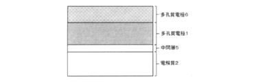
- FIG. 1 is a schematic cross-sectional view of a laminated structure of a laminated electrode, an intermediate layer, and an electrolyte according to an embodiment.
- FIG. 1 is a schematic cross-sectional view of a solid oxide cell according to an embodiment.
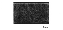
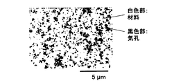
- 9 is a scanning electron microscope (SEM) image of a cross section of the electrode of Example 3. A binarized image (white part: material, black part: pores) obtained by image analysis of the cross section of the electrode of Example 3.
- the electrode resistance is the combined resistance of the reaction resistance and the gas diffusion resistance, but there is a trade-off between expanding the reaction field to reduce the reaction resistance and securing a gas diffusion path to reduce the gas diffusion resistance. For this reason, there has been a limit in reducing the electrode resistance. Therefore, the present inventors have proposed that the solid oxide cell electrode be a composite of a plurality of oxides or metal oxides at a specific content ratio to have a specific particle diameter, a specific film thickness, and a specific porosity. As a result, it has been found that the reaction resistance and the gas diffusion resistance can be reduced at the same time, and as a result, the electrode resistance can be dramatically reduced.
- an electrode for a solid oxide cell of the present invention a solid oxide cell using the same, and a method of manufacturing the same will be described based on embodiments and examples.
- FIG. 1 schematically shows a cross section of an electrode according to an embodiment of the present invention.
- the electrode of this embodiment is porous and has pores for gas diffusion (porous electrode 1).
- the porous electrode 1 includes an electron conductive material 3 and an ion conductive material 4.
- the porosity of the porous electrode is 1 to 30% by volume.
- the electron conductive material 3 is an electron conductive material for an air electrode, while when the electrode to be manufactured is a fuel electrode, the electron conductive material 3 is , An electron conductive material for fuel electrodes.
- the porous electrode 1 is formed on an electrolyte 2 which is an ion conductive material.
- the electrolyte 2 has a dense body layer for preventing gas cross leak.
- the entire electrolyte 2 may be a dense body.
- the relative density of the dense body layer of the electrolyte 2 is 90 to 100% by volume, more preferably 97 to 100% by volume, and particularly preferably 98 to 100% by volume. This is because the gas cross leak prevention function can be further improved.
- the thickness of the dense body layer of the electrolyte 2 is 0.1 ⁇ m to 1 mm, more preferably 0.5 ⁇ m to 100 ⁇ m, and particularly preferably 1 ⁇ m to 30 ⁇ m.
- the resistance of the dense body layer of the electrolyte 2 can be reduced while maintaining the gas cross leak prevention function.
- FIG. 2 schematically shows a cross-sectional view of the electrode according to the embodiment of the present invention.
- an intermediate layer 5 having a reaction preventing function is used between the porous electrode 1 and the electrolyte 2, and the porous electrode 1 is placed on the intermediate layer 5.
- the intermediate layer 5 is an ion conductive material.
- a porous electrode 6 having a higher porosity than the porous electrode 1 is formed on the porous electrode 1 in order to improve the gas diffusion property and the electrical current collecting property. I do.
- the porous electrode 1 can be formed as a specialized electrode (referred to as a functional layer, a catalyst layer, or an active layer) for reducing the electrode resistance.
- the electron conductive material for the air electrode refers to a material that can be used in a high-temperature oxidizing atmosphere, has catalytic activity for the oxidation or reduction reaction of the air electrode side gas, and has a property of conducting electrons.
- the electron conductive material for the air electrode is not particularly limited, and examples thereof include oxides such as (LaSr) MnO 3 , (LaSr) FeO 3 , (LaSr) CoO 3 , and (LaSr) (CoFe) O 3.
- the electron conductive oxide for the air electrode may be a single type or a combination of two or more types.
- A includes one or more of Y, La, Ce, Pr, Sm, and Gd, and preferably includes one or more of La, Sm, and Gd.
- B contains at least one of Sr, Ca and Ba, and preferably contains Sr.
- C contains one or more of Cr, Mn, Fe, Co, Ni, and Cu, and preferably contains one or more of Mn, Fe, and Co.
- x is 0.20 to 0.60, preferably 0.25 to 0.50, particularly preferably 0.30 to 0.50.
- y is 0.95 to 1.15, preferably 1.00 to 1.10, particularly preferably 1.00 to 1.05.
- Z is -1.00 to 1.00, preferably -0.50 to 0.50, and particularly preferably -0.30 to 0.30.
- the perovskite-type oxide material represented by the general formula (1) may be used alone or in combination of two or more.
- the ion conductive material refers to a material having a property of conducting ions that are oxidized or reduced at the air electrode.
- the ion conductive material is not particularly limited.
- stabilized zirconia doped with a metal element such as Al, Ca, Sc, Y, and Ce; metals such as Sc, Y, La, Sm, Gd, and Yb Element-doped ceria; lanthanum gallate doped with a metal element such as Mg, Al, Ca, Sr, Cr, Mn, Fe, Co, Ni; Mg, Al, Ca, Sr, Cr, Mn, Fe , Lanthanum aluminate doped with a metal element such as Co, Ni; lanthanum scandinate doped with a metal element such as Mg, Al, Ca, Sr, Cr, Mn, Fe, Co, Ni; Y, Nb Oxide doped with a metal element such as, Gd, W: pyrochlore-type oxides such as lan
- stabilized zirconia, doped ceria, doped barium zirconate, and doped barium zirconate serate are preferable.
- An electron conductive material for an anode refers to a material that can be used in a high-temperature reducing atmosphere, has catalytic activity for oxidation or reduction of an anode electrode gas, and has a property of conducting electrons. Sometimes it contains oxides that are reduced to metals.
- the electron conductive material for the fuel electrode is not particularly limited, and examples thereof include oxides such as iron oxide, nickel oxide, and copper oxide.
- the electron conductive material for the fuel electrode may be a single type or a combination of two or more types.
- nickel oxide is preferable.
- the electrode of the present invention is a porous body in which an electron conductive material and an ion conductive material are combined.
- the mass ratio between the electron conductive material and the ion conductive material in the electrode is 75:25 to 25:75, preferably 70:30 to 30:70, and particularly preferably 60. : 40 to 40:60.
- the mass ratio between the electron conductive material and the ion conductive material in the electrode is within the above range, the number of contact points between the electron conductive material and the ion conductive material increases, so that the reaction field is expanded and the electrode resistance is increased. Lower.
- the average particle size of the primary particles in the electron conductive material and the ion conductive material in the electrode of the present invention is 1 nm to 1 ⁇ m, preferably 5 nm to 0.5 ⁇ m, particularly preferably 10 nm to 0.2 ⁇ m.
- the average particle diameter of the primary particles in the electron conductive material and the ion conductive material in the electrode is within the above range, the contact point between the electron conductive material and the ion conductive material increases, and the specific surface area in the electrode increases. The increase increases the reaction field and lowers the electrode resistance.
- the average particle size of the primary particles is calculated by X-ray diffraction (eg, SmartLab, manufactured by Rigaku Corporation) and Scherrer's formula (Scherrer constant: 0.9).
- the thickness of the electrode of the present invention is 0.5 ⁇ m to 50 ⁇ m, preferably 0.5 ⁇ m to 25 ⁇ m, particularly preferably 0.5 ⁇ m to 5 ⁇ m.
- the thickness of the electrode is within the above range, the gas diffusion resistance is reduced, so that the electrode resistance is reduced.
- the porosity of the electrode of the present invention is 1 to 30% by volume, preferably 2 to 25% by volume, particularly preferably 3 to 20% by volume.
- the porosity of the electrode is in the above range, the occupancy of the electron conductive material and the ion conductive material in the electrode per space is increased, and the reaction field is expanded, so that the electrode resistance is reduced.
- the electrode resistance is further reduced.
- the porosity of the electrode is 1 to 15% by volume, preferably 2 to 13% by volume, and particularly preferably 3 to 10% by volume.
- the porosity of the electrode is 5 to 20% by volume, preferably 7 to 18% by volume, particularly preferably 10 to 15% by volume.
- the porosity of the electrode is 7 to 25% by volume, preferably 8 to 20% by volume, and particularly preferably 12 to 18% by volume.
- the porosity of the electrode is 10 to 30% by volume, preferably 12 to 25% by volume, particularly preferably 15 to 20% by volume.
- the electrode of the present embodiment is suitably manufactured by the following manufacturing method.
- the electrode of the present invention that is, the porous electrode 1 is formed on the electrolyte 2 or the intermediate layer 5.
- the electrolyte 2 is generally a dense body to prevent gas leakage.
- the intermediate layer 5 may be either a dense body or a porous body, but preferably has a high relative density in order to enhance the reaction prevention function. Specifically, it is preferably from 60 to 100% by volume, more preferably from 70 to 100% by volume, and particularly preferably from 80 to 100% by volume.
- an oxide powder material is used as a raw material of the porous electrode 1.
- the average particle size of the primary particles when the electrode is formed can be controlled by the particle size of the oxide powder material, the dispersion state, the firing temperature, or the combination of the materials to be composited.
- the amount of the binder, the plasticizer, or the dispersant or the sintering temperature is changed, or carbon, cellulose, or a polymer-based pore-forming agent is additionally mixed to form the porous electrode.
- the porosity of 1 can be controlled.
- the method for producing the porous electrode 1 includes, for example, a step of applying a first slurry on a porous support, and then baking it at a first temperature to form an electrolyte 2, and a step of applying a second slurry on the electrolyte 2.
- the intermediate layer 5 for example, a step of applying the first slurry on a porous support and then firing at a first temperature to form the electrolyte 2
- the first slurry coating method includes a screen printing method, a spray coating method, a transfer method, a dip coating method, and the like.
- a coating film having a high molding density can be obtained by optimizing the particle dispersibility of the electrolyte material in the first slurry.
- the sintering of the coating film proceeds by firing at the first temperature.
- the thickness of the electrolyte 2 obtained after firing is preferably 0.5 to 30 ⁇ m.
- the electrolyte 2 In order to reduce the electric resistance, it is preferable to make the electrolyte 2 as thin as possible. On the other hand, extremely thinning causes gas leakage due to defects in the electrolyte 2. Therefore, it is appropriate that the electrolyte 2 has a film thickness of 0.5 ⁇ m or more to prevent defects, and a film thickness of 30 ⁇ m or less that allows the electric resistance of the electrolyte 2 to be ⁇ or less of the total electric resistance of the solid oxide cell.
- the firing temperature of this coating film is preferably 1250 to 1500 ° C, more preferably 1300 to 1450 ° C, and particularly preferably 1350 to 1400 ° C. This is because the sintering of the coating film proceeds sufficiently at a firing temperature of 1250 ° C. or more, and a dense electrolyte is obtained. Further, at a firing temperature of 1500 ° C. or less, diffusion of elements and volatilization of elements constituting the electrolyte 2 are suppressed.
- the firing time of the coating film is preferably 1 to 8 hours, more preferably 2 to 6 hours, and particularly preferably 3 to 4 hours.
- Examples of the method for applying the second slurry include a screen printing method, a spray coating method, a transfer method, and a dip coating method.
- the sintering of this coating film proceeds by firing at the third temperature.
- the thickness of the porous electrode 1 obtained after firing is preferably 0.5 to 50 ⁇ m.
- the porous electrode 1 preferably contains a perovskite oxide material as an electron conductive material.
- the porous electrode 1 is a material in which an electron conductive material and an ion conductive material are combined.
- the second temperature, which is the firing temperature of the porous electrode 1 is preferably from 700 to 1200 ° C, more preferably from 800 to 1100 ° C, and particularly preferably from 850 to 1050 ° C.
- the firing time is preferably 0.5 to 8 hours, more preferably 1 to 6 hours, and particularly preferably 1 to 3 hours.
- the third slurry coating method includes a screen printing method, a spray coating method, a transfer method, a dip coating method, and the like.
- a coating film having a high molding density can be obtained by optimizing the particle dispersibility of the intermediate layer material in the third slurry.
- the sintering of the coating film proceeds by firing at the third temperature, and the thickness of the intermediate layer 5 obtained after firing is desirably 0.1 to 15 ⁇ m.
- the thickness of the intermediate layer 5 is 0.1 ⁇ m or more in order to maintain the reaction preventing function, and the thickness of the intermediate layer 5 is 15 ⁇ m or less that can reduce the electric resistance of the intermediate layer 5 to 1 / or less of the total electric resistance of the solid oxide cell. Is appropriate.
- the firing temperature of the coating film is preferably from 1000 to 1400 ° C, more preferably from 1100 to 1350 ° C, and particularly preferably from 1150 to 1300 ° C. This is because a good sintering state can be obtained, and the influence of mutual diffusion of elements with the electrolyte 2 can be suppressed.
- the firing time of the coating film is preferably 0.5 to 4 hours, more preferably 1 to 3 hours, and particularly preferably 1 to 2 hours.
- FIGS. 3A and 3B schematically show cross-sectional views of the solid oxide cell according to the embodiment of the present invention.
- the solid oxide cell according to the embodiment of the present invention includes the porous electrode 7, the electrolyte 2, and the porous electrode 1 of the present invention. Further, an intermediate layer 5 as a reaction preventing intermediate layer and a porous electrode 6 for improving gas diffusibility and electric current collecting performance may be provided.
- the porous electrode 1 is an air electrode
- the first slurry is applied on the porous electrode 7 that is a fuel electrode, and then the first temperature is changed to the first temperature. And forming a porous electrode 1 by applying a second slurry on the electrolyte 2 and then firing at a second temperature.
- the intermediate layer 5 for example, a step of applying the first slurry on the porous electrode 1 and then baking it at the first temperature to form the electrolyte 2, and a step of applying the third slurry on the electrolyte 2 And then baking at a third temperature to form an intermediate layer 5, and applying a second slurry onto the intermediate layer 5 and then baking at a second temperature to form the porous electrode 1. It has a process.
- the porous electrode 7 is formed on the support 8, and the electrolyte 2 is formed on the porous electrode 7.
- the intermediate layer 5, the porous electrode 1, and, if necessary, the porous electrode 6 may be sequentially formed to produce a solid oxide cell.
- the air electrode may be either the porous electrode 1 or the porous electrode 7, and the fuel electrode may be an electrode that is not the air electrode.
- the porous electrode 1 is described as an air electrode.
- the support 8 used in the step of forming the electrolyte 2 is preferably a porous body. This is because good gas diffusivity can be realized.
- the porosity of the porous support 8 is, for example, 10 to 60% by volume.
- uniaxial pressure molding, injection molding, extrusion molding, cast molding, or the like can be employed, but is not particularly limited.
- the shape of the porous support 8 may be a flat plate shape or a tube shape, but is not particularly limited. Examples of the material of the support 8 include oxides such as alumina and zirconia, and heat-resistant metals.
- a first slurry as an electrolyte material is applied on the fuel electrode, and the fuel electrode and the applied material are co-sintered at a first temperature to obtain a thin-film dense electrolyte layer. That is, a laminate including the electrolyte 2 that is a thin-film dense electrolyte layer and the porous electrode 7 that is a fuel electrode formed on one surface of the electrolyte 2 is obtained. By co-sintering the fuel electrode and the coating material, the electrolyte can be shrunk together with the fuel electrode, and a dense electrolyte layer having a high relative density can be obtained.
- the method for applying the first slurry and the film thickness of the electrolyte 2 are the same as the method for applying the first slurry and the film thickness of the electrolyte 2 in the electrode manufacturing method.
- the preferred range of the first temperature, which is the co-sintering temperature of the fuel electrode and the electrolyte 2, and the reason therefor are the same as the preferred range of the firing temperature of the coating film, which is the material of the electrolyte 2, in the electrode manufacturing method and the reason therefor. is there.
- the preferable range of the co-sintering time and the reason therefor are the same as the preferable range of the firing time of the coating film which is the material of the electrolyte 2 in the electrode manufacturing method and the reason therefor.
- a third slurry as an intermediate layer material is applied on the electrolyte 2 and the applied material is sintered at a third temperature to obtain a thin film intermediate layer. That is, a laminate including the intermediate layer 5 as a thin film intermediate layer and the porous electrode 7 as a fuel electrode formed on one surface of the electrolyte 2 is obtained.
- the method of applying the third slurry and the thickness of the intermediate layer 5 are the same as the method of applying the third slurry and the film thickness of the intermediate layer 5 in the electrode manufacturing method.
- the preferable range of the third temperature, which is the firing temperature of the intermediate layer 5, and the reason therefor are the same as the preferable range of the firing temperature of the coating film, which is the material of the intermediate layer 5, in the method for manufacturing an electrode, and the reason therefor.
- the preferable range of the baking time and the reason therefor are the same as the preferable range of the baking time of the coating film, which is the material of the intermediate layer 5 in the method for manufacturing an electrode, and its reason.
- the porous electrode 1 as an air electrode is formed on the electrolyte 2 or the intermediate layer 5.
- the oxide contained in the porous electrode 1 and the second temperature that is the firing temperature of the porous electrode 1 are the same as in the method for manufacturing the electrode.
- a porous electrode 6 having a higher porosity than the porous electrode 1 may be formed on the porous electrode 1 in order to improve the gas diffusion property and the electrical current collecting property.
- the material and porosity of the porous electrode 6 are different from those of the porous electrode 1, but the manufacturing method is the same as that of the porous electrode 1.
- an electrolyte 2 In the solid oxide cell, an electrolyte 2, an intermediate layer 5 (if necessary), a porous electrode 1, and a porous electrode 6 (if necessary) are formed on a porous electrode 7 as a support.
- This porous electrode 1 is a product of the present invention.
- Air electrodes having different ratios of the electron conductive material and the ion conductive material, the average particle diameter of the primary particles, the film thickness, and the porosity were prepared according to the following procedures.
- the oxide powder material used as the raw material of the air electrode was produced by a spray pyrolysis method.
- the spray pyrolysis method is one of the techniques that can synthesize a nano-sized oxide powder material. Although a single oxide powder material can be synthesized, an oxide powder material in which two or more oxides are compounded can also be synthesized. At this time, a good dispersion state can be obtained in the two or more kinds of composite oxides. Another feature is that the primary particle size can be controlled in a wide range.
- the synthesis of the oxide powder material by the spray pyrolysis method in Examples will be described.
- an aqueous solution for spraying containing a metal salt of an electron conductive material source for an air electrode and a metal salt of an ion conductive material source is prepared, and the aqueous solution for spraying is atomized by ultrasonic vibration. Then, the atomized aqueous solution for spraying is introduced into a heating furnace to obtain an oxide powder material for an air electrode.
- the composition ratio of various metal elements constituting the primary particles of the electron conductive material for the air electrode and the primary particles of the ion conductive material was adjusted.
- the aqueous solution for atomization in the atomizer is atomized by ultrasonic vibration (1.75 MHz), and then the atomized aqueous solution for atomization is caused to flow by the air of a carrier gas through a pipe connected to the atomizer.
- the metal salt of the electron conductive material source for the air electrode and the metal salt of the ion conductive material source in the aqueous solution for spraying were thermally decomposed and oxidized to obtain an oxide powder material for the air electrode.
- a four-stage electric furnace (with a furnace temperature of 300, 500, 700, and 900 ° C.
- Spray aqueous solution s1 18.98 g of samarium nitrate hexahydrate, 8.01 g of strontium nitrate, 22.02 g of cobalt nitrate hexahydrate, and 8.45 g of cerium nitrate hexahydrate are weighed, dissolved in pure water, and then dissolved in pure water. Was adjusted to 1000 ml to prepare an aqueous solution s1 for spraying.
- the spray aqueous solution s1 is pyrolyzed by spraying to obtain 0.1 mol per liter of 80 parts by mass Sm 0.5 Sr 0.5 Co 3 (hereinafter, SSC) -20 parts by mass Ce 0.8 Sm 0.2 O 1.9 (hereinafter, SDC) can be synthesized.
- Aqueous solution for spraying s2 17.49 g of samarium nitrate hexahydrate, 6.82 g of strontium nitrate, 18.76 g of cobalt nitrate hexahydrate and 12.34 g of cerium nitrate hexahydrate are weighed, and otherwise the same method as in the aqueous solution for spraying s1 Thus, an aqueous solution s2 for spraying was prepared.
- 70 parts by mass of SSC-30 parts by mass of SDC at 0.1 mol per liter can be synthesized.
- Aqueous solution for spraying s3 16.07 g of samarium nitrate hexahydrate, 5.70 g of strontium nitrate, 15.67 g of cobalt nitrate hexahydrate, and 16.04 g of cerium nitrate hexahydrate were weighed, and otherwise the same as the aqueous solution for spraying s1
- An aqueous solution s3 for spraying was prepared by the method.
- 60 parts by mass SSC-40 parts by mass SDC of 0.1 mol per liter can be synthesized.
- Aqueous solution for spraying s4 14.72 g of samarium nitrate hexahydrate, 4.63 g of strontium nitrate, 12.73 g of cobalt nitrate hexahydrate and 19.54 g of cerium nitrate hexahydrate were weighed, and otherwise the same as the aqueous solution s1 for spraying An aqueous solution s4 for spraying was prepared by the method. By spray pyrolysis of the aqueous solution for spray s4, 50 parts by mass SSC-50 parts by mass SDC of 0.1 mol per liter can be synthesized.
- Spray aqueous solution s5 13.44 g of samarium nitrate hexahydrate, 3.61 g of strontium nitrate, 9.94 g of cobalt nitrate hexahydrate, and 22.88 g of cerium nitrate hexahydrate were weighed, and otherwise the same as the aqueous solution for spraying s1
- An aqueous solution s5 for spraying was prepared by the method.
- 0.1 mol per 1 L of 40 parts by mass SSC-60 parts by mass SDC can be synthesized.
- Spray aqueous solution s6 12.22 g of samarium nitrate hexahydrate, 2.64 g of strontium nitrate, 7.27 g of cobalt nitrate hexahydrate and 26.06 g of cerium nitrate hexahydrate were weighed, and otherwise the same as the aqueous solution for spraying s1
- An aqueous solution s6 for spraying was prepared by the method.
- 30 parts by mass SSC-70 parts by mass SDC of 0.1 mol per liter can be synthesized.
- Spray aqueous solution s7 11.06 g of samarium nitrate hexahydrate, 1.72 g of strontium nitrate, 4.74 g of cobalt nitrate hexahydrate, and 29.08 g of cerium nitrate hexahydrate were weighed, and otherwise the same as the aqueous solution s1 for spraying An aqueous solution s7 for spraying was prepared by the method. By subjecting the aqueous solution for spray s7 to spray pyrolysis, 20 parts by mass SSC-80 parts by mass SDC of 0.1 mol per liter can be synthesized.
- Aqueous solution for spraying s8 14.93 g of gadolinium nitrate hexahydrate, 4.61 g of strontium nitrate, 12.68 g of cobalt nitrate hexahydrate, and 19.61 g of cerium nitrate hexahydrate were weighed, and otherwise the same as the aqueous solution s1 for spraying An aqueous solution s8 for spraying was prepared by the method.
- the spray aqueous solution s8 Is spray-pyrolyzed to give 50 parts by mass of Gd 0.5 Sr 0.5 Co 3 (hereinafter referred to as GSC) -50 parts by mass of Ce 0.8 Gd 0.2 O 1.9 (hereinafter referred to as 0.1 mol / L). , GDC).
- Aqueous solution for spraying s9 11.43 g of lanthanum nitrate hexahydrate, 3.73 g of strontium nitrate, 12.63 g of manganese nitrate hexahydrate, 19.45 g of cerium nitrate hexahydrate and 5.05 g of gadolinium nitrate hexahydrate were weighed, Except for this, an aqueous solution for spraying s9 was prepared in the same manner as for the aqueous solution for spraying s1.
- aqueous solution s9 for spraying By subjecting the aqueous solution s9 for spraying to spray pyrolysis, 50 parts by mass of La 0.6 Sr 0.4 MnO 3 (hereinafter, LSM) -50 parts by mass of GDC can be synthesized at 0.1 mol per liter.
- LSM La 0.6 Sr 0.4 MnO 3
- GDC Gel Chemical Vapor Deposition
- Spray aqueous solution s10 25.98 g of lanthanum nitrate hexahydrate, 8.47 g of strontium nitrate, 5.82 g of cobalt nitrate hexahydrate, and 32.32 g of iron nitrate nonahydrate were weighed, and otherwise the same as the aqueous solution s1 for spraying
- An aqueous solution s10 for spraying was prepared by the method.
- La 0.6 Sr of 0.1mol per 1L 0.4 Co 0.2 Fe 0.8 O 3 hereinafter, LSCF
- oxide powder material p1 Using the spray aqueous solution s1, spray pyrolysis was performed by an ultrasonic spray pyrolysis method to obtain an oxide powder material p1 of SSC-SDC.
- oxide powder material p2 Using the sprayed aqueous solution s2, an SSC-SDC oxide powder material p2 was obtained in the same manner as the oxide powder material p1.
- oxide powder material p3 Using the spray aqueous solution s3, an SSC-SDC oxide powder material p3 was obtained in the same manner as the oxide powder material p1.
- oxide powder material p4 An oxide powder material p4 of SSC-SDC was obtained in the same manner as for the oxide powder material p1, using the spray aqueous solution s4. (5) oxide powder material p5 Using the spray aqueous solution s5, an SSC-SDC oxide powder material p5 was obtained in the same manner as the oxide powder material p1. (6) oxide powder material p6 Using the spray aqueous solution s6, an oxide powder material p6 of SSC-SDC was obtained in the same manner as for the oxide powder material p1. (7) oxide powder material p7 Using the spray aqueous solution s7, an SSC-SDC oxide powder material p7 was obtained in the same manner as for the oxide powder material p1.
- oxide powder material p8 GSC-GDC oxide powder material p8 was obtained in the same manner as for oxide powder material p1, using the spray aqueous solution s8.
- oxide powder material p9 Using the spray aqueous solution s9, an oxide powder material p9 of LSM-GDC was obtained in the same manner as for the oxide powder material p1.
- oxide powder material p10 An LSCF oxide powder material p10 was obtained in the same manner as for the oxide powder material p1, using the spray aqueous solution s10.
- ⁇ Preparation of electrode> A mixture of the above oxide powder material, ethyl cellulose, plasticizer, dispersant, and ⁇ -terpineol was kneaded in a kneader at room temperature for 1 minute and 30 seconds to obtain an electrode slurry. .
- the electrode slurry was formed on both surfaces of a CGO 90/10 sintered body pellet by a screen printing method.
- the CGO90 / 10 sintered body pellet was obtained by subjecting 2.2 g of CGO90 / 10 powder to uniaxial press molding at 20 MPa using a 26 mm diameter carbide die, followed by firing at 1350 ° C. for 3 hours.
- the electrode was obtained by firing under predetermined firing conditions.
- the control of the electrode film thickness was performed by changing the mesh thickness used for screen printing.
- the porosity was controlled by changing the mass of ethyl cellulose with respect to the mass of the oxide powder material.
- Example 1 The oxide powder material p2 was used. Ethyl cellulose was 1 part by mass with respect to 100 parts by mass of the oxide powder material.
- the electrode of Example 1 was obtained by forming on both surfaces of a CGO90 / 10 sintered body pellet by screen printing using a mesh for 20 ⁇ m, followed by firing at 950 ° C. for 1 hour to obtain an electrode of Example 1.
- Example 2 The oxide powder material p3 was used. Ethyl cellulose was 1 part by mass with respect to 100 parts by mass of the oxide powder material.
- the electrode of Example 3 was obtained by forming on both surfaces of the CGO 90/10 sintered pellet by screen printing with a mesh for 20 ⁇ m and then firing at 950 ° C.
- Example 3 The oxide powder material p4 was used. Ethyl cellulose was 1 part by mass with respect to 100 parts by mass of the oxide powder material. The electrode of Example 3 was obtained by forming on both surfaces of the CGO 90/10 sintered pellet by screen printing with a mesh for 20 ⁇ m and then firing at 950 ° C. for 1 hour to obtain an electrode of Example 3.
- Example 4 The oxide powder material p5 was used. Ethyl cellulose was 1 part by mass with respect to 100 parts by mass of the oxide powder material. The electrode of Example 4 was obtained by forming both surfaces on the CGO 90/10 sintered pellets by screen printing using a mesh for 20 ⁇ m and firing at 950 ° C. for 1 hour.
- Example 5 The oxide powder material p6 was used. Ethyl cellulose was 1 part by mass with respect to 100 parts by mass of the oxide powder material. The electrode of Example 5 was obtained by forming on both surfaces of the CGO 90/10 sintered pellet by screen printing using a mesh for 20 ⁇ m, followed by firing at 950 ° C. for 1 hour to obtain an electrode of Example 5. (6) Example 6 The oxide powder material p4 was used. Ethyl cellulose was 1 part by mass with respect to 100 parts by mass of the oxide powder material. The electrode of Example 6 was obtained by forming on both sides of the CGO 90/10 sintered pellet by screen printing using a mesh for 3 ⁇ m and firing at 950 ° C. for 1 hour to obtain an electrode of Example 6.
- Example 7 The oxide powder material p8 was used. Ethyl cellulose was 1 part by mass with respect to 100 parts by mass of the oxide powder material. The electrode of Example 7 was obtained by forming on both surfaces of the CGO 90/10 sintered pellet by screen printing using a mesh for 20 ⁇ m, followed by firing at 950 ° C. for 1 hour to obtain an electrode of Example 7. (8) Example 8 The oxide powder material p9 was used. Ethyl cellulose was 1 part by mass with respect to 100 parts by mass of the oxide powder material. The electrode of Example 8 was obtained by forming on both surfaces of the CGO90 / 10 sintered pellet by screen printing using a mesh for 20 ⁇ m, and then firing at 1150 ° C. for 1 hour to obtain an electrode of Example 8.
- Embodiment 9 An oxide powder material in which the oxide powder material p10 and CGO 90/10 were mixed at a mass ratio of 50:50 was used. Ethyl cellulose was 1 part by mass with respect to 100 parts by mass of the mixed oxide powder material.
- the electrode of Example 9 was obtained by forming on both surfaces of the CGO 90/10 sintered pellets by screen printing using a mesh for 20 ⁇ m and firing at 950 ° C. for 1 hour to obtain an electrode of Example 9. (10)
- Example 10 An oxide powder material in which the oxide powder material p10 and CGO 90/10 were mixed at a mass ratio of 50:50 was used.
- Example 10 100 parts by mass of the mixed oxide powder material was molded on both surfaces of a CGO 90/10 sintered pellet by screen printing using a 3 ⁇ m mesh with ethyl cellulose as 1 part by mass, and then fired at 950 ° C. for 1 hour. Thus, an electrode of Example 10 was obtained.
- Embodiment 11 The oxide powder material p4 was used. Ethyl cellulose was used in an amount of 3 parts by mass based on 100 parts by mass of the oxide powder material.
- the electrode of Example 11 was obtained by forming both surfaces on the CGO 90/10 sintered pellets by screen printing using a mesh for 40 ⁇ m, followed by firing at 950 ° C. for 1 hour to obtain an electrode of Example 11.
- Example 12 The oxide powder material p4 was used.
- Ethyl cellulose was 1 part by mass with respect to 100 parts by mass of the oxide powder material.
- the electrodes of Example 12 were obtained by forming both surfaces on the CGO 90/10 sintered pellets by screen printing using a mesh for 10 ⁇ m and then firing at 950 ° C. for 1 hour.
- Comparative Example 1 The oxide powder material p1 was used. Ethyl cellulose was 1 part by mass with respect to 100 parts by mass of the oxide powder material.
- the electrode of Comparative Example 1 was obtained by forming on both surfaces of the CGO 90/10 sintered pellet by screen printing with a mesh for 20 ⁇ m and firing at 950 ° C. for 1 hour.
- Comparative example 2 The oxide powder material p7 was used. Ethyl cellulose was 1 part by mass with respect to 100 parts by mass of the oxide powder material.
- the electrode of Comparative Example 2 was obtained by forming both surfaces on the CGO 90/10 sintered pellets by screen printing using a mesh for 20 ⁇ m, followed by firing at 950 ° C. for 1 hour.
- Comparative example 3 The oxide powder material p4 was used. Ethyl cellulose was used in an amount of 8 parts by mass based on 100 parts by mass of the oxide powder material.
- the electrode of Comparative Example 3 was obtained by forming on both surfaces of a CGO 90/10 sintered pellet by screen printing using a mesh for 20 ⁇ m and firing at 950 ° C. for 1 hour.
- Comparative example 4 The oxide powder material p4 was used. Ethyl cellulose was 1 part by mass with respect to 100 parts by mass of the oxide powder material.
- An electrode of Comparative Example 4 was obtained by forming both surfaces on the CGO 90/10 sintered pellet by screen printing using a mesh for 60 ⁇ m and then firing at 950 ° C. for 1 hour.
- Comparative example 5 The oxide powder material p4 was used. Ethyl cellulose was used in an amount of 5 parts by mass based on 100 parts by mass of the oxide powder material.
- the electrode of Comparative Example 5 was obtained by forming on both surfaces of the CGO 90/10 sintered pellet by screen printing with a mesh for 3 ⁇ m and firing at 950 ° C. for 1 hour.
- Comparative example 6 The oxide powder material p9 was used. Ethyl cellulose was used in an amount of 8 parts by mass based on 100 parts by mass of the oxide powder material.
- the electrode of Comparative Example 6 was obtained by forming on both surfaces of a CGO 90/10 sintered pellet by screen printing using a mesh for 20 ⁇ m and firing at 950 ° C. for 1 hour.
- Comparative example 7 An oxide powder material in which the oxide powder material p10 and CGO 90/10 were mixed at a mass ratio of 50:50 was used. Ethyl cellulose was adjusted to 8 parts by mass with respect to 100 parts by mass of the mixed oxide powder material. An electrode of Comparative Example 7 was obtained by forming both surfaces on a CGO 90/10 sintered pellet by screen printing using a mesh for 20 ⁇ m, followed by firing at 950 ° C. for 1 hour. (8) Comparative Example 8 The oxide powder material p4 was used. Ethyl cellulose was used in an amount of 3 parts by mass based on 100 parts by mass of the oxide powder material.
- An electrode of Comparative Example 8 was obtained by forming on both surfaces of the CGO 90/10 sintered pellet by screen printing using a mesh for 3 ⁇ m and firing at 950 ° C. for 1 hour.
- Comparative Example 9 The oxide powder material p4 was used. Ethyl cellulose was used in an amount of 5 parts by mass based on 100 parts by mass of the oxide powder material.
- An electrode of Comparative Example 9 was obtained by forming both surfaces on the CGO 90/10 sintered pellet by screen printing with a mesh for 10 ⁇ m and then firing at 950 ° C. for 1 hour.
- Comparative Example 10 The oxide powder material p4 was used. Ethyl cellulose was used in an amount of 10 parts by mass based on 100 parts by mass of the oxide powder material.
- An electrode of Comparative Example 10 was obtained by forming both surfaces on the CGO 90/10 sintered pellets by screen printing using a mesh for 40 ⁇ m, followed by firing at 950 ° C. for 1 hour. ⁇ Measurement of average particle diameter of primary particles>
- the average particle diameter of the primary particles of the electrodes of Examples 1 to 12 and Comparative Examples 1 to 10 was determined by the peak half width of X-ray diffraction (eg, SmartLab, manufactured by Rigaku) and the Scherrer equation (Scherrer constant: 0.9). I asked. Table 1 shows the results. ⁇ Measurement of electrode thickness> The film thicknesses of the electrodes of Examples 1 to 12 and Comparative Examples 1 to 10 were determined by observing the cross sections of the electrodes with a scanning electron microscope (SEM, JSM-5600, manufactured by JEOL Ltd.). Table 1 shows the results. Further, as an example, FIG. 4 shows an SEM image of the electrode portion of the third embodiment.
- Examples 1 to 12 and Comparative Examples 1 to 10 were smoothed with a cross section polisher (eg, Ar ion beam, IB-09020CP, manufactured by JEOL), and then SEM (JSM-5600, manufactured by JEOL) ), And the porosity of the electrode was obtained by image processing of the contrast of the SEM image. Table 1 shows the results. Further, as an example, FIG. 5 shows an image processing result of the third embodiment.
- a cross section polisher eg, Ar ion beam, IB-09020CP, manufactured by JEOL
- SEM JSM-5600, manufactured by JEOL
- the electrode resistance per unit area at 700 ° C. in an air atmosphere was measured by an AC impedance method (1287, 1255B, manufactured by Solartron). Table 1 shows the results. Note that the electrode resistance is a Cole-Cole plot of the cell to be measured obtained by the AC impedance method, that is, the real part resistance Z ′ ( ⁇ ) and the imaginary part resistance Z for each frequency when the frequency is changed. In a graph obtained by plotting “( ⁇ ) as the real part resistance value Z ′ on the horizontal axis and the imaginary part resistance value Z” on the vertical axis, the real part resistance value of two intercepts with the horizontal axis of the graph is obtained. Is the difference.
- SSC and GSC of the electron conductive materials are materials generally used in a temperature range around 700 ° C.
- LSCF which is an electron conductive material
- LSM as an electron conductive material is generally used in a relatively high temperature range of 800 ° C. or higher. Therefore, here, the comparisons in Examples 1 to 7 and Examples 11 and 12 using SSC and GSC, Comparative Examples 1 to 5 and Comparative Examples 8 to 10, and Examples 9 and 10 using LSCF, The comparison with Example 7 and the comparison between Example 8 using LSM and Comparative Example 6 will be described separately.
- Examples 1 to 7 and Examples 9 to 10 exhibited lower electrode resistances than Comparative Examples 1 to 5 and Comparative Examples 7 to 10.
- Example 8 showed a lower electrode resistance than Comparative Example 6 when LSM was used as the electron conductive material. This means that the mass ratio of the electron conductive material to the ion conductive material, the average particle diameter of the primary particles in each material of the electron conductive material and the ion conductive material, the thickness of the electrode, and the porosity of the electrode in a specific range.
- the reaction resistance reduction effect by expanding the reaction field in the electrode and the gas diffusion resistance reduction effect by good gas diffusivity can be obtained at the same time, and a low electrode resistance is realized. .
Landscapes
- Chemical & Material Sciences (AREA)
- Chemical Kinetics & Catalysis (AREA)
- Electrochemistry (AREA)
- General Chemical & Material Sciences (AREA)
- Life Sciences & Earth Sciences (AREA)
- Engineering & Computer Science (AREA)
- Manufacturing & Machinery (AREA)
- Sustainable Development (AREA)
- Sustainable Energy (AREA)
- Inert Electrodes (AREA)
- Fuel Cell (AREA)
Abstract
L'invention concerne une électrode pour piles à oxyde solide et une pile à oxyde solide, qui sont conçues de telle sorte que : un matériau conducteur d'électrons et un matériau conducteur d'ions sont contenus ; le rapport en masse du matériau conducteur d'électrons au matériau conducteur d'ions est de 75:25 à 25:75 ; les diamètres moyens des particules respectifs des particules primaires dans le matériau conducteur d'électrons et dans le matériau conducteur d'ions sont de 1 nm à 1 µm ; l'épaisseur de film de l'électrode est de 0,5 µm à 50 µm ; et la porosité de l'électrode est de 1 % en volume à 30 % en volume.
Priority Applications (1)
| Application Number | Priority Date | Filing Date | Title |
|---|---|---|---|
| JP2020527513A JP7055473B2 (ja) | 2018-06-27 | 2019-06-24 | 固体酸化物形セル用電極及びそれを用いた固体酸化物形セル |
Applications Claiming Priority (2)
| Application Number | Priority Date | Filing Date | Title |
|---|---|---|---|
| JP2018-122046 | 2018-06-27 | ||
| JP2018122046 | 2018-06-27 |
Publications (1)
| Publication Number | Publication Date |
|---|---|
| WO2020004333A1 true WO2020004333A1 (fr) | 2020-01-02 |
Family
ID=68985004
Family Applications (1)
| Application Number | Title | Priority Date | Filing Date |
|---|---|---|---|
| PCT/JP2019/024969 Ceased WO2020004333A1 (fr) | 2018-06-27 | 2019-06-24 | Électrode pour piles à oxyde solide et pile à oxyde solide l'utilisant |
Country Status (2)
| Country | Link |
|---|---|
| JP (1) | JP7055473B2 (fr) |
| WO (1) | WO2020004333A1 (fr) |
Cited By (2)
| Publication number | Priority date | Publication date | Assignee | Title |
|---|---|---|---|---|
| JP2022028167A (ja) * | 2020-08-03 | 2022-02-16 | 森村Sofcテクノロジー株式会社 | 電気化学反応単セル |
| JP2023006322A (ja) * | 2021-06-30 | 2023-01-18 | 国立研究開発法人産業技術総合研究所 | プロトン伝導セラミックセル用電極、その製造方法、及びそれを用いたプロトン伝導セラミックセル |
Citations (3)
| Publication number | Priority date | Publication date | Assignee | Title |
|---|---|---|---|---|
| JP2013175479A (ja) * | 2013-05-09 | 2013-09-05 | Toshiba Corp | 固体酸化物電気化学セルの燃料極及び固体酸化物電気化学セル |
| JP2015153467A (ja) * | 2014-02-10 | 2015-08-24 | 日産自動車株式会社 | 金属支持型固体酸化物形燃料電池 |
| JP2017123231A (ja) * | 2016-01-05 | 2017-07-13 | 株式会社日本触媒 | 固体酸化物形燃料電池用単セル及びその製造方法、並びに、固体酸化物形燃料電池用カソード及びその製造方法 |
Family Cites Families (1)
| Publication number | Priority date | Publication date | Assignee | Title |
|---|---|---|---|---|
| JP6662067B2 (ja) * | 2016-01-29 | 2020-03-11 | ブラザー工業株式会社 | シート搬送装置及び画像記録装置 |
-
2019
- 2019-06-24 JP JP2020527513A patent/JP7055473B2/ja active Active
- 2019-06-24 WO PCT/JP2019/024969 patent/WO2020004333A1/fr not_active Ceased
Patent Citations (3)
| Publication number | Priority date | Publication date | Assignee | Title |
|---|---|---|---|---|
| JP2013175479A (ja) * | 2013-05-09 | 2013-09-05 | Toshiba Corp | 固体酸化物電気化学セルの燃料極及び固体酸化物電気化学セル |
| JP2015153467A (ja) * | 2014-02-10 | 2015-08-24 | 日産自動車株式会社 | 金属支持型固体酸化物形燃料電池 |
| JP2017123231A (ja) * | 2016-01-05 | 2017-07-13 | 株式会社日本触媒 | 固体酸化物形燃料電池用単セル及びその製造方法、並びに、固体酸化物形燃料電池用カソード及びその製造方法 |
Cited By (4)
| Publication number | Priority date | Publication date | Assignee | Title |
|---|---|---|---|---|
| JP2022028167A (ja) * | 2020-08-03 | 2022-02-16 | 森村Sofcテクノロジー株式会社 | 電気化学反応単セル |
| JP7278241B2 (ja) | 2020-08-03 | 2023-05-19 | 森村Sofcテクノロジー株式会社 | 電気化学反応単セル |
| JP2023006322A (ja) * | 2021-06-30 | 2023-01-18 | 国立研究開発法人産業技術総合研究所 | プロトン伝導セラミックセル用電極、その製造方法、及びそれを用いたプロトン伝導セラミックセル |
| JP7749206B2 (ja) | 2021-06-30 | 2025-10-06 | 国立研究開発法人産業技術総合研究所 | プロトン伝導セラミックセル用電極、その製造方法、及びそれを用いたプロトン伝導セラミックセル |
Also Published As
| Publication number | Publication date |
|---|---|
| JPWO2020004333A1 (ja) | 2021-05-13 |
| JP7055473B2 (ja) | 2022-04-18 |
Similar Documents
| Publication | Publication Date | Title |
|---|---|---|
| EP3279987B1 (fr) | Conducteur protonique, couche d'électrolyte solide de pile à combustible, structure de cellule et pile à combustible dotée de ces derniers | |
| Dailly et al. | High performing BaCe0. 8Zr0. 1Y0. 1O3-δ-Sm0. 5Sr0. 5CoO3-δ based protonic ceramic fuel cell | |
| JP6783042B2 (ja) | セル構造体の製造方法 | |
| JP6658754B2 (ja) | 固体酸化物形燃料電池、および電解質層−アノード接合体の製造方法 | |
| WO2016080019A1 (fr) | Anode pour pile à combustible à oxyde solide et son procédé de fabrication, et procédé de fabrication d'ensemble couche d'électrolyte-électrodes pour pile à combustible | |
| CN101847725A (zh) | 一种a缺位型钙钛矿结构固体氧化物燃料电池阴极材料 | |
| EP3537524B1 (fr) | Poudre de particules composites, matériau d'électrode pour cellule à oxyde solide, et électrode pour cellule à oxyde solide fabriquee a partir de ce materiau | |
| WO2015102701A2 (fr) | Formation de piles à combustible à oxyde solide | |
| JP7055473B2 (ja) | 固体酸化物形セル用電極及びそれを用いた固体酸化物形セル | |
| JP2004265746A (ja) | 固体酸化物形燃料電池 | |
| JP6664132B2 (ja) | 多孔質構造体とその製造方法、及びそれを用いた電気化学セルとその製造方法 | |
| WO2021256221A1 (fr) | Structure de cellule conductrice de protons, conducteur de protons, dispositif électrochimique et procédé de production de conducteur de protons | |
| JP7510669B2 (ja) | 固体酸化物形セル用燃料極、積層構造体及びその製造方法、並びに固体酸化物形セル及びその製造方法 | |
| JP2005259518A (ja) | 電気化学セル用アセンブリおよび電気化学セル | |
| JP5116221B2 (ja) | 酸化銅粒子を含有する電極材料及びそれを用いた固体酸化物形燃料電池の燃料極の製造方法 | |
| JP2004303712A (ja) | 固体酸化物形燃料電池 | |
| JP7136185B2 (ja) | セル構造体 | |
| JP7749206B2 (ja) | プロトン伝導セラミックセル用電極、その製造方法、及びそれを用いたプロトン伝導セラミックセル | |
| JP2004303713A (ja) | 固体酸化物形燃料電池 | |
| JP7114555B2 (ja) | 水蒸気電解用電極 | |
| CN111819720B (zh) | 燃料电池用电解质层-阳极复合部件、电池结构体、燃料电池以及复合部件的制造方法 | |
| JP2025148692A (ja) | プロトン伝導セラミック燃料電池用電解質、プロトン伝導セラミック燃料電池及びプロトン伝導セラミック燃料電池の製造方法 | |
| JP2026022797A (ja) | プロトン伝導型固体酸化物形セル用の電解質及び燃料極の積層体の製造方法、並びにプロトン伝導型固体酸化物形セル用電解質及びそれを有するプロトン伝導型固体酸化物形セル | |
| JP2018142419A (ja) | 固体酸化物形燃料電池セル | |
| JP2025146326A (ja) | 酸化物プロトン伝導型燃料電池セル |
Legal Events
| Date | Code | Title | Description |
|---|---|---|---|
| 121 | Ep: the epo has been informed by wipo that ep was designated in this application |
Ref document number: 19827553 Country of ref document: EP Kind code of ref document: A1 |
|
| DPE1 | Request for preliminary examination filed after expiration of 19th month from priority date (pct application filed from 20040101) | ||
| ENP | Entry into the national phase |
Ref document number: 2020527513 Country of ref document: JP Kind code of ref document: A |
|
| NENP | Non-entry into the national phase |
Ref country code: DE |
|
| 122 | Ep: pct application non-entry in european phase |
Ref document number: 19827553 Country of ref document: EP Kind code of ref document: A1 |