WO2020004341A1 - 商品収納装置 - Google Patents
商品収納装置 Download PDFInfo
- Publication number
- WO2020004341A1 WO2020004341A1 PCT/JP2019/024983 JP2019024983W WO2020004341A1 WO 2020004341 A1 WO2020004341 A1 WO 2020004341A1 JP 2019024983 W JP2019024983 W JP 2019024983W WO 2020004341 A1 WO2020004341 A1 WO 2020004341A1
- Authority
- WO
- WIPO (PCT)
- Prior art keywords
- product
- storage
- temperature
- fan
- storage device
- Prior art date
- Legal status (The legal status is an assumption and is not a legal conclusion. Google has not performed a legal analysis and makes no representation as to the accuracy of the status listed.)
- Ceased
Links
Images


Classifications
-
- G—PHYSICS
- G07—CHECKING-DEVICES
- G07F—COIN-FREED OR LIKE APPARATUS
- G07F9/00—Details other than those peculiar to special kinds or types of apparatus
- G07F9/10—Casings or parts thereof, e.g. with means for heating or cooling
-
- G—PHYSICS
- G07—CHECKING-DEVICES
- G07F—COIN-FREED OR LIKE APPARATUS
- G07F9/00—Details other than those peculiar to special kinds or types of apparatus
- G07F9/10—Casings or parts thereof, e.g. with means for heating or cooling
- G07F9/105—Heating or cooling means, for temperature and humidity control, for the conditioning of articles and their storage
-
- F—MECHANICAL ENGINEERING; LIGHTING; HEATING; WEAPONS; BLASTING
- F25—REFRIGERATION OR COOLING; COMBINED HEATING AND REFRIGERATION SYSTEMS; HEAT PUMP SYSTEMS; MANUFACTURE OR STORAGE OF ICE; LIQUEFACTION SOLIDIFICATION OF GASES
- F25D—REFRIGERATORS; COLD ROOMS; ICE-BOXES; COOLING OR FREEZING APPARATUS NOT OTHERWISE PROVIDED FOR
- F25D11/00—Self-contained movable devices, e.g. domestic refrigerators
-
- F—MECHANICAL ENGINEERING; LIGHTING; HEATING; WEAPONS; BLASTING
- F25—REFRIGERATION OR COOLING; COMBINED HEATING AND REFRIGERATION SYSTEMS; HEAT PUMP SYSTEMS; MANUFACTURE OR STORAGE OF ICE; LIQUEFACTION SOLIDIFICATION OF GASES
- F25D—REFRIGERATORS; COLD ROOMS; ICE-BOXES; COOLING OR FREEZING APPARATUS NOT OTHERWISE PROVIDED FOR
- F25D17/00—Arrangements for circulating cooling fluids; Arrangements for circulating gas, e.g. air, within refrigerated spaces
- F25D17/04—Arrangements for circulating cooling fluids; Arrangements for circulating gas, e.g. air, within refrigerated spaces for circulating air, e.g. by convection
- F25D17/06—Arrangements for circulating cooling fluids; Arrangements for circulating gas, e.g. air, within refrigerated spaces for circulating air, e.g. by convection by forced circulation
- F25D17/067—Evaporator fan units
-
- F—MECHANICAL ENGINEERING; LIGHTING; HEATING; WEAPONS; BLASTING
- F25—REFRIGERATION OR COOLING; COMBINED HEATING AND REFRIGERATION SYSTEMS; HEAT PUMP SYSTEMS; MANUFACTURE OR STORAGE OF ICE; LIQUEFACTION SOLIDIFICATION OF GASES
- F25D—REFRIGERATORS; COLD ROOMS; ICE-BOXES; COOLING OR FREEZING APPARATUS NOT OTHERWISE PROVIDED FOR
- F25D17/00—Arrangements for circulating cooling fluids; Arrangements for circulating gas, e.g. air, within refrigerated spaces
- F25D17/04—Arrangements for circulating cooling fluids; Arrangements for circulating gas, e.g. air, within refrigerated spaces for circulating air, e.g. by convection
- F25D17/06—Arrangements for circulating cooling fluids; Arrangements for circulating gas, e.g. air, within refrigerated spaces for circulating air, e.g. by convection by forced circulation
- F25D17/08—Arrangements for circulating cooling fluids; Arrangements for circulating gas, e.g. air, within refrigerated spaces for circulating air, e.g. by convection by forced circulation using ducts
-
- F—MECHANICAL ENGINEERING; LIGHTING; HEATING; WEAPONS; BLASTING
- F25—REFRIGERATION OR COOLING; COMBINED HEATING AND REFRIGERATION SYSTEMS; HEAT PUMP SYSTEMS; MANUFACTURE OR STORAGE OF ICE; LIQUEFACTION SOLIDIFICATION OF GASES
- F25D—REFRIGERATORS; COLD ROOMS; ICE-BOXES; COOLING OR FREEZING APPARATUS NOT OTHERWISE PROVIDED FOR
- F25D29/00—Arrangement or mounting of control or safety devices
-
- F—MECHANICAL ENGINEERING; LIGHTING; HEATING; WEAPONS; BLASTING
- F25—REFRIGERATION OR COOLING; COMBINED HEATING AND REFRIGERATION SYSTEMS; HEAT PUMP SYSTEMS; MANUFACTURE OR STORAGE OF ICE; LIQUEFACTION SOLIDIFICATION OF GASES
- F25D—REFRIGERATORS; COLD ROOMS; ICE-BOXES; COOLING OR FREEZING APPARATUS NOT OTHERWISE PROVIDED FOR
- F25D31/00—Other cooling or freezing apparatus
- F25D31/006—Other cooling or freezing apparatus specially adapted for cooling receptacles, e.g. tanks
- F25D31/007—Bottles or cans
-
- G—PHYSICS
- G07—CHECKING-DEVICES
- G07F—COIN-FREED OR LIKE APPARATUS
- G07F11/00—Coin-freed apparatus for dispensing, or the like, discrete articles
- G07F11/02—Coin-freed apparatus for dispensing, or the like, discrete articles from non-movable magazines
- G07F11/04—Coin-freed apparatus for dispensing, or the like, discrete articles from non-movable magazines in which magazines the articles are stored one vertically above the other
- G07F11/10—Coin-freed apparatus for dispensing, or the like, discrete articles from non-movable magazines in which magazines the articles are stored one vertically above the other two or more magazines having a common delivery chute
-
- G—PHYSICS
- G07—CHECKING-DEVICES
- G07F—COIN-FREED OR LIKE APPARATUS
- G07F11/00—Coin-freed apparatus for dispensing, or the like, discrete articles
- G07F11/02—Coin-freed apparatus for dispensing, or the like, discrete articles from non-movable magazines
- G07F11/28—Coin-freed apparatus for dispensing, or the like, discrete articles from non-movable magazines in which the magazines are inclined
- G07F11/32—Coin-freed apparatus for dispensing, or the like, discrete articles from non-movable magazines in which the magazines are inclined two or magazines having a common delivery chute
-
- G—PHYSICS
- G07—CHECKING-DEVICES
- G07F—COIN-FREED OR LIKE APPARATUS
- G07F17/00—Coin-freed apparatus for hiring articles; Coin-freed facilities or services
- G07F17/0064—Coin-freed apparatus for hiring articles; Coin-freed facilities or services for processing of food articles
- G07F17/0071—Food articles which need to be processed for dispensing in a cold condition, e.g. ice and ice cream
-
- F—MECHANICAL ENGINEERING; LIGHTING; HEATING; WEAPONS; BLASTING
- F25—REFRIGERATION OR COOLING; COMBINED HEATING AND REFRIGERATION SYSTEMS; HEAT PUMP SYSTEMS; MANUFACTURE OR STORAGE OF ICE; LIQUEFACTION SOLIDIFICATION OF GASES
- F25D—REFRIGERATORS; COLD ROOMS; ICE-BOXES; COOLING OR FREEZING APPARATUS NOT OTHERWISE PROVIDED FOR
- F25D2331/00—Details or arrangements of other cooling or freezing apparatus not provided for in other groups of this subclass
- F25D2331/80—Type of cooled receptacles
- F25D2331/803—Bottles
-
- F—MECHANICAL ENGINEERING; LIGHTING; HEATING; WEAPONS; BLASTING
- F25—REFRIGERATION OR COOLING; COMBINED HEATING AND REFRIGERATION SYSTEMS; HEAT PUMP SYSTEMS; MANUFACTURE OR STORAGE OF ICE; LIQUEFACTION SOLIDIFICATION OF GASES
- F25D—REFRIGERATORS; COLD ROOMS; ICE-BOXES; COOLING OR FREEZING APPARATUS NOT OTHERWISE PROVIDED FOR
- F25D2331/00—Details or arrangements of other cooling or freezing apparatus not provided for in other groups of this subclass
- F25D2331/80—Type of cooled receptacles
- F25D2331/805—Cans
-
- F—MECHANICAL ENGINEERING; LIGHTING; HEATING; WEAPONS; BLASTING
- F25—REFRIGERATION OR COOLING; COMBINED HEATING AND REFRIGERATION SYSTEMS; HEAT PUMP SYSTEMS; MANUFACTURE OR STORAGE OF ICE; LIQUEFACTION SOLIDIFICATION OF GASES
- F25D—REFRIGERATORS; COLD ROOMS; ICE-BOXES; COOLING OR FREEZING APPARATUS NOT OTHERWISE PROVIDED FOR
- F25D31/00—Other cooling or freezing apparatus
- F25D31/005—Combined cooling and heating devices
Definitions
- the present invention relates to a product storage device, and more particularly to a product storage device for storing a product such as a beverage contained in a container such as a can or a plastic bottle.
- vending machines that sell products are known as product storage devices that store products such as beverages contained in containers such as cans and plastic bottles.
- a vending machine includes a main body cabinet that is a main body of the vending machine.
- the main body cabinet is formed as a rectangular heat-insulating housing having an open front surface.
- the main body cabinet has an outer door and an inner door on the front surface thereof, and a storage cabinet therein.
- the outer door is for opening and closing the front opening of the main body cabinet.
- the inner door has a heat insulating structure, and is used to open and close the front of the storage.
- the storage has a heat insulating structure, in which an evaporator, a fan in the storage, and a product rack are provided.
- the evaporator forms a refrigeration cycle with a compressor, a condenser, and the like provided outside the storage, and cools its surrounding air.
- the merchandise rack is a so-called serpentine-type merchandise rack in which a plurality of merchandise columns for storing inserted merchandise in a meandering shape along the vertical direction are provided along the front-rear direction.
- a sales command is given, the lowest product located at the lowermost position of the corresponding product column is paid out, and can be taken out through a product outlet provided in the outer door.
- the compressor and the fan in the refrigerator are driven to blow the air cooled by the evaporator, thereby cooling the atmosphere inside the storage. Thereby, the product stored in the product rack is cooled.
- a vending machine which performs a forced stop operation for forcibly stopping driving of a compressor and a fan in a refrigerator in a predetermined time zone ( For example, see Patent Document 1).
- a product rack called a so-called slant truck instead of the above-mentioned serpentine type product rack.
- a product rack a plurality of product columns are provided along the up-down direction, in which product columns for storing products are arranged in a row in a laterally inclined posture in a storage passage that is inclined and extended from the upstream side to the downstream side. It is configured. That is, in such a product rack, each product column is provided so that the most downstream products are arranged in the vertical direction.
- a product storage device is provided with a product column for storing products in a line, wherein a plurality of stages of heat insulation are provided so that the most downstream products are lined up and down.
- a product storage device comprising: a storage having a structure; and air blowing means for adjusting the internal atmosphere of the storage to a predetermined temperature by blowing air adjusted by temperature adjusting means provided in the storage. In the state where the temperature adjusting unit and the blowing unit are stopped, when the internal temperature of the storage is equal to or higher than a predetermined reference temperature, the blowing unit is turned on for a predetermined time. It is characterized by comprising control means for driving.
- the product column stores the products in a storage passage that is inclined and extended so as to be gradually lowered from the upstream side to the downstream side so as to line up in a sideways posture. It is characterized by.
- the present invention is also characterized in that, in the above-mentioned commodity storage device, the temperature adjusting means is provided at a lower portion of the storage and cools its surrounding air.
- the present invention is also characterized in that, in the above-mentioned commodity storage device, the air blowing means is installed in the lower part of the storage near the temperature adjusting means.
- the present invention is characterized in that, in the above-mentioned commodity storage device, the temperature adjusting means is a refrigerator and an evaporator.
- the blowing means is a fan in the refrigerator.
- the blowing unit when the temperature inside the storage is equal to or higher than a predetermined reference temperature in a state where the control unit stops driving the temperature adjusting unit and the blowing unit, the blowing unit is determined in advance. Since it is driven only for a time, the internal air on the lower side and the internal air on the upper side in the storage are sufficiently stirred, and the temperature can be made substantially uniform over the entire area of the storage. The ambient temperature of downstream commodities can also be substantially uniform. Therefore, there is an effect that the temperature variation of the most downstream products in each product column can be reduced while reducing the power consumption.
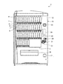
- FIG. 1 is a front view showing a configuration of a vending machine according to an embodiment of the present invention.
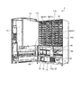
- FIG. 2 is a perspective view showing the internal structure of the vending machine shown in FIG.
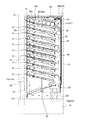
- FIG. 3 is a sectional side view showing the internal structure of the vending machine shown in FIG.
- FIG. 4 is a block diagram schematically showing a characteristic control system of the vending machine shown in FIG.
- FIG. 5 is a flowchart illustrating the processing content of the in-compartment fan control processing performed by the controller of the controller during the forced stop operation.
- the merchandise storage device will be described as a vending machine that sells merchandise to be stored.
- FIG. 1 is a front view showing a configuration of a vending machine according to an embodiment of the present invention.
- 2 and 3 show the internal structure of the vending machine shown in FIG. 1, respectively.
- FIG. 2 is a perspective view
- FIG. 3 is a sectional side view.
- FIG. 4 is a block diagram schematically showing a characteristic control system of the vending machine shown in FIG.
- the vending machine 1 illustrated here sells beverages contained in containers such as cans and plastic bottles as commodities, and has a front door 12 on the front of a main body cabinet 10 for accommodating commodities.
- the front door 12 is supported by the main body cabinet 10 via one side edge, and can open and close a front opening of the main body cabinet 10.
- the front door 12 is provided with an exhibition room 2.
- the exhibition room 2 is for displaying a plurality of product samples D therein, and has a rectangular shape with an open front.
- the exhibition room 2 is provided with a plurality of stages 5 (four in the example of FIG. 1) in the vertical direction, and each stage 5 has a plurality of (a total of 42 in the example of FIG. 1) product samples D. Are erected side by side.
- the front opening of the exhibition room 2 is covered with a transparent resin panel 4 so that intrusion of foreign matter from the outside is prevented, while the inside can be visually recognized through the resin panel 4.
- the resin panel 4 is provided with a selection button 7 corresponding to each of the product samples D. That is, four select buttons 6 are arranged in the vertical direction so as to correspond to the stage 5.
- a coin insertion slot 21, a bill insertion slot 22, a return lever 23, a pop-up handle 24, a display unit 25, and a non-contact card reader / writer 26 are arranged on the right side of the exhibition room 2 in the front door 12.
- a coin return slot 27 and a product outlet 28 are arranged below the box.
- the display unit 25 displays various types of information related to the purchase of goods such as inserted money.
- the contactless card reader / writer 26 reads or writes electronic money card information.
- the product outlet 28 is an opening for a user to take out purchased products.
- reference numeral 3 in FIG. 1 denotes an advertisement placement unit provided inside the exhibition room 2.
- a plurality (three in the illustrated example) of storages 11a, 11b, and 11c are provided in a side-by-side manner. These storages 11a, 11b, 11c are provided so as to face the front opening of the main body cabinet 10, and have a heat insulating structure in a room for storing products at a desired temperature.
- These storages 11a, 11b, 11c are opened and closed by a heat insulating door 13 whose front opening is swingably provided at one side edge of the main body cabinet 10.
- the heat-insulating door 13 is divided into upper and lower parts, and a lower door 13b has a product outlet 14 corresponding to each of the storages 11a, 11b, 11c, and a product outlet for opening and closing the product outlet 14.
- a door 15 is provided.
- the storages 11a, 11b, 11c are provided with a product rack 40, an evaporator 50, a fan 52 in the storage, and a cold storage material 54.
- the product rack 40 is configured by providing a plurality of (for example, 10) product shelves 41 in a plurality of stages in the vertical direction.
- Each of the product shelves 41 has a shelf plate 41a which is gradually inclined downward from the front to the rear, and a product column 42 is provided on an upper surface of the shelf plate 41a.
- the shelf guides 41b are erected on the upper surface of the shelf 41a, so that the product columns 42 are arranged side by side.
- Such a product column 42 has a storage passage 42a extending in the front-rear direction, and a product inserted from the input port 43 at the front end of the storage passage 42a is placed in a sideways posture along the storage passage 42a. They are stored in a line and are called slant columns.
- the extension length of the storage passage 42a is the same as the extension length of the storage passage 42a of the other product column 42, and the number of products that can be stored is the same as the other product columns 42.
- a plurality of product columns 42 for storing products in a line are provided so that the most downstream products are lined up and down.
- a payout mechanism 44 is provided at the rear end of the storage passage 42a.
- the dispensing mechanism 44 is the most rearwardly located product among the products stored in the storage passage 42a when driven individually or by applying a driving force of a motor (not shown) common to the other discharging mechanisms 44.
- the downstream products are paid out to the falling passage 45 on the rear side of the product rack 40.
- Reference numeral 46 in FIG. 3 denotes a brake plate provided at the rear end of each product shelf 41. The brake plate 46 is for dropping the commodity falling in the fall passage 45 while braking the commodity.
- the evaporator 50 is installed in the storage 11a, 11b, 11c below the unloading shooter 47.
- the evaporator 50 is a refrigerant circuit that circulates a refrigerant with a refrigerator 51 (see FIG. 4) installed in the machine room 16 that is inside the main body cabinet 10 and below the storages 11a, 11b, and 11c. It constitutes.
- the evaporator 50 causes heat exchange between the low-temperature and low-pressure refrigerant passing through the refrigerant flow path of the evaporator 50 and the ambient air. It cools down.
- a plurality of (in the case of the refrigerant in FIG. 3, two) internal fans 52 are provided, and have a lower fan 52a and an upper fan 52b.
- the lower fan 52a is installed on the front side of the evaporator 50.
- the upper fan 52b is installed at the upper end of the drop passage 45.
- the cold storage material 54 is installed above the storages 11a, 11b, 11c, that is, in front of the upper fan 52b.
- the cold storage material 54 is configured such that a cold storage agent such as water or a gelling agent is sealed in a container.
- the regenerative material 54 is cooled by the evaporator 50 by driving the in-compartment fan 52, and is cooled by the regenerative agent cooled by the air passing through the drop passage 45.
- the cold storage material 54 is installed in front of the upper fan 52b.
- the place where the cold storage material 54 is installed is not particularly limited, and the products stored in the product rack 40 are preferably used. What is necessary is just to be able to cool.
- the vending machine 1 includes a refrigerator 51, a heater 53, a dispensing mechanism 44, an in-compartment fan 52, a sold-out switch 48, a selection button group 6 including a selection button 7, a display unit 25,
- the card reader / writer 26, external communication processing unit 55, internal temperature sensor S, storage unit 56, remote controller 57, coin mechanism 58, and building validator 59 are connected to the controller 60.
- the refrigerator 51 forms a refrigerant circuit together with the above-described evaporator 50, and includes a compressor that sucks and compresses the refrigerant evaporated by the evaporator 50, and a condenser that condenses the refrigerant compressed by the compressor. have.
- the heater 53 is installed in the storages 11a and 11b other than the storage 11c on the right side.
- the heater 53 is a heating unit that is energized to heat ambient air when driven.
- the sold-out switch 48 is installed in each of the product columns 42, and detects a sold out in the installed product column 42.
- the external communication processing unit 55 performs a process of connecting to an external network (not shown) and a process of connecting to a short-range wireless communication such as WiFi (registered trademark).
- the in-compartment temperature sensor S is installed on the upper side of each of the accommodations 11a, 11b, 11c, and detects the in-compartment temperature, which is the internal temperature of the accommodations 11a, 11b, 11c.
- the inside temperature sensor S as described above gives the detected inside temperature to the controller 60 as a signal.
- the storage unit 56 stores and saves various information.
- the storage unit 56 stores reference temperature information 56a used in the in-compartment fan control process described later.
- the reference temperature information 56a includes reference information serving as a threshold value for starting driving of the internal fan 52 in the internal fan control process.
- the remote controller 57 is an input / output unit wired to the controller 60.
- the coin mechanism 58 is a coin processing device, and performs a deposit process and the like of coins inserted through the coin insertion slot 21.
- the coin mechanism 58 sends out the coin to the coin return slot 27 when there is change, and returns the coin deposited through the coin slot 21 when the return lever 23 is operated. It is sent to the mouth 27.
- the bill validator 59 is a bill processing device that performs a deposit process and the like of a bill inserted through the bill insertion slot 22.
- the controller 60 has a control unit 60a.
- the control unit 60a performs overall control of each connected unit.
- the vending machine 1 having the above-described configuration, by driving the refrigerator 51 and driving the internal fan 52 (the lower fan 52a and the upper fan 52b), as shown by the dashed arrow in FIG.
- the air inside the storages 11a, 11b, 11c can be circulated. That is, after the air cooled by the evaporator 50 passes through the drop passage 45 from below to above, and the air that has passed through the drop passage 45 passes forward through the upper portions of the storages 11a, 11b, and 11c, It passes downward and reaches the evaporator 50 again. In this way, by circulating the air inside the storages 11a, 11b, 11c, the products stored in the respective product columns 42 can be cooled to a predetermined temperature.
- the vending machine 1 when a predetermined cooling-in operation start time is reached, a cooling-in operation in which the number of revolutions of the internal fan 52 is increased to sufficiently cool the products in the product column 42 is performed, and thereafter, When a predetermined drive stop time is reached, a forced stop operation for stopping the driving of the refrigerator 51 and the in-compartment fan 52 is performed until a preset release time is reached.
- a predetermined drive stop time When a predetermined drive stop time is reached, a forced stop operation for stopping the driving of the refrigerator 51 and the in-compartment fan 52 is performed until a preset release time is reached.
- FIG. 5 is a flowchart showing the processing contents of the in-compartment fan control processing performed by the controller of the controller during the forced stop operation. In the following, description will be given for the right storage 11c.
- the control unit 60a of the controller 60 waits for an in-compartment temperature input from the in-compartment temperature sensor S (step S101).
- step S101 When there is an input of the refrigerator temperature (step S101: Yes), the control unit 60a reads the reference temperature information 56a from the storage unit 56, and determines whether the refrigerator temperature is equal to or higher than the reference temperature (step S101). S102).
- step S102 When the inside temperature is lower than the reference temperature (step S102: No), the control unit 60a determines that the inside temperature on the upper side of the storage case 11c has not risen so much, and executes the processing described later. The procedure is returned without performing the processing and the current processing is terminated.
- step S102 if the internal temperature is equal to or higher than the reference temperature (step S102: Yes), the control unit 60a sends a drive command to the lower fan 52a (step S103). This drives the lower fan 52a to circulate the air inside the storage 11c. As a result, the lower internal air and the upper internal air in the housing 11c are stirred.
- the control unit 60a that has driven the lower fan 52a in this way determines whether a predetermined time (for example, 30 minutes) has elapsed since the lower fan 52a was driven by the built-in timer unit (step S104). When it is determined that the predetermined time has elapsed (step S104: Yes), a drive stop command is given to the lower fan 52a (step S105), and thereafter, the procedure is returned, and the current process ends.
- a predetermined time for example, 30 minutes
- the internal air on the lower side and the internal air on the upper side in the housing 11c are sufficiently stirred, and the temperature can be made substantially uniform over the entire area of the housing 11c.
- the internal temperature sensor S When the detected inside temperature of the storages 11a, 11b, 11c is equal to or higher than a predetermined reference temperature, the lower fan 52a is driven for a predetermined time, so that it is substantially uniform over the entire area of the storages 11a, 11b, 11c. And the ambient temperature of the most downstream products in each product column 42 can be made substantially uniform. Therefore, it is possible to reduce the temperature variation of the products at the lowermost stream of each product column 42 while reducing the power consumption.
- the refrigerator 51 and the evaporator 50 have been described as the temperature adjusting means for adjusting the internal temperature of the storages 11a, 11b, 11c to a predetermined temperature. Adjustment means may be used.
- the lower fan 52a is driven in the in-compartment fan control process.
- the upper fan 52b may be driven, or the lower fan 52a may be driven.
- the upper fan 52b may be driven.
- the vending machine 1 is described as an example of the product storage device.
- the product storage device may be a showcase or the like.
Landscapes
- Engineering & Computer Science (AREA)
- Physics & Mathematics (AREA)
- General Physics & Mathematics (AREA)
- Chemical & Material Sciences (AREA)
- Combustion & Propulsion (AREA)
- Mechanical Engineering (AREA)
- Thermal Sciences (AREA)
- General Engineering & Computer Science (AREA)
- Life Sciences & Earth Sciences (AREA)
- Food Science & Technology (AREA)
- Control Of Vending Devices And Auxiliary Devices For Vending Devices (AREA)
- Devices That Are Associated With Refrigeration Equipment (AREA)
Abstract
Description
Claims (6)
- 商品を一列に並ぶ態様で収納する商品コラムが、それぞれの最下流の商品が上下方向に沿って並ぶよう複数段設けられた断熱構造の収容庫と、
前記収容庫に配設された温度調整手段により調整された空気を送風することにより、該収容庫の内部雰囲気を所定の温度に調整する送風手段と
を備えた商品収納装置であって、
前記温度調整手段及び前記送風手段を駆動停止にさせた状態で、前記収容庫の庫内温度が予め決められた基準温度以上となる場合、前記送風手段を予め決められた時間だけ駆動させる制御手段を備えたことを特徴とする商品収納装置。 - 前記商品コラムは、上流側から下流側に向けて漸次低くなる態様で傾斜延在した収納通路に、商品を横倒姿勢で一列に並ぶよう収納することを特徴とする請求項1に記載の商品収納装置。
- 前記温度調整手段は、前記収容庫の下部に設置され、自身の周囲空気を冷却することを特徴とする請求項1又は請求項2に記載の商品収納装置。
- 前記送風手段は、前記収容庫の下部において、前記温度調整手段の近傍に設置されたことを特徴とする請求項3に記載の商品収納装置。
- 前記温度調整手段は、冷凍機及び蒸発器であることを特徴とする請求項3に記載の商品収納装置。
- 前記送風手段は、庫内ファンであることを特徴とする請求項4に記載の商品収納装置。
Priority Applications (5)
| Application Number | Priority Date | Filing Date | Title |
|---|---|---|---|
| CN201980042689.5A CN112771586A (zh) | 2018-06-27 | 2019-06-24 | 商品收纳装置 |
| EP19824712.4A EP3816949A4 (en) | 2018-06-27 | 2019-06-24 | PRODUCT RECEPTION DEVICE |
| KR1020217001930A KR102704932B1 (ko) | 2018-06-27 | 2019-06-24 | 상품 수납 장치 |
| JP2020527520A JP7200244B2 (ja) | 2018-06-27 | 2019-06-24 | 商品収納装置 |
| US17/255,285 US11450168B2 (en) | 2018-06-27 | 2019-06-24 | Product accommodating device |
Applications Claiming Priority (2)
| Application Number | Priority Date | Filing Date | Title |
|---|---|---|---|
| JP2018121647 | 2018-06-27 | ||
| JP2018-121647 | 2018-06-27 |
Publications (1)
| Publication Number | Publication Date |
|---|---|
| WO2020004341A1 true WO2020004341A1 (ja) | 2020-01-02 |
Family
ID=68987085
Family Applications (1)
| Application Number | Title | Priority Date | Filing Date |
|---|---|---|---|
| PCT/JP2019/024983 Ceased WO2020004341A1 (ja) | 2018-06-27 | 2019-06-24 | 商品収納装置 |
Country Status (6)
| Country | Link |
|---|---|
| US (1) | US11450168B2 (ja) |
| EP (1) | EP3816949A4 (ja) |
| JP (1) | JP7200244B2 (ja) |
| KR (1) | KR102704932B1 (ja) |
| CN (1) | CN112771586A (ja) |
| WO (1) | WO2020004341A1 (ja) |
Families Citing this family (2)
| Publication number | Priority date | Publication date | Assignee | Title |
|---|---|---|---|---|
| CN113487797A (zh) * | 2021-07-05 | 2021-10-08 | 立讯精密工业股份有限公司 | 无人销售装置和销售方法 |
| JP7729165B2 (ja) * | 2021-10-15 | 2025-08-26 | 富士電機株式会社 | 自動販売機 |
Citations (4)
| Publication number | Priority date | Publication date | Assignee | Title |
|---|---|---|---|---|
| JPH04267498A (ja) | 1991-02-21 | 1992-09-24 | Fuji Electric Co Ltd | 自動販売機の冷却・加熱制御装置 |
| JPH0676153A (ja) * | 1992-08-28 | 1994-03-18 | Toshiba Corp | 自動販売機 |
| JP2007286999A (ja) * | 2006-04-19 | 2007-11-01 | Matsushita Electric Ind Co Ltd | 自動販売機 |
| JP2010055172A (ja) * | 2008-08-26 | 2010-03-11 | Fuji Electric Retail Systems Co Ltd | 自動販売機 |
Family Cites Families (11)
| Publication number | Priority date | Publication date | Assignee | Title |
|---|---|---|---|---|
| US5080256A (en) * | 1990-01-18 | 1992-01-14 | Rock-Ola Manufacturing Corporation | Slant shelf magazine for automatic vending machines |
| TW446106U (en) | 1998-02-20 | 2001-07-11 | Matsushita Refrigeration Co Lt | Refrigerator having a cooler mounted in each of a refrigerator compartment and a freezer compartment |
| JP2000163643A (ja) * | 1998-11-27 | 2000-06-16 | Sanyo Electric Co Ltd | 自動販売機の冷却装置 |
| KR100850954B1 (ko) | 2007-03-30 | 2008-08-08 | 엘지전자 주식회사 | 냉장고 및 그 제어방법 |
| US8151598B2 (en) * | 2007-10-09 | 2012-04-10 | Fawn Engineering Corporation | Apparatus and method for single or multiple temperature zone(s) in refrigerated vending machine |
| CN102479406A (zh) * | 2010-11-19 | 2012-05-30 | 松下电器产业株式会社 | 自动售货机 |
| JP5915364B2 (ja) | 2012-05-09 | 2016-05-11 | 富士電機株式会社 | 冷媒回路装置 |
| JP6171607B2 (ja) * | 2013-06-18 | 2017-08-02 | 富士電機株式会社 | 商品収納装置 |
| JP6123535B2 (ja) | 2013-07-10 | 2017-05-10 | 富士電機株式会社 | 自動販売機 |
| JP6664109B2 (ja) * | 2014-12-05 | 2020-03-13 | パナソニックIpマネジメント株式会社 | ショーケース |
| JP6914031B2 (ja) | 2016-08-08 | 2021-08-04 | 富士電機株式会社 | 自動販売機 |
-
2019
- 2019-06-24 EP EP19824712.4A patent/EP3816949A4/en active Pending
- 2019-06-24 WO PCT/JP2019/024983 patent/WO2020004341A1/ja not_active Ceased
- 2019-06-24 JP JP2020527520A patent/JP7200244B2/ja active Active
- 2019-06-24 CN CN201980042689.5A patent/CN112771586A/zh active Pending
- 2019-06-24 KR KR1020217001930A patent/KR102704932B1/ko active Active
- 2019-06-24 US US17/255,285 patent/US11450168B2/en active Active
Patent Citations (4)
| Publication number | Priority date | Publication date | Assignee | Title |
|---|---|---|---|---|
| JPH04267498A (ja) | 1991-02-21 | 1992-09-24 | Fuji Electric Co Ltd | 自動販売機の冷却・加熱制御装置 |
| JPH0676153A (ja) * | 1992-08-28 | 1994-03-18 | Toshiba Corp | 自動販売機 |
| JP2007286999A (ja) * | 2006-04-19 | 2007-11-01 | Matsushita Electric Ind Co Ltd | 自動販売機 |
| JP2010055172A (ja) * | 2008-08-26 | 2010-03-11 | Fuji Electric Retail Systems Co Ltd | 自動販売機 |
Non-Patent Citations (1)
| Title |
|---|
| See also references of EP3816949A4 |
Also Published As
| Publication number | Publication date |
|---|---|
| KR20210024049A (ko) | 2021-03-04 |
| JP7200244B2 (ja) | 2023-01-06 |
| CN112771586A (zh) | 2021-05-07 |
| JPWO2020004341A1 (ja) | 2021-06-24 |
| EP3816949A4 (en) | 2022-03-30 |
| US11450168B2 (en) | 2022-09-20 |
| EP3816949A1 (en) | 2021-05-05 |
| US20210272410A1 (en) | 2021-09-02 |
| KR102704932B1 (ko) | 2024-09-09 |
Similar Documents
| Publication | Publication Date | Title |
|---|---|---|
| KR101592799B1 (ko) | 자동 판매기 | |
| JP5981529B2 (ja) | マーチャンダイザ | |
| JP6478625B2 (ja) | 自動販売機 | |
| JP7200244B2 (ja) | 商品収納装置 | |
| JP7463731B2 (ja) | 自動販売機、自動販売機システム及び自動販売機の表示制御方法 | |
| WO2017126140A1 (ja) | 商品収納装置 | |
| KR20120031301A (ko) | 자동판매기 | |
| JPWO2019230601A1 (ja) | 自動販売機 | |
| JP2010262367A (ja) | 自動販売機 | |
| JP2011095873A (ja) | 自動販売機 | |
| JP5509894B2 (ja) | 自動販売機 | |
| JP2016206753A (ja) | 自動販売機 | |
| JPH10255135A (ja) | 自動販売機 | |
| JP4831112B2 (ja) | 自動販売機の表示装置 | |
| JP5287035B2 (ja) | 自動販売機 | |
| JP2023059381A (ja) | 自動販売機 | |
| JP2002288725A (ja) | 自動販売機 | |
| JP2024116042A (ja) | 自動販売機 | |
| JP5245585B2 (ja) | 自動販売機 | |
| JP2008065513A (ja) | 自動販売機 | |
| JP5884386B2 (ja) | 自動販売機の制御装置 | |
| JP2016167222A (ja) | 自動販売機の制御装置 | |
| JP2007041644A (ja) | 自動販売機 | |
| JP2015172804A (ja) | 自動販売機の制御装置 | |
| JP2016167228A (ja) | 自動販売機 |
Legal Events
| Date | Code | Title | Description |
|---|---|---|---|
| 121 | Ep: the epo has been informed by wipo that ep was designated in this application |
Ref document number: 19824712 Country of ref document: EP Kind code of ref document: A1 |
|
| ENP | Entry into the national phase |
Ref document number: 2020527520 Country of ref document: JP Kind code of ref document: A |
|
| NENP | Non-entry into the national phase |
Ref country code: DE |
|
| ENP | Entry into the national phase |
Ref document number: 20217001930 Country of ref document: KR Kind code of ref document: A |
|
| ENP | Entry into the national phase |
Ref document number: 2019824712 Country of ref document: EP Effective date: 20210127 |