WO2020004359A1 - 圧縮機 - Google Patents
圧縮機 Download PDFInfo
- Publication number
- WO2020004359A1 WO2020004359A1 PCT/JP2019/025055 JP2019025055W WO2020004359A1 WO 2020004359 A1 WO2020004359 A1 WO 2020004359A1 JP 2019025055 W JP2019025055 W JP 2019025055W WO 2020004359 A1 WO2020004359 A1 WO 2020004359A1
- Authority
- WO
- WIPO (PCT)
- Prior art keywords
- suction pipe
- casing
- lubricating oil
- compressor
- bearing
- Prior art date
- Legal status (The legal status is an assumption and is not a legal conclusion. Google has not performed a legal analysis and makes no representation as to the accuracy of the status listed.)
- Ceased
Links
Images



Classifications
-
- F—MECHANICAL ENGINEERING; LIGHTING; HEATING; WEAPONS; BLASTING
- F04—POSITIVE - DISPLACEMENT MACHINES FOR LIQUIDS; PUMPS FOR LIQUIDS OR ELASTIC FLUIDS
- F04C—ROTARY-PISTON, OR OSCILLATING-PISTON, POSITIVE-DISPLACEMENT MACHINES FOR LIQUIDS; ROTARY-PISTON, OR OSCILLATING-PISTON, POSITIVE-DISPLACEMENT PUMPS
- F04C29/00—Component parts, details or accessories of pumps or pumping installations, not provided for in groups F04C18/00 - F04C28/00
- F04C29/02—Lubrication; Lubricant separation
-
- F—MECHANICAL ENGINEERING; LIGHTING; HEATING; WEAPONS; BLASTING
- F04—POSITIVE - DISPLACEMENT MACHINES FOR LIQUIDS; PUMPS FOR LIQUIDS OR ELASTIC FLUIDS
- F04C—ROTARY-PISTON, OR OSCILLATING-PISTON, POSITIVE-DISPLACEMENT MACHINES FOR LIQUIDS; ROTARY-PISTON, OR OSCILLATING-PISTON, POSITIVE-DISPLACEMENT PUMPS
- F04C29/00—Component parts, details or accessories of pumps or pumping installations, not provided for in groups F04C18/00 - F04C28/00
- F04C29/12—Arrangements for admission or discharge of the working fluid, e.g. constructional features of the inlet or outlet
Definitions
- the present invention relates to a compressor.
- Priority is claimed on Japanese Patent Application No. 2018-124789, filed on June 29, 2018, the content of which is incorporated herein by reference.
- a compressor in which a rotating shaft, an electric motor for rotating the rotating shaft, and a compression mechanism driven by the rotating force of the rotating shaft to compress a working fluid are accommodated in a closed casing.
- This type of compressor is connected to a refrigerant circuit of, for example, a refrigeration apparatus, and is used to compress refrigerant gas in the refrigerant circuit.
- a scroll compressor or a rotary compressor is employed as a compression mechanism.
- Patent Document 1 discloses a compressor in which refrigerant gas is supplied from two suction pipes into a closed container that is a casing.
- the compressor described in Patent Document 1 has a scroll compressor as a compression mechanism.
- An accumulator chamber for storing lubricating oil is formed at the bottom in the closed container.
- a compression chamber formed by an orbiting scroll and a fixed scroll is provided on an accumulator chamber.
- the refrigerant gas is supplied into the closed container from a suction pipe connected to a radial outside of the compression chamber and a suction pipe connected to the accumulator chamber.
- an appropriate amount of lubricating oil is applied to a bearing portion that rotatably supports a rotating shaft in order to ensure mechanical lubrication in a compressor body that is a compression mechanism. Need to supply. At this time, a part of the lubricating oil supplied to each bearing part scatters from the sliding part or the like, and the lubricating oil is contained in the refrigerant gas in the casing. As an index indicating the state, there is an OCR (Oil Circulation Ratio) representing a ratio of the lubricating oil to the refrigerant gas in the casing. A high OCR indicates that the lubricating oil contained in the refrigerant gas is large, and a low OCR indicates that the lubricating oil is low. Generally, the OCR tends to increase as the amount of oil supplied to the bearing increases.
- the OCR is set to be low during high-speed operation, the supply of lubricating oil may be insufficient at low-speed operation even if the reliability and performance at high-speed operation can be ensured.
- the OCR becomes too low, so that the sealing performance in the compressor body may be reduced and the leakage loss may increase. Therefore, it is desired to maintain the lubricating oil supply state in an appropriate state regardless of the operating state of the compressor body.
- the present invention provides a compressor capable of maintaining a supply state of lubricating oil to each bearing portion and an OCR in an appropriate state.
- the compressor according to the first aspect of the present invention includes a rotating shaft that extends along an axis, a bearing that rotatably supports the rotating shaft, a driving unit that drives the rotating shaft to rotate, and the rotating shaft.
- a compressor body that compresses a fluid by rotating by a casing, a casing that houses the rotating shaft, the drive unit, and the compressor body, and that stores therein lubricating oil that lubricates the bearing unit;
- the flow area when flowing into the casing is reduced due to an increase in the flow path area. Therefore, the influence of the fluid flowing from each suction pipe can be suppressed. As a result, it is possible to suppress the fluctuation of the OCR due to the fluid supplied from each suction pipe.
- the fluid flowing from the second suction pipe contains more lubricating oil before reaching the compressor body than the fluid flowing from the first suction pipe. In other words, the fluid supplied from the first suction pipe and the fluid supplied from the second suction pipe are sent to the compressor main body in different lubricating oil amounts. The ability to supply fluids containing different amounts of lubricating oil facilitates increasing and decreasing the OCR. As a result, it becomes easier to manage the OCR in the casing.
- the pipe diameter of the second suction pipe may be smaller than the pipe diameter of the first suction pipe.
- the supply amount of the fluid containing less lubricating oil is larger than the supply amount of the fluid containing more lubricating oil.
- the first suction pipe is located at a position away from an inlet of the compressor body in an axial direction in which the rotation shaft extends. And may be connected to the casing at a position closer to the drive unit than to the compressor body.
- the first suction pipe is arranged about the rotation axis with respect to a suction port of the compressor body. It may be connected to the casing at a radially outer side.
- the fluid supplied from the first suction pipe into the casing is supplied to the suction port over a short distance. Therefore, it is possible to suppress the lubricating oil flowing in the casing from being caught in the fluid flowing into the casing from the first suction pipe. As a result, the refrigerant gas containing less lubricating oil can be supplied to the suction port.
- the casing may include a storage unit in which the lubricating oil is stored, and the storage unit from the storage unit to the bearing unit.
- the fluid supplied into the casing from the second suction pipe passes through the lubricating oil flowing through the lubricating oil discharge path or the lubricating oil stored in the storage unit, and then flows into the suction port. To reach. Thereby, the amount of lubricating oil contained in the fluid flowing into the casing from the second suction pipe increases. Therefore, a fluid containing a large amount of lubricating oil can be supplied to the suction port.
- the casing forms a part of the lubricating oil discharge path and has a guide member that guides the lubricating oil to the storage unit
- the second suction pipe may be connected to the casing at a position overlapping the guide member in an axial direction in which the rotation shaft extends.
- the fluid flowing into the casing from the second suction pipe passes through the lubricating oil flowing along the guide member. Therefore, the fluid is more likely to come into contact with the lubricating oil. Thereby, a fluid containing more lubricating oil can be supplied to the suction port.
- the first flow rate adjusting valve capable of adjusting a flow rate of the fluid flowing through the first suction pipe
- a second flow control valve capable of adjusting a flow rate of the fluid flowing through a second suction pipe, and at least one of a rotation speed of the rotating shaft and a pressure of the compressor body, the first flow control valve and the A control unit for adjusting the opening degree of the second flow control valve may be provided.
- the opening degrees of the first flow control valve and the second flow control valve are controlled according to the rotation speed and the pressure. Therefore, the supply amount of the fluid supplied from the first suction pipe and the second suction pipe can be adjusted according to the operation state of the compressor body.
- control unit is configured to control the first suction pipe when at least one of the rotation speed and the pressure exceeds a predetermined upper limit reference value.
- the opening of the first flow control valve and the second flow control valve may be adjusted such that the flow rate of the fluid supplied from the second suction pipe is greater than the flow rate of the fluid supplied from the second suction pipe.
- control unit is configured to, when at least one of the rotation speed and the pressure falls below a predetermined lower limit reference value, The opening degree of the first flow control valve and the second flow control valve is adjusted such that the flow rate of the fluid supplied from one suction pipe is smaller than the flow rate of the fluid supplied from the second suction pipe. You may.
- the lubricating oil supply state can be maintained in an appropriate state.
- the compressor 1 is, for example, a scroll compressor connected to a refrigerant circuit of a refrigeration apparatus and used when compressing a refrigerant gas as a fluid.
- a compressor 1 according to the present embodiment includes a casing 10, a rotating shaft 20, a bearing unit 30, an oil supply pump 40, a driving unit 50, a compressor body 60, a bush assembly 70. , A plurality of suction pipes 80, a discharge pipe 90, a first flow control valve 110, a second flow control valve 120, a sensor unit 130, and a control unit 140.
- the casing 10 has a closed-end structure with a bottomed cylindrical shape. Inside the casing 10, there is formed a space in which various components are arranged. The casing 10 extends in an axial direction Da in which an axis O1 of the rotating shaft 20 described later extends. The casing 10 of the present embodiment is arranged such that the axis direction Da is vertical.
- the casing 10 houses therein the rotating shaft 20, the bearing 30, the oil supply pump 40, the driving unit 50, the compressor main body 60, the bush assembly 70, and the sensor unit 130. Lubricating oil is stored at the bottom of the casing 10.
- the interior of the casing 10 is partitioned by the compressor body 60 into a discharge chamber 11 and a suction chamber 12.
- the discharge chamber 11 is a space in which the compressed cooling gas exists.
- the discharge chamber 11 is a space in the casing 10 above the compressor main body 60.
- the suction chamber 12 is a space in which the cooling gas before compression exists.
- the suction chamber 12 is a space in the cas
- the rotating shaft 20 has a rotating shaft main body 21 and an eccentric shaft 22.
- the rotating shaft main body 21 has a cylindrical shape centered on the axis O1.
- the rotating shaft main body 21 extends in the axial direction Da within the casing 10.
- the rotating shaft main body 21 is supported by the bearing 30 so as to be rotatable around the axis O1.
- a rotary shaft main body through hole 211 penetrating the rotary shaft main body 21 in the axial direction Da is formed so as to open at both ends in the axial direction Da.
- the eccentric shaft 22 is provided integrally with one end (upper side in the vertical direction) of the rotating shaft main body 21 in the axial direction Da.
- the eccentric shaft 22 has an eccentric axis O2 extending in the axial direction Da at a position offset (eccentric) with respect to the axis O1 as a center axis.
- the eccentric shaft 22 has a column shape smaller than the outer diameter of the rotary shaft main body 21 and having a shorter length in the axial direction Da. Therefore, the eccentric shaft 22 revolves around the axis O1 when the rotation shaft main body 21 rotates around the axis O1.
- An eccentric shaft through hole 221 is formed inside the eccentric shaft 22 so as to penetrate the eccentric shaft 22 in the axial direction Da.
- the eccentric shaft through-hole 221 communicates with the rotary shaft main body through-hole 211.
- the bearing portion 30 supports the rotating shaft 20 rotatably.
- the bearing section 30 of the present embodiment has a main bearing 31, a sub bearing 32, and a boss bearing 33.
- the main bearing 31 rotatably supports one end of the rotating shaft main body 21 in the axial direction Da.
- the main bearing 31 is fixed to an inner wall of the casing 10.
- the main bearing 31 is connected to the rotary shaft main body through hole 211 via a main oil supply hole 212 formed in the rotary shaft main body 21.
- the sub-bearing 32 rotatably supports the other end of the rotating shaft main body 21 in the axial direction Da.
- the sub-bearing 32 is disposed on the other side (the lower side in the vertical direction) of the main bearing 31 in the axial direction Da.
- the sub bearing 32 is fixed to the inner wall of the casing 10.
- the sub bearing 32 is connected to the rotary shaft main body through hole 211 via a sub oil supply hole 213 formed in the rotary shaft main body 21.
- the boss bearing 33 is arranged so as to cover the eccentric shaft 22. Therefore, the boss bearing 33 is arranged on one side in the axial direction Da with respect to the main bearing 31.
- the boss bearing 33 rotatably supports the eccentric shaft 22 via a bush assembly 70.
- the refueling pump 40 is provided below the sub bearing 32.
- the oil supply pump 40 pumps up the lubricating oil stored in the casing 10 and supplies the lubricating oil to the main bearing 31, the sub bearing 32, and the boss bearing 33.
- the refueling pump 40 is provided on one side in the axial direction Da of the eccentric shaft 22 from the other end face in the axial direction Da of the rotating shaft main body 21 through the rotating shaft main body through hole 211 and the eccentric shaft through hole 221.
- Lubricating oil is pumped up to the end face.
- Lubricating oil flowing through the rotary shaft main body through hole 211 is supplied to the main bearing 31 via the main oil supply hole 212.
- the lubricating oil flowing through the rotary shaft main body through hole 211 is supplied to the sub bearing 32 via the sub oil supply hole 213.
- the lubricating oil flowing from the end face of the eccentric shaft 22 is supplied to the boss bearing 33.
- the drive unit 50 is disposed in the casing 10 between the main bearing 31 and the sub-bearing 32 in the axial direction Da.
- the drive unit 50 is arranged so as to surround the outer peripheral surface at the center of the rotary shaft main body 21.
- the driving unit 50 drives the rotation shaft main body 21 to rotate.
- the drive unit 50 is, for example, a motor having a rotor 51 fixed to the outer peripheral surface of the rotating shaft main body 21 and a stator 52 that surrounds the rotor 51 from the outer peripheral side around the axis O1.
- the rotor 51 has a permanent magnet inside, and its outer shape is substantially cylindrical with the axis O1 as the center.
- the drive part 50 should just be able to rotationally drive the rotating shaft 20, and is not limited to a motor.
- the compressor body 60 is disposed in the casing 10 on one side of the main bearing 31 in the axial direction Da.
- the compressor body 60 has a fixed scroll 61 and an orbiting scroll 62.
- the fixed scroll 61 is fixed to the inner wall of the casing 10.
- the fixed scroll 61 has a fixed scroll end plate 611 and a fixed wrap 612.
- the fixed scroll end plate 611 is a disk-shaped plate fixed to the casing 10.
- the fixed scroll end plate 611 faces the orbiting scroll 62.
- the fixed scroll end plate 611 has a discharge port 66.
- the discharge port 66 is a hole formed to pass through the center of the fixed scroll end plate 611.
- the discharge port 66 discharges the high-pressure refrigerant gas (high-pressure fluid) compressed by the compressor body 60 to the discharge chamber 11.
- the fixed wrap 612 extends from a surface (lower surface) of the fixed scroll end plate 611 facing the other side in the axial direction Da.
- the fixing wrap 612 is a wall formed in a spiral shape when viewed from the axial direction Da.
- the fixed wrap 612 is, for example, a plate-shaped member wound around the center of the fixed scroll end plate 611.
- the orbiting scroll 62 is disposed between the fixed scroll 61 and the main bearing 31.
- the orbiting scroll 62 has an orbiting scroll end plate 621, an orbiting wrap 622, and a boss 623.
- the orbiting scroll end plate 621 is a disk-shaped plate.
- the orbiting scroll end plate 621 faces the fixed scroll end plate 611 in the axial direction Da.
- the orbiting wrap 622 extends from a surface of the orbiting scroll end plate 621 facing one side in the axial direction Da.
- the turning wrap 622 is a wall formed in a spiral shape when viewed from the axial direction Da.
- the orbiting wrap 622 is, for example, a plate-shaped member wound around the center of the orbiting scroll end plate 621.
- the turning wrap 622 is disposed so as to mesh with the fixed wrap 612. Thereby, a compression chamber, which is a space for compressing fluid, is defined between the turning wrap 622 and the fixed wrap 612. As the orbiting wrap 622 orbits with respect to the fixed scroll 61, the volume of the compression chamber changes. Thereby, the fluid (refrigerant gas) in the compression chamber is compressed.
- the boss 623 is provided at the center of a surface of the orbiting scroll end plate 621 facing the end surface of the rotary shaft main body 21 facing the other side in the axial direction Da.
- the boss portion 623 protrudes from the orbiting scroll end plate 621 toward the main bearing 31 so as to form a cylindrical shape.
- the boss 623 is arranged so as to surround the outer periphery of the eccentric shaft 22.
- the boss bearing 33 is fixed to the inner peripheral surface of the boss 623.
- the bush assembly 70 connects the orbiting scroll 62 and the rotating shaft 20.
- the bush assembly 70 is provided between the boss 623 and the eccentric shaft 22.
- the eccentric shaft 22 is rotatable with respect to the boss 623 by the bush assembly 70 being rotatably supported by the boss bearing 33.
- the casing 10 further includes a storage section 13, a lubricating oil supply path 14, a lubricating oil discharge path 15, and a guide member 16.
- the storage section 13 is a space at the bottom where the lubricating oil in the casing 10 is stored.
- the storage unit 13 is a part of a region on the other side in the axial direction Da with respect to the driving unit 50 in the casing 10.
- an oil supply pump 40 is disposed so as to be immersed in the stored lubricating oil.
- the lubricating oil supply path 14 is a passage through which the lubricating oil passes when the lubricating oil is supplied from the storage section 13 to the sub bearing 32, the main bearing 31, and the boss bearing 33.
- the lubricating oil supply path 14 of the present embodiment is the oil supply pump 40, the rotary shaft main body through hole 211, the sub oil supply hole 213, the main oil supply hole 212, and the eccentric shaft through hole 221.
- the lubricating oil discharge path 15 is a passage through which the lubricating oil passes when the lubricating oil used in the sub bearing 32, the main bearing 31, and the boss bearing 33 returns to the storage unit 13.
- the lubricating oil used in the sub-bearing 32 flows into the space between the sub-bearing 32 and the drive unit 50 in the casing 10 and then flows down into the storage unit 13. Therefore, the lubricating oil discharge path 15 through which the lubricating oil used in the sub-bearing 32 flows is a space on the other side in the axial direction Da with respect to the drive unit 50. Further, the lubricating oil used in the main bearing 31 and the boss bearing 33 flows out into a space between the main bearing 31 and the drive unit 50.
- the lubricating oil flows between the drive unit 50 and the inner wall of the casing 10 and flows down to the storage unit 13. Therefore, the lubricating oil discharge path 15 through which the lubricating oil used in the main bearing 31 and the boss bearing 33 flows is provided between the space between the main bearing 31 and the drive unit 50 and the space between the drive unit 50 and the inner wall of the casing 10. And the space on the other side in the axial direction Da with respect to the driving unit 50.
- the guide member 16 forms a part of the lubricating oil discharge path 15 and guides the lubricating oil to the storage unit 13.
- the guide member 16 is provided in a space between the main bearing 31 and the drive unit 50.
- the guide member 16 is fixed to the casing 10.
- the guide member 16 of the present embodiment is formed by a plate-shaped member.
- the guide member 16 guides the lubricating oil that has flowed into the space between the main bearing 31 and the drive unit 50 toward the inner wall of the casing 10 so as not to flow directly onto the drive unit 50. Therefore, the lubricating oil that has flowed into the space between the main bearing 31 and the drive unit 50 flows along the guide member 16 to the space between the drive unit 50 and the inner wall of the casing 10.
- the suction pipe 80 is a pipe for introducing a refrigerant gas before compression into the casing 10 from a supply source (for example, an accumulator, not shown) outside the casing 10.
- the suction pipe 80 has a first suction pipe 81 and a second suction pipe 82. Only a gas such as a refrigerant gas is introduced from the suction pipe 80, and another pipe (not shown) is used when introducing a liquid such as a liquid-phase refrigerant or lubricating oil into the casing 10.
- the refrigerant gas supplied from the supply source flows into the first suction pipe 81.
- the first suction pipe 81 is located at a position apart in the axial direction Da with respect to the suction port 65 which is an inlet of the refrigerant gas in the compressor main body 60 and at a position closer to the drive unit 50 than the compressor main body 60.
- the casing 10 Specifically, the first suction pipe 81 is connected to the casing 10 between the drive unit 50 and the main bearing 31 at a position closer to the drive unit 50 than the main bearing 31 in the axial direction Da.
- the refrigerant gas supplied from the supply source flows into the second suction pipe 82, similarly to the first suction pipe 81. Therefore, the component of the refrigerant gas flowing through the second suction pipe 82 is the same as the component of the refrigerant gas flowing through the first suction pipe 81.
- the second suction pipe 82 is connected to the casing 10 at a position relatively easily contacted with the lubricating oil with respect to a connection position of the first suction pipe 81 to the casing 10.
- the second suction pipe 82 of the present embodiment is connected to the casing 10 at a position between the main bearing 31 and the drive unit 50 and at a position overlapping the guide member 16 in the axial direction Da.
- the second suction pipe 82 is connected to the casing 10 at a position facing the lubricating oil discharge path 15.
- the second suction pipe 82 is connected to the casing 10 at a position closer to the main bearing 31 than the drive unit 50 in the axial direction Da. Therefore, the second suction pipe 82 of the present embodiment is connected to the casing 10 at a position closer to the suction port 65 than the first suction pipe 81 is.
- the second suction pipe 82 is provided at a different position so that the circumferential position around the axis O ⁇ b> 1 does not overlap with the first suction pipe 81 when viewed from the axial direction Da. Have been.
- the diameter of the second suction pipe 82 is smaller than the diameter of the first suction pipe 81.
- the diameter of the second suction pipe 82 is preferably less than half the diameter of the first suction pipe 81. Specifically, when the diameter of the first suction pipe 81 is about ⁇ 20, the diameter of the second suction pipe 82 is less than ⁇ 10.
- the discharge pipe 90 is provided at the top, which is one end of the casing 10 in the axial direction Da.
- the discharge pipe 90 communicates with the discharge chamber 11. From the discharge pipe 90, the high-pressure refrigerant gas compressed by the compressor body 60 and discharged from the discharge port 66 to the discharge chamber 11 is discharged.
- the discharge pipe 90 is connected to a use destination (for example, an indoor unit, not shown) of the compressed refrigerant gas.
- the first flow control valve 110 can adjust the flow rate of the fluid flowing through the first suction pipe 81.
- the first flow control valve 110 allows the refrigerant gas to flow into the casing 10 from the first suction pipe 81 when opened.
- the first flow control valve 110 stops the flow of the refrigerant gas from the first suction pipe 81 into the casing 10 by being closed.
- the second flow control valve 120 can adjust the flow rate of the fluid flowing through the second suction pipe 82.
- the second flow control valve 120 allows the refrigerant gas to flow into the casing 10 from the second suction pipe 82 by being opened.
- the second flow control valve 120 stops the flow of the refrigerant gas from the second suction pipe 82 into the casing 10 by being closed.
- the sensor unit 130 is a measuring device capable of measuring at least one of the rotation speed of the rotating shaft 20 and the pressure of the compressor main body 60.
- the sensor unit 130 of the present embodiment is, for example, a device that measures the number of rotations of the rotating shaft main body 21.
- the sensor unit 130 is disposed in the casing 10. The sensor unit 130 outputs data of the measurement result to the control unit 140.
- the control unit 140 adjusts the opening of the first flow control valve 110 and the second flow control valve 120 according to the measurement result of the sensor unit 130.
- the control unit 140 opens or closes the first flow control valve 110 and the second flow control valve 120 when the input measurement result satisfies a predetermined condition.
- the control unit 140 sends an instruction to open the first flow control valve 110 when the number of revolutions input as a measurement result exceeds a predetermined upper limit reference value.
- the controller 140 sends an instruction to the second flow control valve 120 to close the second flow control valve 120.
- the control unit 140 sends an instruction to open the second flow control valve 120. At this time, the control unit 140 sends an instruction to close the first flow control valve 110.
- the refrigerant gas does not flow into the casing from the first suction pipe 81, but flows only from the second suction pipe 82. That is, when the rotation speed falls below the lower limit reference value, the flow rate of the refrigerant gas supplied from the second suction pipe 82 becomes larger than the flow rate of the refrigerant gas supplied from the first suction pipe 81.
- the control unit 140 opens both the first flow control valve 110 and the second flow control valve 120. Send instructions to release them.
- the refrigerant gas flows into the casing 10 from both the first suction pipe 81 and the second suction pipe 82.
- the pipe diameter of the first suction pipe 81 is larger than that of the second suction pipe 82, the flow rate of the refrigerant gas supplied from the first suction pipe 81 is smaller than that of the refrigerant supplied from the second suction pipe 82. More than the gas flow.
- the upper limit reference value is the number of rotations of the rotating shaft 20 that can be regarded as the high speed operation of the compressor main body 60.
- the lower limit reference value is the number of rotations of the rotating shaft 20 that can be regarded as the low speed operation of the compressor main body 60.
- the first suction pipe 81 and the second suction pipe 82 are provided as the suction pipe 80.
- the influence of the refrigerant gas flowing from each suction pipe 80 can be suppressed as compared with the case where only one suction pipe 80 is provided.
- fluctuations in OCR due to the refrigerant gas supplied from each suction pipe 80 can be suppressed.
- the second suction pipe 82 is connected to the casing 10 at a position where the second suction pipe 82 relatively easily comes into contact with the lubricating oil with respect to the first suction pipe 81. Therefore, the refrigerant gas flowing from the second suction pipe 82 is more lubricating oil before reaching the suction port 65 of the compressor body 60 than the refrigerant gas flowing from the first suction pipe 81. In other words, the refrigerant gas supplied from the first suction pipe 81 and the refrigerant gas supplied from the second suction pipe 82 are sent to the suction port 65 of the compressor main body 60 with the lubricating oil amounts being different from each other.
- the ability to supply refrigerant gas containing different amounts of lubricating oil facilitates increasing and decreasing the OCR.
- the OCR in the casing 10 can be easily managed. Accordingly, the lubricating oil supply state can be maintained in an appropriate state regardless of the operation state of the compressor main body 60.
- the diameter of the second suction pipe 82 is smaller than that of the first suction pipe 81. Therefore, more refrigerant gas flows into the casing 10 from the first suction pipe 81 than from the second suction pipe 82. Therefore, the supply amount of the refrigerant gas containing less lubricating oil is larger than the supply amount of the refrigerant gas containing more lubricating oil.
- the OCR value is likely to increase, so that it is preferable to supply a refrigerant gas containing little lubricating oil.
- the first suction pipe 81 is connected to the casing 10 at a position closer to the drive unit 50 than the compressor main body 60 so as to be largely apart from the suction port 65 of the compressor main body 60 in the axial direction Da. Further, the first suction pipe 81 is connected to the casing 10 at a position deviated from the lubricating oil supply path 14 which is a lubricating oil distribution path between the storage section 13 and the bearing section 30. Therefore, even if the lubricating oil is contained in the refrigerant gas supplied from the first suction pipe 81 into the casing 10, the lubricating oil is separated from the refrigerant gas before reaching the suction port 65. As a result, the refrigerant gas containing less lubricating oil can be supplied to the suction port 65.
- connection position of the second suction pipe 82 with the casing 10 is arranged so as to face the lubricating oil discharge path 15. Therefore, the refrigerant gas supplied from the second suction pipe 82 into the casing 10 reaches the suction port 65 after passing through the lubricating oil flowing through the lubricating oil discharge path 15. As a result, the amount of lubricating oil contained in the refrigerant gas flowing into the casing 10 from the second suction pipe 82 increases. Therefore, the refrigerant gas containing a large amount of lubricating oil can be supplied to the suction port 65.
- the refrigerant gas is passed through the lubricating oil discharge path 15 through which the lubricating oil used in the bearing unit 30 flows. .
- a problem such as a decrease in the amount of lubricating oil supplied to the bearing unit 30 that impairs the reliability of the bearing unit 30. Therefore, the reliability of the bearing 30 can be maintained.
- the second suction pipe 82 is connected to the casing 10 at a position overlapping the guide member 16 in the axial direction Da among the positions facing the lubricating oil discharge path 15. Therefore, the refrigerant gas flowing into the casing 10 from the second suction pipe 82 passes through the lubricating oil flowing between the guide member 16 and the inner wall of the casing 10. Therefore, the refrigerant gas more easily comes into contact with the lubricating oil. Thereby, the refrigerant gas containing more lubricating oil can be supplied to the suction port 65.
- the flow rate of the refrigerant gas flowing through the first suction pipe 81 can be adjusted by the first flow rate control valve 110. Further, the flow rate of the refrigerant gas flowing through the second suction pipe 82 can be adjusted by the second flow rate adjustment valve 120.
- the opening and closing of the first flow control valve 110 and the second flow control valve 120 is controlled by the control unit 140 according to the rotation speed of the rotating shaft main body 21. Opening and closing of the first flow control valve 110 and the second flow control valve 120 are controlled according to the rotation speed of the rotating shaft main body 21.
- the first flow control valve 110 when the rotation speed exceeds the upper limit reference value, the first flow control valve 110 is opened and the second flow control valve 120 is closed. Therefore, when the compressor body 60 operates at high speed, the refrigerant gas containing a large amount of lubricating oil is not supplied, and only the refrigerant gas containing little lubricating oil is supplied to the suction port 65. Therefore, when the compressor main body 60 operates at a high speed, the supply amount of the lubricating oil can be suppressed, and the OCR can be prevented from rising excessively.
- Second embodiment a compressor according to a second embodiment of the present invention will be described with reference to FIGS.
- the connection position of the second suction pipe to the casing is different from that in the first embodiment. Therefore, in the description of the second embodiment, the same portions as those of the first embodiment are denoted by the same reference numerals and will not be described.
- the suction pipe 80A has a first suction pipe 81 and a second suction pipe 82A.
- the second suction pipe 82 ⁇ / b> A is connected to the casing 10 at a position facing the storage unit 13. Therefore, the connection position of the second suction pipe 82 ⁇ / b> A with the casing 10 is located on the other side in the axial direction Da (downward in the vertical direction) from the level of the lubricating oil stored in the storage section 13. That is, the second suction pipe 82 ⁇ / b> A of the second embodiment is connected to the casing 10 at a position farther than the first suction pipe 81 with respect to the suction port 65.
- the refrigerant gas supplied from the second suction pipe 82A into the casing 10 is sent into the stored lubricating oil.
- the refrigerant gas supplied into the casing 10 from the second suction pipe 82A reaches the suction port 65 after passing through the lubricating oil stored in the storage unit 13. I do.
- the amount of lubricating oil contained in the refrigerant gas flowing into the casing 10 from the second suction pipe 82A greatly increases. Therefore, the refrigerant gas containing a large amount of lubricating oil can be supplied to the suction port 65.
- the refrigerant gas passes through the lubricating oil stored after use in the bearing unit 30.
- a problem such as a decrease in the amount of lubricating oil supplied to the bearing unit 30 that impairs the reliability of the bearing unit 30. Therefore, the reliability of the bearing 30 can be maintained.
- the suction pipe 80B has a plurality (two) of the first suction pipes 81B and the second suction pipes 82.
- the first suction pipe 81 ⁇ / b> B is connected to the casing 10 at a radially outer side centering on the rotation shaft 20 with respect to the suction port 65.
- the first suction pipe 81B is connected to the casing 10 on one side of the main bearing 31 in the axial direction Da in the axial direction Da. Therefore, the first suction pipe 81B of the third embodiment is connected to the casing 10 at a position closer to the suction port 65 than the second suction pipe 82.
- the two first suction pipes 81B are arranged so that the positions in the circumferential direction are different from each other by 180 °.
- the refrigerant gas supplied into the casing 10 from the first suction pipe 81B does not pass through the space in the casing 10 through which the lubricating oil flows, but at the shortest distance from the suction port. 65. Therefore, it is possible to suppress the lubricating oil flowing through the casing 10 from being caught in the refrigerant gas flowing into the casing 10 from the first suction pipe 81B. As a result, the refrigerant gas containing less lubricating oil can be supplied to the suction port 65.
- the supply amount of the refrigerant gas containing no lubricating oil is larger than the supply amount of the refrigerant gas containing more lubricating oil. . Therefore, for example, even if the compressor main body 60 is a large-capacity scroll compressor that requires a large amount of refrigerant gas during high-speed operation, the supply state of the lubricating oil can be maintained in an appropriate state.
- the compressors 1, 1A, and 1B of the present invention may have a configuration in which any of the above-described embodiments is combined.
- the suction pipe 80C may have one first suction pipe 81B and one second suction pipe 82. Therefore, in the compressor 1C of the modified example, only the first suction pipe 81B connected to the casing 10 right beside the suction port 65 is provided so as to directly communicate with the suction port 65.
- the refrigerant gas flowing from the first suction pipe 81B flows almost directly into the suction port 65 without flowing through the casing 10.
- the first suction pipes 81 and 81B and the second suction pipes 82 and 82A may be provided only one each, or may be provided plurally, and only one of them is provided as in the third embodiment. May be provided in plurality.
- the compressor body 60 is not limited to a scroll compressor as in the present embodiment.
- the compressor main body 60 may be, for example, a rotary compressor.
- the guide member 16 is not limited to the shape as in the present embodiment.
- the guide member 16 only needs to be able to guide the lubricating oil to the storage unit 13 so that the lubricating oil does not flow directly onto the driving unit 50. Therefore, the guide member 16 may be, for example, a tubular pipe.
- the second suction pipe 82 is connected to the casing 10, for example, near the outlet of the cylindrical pipe.
- first flow rate control valve 110 and the second flow rate control valve 120 are not limited to the opening degrees being adjusted to be completely opened or completely closed.
- the opening degree of the first flow control valve 110 and the second flow control valve 120 may be adjusted so as to reduce or open the flow so that a certain amount of refrigerant gas flows.
- the sensor unit 130 is not limited to a device that measures the number of rotations.
- the sensor unit 130 may be any device that can detect the operating state of the compressor main body 60. Therefore, the sensor unit 130 may be, for example, a device that measures the pressure of the compressed refrigerant gas discharged from the discharge port 66 of the compressor main body 60 and the pressure in the casing 10.
- the lubricating oil supply state can be maintained in an appropriate state.
Landscapes
- Engineering & Computer Science (AREA)
- Mechanical Engineering (AREA)
- General Engineering & Computer Science (AREA)
- Applications Or Details Of Rotary Compressors (AREA)
- Structures Of Non-Positive Displacement Pumps (AREA)
- Compressor (AREA)
Abstract
圧縮機(1)は、回転軸(20)を回転可能に支持する軸受部(30)と、回転軸(20)、駆動部(50)及び圧縮機本体(60)を収容し、軸受部(30)を潤滑する潤滑油が内部に貯留されているケーシング(10)と、ケーシング(10)内に圧縮前の流体を供給する複数の吸込管(80)とを備える。複数の吸込管(80)は、ケーシング(10)に接続された第一吸込管(81)と、第一吸込管(81)におけるケーシング(10)に対する接続位置に対して、相対的に前記潤滑油に接触しやすい位置でケーシング(10)に接続された第二吸込管(82)とを有する。
Description
本発明は、圧縮機に関する。
本願は、2018年6月29日に日本に出願された特願2018-124789号について優先権を主張し、その内容をここに援用する。
本願は、2018年6月29日に日本に出願された特願2018-124789号について優先権を主張し、その内容をここに援用する。
圧縮機として、密閉型のケーシング内に、回転軸、回転軸を回転させる電動機、及び回転軸の回転力により駆動されて作動流体を圧縮する圧縮機構が収容されたものが知られている。この種の圧縮機は、例えば冷凍装置等の冷媒回路に接続され、冷媒回路の冷媒ガスを圧縮するために用いられる。このような圧縮機では、圧縮機構としてスクロール圧縮機やロータリ圧縮機が採用されている。
例えば、特許文献1には、ケーシングである密閉容器内に二つの吸込管から冷媒ガスが給される圧縮機が開示されている。特許文献1に記載の圧縮機は、圧縮機構としてスクロール圧縮機を有している。密閉容器内の底部には、潤滑油が貯蔵されるアキュムレータ室が形成されている。この圧縮機では、旋回スクロール及び固定スクロールで形成された圧縮室がアキュムレータ室上に設けられている。この圧縮機では、圧縮室の径方向の外側に繋がれた吸込管と、アキュムレータ室に繋がれた吸込管とから冷媒ガスが密閉容器内に供給されている。
ところで、密閉型のケーシングを有する圧縮機では、圧縮機構である圧縮機本体での機械的な潤滑性を確保するために、回転軸を回転可能に支持する軸受部に適切な量の潤滑油を供給する必要がある。この際、各軸受部へ給油された潤滑油の一部が摺動部などから飛散し、ケーシング内の冷媒ガスに潤滑油が含まれた状態になる。その状態を示す指標として、ケーシング内の冷媒ガスに対する潤滑油の割合を表すOCR(Oil Circulation Ratio)がある。OCRが高い場合は冷媒ガスに含まれる潤滑油が多いことを表し、OCRが低い場合はそれが少ないことを表している。一般的に軸受部への給油量が多くなるほど、OCRは高くなる傾向にある。
圧縮機本体が低速運転でも、軸受部に十分な量の潤滑油が供給されるように設定した場合、回転数の上昇に伴って各軸受部への給油量は上昇する。そのため、高速運転時には軸受部への潤滑油の供給量が過多となり、OCRが非常に高くなる可能性がある。その結果、高速運転時における圧縮機内部の潤滑油の枯渇や圧縮性能の低下を招く可能性がある。
また、逆に高速運転時にOCRが低くなるように設定した場合、高速運転時の信頼性や性能が確保できても、低速運転時に潤滑油の供給量が不足する可能性がある。その結果、低速運転時に、軸受部の性能確保ができないだけでなく、OCRが低くなりすぎて圧縮機本体でのシール性が低下して漏れ損失が増加する可能性がある。そのため、圧縮機本体の運転状態に関わらず、潤滑油の供給状態を適切な状態に維持することが望まれている。
本発明は、潤滑油の各軸受部への供給状態及びOCRを適切な状態に維持することが可能な圧縮機を提供する。
本発明の第一の態様の圧縮機は、軸線に沿って延在する回転軸と、前記回転軸を回転可能に支持する軸受部と、前記回転軸を回転駆動させる駆動部と、前記回転軸によって回転することで流体を圧縮する圧縮機本体と、前記回転軸、前記駆動部及び圧縮機本体を収容し、前記軸受部を潤滑する潤滑油が内部に貯留されているケーシングと、前記ケーシング内に圧縮前の流体を供給する複数の吸込管とを備え、前記複数の吸込管は、前記ケーシングに接続された第一吸込管と、前記第一吸込管における前記ケーシングに対する接続位置に対して、相対的に前記潤滑油に接触しやすい位置で前記ケーシングに接続された第二吸込管とを有する。
このような構成によれば、一つの吸込管のみが設けられている場合に比べて、流路面積が増大することでケーシング内に流入した際の流速が下がる。そのため、一つ一つの吸込管から流入する流体の影響を抑えることができる。その結果、一つ一つの吸込管から供給される流体によるOCRの変動を抑えることができる。さらに、第一吸込管から流入した流体よりも第二吸込管から流入した流体の方が圧縮機本体に到達するまでに潤滑油を多く含んだ状態となる。つまり、第一吸込管から供給された流体と、第二吸込管から供給された流体とでは、潤滑油量がそれぞれ異なった状態で圧縮機本体に送られる。異なる量の潤滑油を含む流体が供給できることで、OCRを増減させて調整することが容易となる。その結果、ケーシング内のOCRを管理しやすくなる。
本発明の第二の態様の圧縮機では、第一の態様において、前記第一吸込管の管径よりも前記第二吸込管の管径が小さくてもよい。
このような構成によれば、第二吸込管よりも第一吸込管から多くの流体がケーシング内に流入する。したがって、潤滑油を多く含んだ流体の供給量よりも潤滑油があまり含まれていない流体の供給量が多くなる。潤滑油があまり含まれていない流体が多く供給されることで、高速運転時の圧縮機本体の運転性能を安定させることができる。
本発明の第三の態様の圧縮機では、第一又は第二の態様において、前記第一吸込管は、前記圧縮機本体の吸込口に対して、前記回転軸の延びる軸線方向に離れた位置であって、前記圧縮機本体よりも前記駆動部に近い位置で前記ケーシングに接続されていてもよい。
このような構成によれば、第一吸込管からケーシング内に供給された流体中に潤滑油が含まれていたとしても、吸込口に到達するまでの間に流体から潤滑油が分離される。その結果、より潤滑油が含まれていない状態の流体を吸込口に供給することができる。
本発明の第四の態様の圧縮機では、第一から第三態様の何れか一つにおいて、前記第一吸込管は、前記圧縮機本体の吸込口に対して、前記回転軸を中心とする径方向の外側で前記ケーシングに接続されていてもよい。
このような構成によれば、第一吸込管からケーシング内に供給された流体は、短い距離で吸込口に供給される。そのため、第一吸込管からケーシング内に流入した流体にケーシング内を流れる潤滑油が巻き込まれてしまうことを抑えることができる。その結果、より潤滑油が含まれていない状態の冷媒ガスを吸込口に供給することができる。
本発明の第五の態様の圧縮機では、第一から第四の態様の何れか一つにおいて、前記ケーシングは、前記潤滑油が貯留された貯留部と、前記貯留部から前記軸受部まで前記潤滑油が供給される潤滑油供給経路と、前記軸受部で使用された前記潤滑油を前記軸受部から前記貯留部に送る潤滑油排出経路とを有し、前記第二吸込管は、前記潤滑油排出経路及び前記貯留部の少なくとも一方に面する位置で前記ケーシングと接続されていてもよい。
このような構成によれば、第二吸込管からケーシング内に供給された流体は、潤滑油排出経路を流通する潤滑油中や貯留部に貯留された潤滑油中を通過した後に、吸込口に到達する。これにより、第二吸込管からケーシング内に流入した流体に含まれる潤滑油量が増加する。したがって、多くの潤滑油が含まれた状態の流体を吸込口に供給することができる。
本発明の第六の態様の圧縮機では、第五の態様において、前記ケーシングは、前記潤滑油排出経路の一部を形成するとともに、前記潤滑油を前記貯留部に導くガイド部材を有し、前記第二吸込管は、前記回転軸の延びる軸線方向において、前記ガイド部材と重なる位置で前記ケーシングと接続されていてもよい。
このような構成によれば、第二吸込管からケーシング内に流入した流体は、ガイド部材に沿って流れる潤滑油中を通過する。したがって、流体は、より潤滑油と接触しやすくなる。これにより、より多く潤滑油を含む流体を吸込口に供給することができる。
本発明の第七の態様の圧縮機では、第一から第六の態様の何れか一つにおいて、前記第一吸込管を流通する前記流体の流量を調整可能な第一流量調整弁と、前記第二吸込管を流通する前記流体の流量を調整可能な第二流量調整弁と、前記回転軸の回転数及び前記圧縮機本体の圧力の少なくとも一方に応じて、前記第一流量調整弁及び前記第二流量調整弁の開度を調整する制御部を備えていてもよい。
このような構成によれば、回転数や圧力に応じて、第一流量調整弁及び第二流量調整弁の開度が制御される。これにより、圧縮機本体の運転状態に応じて第一吸込管及び第二吸込管から供給される流体の供給量を調整することができる。
本発明の第八の態様の圧縮機では、第七の態様において、前記制御部は、前記回転数及び前記圧力の少なくとも一方が予め定めた上限基準値を上回った場合に、前記第一吸込管から供給される前記流体の流量が前記第二吸込管から供給される前記流体の流量よりも多くなるように前記第一流量調整弁及び前記第二流量調整弁の開度を調整してもよい。
このような構成によれば、圧縮機本体が高速運転となった場合に、潤滑油を多く含む流体の供給量が減少し、潤滑油をほとんど含まない流体の供給量が増加する。そのため、圧縮機本体が高速運転となった場合に、潤滑油の供給量を抑え、OCRが上がりすぎてしまうことを抑えることができる。
本発明の第九の態様の圧縮機では、第七又は第八の態様において、前記制御部は、前記回転数及び前記圧力の少なくとも一方が予め定めた下限基準値を下回った場合に、前記第一吸込管から供給される前記流体の流量が前記第二吸込管から供給される前記流体の流量よりも少なくなるように前記第一流量調整弁及び前記第二流量調整弁の開度を調整してもよい。
このような構成によれば、圧縮機本体が低速運転となった場合に、潤滑油をほとんど含まない流体の供給量が減少し、潤滑油を多く含む流体の供給量が増加する。そのため、圧縮機本体が低速運転となった場合に、潤滑油の供給量を増加させ、OCRが下がりすぎてしまうことを抑えることができる。
本発明によれば、潤滑油の供給状態を適切な状態に維持することができる。
《第一実施形態》
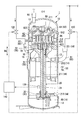
本発明の第一実施形態について、図1から図3を参照して説明する。圧縮機1は、例えば冷凍装置の冷媒回路に接続され、流体として冷媒ガスを圧縮する際に用いられるスクロール圧縮機である。図1に示すように、本実施形態に係る圧縮機1は、ケーシング10と、回転軸20と、軸受部30と、給油ポンプ40と、駆動部50と、圧縮機本体60と、ブッシュアセンブリ70と、複数の吸込管80と、吐出管90と、第一流量調整弁110と、第二流量調整弁120と、センサ部130と、制御部140とを備えている。
本発明の第一実施形態について、図1から図3を参照して説明する。圧縮機1は、例えば冷凍装置の冷媒回路に接続され、流体として冷媒ガスを圧縮する際に用いられるスクロール圧縮機である。図1に示すように、本実施形態に係る圧縮機1は、ケーシング10と、回転軸20と、軸受部30と、給油ポンプ40と、駆動部50と、圧縮機本体60と、ブッシュアセンブリ70と、複数の吸込管80と、吐出管90と、第一流量調整弁110と、第二流量調整弁120と、センサ部130と、制御部140とを備えている。
ケーシング10は、有底筒状をなして密閉構造とされている。ケーシング10の内部には、各種部品は配置される空間が形成されている。ケーシング10は、後述する回転軸20の軸線O1が延びる軸線方向Daに延在している。本実施形態のケーシング10は、軸線方向Daが鉛直方向となるように配置されている。ケーシング10は、回転軸20、軸受部30、給油ポンプ40、駆動部50、圧縮機本体60、ブッシュアセンブリ70、及びセンサ部130を内部に収容している。ケーシング10の底部には、潤滑油が貯留されている。ケーシング10の内部は、圧縮機本体60により、吐出室11と、吸入室12と、に区画されている。吐出室11は、圧縮後の冷却ガスが存在する空間である。吐出室11は、ケーシング10内の圧縮機本体60の上方の空間である。吸入室12は、圧縮前の冷却ガスが存在する空間である。吸入室12は、ケーシング10内の圧縮機本体60の下方の空間である。
回転軸20は、回転軸本体21と、偏心軸22と、を有する。回転軸本体21は、軸線O1を中心とする円柱形状をなしている。回転軸本体21は、ケーシング10内で軸線方向Daに延びている。回転軸本体21は、軸受部30により軸線O1周りに回転可能な状態で支持されている。回転軸本体21の内部には、軸線方向Daの両端で開口するように、回転軸本体21を軸線方向Daに貫通する回転軸本体貫通孔211が形成されている。
偏心軸22は、回転軸本体21の軸線方向Daの一方側(鉛直方向の上方側)の端部に一体に設けられている。偏心軸22は、軸線O1に対してオフセット(偏心)された位置で軸線方向Daに延びる偏心軸線O2を中心軸としている。偏心軸22は、回転軸本体21の外径よりも小さく、軸線方向Daの長さが短い円柱状をなしている。したがって、偏心軸22は、軸線O1回りに回転軸本体21が回転すると、軸線O1回りに公転する。偏心軸22の内部には、偏心軸22を軸線方向Daに貫通する偏心軸貫通孔221が形成されている。偏心軸貫通孔221は、回転軸本体貫通孔211と連通している。
軸受部30は、回転軸20を回転可能に支持している。本実施形態の軸受部30は、メイン軸受31と、サブ軸受32と、ボス軸受33とを有している。
メイン軸受31は、回転軸本体21の軸線方向Daの一方側の端部を回転可能に支持している。メイン軸受31は、ケーシング10の内壁に固定されている。メイン軸受31は、回転軸本体21内に形成されているメイン給油孔212を介して回転軸本体貫通孔211と繋がっている。
サブ軸受32は、回転軸本体21の軸線方向Daの他方側の端部を回転可能に支持している。サブ軸受32は、メイン軸受31よりも軸線方向Daの他方側(鉛直方向の下方側)に配置されている。サブ軸受32は、ケーシング10の内壁に固定されている。サブ軸受32は、回転軸本体21内に形成されているサブ給油孔213を介して回転軸本体貫通孔211と繋がっている。
ボス軸受33は、偏心軸22を覆うように配置されている。したがって、ボス軸受33は、メイン軸受31よりも軸線方向Daの一方側に配置されている。ボス軸受33は、ブッシュアセンブリ70を介して偏心軸22を回転可能に支持している。
給油ポンプ40は、サブ軸受32の下方に設けられている。給油ポンプ40は、ケーシング10内に貯留された潤滑油を汲み上げてメイン軸受31、サブ軸受32、及びボス軸受33に供給する。具体的には、給油ポンプ40は、回転軸本体貫通孔211及び偏心軸貫通孔221を介して回転軸本体21の軸線方向Daの他方側の端面から偏心軸22の軸線方向Daの一方側の端面まで潤滑油を汲み上げている。メイン軸受31にはメイン給油孔212を介して回転軸本体貫通孔211内を流れる潤滑油が供給される。サブ軸受32には、サブ給油孔213を介して回転軸本体貫通孔211内を流れる潤滑油が供給される。ボス軸受33には、偏心軸22の端面から流れ出た運滑油が供給される。
駆動部50は、ケーシング10内において、メイン軸受31とサブ軸受32との軸線方向Daの間に配置されている。駆動部50は、回転軸本体21の中央部の外周面を囲むように配置されている。駆動部50は、回転軸本体21を回転駆動させる。駆動部50としては、例えば、回転軸本体21の外周面に固定されたロータ51と、軸線O1を中心としてロータ51を外周側から囲むステータ52と、を有するモータである。ロータ51は、内部に永久磁石を有し、その外形は軸線O1を中心とする略円筒状をなしている。なお、駆動部50は、回転軸20を回転駆動させることができればよく、モータに限定されるものではない。
圧縮機本体60は、ケーシング10内において、メイン軸受31よりも軸線方向Daの一方側に配置されている。圧縮機本体60は、固定スクロール61と、旋回スクロール62と、を有する。
固定スクロール61は、ケーシング10の内壁に固定されている。固定スクロール61は、固定スクロール端板611と、固定ラップ612と、を有する。
固定スクロール端板611は、ケーシング10に固定された円盤状の板材である。固定スクロール端板611は、旋回スクロール62と対向している。固定スクロール端板611は、吐出口66を有する。吐出口66は、固定スクロール端板611の中央を貫通するように形成された穴である。吐出口66は、圧縮機本体60によって圧縮された高圧の冷媒ガス(高圧流体)を吐出室11に吐出させる。
固定ラップ612は、固定スクロール端板611の軸線方向Daの他方側を向く面(下面)から延びている。固定ラップ612は、軸線方向Daから見て渦巻き状に形成された壁体である。固定ラップ612は、例えば、固定スクロール端板611の中心回りに巻回された板状の部材である。
旋回スクロール62は、固定スクロール61とメイン軸受31との間に配置されている。旋回スクロール62は、旋回スクロール端板621と、旋回ラップ622と、ボス部623と、を有する。
旋回スクロール端板621は、円盤状の板材である。旋回スクロール端板621は、軸線方向Daにおいて固定スクロール端板611と対向している。
旋回ラップ622は、旋回スクロール端板621の軸線方向Daの一方側を向く面から延びている。旋回ラップ622は、軸線方向Daから見て渦巻き状に形成された壁体である。旋回ラップ622は、例えば、旋回スクロール端板621の中心回りに巻回された板状の部材である。
旋回ラップ622は、固定ラップ612と噛み合うように配置されている。これにより、旋回ラップ622と固定ラップ612との間には、流体を圧縮する空間である圧縮室が区画される。旋回ラップ622が固定スクロール61に対して旋回することで、圧縮室の容積が変化する。これにより、圧縮室内の流体(冷媒ガス)が圧縮される。
ボス部623は、回転軸本体21の端面と対向する旋回スクロール端板621の軸線方向Daの他方側を向く面の中央部に設けられている。ボス部623は、円筒形状をなすように、旋回スクロール端板621からメイン軸受31に向かって突出している。ボス部623は、偏心軸22の外周を囲むように配置されている。ボス部623の内周面には、ボス軸受33が固定されている。
ブッシュアセンブリ70は、旋回スクロール62と回転軸20とを連結している。ブッシュアセンブリ70は、ボス部623と偏心軸22との間に設けられている。ブッシュアセンブリ70がボス軸受33に回転可能に支持されることで、ボス部623に対して偏心軸22が回転可能とされている。
また、ケーシング10は、貯留部13と、潤滑油供給経路14と、潤滑油排出経路15と、ガイド部材16とをさらに有している。
貯留部13は、ケーシング10内における潤滑油が貯留された底部の空間である。貯留部13は、ケーシング10内の駆動部50よりも軸線方向Daの他方側の領域の一部である。貯留部13では、貯留された潤滑油内に浸かるように給油ポンプ40が配置されている。
潤滑油供給経路14は、貯留部13からサブ軸受32、メイン軸受31、及びボス軸受33まで潤滑油が供給される際に潤滑油が通過する通路である。本実施形態の潤滑油供給経路14は、給油ポンプ40、回転軸本体貫通孔211、サブ給油孔213、メイン給油孔212、偏心軸貫通孔221である。
潤滑油排出経路15は、サブ軸受32、メイン軸受31、及びボス軸受33で使用された潤滑油が貯留部13に戻る際に潤滑油が通過する通路である。サブ軸受32で使用された潤滑油は、ケーシング10内におけるサブ軸受32と駆動部50との間の空間に流れ出た後に、貯留部13に流れ落ちる。したがって、サブ軸受32で使用された潤滑油が流通する潤滑油排出経路15は、駆動部50に対して軸線方向Daの他方側の空間である。また、メイン軸受31及びボス軸受33で使用された潤滑油は、メイン軸受31と駆動部50との間の空間に流れ出る。その後に、潤滑油は、駆動部50とケーシング10の内壁との間を流れて、貯留部13に流れ落ちる。したがって、メイン軸受31及びボス軸受33で使用された潤滑油が流通する潤滑油排出経路15は、メイン軸受31と駆動部50との間の空間と、駆動部50とケーシング10の内壁との間の空間と、駆動部50に対して軸線方向Daの他方側の空間とである。
ガイド部材16は、潤滑油排出経路15の一部を形成するとともに、潤滑油を貯留部13に導く部材である。ガイド部材16は、メイン軸受31と駆動部50との間の空間に設けられている。ガイド部材16は、ケーシング10に固定されている。本実施形態のガイド部材16は、板状の部材によって形成されている。ガイド部材16は、メイン軸受31と駆動部50との間の空間に流れ出た潤滑油を駆動部50上に直接流れ落ちないように、ケーシング10の内壁に向かって導いている。したがって、メイン軸受31と駆動部50との間の空間に流れ出た潤滑油は、ガイド部材16に沿って駆動部50とケーシング10の内壁との間の空間まで流れる。
吸込管80は、ケーシング10の外部の供給源(例えば、アキュムレータ、不図示)からケーシング10内に圧縮前の冷媒ガスを導入させる配管である。吸込管80は、第一吸込管81と、第二吸込管82とを有する。なお、吸込管80からは冷媒ガスのような気体のみが導入され、液相の冷媒や潤滑油等の液体をケーシング10内に導入する際には他の配管(不図示)が用いられる。
第一吸込管81には、供給源から供給されてきた冷媒ガスが流れ込んでくる。第一吸込管81は、圧縮機本体60における冷媒ガスの流入口である吸込口65に対して、軸線方向Daに離れた位置であって、圧縮機本体60よりも駆動部50に近い位置で、ケーシング10に接続されている。具体的には、第一吸込管81は、駆動部50とメイン軸受31との間であって、軸線方向Daにおいてメイン軸受31よりも駆動部50に近い位置でケーシング10に接続されている。
第二吸込管82には、第一吸込管81と同様に、供給源から供給されてきた冷媒ガスが流れ込んでくる。したがって、第二吸込管82を流れる冷媒ガスの成分と、第一吸込管81を流れる冷媒ガスの成分とは同じである。第二吸込管82は、第一吸込管81におけるケーシング10に対する接続位置に対して、相対的に潤滑油に接触しやすい位置でケーシング10に接続されている。具体的には、本実施形態の第二吸込管82は、メイン軸受31と駆動部50との間であって、軸線方向Daにおいてガイド部材16と重なる位置で、ケーシング10と接続されている。これにより、第二吸込管82は、潤滑油排出経路15に面する位置でケーシング10と接続されている。第二吸込管82は、軸線方向Daにおいて、駆動部50よりもメイン軸受31に近い位置でケーシング10に接続されている。したがって、本実施形態の第二吸込管82は、吸込口65に対して第一吸込管81よりも近い位置でケーシング10と接続されている。
また、図2に示すように、第二吸込管82は、軸線方向Daから見た際に、軸線O1を中心とする周方向の位置が第一吸込管81と重ならないように異なる位置に設けられている。図3に示すように、第二吸込管82の管径は、第一吸込管81の管径よりも小さい。第二吸込管82の管径は、第一吸込管81の管径の半分未満であることが好ましい。具体的には、第一吸込管81の管径がφ20程度の場合、第二吸込管82の管径はφ10未満となる。
吐出管90は、ケーシング10の軸線方向Daの一方側の端部である頂部に設けられている。吐出管90は、吐出室11と連通されている。吐出管90からは、圧縮機本体60で圧縮されて吐出口66から吐出室11に出された高圧の冷媒ガスが排出される。吐出管90は、圧縮された冷媒ガスの使用先(例えば、室内機、不図示)と接続されている。
第一流量調整弁110は、第一吸込管81を流通する流体の流量を調整可能している。第一流量調整弁110は、開放されることによって第一吸込管81からケーシング10内へ冷媒ガスを流入させる。第一流量調整弁110は、閉塞されることによって第一吸込管81からケーシング10内への冷媒ガスの流入を停止させる。
第二流量調整弁120は、第二吸込管82を流通する流体の流量を調整可能している。第二流量調整弁120は、開放されることによって第二吸込管82からケーシング10内へ冷媒ガスを流入させる。第二流量調整弁120は、閉塞されることによって第二吸込管82からケーシング10内への冷媒ガスの流入を停止させる。
センサ部130は、回転軸20の回転数及び圧縮機本体60の圧力の少なくとも一方を測定可能な測定装置である。本実施形態のセンサ部130は、例えば、回転軸本体21の回転数を測定する装置である。センサ部130はケーシング10内に配置されている。センサ部130は、測定結果のデータを制御部140に出力している。
制御部140は、センサ部130での測定結果に応じて第一流量調整弁110及び第二流量調整弁120の開度を調整させる。制御部140では、入力された測定結果が予め定めた条件を満たした場合に、第一流量調整弁110及び第二流量調整弁120を開放又は閉塞させる。具体的には、制御部140は、測定結果として入力された回転数が予め定めた上限基準値を上回った場合に、第一流量調整弁110に開放させる指示を送る。この際、制御部140は、第二流量調整弁120には閉塞させる指示を送る。これにより、回転数が上限基準値を上回った場合には、第二吸込管82からケーシング10内に冷媒ガスは流入されずに、第一吸込管81のみから冷媒ガスが流入される。つまり、回転数が上限基準値を上回った場合には、第一吸込管81から供給される冷媒ガスの流量が第二吸込管82から供給される冷媒ガスの流量よりも多くなる。
また、制御部140は、測定結果として入力された回転数が予め定めた下限基準値を下回った場合に、第二流量調整弁120に開放させる指示を送る。この際、制御部140は、第一流量調整弁110には閉塞させる指示を送る。これにより、回転数が下限基準値を下回った場合には、第一吸込管81からケーシング内に冷媒ガスは流入されずに、第二吸込管82のみから冷媒ガスが流入される。つまり、回転数が下限基準値を下回った場合には、第二吸込管82から供給される冷媒ガスの流量が第一吸込管81から供給される冷媒ガスの流量よりも多くなる。
また、制御部140は、測定結果として入力された回転数が上限基準値以下かつ下限基準値以上となった場合には、第一流量調整弁110及び第二流量調整弁120の両方を開放させるように、それぞれに開放させる指示を送る。これにより、回転数が上限基準値と下限基準値との間となっている場合には、第一吸込管81及び第二吸込管82の両方からケーシング10内に冷媒ガスが流入される。この状態でも、第一吸込管81の方が第二吸込管82よりも管径が大きいことで、第一吸込管81から供給される冷媒ガスの流量が第二吸込管82から供給される冷媒ガスの流量よりも多くなる。
ここで、上限基準値とは、圧縮機本体60が高速運転になっているとみなせる回転軸20の回転数である。逆に下限基準値とは、圧縮機本体60が低速運転になっているとみなせる回転軸20の回転数である。
上記のような圧縮機1によれば、吸込管80として、第一吸込管81及び第二吸込管82が設けられている。複数の吸込管80が設けられていることで、一つの吸込管80のみが設けられている場合に比べて、一つ一つの吸込管80から流入する冷媒ガスの影響を抑えることができる。その結果、一つ一つの吸込管80から供給される冷媒ガスによるOCRの変動を抑えることができる。
さらに、第一吸込管81に対して第二吸込管82の方が、相対的に潤滑油に接触しやすい位置でケーシング10に接続されている。そのため、第一吸込管81から流入した冷媒ガスよりも第二吸込管82から流入した冷媒ガスの方が圧縮機本体60の吸込口65に到達するまでに潤滑油を多く含んだ状態となる。つまり、第一吸込管81から供給された冷媒ガスと、第二吸込管82から供給された冷媒ガスとでは、潤滑油量がそれぞれ異なった状態で圧縮機本体60の吸込口65に送られる。異なる量の潤滑油を含む冷媒ガスが供給できることで、OCRを増減させて調整することが容易となる。その結果、ケーシング10内のOCRを管理しやすくなる。したがって、圧縮機本体60の運転状態に関わらず、潤滑油の供給状態を適切な状態に維持することができる。
また、第一吸込管81よりも第二吸込管82の管径が小さくされている。そのため、第二吸込管82よりも第一吸込管81から多くの冷媒ガスがケーシング10内に流入する。したがって、潤滑油を多く含んだ冷媒ガスの供給量よりも、潤滑油があまり含まれていない冷媒ガスの供給量が多くなる。圧縮機本体60の高速運転時には、OCRの数値が上がりやすくなるため、潤滑油があまり含まれていない冷媒ガスが供給されることが好ましい。さらに、高速運転時には、圧縮機本体60を最大限効率よく使用するために、多くの冷媒ガスが供給されることが好ましい。したがって、第一吸込管81によって潤滑油があまり含まれていない冷媒ガスが多く供給されることで、高速運転時の圧縮機本体60の運転性能を安定させることができる。
また、第一吸込管81は、圧縮機本体60の吸込口65に対して軸線方向Daに大きく離れるように、圧縮機本体60よりも駆動部50に近い位置でケーシング10に接続されている。さらに、第一吸込管81は、貯留部13と軸受部30との間の潤滑油の流通経路である潤滑油供給経路14から外れた位置でケーシング10に接続されている。そのため、第一吸込管81からケーシング10内に供給された冷媒ガス中に潤滑油が含まれていたとしても、吸込口65に到達するまでの間に冷媒ガスから潤滑油が分離される。その結果、より潤滑油が含まれていない状態の冷媒ガスを吸込口65に供給することができる。
また、第二吸込管82のケーシング10との接続位置は、潤滑油排出経路15に面するように配置されている。そのため、第二吸込管82からケーシング10内に供給された冷媒ガスは、潤滑油排出経路15を流通する潤滑油中を通過した後に吸込口65に到達する。これにより、第二吸込管82からケーシング10内に流入した冷媒ガスに含まれる潤滑油量が増加する。したがって、多くの潤滑油が含まれた状態の冷媒ガスを吸込口65に供給することができる。
また、潤滑油供給経路14のように軸受部30に供給される直前の潤滑油ではなく、軸受部30で使用後の潤滑油が流れている潤滑油排出経路15に冷媒ガスを通過させている。その結果、軸受部30への潤滑油の供給量が減る等の軸受部30の信頼性を損なうような不具合の発生を抑えることができる。したがって、軸受部30の信頼性を維持することができる。
また、第二吸込管82は、潤滑油排出経路15に面する位置の中でも、軸線方向Daにおいてガイド部材16と重なる位置でケーシング10と接続されている。そのため、第二吸込管82からケーシング10内に流入した冷媒ガスは、ガイド部材16とケーシング10の内壁との間を流れる潤滑油中を通過する。したがって、冷媒ガスは、より潤滑油と接触しやすくなる。これにより、より多く潤滑油を含む冷媒ガスを吸込口65に供給することができる。
また、第一流量調整弁110によって第一吸込管81を流通する冷媒ガスの流量が調整可能とされている。さらに、第二流量調整弁120によって第二吸込管82を流通する冷媒ガスの流量が調整可能とされている。この第一流量調整弁110及び第二流量調整弁120の開閉は、制御部140によって回転軸本体21の回転数に応じて制御されている。回転軸本体21の回転数に応じて、第一流量調整弁110及び第二流量調整弁120の開閉が制御される。これにより、圧縮機本体60の運転状態に応じて第一吸込管81及び第二吸込管82のどちらから冷媒ガスが供給されるかを調整することができる。したがって、圧縮機本体60の運転状態に応じて第一吸込管81から供給される冷媒ガスの供給量及び第二吸込管82から供給される冷媒ガスの供給量を調整することができる。
特に、本実施形態では、回転数が上限基準値を上回った場合に、第一流量調整弁110が開放され、第二流量調整弁120が閉塞されている。そのため、圧縮機本体60が高速運転となった場合に、潤滑油を多く含む冷媒ガスが供給されなくなり、潤滑油をほとんど含まない冷媒ガスのみが吸込口65に供給される。そのため、圧縮機本体60が高速運転となった場合に、潤滑油の供給量を抑え、OCRが上昇しすぎてしまうことを抑えることができる。
また、回転数が下限基準値を下回った場合に、第二流量調整弁120が開放され、第一流量調整弁110が閉塞されている。そのため、圧縮機本体60が低速運転となった場合に、潤滑油をほとんど含まない冷媒ガスが供給されなくなり、潤滑油を多く含む冷媒ガスのみが吸込口65に供給される。そのため、圧縮機本体60が低速運転となった場合に、潤滑油の供給量を増加させ、OCRが下降しすぎてしまうことを抑えることができる。
《第二実施形態》
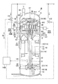
次に、本発明の第二実施形態の圧縮機について図4及び図5を参照して説明する。第二実施形態で示す圧縮機では、第二吸込管のケーシングへの接続位置が第一実施形態と異なっている。したがって、第二実施形態の説明においては、第一実施形態と同一部分に同一符号を付して説明するとともに重複説明を省略する。
次に、本発明の第二実施形態の圧縮機について図4及び図5を参照して説明する。第二実施形態で示す圧縮機では、第二吸込管のケーシングへの接続位置が第一実施形態と異なっている。したがって、第二実施形態の説明においては、第一実施形態と同一部分に同一符号を付して説明するとともに重複説明を省略する。
図4及び図5に示すように、第二実施形態の圧縮機1Aでは、吸込管80Aは、第一吸込管81と、第二吸込管82Aとを有する。第二吸込管82Aは、貯留部13に面する位置でケーシング10と接続されている。したがって、第二吸込管82Aのケーシング10との接続位置は、貯留部13に貯留されている潤滑油の液面よりも軸線方向Daの他方側(鉛直方向の下方側)に配置されている。つまり、第二実施形態の第二吸込管82Aは、吸込口65に対して第一吸込管81よりも遠い位置でケーシング10と接続されている。第二吸込管82Aからケーシング10内に供給された冷媒ガスは、貯留された潤滑油内に送り込まれる。
第二実施形態の圧縮機1Aによれば、第二吸込管82Aからケーシング10内に供給された冷媒ガスは、貯留部13に貯留されている潤滑油内を通過した後に、吸込口65に到達する。これにより、第二吸込管82Aからケーシング10内に流入した冷媒ガスに含まれる潤滑油量が大きく増加する。したがって、多くの潤滑油が含まれた状態の冷媒ガスを吸込口65に供給することができる。
また、貯留部13のように軸受部30に供給される直前の潤滑油ではなく、軸受部30で使用後に貯留された潤滑油に冷媒ガスを通過させている。その結果、軸受部30への潤滑油の供給量が減る等の軸受部30の信頼性を損なうような不具合の発生を抑えることができる。したがって、軸受部30の信頼性を維持することができる。
《第三実施形態》
次に、本発明の第三実施形態の圧縮機について図6を参照して説明する。第三実施形態で示す圧縮機では、第一吸込管のケーシングへの接続位置及び第一吸込管の数が第一実施形態と異なっている。したがって、第三実施形態の説明においては、第一実施形態と同一部分に同一符号を付して説明するとともに重複説明を省略する。
次に、本発明の第三実施形態の圧縮機について図6を参照して説明する。第三実施形態で示す圧縮機では、第一吸込管のケーシングへの接続位置及び第一吸込管の数が第一実施形態と異なっている。したがって、第三実施形態の説明においては、第一実施形態と同一部分に同一符号を付して説明するとともに重複説明を省略する。
図6に示すように、第三実施形態の圧縮機1Bでは、吸込管80Bは、複数(二つ)の第一吸込管81Bと、第二吸込管82とを有している。第一吸込管81Bは、吸込口65に対して、回転軸20を中心とする径方向の外側でケーシング10に接続されている。第一吸込管81Bは、軸線方向Daにおいて、メイン軸受31よりも軸線方向Daの一方側でケーシング10に接続されている。したがって、第三実施形態の第一吸込管81Bは、吸込口65に対して第二吸込管82よりも近い位置でケーシング10と接続されている。二つの第一吸込管81Bは、周方向の位置が互いに180°異なるように配置されている。
第三実施形態の圧縮機1Bによれば、第一吸込管81Bからケーシング10内に供給された冷媒ガスは、ケーシング10内における潤滑油が流れている空間を通らずに、最短距離で吸込口65に供給される。そのため、第一吸込管81Bからケーシング10内に流入した冷媒ガスにケーシング10内を流れる潤滑油が巻き込まれてしまうことを抑えることができる。その結果、より潤滑油が含まれていない状態の冷媒ガスを吸込口65に供給することができる。
また、第二吸込管82よりも第一吸込管81Bの数が多いことで、潤滑油を多く含む冷媒ガスの供給量に比べて、潤滑油が含まれていない冷媒ガスの供給量が多くなる。そのため、例えば、圧縮機本体60が高速運転時に多量の冷媒ガスを必要とするような大容量のスクロール圧縮機であっても、潤滑油の供給状態を適切な状態に維持することができる。
(実施形態の他の変形例)
以上、本発明の実施形態について図面を参照して詳述したが、各実施形態における各構成及びそれらの組み合わせ等は一例であり、本発明の趣旨から逸脱しない範囲内で、構成の付加、省略、置換、及びその他の変更が可能である。また、本発明は実施形態によって限定されることはなく、特許請求の範囲によってのみ限定される。
以上、本発明の実施形態について図面を参照して詳述したが、各実施形態における各構成及びそれらの組み合わせ等は一例であり、本発明の趣旨から逸脱しない範囲内で、構成の付加、省略、置換、及びその他の変更が可能である。また、本発明は実施形態によって限定されることはなく、特許請求の範囲によってのみ限定される。
即ち、本発明の圧縮機1,1A,1Bは、上述した実施形態のいずれかが組み合わされた構成であってもよい。例えば、第三実施形態の変形例の圧縮機1Cでは、図7に示すように、吸込管80Cは、第一吸込管81B及び第二吸込管82を一つずつ有していてもよい。したがって、変形例の圧縮機1Cでは、第一吸込管81Bとして、吸込口65に直接連通するように、吸込口65の真横でケーシング10に接続されたもののみが設けられている。この変形例では、第一吸込管81Bから流入した冷媒ガスは、ケーシング10内を流れることなく吸込口65にほぼ直接流入される。このように、第一吸込管81,81B及び第二吸込管82,82Aは、それぞれ一つのみ設けられていてもよく、ともに複数設けられていてもよく、第三実施形態のように片方のみが複数設けられていてもよい。
また、圧縮機本体60は、本実施形態のようにスクロール圧縮機であることに限定されるものではない。圧縮機本体60は、例えばロータリ圧縮機であってもよい。
また、ガイド部材16は、本実施形態のような形状に限定ざれるものではない。ガイド部材16は、潤滑油が駆動部50上に直接流れ落ちないように、貯留部13に潤滑油を導くことができればよい。したがって、ガイド部材16は、例えば、筒状の配管であってもよい。この際、第二吸込管82は、例えば、筒状の配管の出口付近でケーシング10と接続される。
また、第一流量調整弁110及び第二流量調整弁120は、完全に開放されるか完全に閉塞されるかのように開度が調整されることに限定されるものではない。第一流量調整弁110及び第二流量調整弁120は、ある程度の冷媒ガスを流通させるように流量を絞ったり、開放させたりするように開度が調整されてもよい。
また、センサ部130は、回転数を測定する装置であることに限定されるものではない。センサ部130は、圧縮機本体60の運転状態を検知することができる装置であればよい。したがって、センサ部130は、例えば、圧縮機本体60の吐出口66から排出される圧縮された冷媒ガスの圧力やケーシング10内の圧力を測定する装置であってもよい。
本発明によれば、潤滑油の供給状態を適切な状態に維持することができる。
1,1A,1B,1C 圧縮機
10 ケーシング
11 吐出室
12 吸入室
13 貯留部
14 潤滑油供給経路
15 潤滑油排出経路
16 ガイド部材
20 回転軸
21 回転軸本体
211 回転軸本体貫通孔
212 メイン給油孔
213 サブ給油孔
22 偏心軸
221 偏心軸貫通孔
O1 軸線
O2 偏心軸線
Da 軸線方向
30 軸受部
31 メイン軸受
32 サブ軸受
33 ボス軸受
40 給油ポンプ
50 駆動部
51 ロータ
52 ステータ
60 圧縮機本体
61 固定スクロール
611 固定スクロール端板
612 固定ラップ
62 旋回スクロール
621 旋回スクロール端板
622 旋回ラップ
623 ボス部
65 吸込口
66 吐出口
70 ブッシュアセンブリ
80,80A,80B,80C 吸込管
81,81B 第一吸込管
82,82A 第二吸込管
90 吐出管
110 第一流量調整弁
120 第二流量調整弁
130 センサ部
140 制御部
10 ケーシング
11 吐出室
12 吸入室
13 貯留部
14 潤滑油供給経路
15 潤滑油排出経路
16 ガイド部材
20 回転軸
21 回転軸本体
211 回転軸本体貫通孔
212 メイン給油孔
213 サブ給油孔
22 偏心軸
221 偏心軸貫通孔
O1 軸線
O2 偏心軸線
Da 軸線方向
30 軸受部
31 メイン軸受
32 サブ軸受
33 ボス軸受
40 給油ポンプ
50 駆動部
51 ロータ
52 ステータ
60 圧縮機本体
61 固定スクロール
611 固定スクロール端板
612 固定ラップ
62 旋回スクロール
621 旋回スクロール端板
622 旋回ラップ
623 ボス部
65 吸込口
66 吐出口
70 ブッシュアセンブリ
80,80A,80B,80C 吸込管
81,81B 第一吸込管
82,82A 第二吸込管
90 吐出管
110 第一流量調整弁
120 第二流量調整弁
130 センサ部
140 制御部
Claims (9)
- 軸線に沿って延在する回転軸と、
前記回転軸を回転可能に支持する軸受部と、
前記回転軸を回転駆動させる駆動部と、
前記回転軸によって回転することで流体を圧縮する圧縮機本体と、
前記回転軸、前記駆動部及び圧縮機本体を収容し、前記軸受部を潤滑する潤滑油が内部に貯留されているケーシングと、
前記ケーシング内に圧縮前の流体を供給する複数の吸込管とを備え、
前記複数の吸込管は、
前記ケーシングに接続された第一吸込管と、
前記第一吸込管における前記ケーシングに対する接続位置に対して、相対的に前記潤滑油に接触しやすい位置で前記ケーシングに接続された第二吸込管とを有する圧縮機。 - 前記第一吸込管の管径よりも前記第二吸込管の管径が小さい請求項1に記載の圧縮機。
- 前記第一吸込管は、前記圧縮機本体の吸込口に対して、前記回転軸の延びる軸線方向に離れた位置であって、前記圧縮機本体よりも前記駆動部に近い位置で前記ケーシングに接続されている請求項1または請求項2に記載の圧縮機。
- 前記第一吸込管は、前記圧縮機本体の吸込口に対して、前記回転軸を中心とする径方向の外側で前記ケーシングに接続されている請求項1から請求項3の何れか一項に記載の圧縮機。
- 前記ケーシングは、
前記潤滑油が貯留された貯留部と、
前記貯留部から前記軸受部まで前記潤滑油が供給される潤滑油供給経路と、
前記軸受部で使用された前記潤滑油を前記軸受部から前記貯留部に送る潤滑油排出経路とを有し、
前記第二吸込管は、前記潤滑油排出経路及び前記貯留部の少なくとも一方に面する位置で前記ケーシングと接続されている請求項1から請求項4の何れか一項に記載の圧縮機。 - 前記ケーシングは、前記潤滑油排出経路の一部を形成するとともに、前記潤滑油を前記貯留部に導くガイド部材を有し、
前記第二吸込管は、前記回転軸の延びる軸線方向において、前記ガイド部材と重なる位置で前記ケーシングと接続されている請求項5に記載の圧縮機。 - 前記第一吸込管を流通する前記流体の流量を調整可能な第一流量調整弁と、
前記第二吸込管を流通する前記流体の流量を調整可能な第二流量調整弁と、
前記回転軸の回転数及び前記圧縮機本体の圧力の少なくとも一方に応じて、前記第一流量調整弁及び前記第二流量調整弁の開度を調整する制御部を備える請求項1から請求項6の何れか一項に記載の圧縮機。 - 前記制御部は、前記回転数及び前記圧力の少なくとも一方が予め定めた上限基準値を上回った場合に、前記第一吸込管から供給される前記流体の流量が前記第二吸込管から供給される前記流体の流量よりも多くなるように前記第一流量調整弁及び前記第二流量調整弁の開度を調整する請求項7に記載の圧縮機。
- 前記制御部は、前記回転数及び前記圧力の少なくとも一方が予め定めた下限基準値を下回った場合に、前記第一吸込管から供給される前記流体の流量が前記第二吸込管から供給される前記流体の流量よりも少なくなるように前記第一流量調整弁及び前記第二流量調整弁の開度を調整する請求項7又は請求項8に記載の圧縮機。
Applications Claiming Priority (2)
| Application Number | Priority Date | Filing Date | Title |
|---|---|---|---|
| JP2018124789A JP7143128B2 (ja) | 2018-06-29 | 2018-06-29 | 圧縮機 |
| JP2018-124789 | 2018-06-29 |
Publications (1)
| Publication Number | Publication Date |
|---|---|
| WO2020004359A1 true WO2020004359A1 (ja) | 2020-01-02 |
Family
ID=68987161
Family Applications (1)
| Application Number | Title | Priority Date | Filing Date |
|---|---|---|---|
| PCT/JP2019/025055 Ceased WO2020004359A1 (ja) | 2018-06-29 | 2019-06-25 | 圧縮機 |
Country Status (2)
| Country | Link |
|---|---|
| JP (1) | JP7143128B2 (ja) |
| WO (1) | WO2020004359A1 (ja) |
Cited By (1)
| Publication number | Priority date | Publication date | Assignee | Title |
|---|---|---|---|---|
| CN114658857A (zh) * | 2020-12-23 | 2022-06-24 | 丹佛斯(天津)有限公司 | 流量控制阀、具有流量控制阀的油泵组件以及涡旋压缩机 |
Citations (4)
| Publication number | Priority date | Publication date | Assignee | Title |
|---|---|---|---|---|
| JPH062680A (ja) * | 1992-06-17 | 1994-01-11 | Mitsubishi Heavy Ind Ltd | 密閉型電動圧縮機 |
| JP2568711B2 (ja) * | 1989-12-29 | 1997-01-08 | 松下電器産業株式会社 | 気体圧縮機 |
| JP2004084633A (ja) * | 2002-08-29 | 2004-03-18 | Calsonic Compressor Seizo Kk | 気体圧縮機のオイル戻し制御装置 |
| US20160186754A1 (en) * | 2014-12-31 | 2016-06-30 | Samsung Electronics Co., Ltd. | Scroll compressor and air conditioner having the same |
-
2018
- 2018-06-29 JP JP2018124789A patent/JP7143128B2/ja active Active
-
2019
- 2019-06-25 WO PCT/JP2019/025055 patent/WO2020004359A1/ja not_active Ceased
Patent Citations (4)
| Publication number | Priority date | Publication date | Assignee | Title |
|---|---|---|---|---|
| JP2568711B2 (ja) * | 1989-12-29 | 1997-01-08 | 松下電器産業株式会社 | 気体圧縮機 |
| JPH062680A (ja) * | 1992-06-17 | 1994-01-11 | Mitsubishi Heavy Ind Ltd | 密閉型電動圧縮機 |
| JP2004084633A (ja) * | 2002-08-29 | 2004-03-18 | Calsonic Compressor Seizo Kk | 気体圧縮機のオイル戻し制御装置 |
| US20160186754A1 (en) * | 2014-12-31 | 2016-06-30 | Samsung Electronics Co., Ltd. | Scroll compressor and air conditioner having the same |
Cited By (2)
| Publication number | Priority date | Publication date | Assignee | Title |
|---|---|---|---|---|
| CN114658857A (zh) * | 2020-12-23 | 2022-06-24 | 丹佛斯(天津)有限公司 | 流量控制阀、具有流量控制阀的油泵组件以及涡旋压缩机 |
| US11885327B2 (en) | 2020-12-23 | 2024-01-30 | Danfoss (Tianjin) Ltd. | Flow control valve, oil pump assembly having the flow control valve, and scroll compressor |
Also Published As
| Publication number | Publication date |
|---|---|
| JP2020002906A (ja) | 2020-01-09 |
| JP7143128B2 (ja) | 2022-09-28 |
Similar Documents
| Publication | Publication Date | Title |
|---|---|---|
| WO2013118514A1 (ja) | 圧縮機 | |
| WO2010087179A1 (ja) | スクロール圧縮機 | |
| US20160186754A1 (en) | Scroll compressor and air conditioner having the same | |
| JP2018021493A (ja) | スクロール圧縮機 | |
| WO2021005895A1 (ja) | スクロール圧縮機 | |
| JP6762253B2 (ja) | 回転式圧縮機及び冷凍サイクル装置 | |
| JP6180630B2 (ja) | 圧縮機 | |
| JP2008180094A (ja) | スクロール型流体機械 | |
| JP2007138868A (ja) | スクロール圧縮機 | |
| JP7143128B2 (ja) | 圧縮機 | |
| WO2017086105A1 (ja) | スクロール圧縮機 | |
| JP7130133B2 (ja) | スクロール圧縮機および冷凍サイクル装置 | |
| JP5493958B2 (ja) | 圧縮機 | |
| JP5863436B2 (ja) | 流体機械 | |
| WO2016170615A1 (ja) | スクロール圧縮機 | |
| KR20130092769A (ko) | 스크롤 압축기 | |
| JP2000179472A (ja) | ロータリ圧縮機 | |
| JP5143041B2 (ja) | 圧縮機 | |
| JP2003286976A (ja) | スクロール型圧縮機 | |
| JP5304679B2 (ja) | 圧縮機 | |
| US12196208B2 (en) | Compressor | |
| KR20190000687A (ko) | 윤활 성능을 개선한 압축기 | |
| CN106414900A (zh) | 涡旋式压缩机 | |
| JP2009057892A (ja) | 圧縮機及び冷凍装置 | |
| JP4807332B2 (ja) | 圧縮機 |
Legal Events
| Date | Code | Title | Description |
|---|---|---|---|
| 121 | Ep: the epo has been informed by wipo that ep was designated in this application |
Ref document number: 19825962 Country of ref document: EP Kind code of ref document: A1 |
|
| NENP | Non-entry into the national phase |
Ref country code: DE |
|
| 32PN | Ep: public notification in the ep bulletin as address of the adressee cannot be established |
Free format text: NOTING OF LOSS OF RIGHTS PURSUANT TO RULE 112(1) EPC (EPO FORM 1205A DATED 29/03/2021) |
|
| 122 | Ep: pct application non-entry in european phase |
Ref document number: 19825962 Country of ref document: EP Kind code of ref document: A1 |