WO2020004413A1 - 蓄電装置用外装材及びこれを用いた蓄電装置 - Google Patents
蓄電装置用外装材及びこれを用いた蓄電装置 Download PDFInfo
- Publication number
- WO2020004413A1 WO2020004413A1 PCT/JP2019/025223 JP2019025223W WO2020004413A1 WO 2020004413 A1 WO2020004413 A1 WO 2020004413A1 JP 2019025223 W JP2019025223 W JP 2019025223W WO 2020004413 A1 WO2020004413 A1 WO 2020004413A1
- Authority
- WO
- WIPO (PCT)
- Prior art keywords
- layer
- peak temperature
- resin
- melting peak
- exterior material
- Prior art date
- Legal status (The legal status is an assumption and is not a legal conclusion. Google has not performed a legal analysis and makes no representation as to the accuracy of the status listed.)
- Ceased
Links
Images
Classifications
-
- B—PERFORMING OPERATIONS; TRANSPORTING
- B32—LAYERED PRODUCTS
- B32B—LAYERED PRODUCTS, i.e. PRODUCTS BUILT-UP OF STRATA OF FLAT OR NON-FLAT, e.g. CELLULAR OR HONEYCOMB, FORM
- B32B7/00—Layered products characterised by the relation between layers; Layered products characterised by the relative orientation of features between layers, or by the relative values of a measurable parameter between layers, i.e. products comprising layers having different physical, chemical or physicochemical properties; Layered products characterised by the interconnection of layers
- B32B7/04—Interconnection of layers
- B32B7/12—Interconnection of layers using interposed adhesives or interposed materials with bonding properties
-
- H—ELECTRICITY
- H01—ELECTRIC ELEMENTS
- H01M—PROCESSES OR MEANS, e.g. BATTERIES, FOR THE DIRECT CONVERSION OF CHEMICAL ENERGY INTO ELECTRICAL ENERGY
- H01M50/00—Constructional details or processes of manufacture of the non-active parts of electrochemical cells other than fuel cells, e.g. hybrid cells
- H01M50/10—Primary casings; Jackets or wrappings
- H01M50/116—Primary casings; Jackets or wrappings characterised by the material
- H01M50/124—Primary casings; Jackets or wrappings characterised by the material having a layered structure
-
- B—PERFORMING OPERATIONS; TRANSPORTING
- B32—LAYERED PRODUCTS
- B32B—LAYERED PRODUCTS, i.e. PRODUCTS BUILT-UP OF STRATA OF FLAT OR NON-FLAT, e.g. CELLULAR OR HONEYCOMB, FORM
- B32B15/00—Layered products comprising a layer of metal
- B32B15/04—Layered products comprising a layer of metal comprising metal as the main or only constituent of a layer, which is next to another layer of the same or of a different material
- B32B15/08—Layered products comprising a layer of metal comprising metal as the main or only constituent of a layer, which is next to another layer of the same or of a different material of synthetic resin
- B32B15/088—Layered products comprising a layer of metal comprising metal as the main or only constituent of a layer, which is next to another layer of the same or of a different material of synthetic resin comprising polyamides
-
- B—PERFORMING OPERATIONS; TRANSPORTING
- B32—LAYERED PRODUCTS
- B32B—LAYERED PRODUCTS, i.e. PRODUCTS BUILT-UP OF STRATA OF FLAT OR NON-FLAT, e.g. CELLULAR OR HONEYCOMB, FORM
- B32B15/00—Layered products comprising a layer of metal
- B32B15/04—Layered products comprising a layer of metal comprising metal as the main or only constituent of a layer, which is next to another layer of the same or of a different material
- B32B15/08—Layered products comprising a layer of metal comprising metal as the main or only constituent of a layer, which is next to another layer of the same or of a different material of synthetic resin
- B32B15/09—Layered products comprising a layer of metal comprising metal as the main or only constituent of a layer, which is next to another layer of the same or of a different material of synthetic resin comprising polyesters
-
- B—PERFORMING OPERATIONS; TRANSPORTING
- B32—LAYERED PRODUCTS
- B32B—LAYERED PRODUCTS, i.e. PRODUCTS BUILT-UP OF STRATA OF FLAT OR NON-FLAT, e.g. CELLULAR OR HONEYCOMB, FORM
- B32B15/00—Layered products comprising a layer of metal
- B32B15/04—Layered products comprising a layer of metal comprising metal as the main or only constituent of a layer, which is next to another layer of the same or of a different material
- B32B15/08—Layered products comprising a layer of metal comprising metal as the main or only constituent of a layer, which is next to another layer of the same or of a different material of synthetic resin
- B32B15/092—Layered products comprising a layer of metal comprising metal as the main or only constituent of a layer, which is next to another layer of the same or of a different material of synthetic resin comprising epoxy resins
-
- B—PERFORMING OPERATIONS; TRANSPORTING
- B32—LAYERED PRODUCTS
- B32B—LAYERED PRODUCTS, i.e. PRODUCTS BUILT-UP OF STRATA OF FLAT OR NON-FLAT, e.g. CELLULAR OR HONEYCOMB, FORM
- B32B15/00—Layered products comprising a layer of metal
- B32B15/04—Layered products comprising a layer of metal comprising metal as the main or only constituent of a layer, which is next to another layer of the same or of a different material
- B32B15/08—Layered products comprising a layer of metal comprising metal as the main or only constituent of a layer, which is next to another layer of the same or of a different material of synthetic resin
- B32B15/095—Layered products comprising a layer of metal comprising metal as the main or only constituent of a layer, which is next to another layer of the same or of a different material of synthetic resin comprising polyurethanes
-
- B—PERFORMING OPERATIONS; TRANSPORTING
- B32—LAYERED PRODUCTS
- B32B—LAYERED PRODUCTS, i.e. PRODUCTS BUILT-UP OF STRATA OF FLAT OR NON-FLAT, e.g. CELLULAR OR HONEYCOMB, FORM
- B32B15/00—Layered products comprising a layer of metal
- B32B15/04—Layered products comprising a layer of metal comprising metal as the main or only constituent of a layer, which is next to another layer of the same or of a different material
- B32B15/08—Layered products comprising a layer of metal comprising metal as the main or only constituent of a layer, which is next to another layer of the same or of a different material of synthetic resin
- B32B15/098—Layered products comprising a layer of metal comprising metal as the main or only constituent of a layer, which is next to another layer of the same or of a different material of synthetic resin comprising condensation resins of aldehydes, e.g. with phenols, ureas or melamines
-
- B—PERFORMING OPERATIONS; TRANSPORTING
- B32—LAYERED PRODUCTS
- B32B—LAYERED PRODUCTS, i.e. PRODUCTS BUILT-UP OF STRATA OF FLAT OR NON-FLAT, e.g. CELLULAR OR HONEYCOMB, FORM
- B32B15/00—Layered products comprising a layer of metal
- B32B15/18—Layered products comprising a layer of metal comprising iron or steel
-
- B—PERFORMING OPERATIONS; TRANSPORTING
- B32—LAYERED PRODUCTS
- B32B—LAYERED PRODUCTS, i.e. PRODUCTS BUILT-UP OF STRATA OF FLAT OR NON-FLAT, e.g. CELLULAR OR HONEYCOMB, FORM
- B32B15/00—Layered products comprising a layer of metal
- B32B15/20—Layered products comprising a layer of metal comprising aluminium or copper
-
- B—PERFORMING OPERATIONS; TRANSPORTING
- B32—LAYERED PRODUCTS
- B32B—LAYERED PRODUCTS, i.e. PRODUCTS BUILT-UP OF STRATA OF FLAT OR NON-FLAT, e.g. CELLULAR OR HONEYCOMB, FORM
- B32B27/00—Layered products comprising a layer of synthetic resin
- B32B27/06—Layered products comprising a layer of synthetic resin as the main or only constituent of a layer, which is next to another layer of the same or of a different material
- B32B27/08—Layered products comprising a layer of synthetic resin as the main or only constituent of a layer, which is next to another layer of the same or of a different material of synthetic resin
-
- B—PERFORMING OPERATIONS; TRANSPORTING
- B32—LAYERED PRODUCTS
- B32B—LAYERED PRODUCTS, i.e. PRODUCTS BUILT-UP OF STRATA OF FLAT OR NON-FLAT, e.g. CELLULAR OR HONEYCOMB, FORM
- B32B27/00—Layered products comprising a layer of synthetic resin
- B32B27/28—Layered products comprising a layer of synthetic resin comprising synthetic resins not wholly covered by any one of the sub-groups B32B27/30 - B32B27/42
- B32B27/281—Layered products comprising a layer of synthetic resin comprising synthetic resins not wholly covered by any one of the sub-groups B32B27/30 - B32B27/42 comprising polyimides
-
- B—PERFORMING OPERATIONS; TRANSPORTING
- B32—LAYERED PRODUCTS
- B32B—LAYERED PRODUCTS, i.e. PRODUCTS BUILT-UP OF STRATA OF FLAT OR NON-FLAT, e.g. CELLULAR OR HONEYCOMB, FORM
- B32B27/00—Layered products comprising a layer of synthetic resin
- B32B27/28—Layered products comprising a layer of synthetic resin comprising synthetic resins not wholly covered by any one of the sub-groups B32B27/30 - B32B27/42
- B32B27/283—Layered products comprising a layer of synthetic resin comprising synthetic resins not wholly covered by any one of the sub-groups B32B27/30 - B32B27/42 comprising polysiloxanes
-
- B—PERFORMING OPERATIONS; TRANSPORTING
- B32—LAYERED PRODUCTS
- B32B—LAYERED PRODUCTS, i.e. PRODUCTS BUILT-UP OF STRATA OF FLAT OR NON-FLAT, e.g. CELLULAR OR HONEYCOMB, FORM
- B32B27/00—Layered products comprising a layer of synthetic resin
- B32B27/28—Layered products comprising a layer of synthetic resin comprising synthetic resins not wholly covered by any one of the sub-groups B32B27/30 - B32B27/42
- B32B27/286—Layered products comprising a layer of synthetic resin comprising synthetic resins not wholly covered by any one of the sub-groups B32B27/30 - B32B27/42 comprising polysulphones; polysulfides
-
- B—PERFORMING OPERATIONS; TRANSPORTING
- B32—LAYERED PRODUCTS
- B32B—LAYERED PRODUCTS, i.e. PRODUCTS BUILT-UP OF STRATA OF FLAT OR NON-FLAT, e.g. CELLULAR OR HONEYCOMB, FORM
- B32B27/00—Layered products comprising a layer of synthetic resin
- B32B27/34—Layered products comprising a layer of synthetic resin comprising polyamides
-
- B—PERFORMING OPERATIONS; TRANSPORTING
- B32—LAYERED PRODUCTS
- B32B—LAYERED PRODUCTS, i.e. PRODUCTS BUILT-UP OF STRATA OF FLAT OR NON-FLAT, e.g. CELLULAR OR HONEYCOMB, FORM
- B32B27/00—Layered products comprising a layer of synthetic resin
- B32B27/36—Layered products comprising a layer of synthetic resin comprising polyesters
-
- B—PERFORMING OPERATIONS; TRANSPORTING
- B32—LAYERED PRODUCTS
- B32B—LAYERED PRODUCTS, i.e. PRODUCTS BUILT-UP OF STRATA OF FLAT OR NON-FLAT, e.g. CELLULAR OR HONEYCOMB, FORM
- B32B27/00—Layered products comprising a layer of synthetic resin
- B32B27/38—Layered products comprising a layer of synthetic resin comprising epoxy resins
-
- B—PERFORMING OPERATIONS; TRANSPORTING
- B32—LAYERED PRODUCTS
- B32B—LAYERED PRODUCTS, i.e. PRODUCTS BUILT-UP OF STRATA OF FLAT OR NON-FLAT, e.g. CELLULAR OR HONEYCOMB, FORM
- B32B27/00—Layered products comprising a layer of synthetic resin
- B32B27/40—Layered products comprising a layer of synthetic resin comprising polyurethanes
-
- B—PERFORMING OPERATIONS; TRANSPORTING
- B32—LAYERED PRODUCTS
- B32B—LAYERED PRODUCTS, i.e. PRODUCTS BUILT-UP OF STRATA OF FLAT OR NON-FLAT, e.g. CELLULAR OR HONEYCOMB, FORM
- B32B27/00—Layered products comprising a layer of synthetic resin
- B32B27/42—Layered products comprising a layer of synthetic resin comprising condensation resins of aldehydes, e.g. with phenols, ureas or melamines
-
- H—ELECTRICITY
- H01—ELECTRIC ELEMENTS
- H01G—CAPACITORS; CAPACITORS, RECTIFIERS, DETECTORS, SWITCHING DEVICES, LIGHT-SENSITIVE OR TEMPERATURE-SENSITIVE DEVICES OF THE ELECTROLYTIC TYPE
- H01G11/00—Hybrid capacitors, i.e. capacitors having different positive and negative electrodes; Electric double-layer [EDL] capacitors; Processes for the manufacture thereof or of parts thereof
- H01G11/78—Cases; Housings; Encapsulations; Mountings
- H01G11/80—Gaskets; Sealings
-
- H—ELECTRICITY
- H01—ELECTRIC ELEMENTS
- H01G—CAPACITORS; CAPACITORS, RECTIFIERS, DETECTORS, SWITCHING DEVICES, LIGHT-SENSITIVE OR TEMPERATURE-SENSITIVE DEVICES OF THE ELECTROLYTIC TYPE
- H01G11/00—Hybrid capacitors, i.e. capacitors having different positive and negative electrodes; Electric double-layer [EDL] capacitors; Processes for the manufacture thereof or of parts thereof
- H01G11/78—Cases; Housings; Encapsulations; Mountings
- H01G11/82—Fixing or assembling a capacitive element in a housing, e.g. mounting electrodes, current collectors or terminals in containers or encapsulations
-
- H—ELECTRICITY
- H01—ELECTRIC ELEMENTS
- H01M—PROCESSES OR MEANS, e.g. BATTERIES, FOR THE DIRECT CONVERSION OF CHEMICAL ENERGY INTO ELECTRICAL ENERGY
- H01M10/00—Secondary cells; Manufacture thereof
- H01M10/05—Accumulators with non-aqueous electrolyte
- H01M10/052—Li-accumulators
-
- H—ELECTRICITY
- H01—ELECTRIC ELEMENTS
- H01M—PROCESSES OR MEANS, e.g. BATTERIES, FOR THE DIRECT CONVERSION OF CHEMICAL ENERGY INTO ELECTRICAL ENERGY
- H01M10/00—Secondary cells; Manufacture thereof
- H01M10/05—Accumulators with non-aqueous electrolyte
- H01M10/052—Li-accumulators
- H01M10/0525—Rocking-chair batteries, i.e. batteries with lithium insertion or intercalation in both electrodes; Lithium-ion batteries
-
- H—ELECTRICITY
- H01—ELECTRIC ELEMENTS
- H01M—PROCESSES OR MEANS, e.g. BATTERIES, FOR THE DIRECT CONVERSION OF CHEMICAL ENERGY INTO ELECTRICAL ENERGY
- H01M10/00—Secondary cells; Manufacture thereof
- H01M10/05—Accumulators with non-aqueous electrolyte
- H01M10/056—Accumulators with non-aqueous electrolyte characterised by the materials used as electrolytes, e.g. mixed inorganic/organic electrolytes
- H01M10/0561—Accumulators with non-aqueous electrolyte characterised by the materials used as electrolytes, e.g. mixed inorganic/organic electrolytes the electrolyte being constituted of inorganic materials only
- H01M10/0562—Solid materials
-
- H—ELECTRICITY
- H01—ELECTRIC ELEMENTS
- H01M—PROCESSES OR MEANS, e.g. BATTERIES, FOR THE DIRECT CONVERSION OF CHEMICAL ENERGY INTO ELECTRICAL ENERGY
- H01M10/00—Secondary cells; Manufacture thereof
- H01M10/05—Accumulators with non-aqueous electrolyte
- H01M10/058—Construction or manufacture
-
- H—ELECTRICITY
- H01—ELECTRIC ELEMENTS
- H01M—PROCESSES OR MEANS, e.g. BATTERIES, FOR THE DIRECT CONVERSION OF CHEMICAL ENERGY INTO ELECTRICAL ENERGY
- H01M50/00—Constructional details or processes of manufacture of the non-active parts of electrochemical cells other than fuel cells, e.g. hybrid cells
- H01M50/10—Primary casings; Jackets or wrappings
- H01M50/102—Primary casings; Jackets or wrappings characterised by their shape or physical structure
- H01M50/105—Pouches or flexible bags
-
- H—ELECTRICITY
- H01—ELECTRIC ELEMENTS
- H01M—PROCESSES OR MEANS, e.g. BATTERIES, FOR THE DIRECT CONVERSION OF CHEMICAL ENERGY INTO ELECTRICAL ENERGY
- H01M50/00—Constructional details or processes of manufacture of the non-active parts of electrochemical cells other than fuel cells, e.g. hybrid cells
- H01M50/10—Primary casings; Jackets or wrappings
- H01M50/116—Primary casings; Jackets or wrappings characterised by the material
- H01M50/117—Inorganic material
- H01M50/119—Metals
-
- H—ELECTRICITY
- H01—ELECTRIC ELEMENTS
- H01M—PROCESSES OR MEANS, e.g. BATTERIES, FOR THE DIRECT CONVERSION OF CHEMICAL ENERGY INTO ELECTRICAL ENERGY
- H01M50/00—Constructional details or processes of manufacture of the non-active parts of electrochemical cells other than fuel cells, e.g. hybrid cells
- H01M50/10—Primary casings; Jackets or wrappings
- H01M50/116—Primary casings; Jackets or wrappings characterised by the material
- H01M50/121—Organic material
-
- H—ELECTRICITY
- H01—ELECTRIC ELEMENTS
- H01M—PROCESSES OR MEANS, e.g. BATTERIES, FOR THE DIRECT CONVERSION OF CHEMICAL ENERGY INTO ELECTRICAL ENERGY
- H01M50/00—Constructional details or processes of manufacture of the non-active parts of electrochemical cells other than fuel cells, e.g. hybrid cells
- H01M50/10—Primary casings; Jackets or wrappings
- H01M50/116—Primary casings; Jackets or wrappings characterised by the material
- H01M50/124—Primary casings; Jackets or wrappings characterised by the material having a layered structure
- H01M50/1243—Primary casings; Jackets or wrappings characterised by the material having a layered structure characterised by the internal coating on the casing
-
- H—ELECTRICITY
- H01—ELECTRIC ELEMENTS
- H01M—PROCESSES OR MEANS, e.g. BATTERIES, FOR THE DIRECT CONVERSION OF CHEMICAL ENERGY INTO ELECTRICAL ENERGY
- H01M50/00—Constructional details or processes of manufacture of the non-active parts of electrochemical cells other than fuel cells, e.g. hybrid cells
- H01M50/10—Primary casings; Jackets or wrappings
- H01M50/116—Primary casings; Jackets or wrappings characterised by the material
- H01M50/124—Primary casings; Jackets or wrappings characterised by the material having a layered structure
- H01M50/126—Primary casings; Jackets or wrappings characterised by the material having a layered structure comprising three or more layers
- H01M50/129—Primary casings; Jackets or wrappings characterised by the material having a layered structure comprising three or more layers with two or more layers of only organic material
-
- H—ELECTRICITY
- H01—ELECTRIC ELEMENTS
- H01M—PROCESSES OR MEANS, e.g. BATTERIES, FOR THE DIRECT CONVERSION OF CHEMICAL ENERGY INTO ELECTRICAL ENERGY
- H01M50/00—Constructional details or processes of manufacture of the non-active parts of electrochemical cells other than fuel cells, e.g. hybrid cells
- H01M50/10—Primary casings; Jackets or wrappings
- H01M50/131—Primary casings; Jackets or wrappings characterised by physical properties, e.g. gas permeability, size or heat resistance
-
- H—ELECTRICITY
- H01—ELECTRIC ELEMENTS
- H01M—PROCESSES OR MEANS, e.g. BATTERIES, FOR THE DIRECT CONVERSION OF CHEMICAL ENERGY INTO ELECTRICAL ENERGY
- H01M50/00—Constructional details or processes of manufacture of the non-active parts of electrochemical cells other than fuel cells, e.g. hybrid cells
- H01M50/10—Primary casings; Jackets or wrappings
- H01M50/138—Primary casings; Jackets or wrappings adapted for specific cells, e.g. electrochemical cells operating at high temperature
-
- H—ELECTRICITY
- H01—ELECTRIC ELEMENTS
- H01M—PROCESSES OR MEANS, e.g. BATTERIES, FOR THE DIRECT CONVERSION OF CHEMICAL ENERGY INTO ELECTRICAL ENERGY
- H01M50/00—Constructional details or processes of manufacture of the non-active parts of electrochemical cells other than fuel cells, e.g. hybrid cells
- H01M50/10—Primary casings; Jackets or wrappings
- H01M50/172—Arrangements of electric connectors penetrating the casing
- H01M50/174—Arrangements of electric connectors penetrating the casing adapted for the shape of the cells
- H01M50/178—Arrangements of electric connectors penetrating the casing adapted for the shape of the cells for pouch or flexible bag cells
-
- H—ELECTRICITY
- H01—ELECTRIC ELEMENTS
- H01M—PROCESSES OR MEANS, e.g. BATTERIES, FOR THE DIRECT CONVERSION OF CHEMICAL ENERGY INTO ELECTRICAL ENERGY
- H01M50/00—Constructional details or processes of manufacture of the non-active parts of electrochemical cells other than fuel cells, e.g. hybrid cells
- H01M50/50—Current conducting connections for cells or batteries
- H01M50/543—Terminals
- H01M50/552—Terminals characterised by their shape
- H01M50/553—Terminals adapted for prismatic, pouch or rectangular cells
- H01M50/557—Plate-shaped terminals
-
- B—PERFORMING OPERATIONS; TRANSPORTING
- B32—LAYERED PRODUCTS
- B32B—LAYERED PRODUCTS, i.e. PRODUCTS BUILT-UP OF STRATA OF FLAT OR NON-FLAT, e.g. CELLULAR OR HONEYCOMB, FORM
- B32B2250/00—Layers arrangement
- B32B2250/20—All layers being fibrous or filamentary
-
- B—PERFORMING OPERATIONS; TRANSPORTING
- B32—LAYERED PRODUCTS
- B32B—LAYERED PRODUCTS, i.e. PRODUCTS BUILT-UP OF STRATA OF FLAT OR NON-FLAT, e.g. CELLULAR OR HONEYCOMB, FORM
- B32B2255/00—Coating on the layer surface
- B32B2255/06—Coating on the layer surface on metal layer
-
- B—PERFORMING OPERATIONS; TRANSPORTING
- B32—LAYERED PRODUCTS
- B32B—LAYERED PRODUCTS, i.e. PRODUCTS BUILT-UP OF STRATA OF FLAT OR NON-FLAT, e.g. CELLULAR OR HONEYCOMB, FORM
- B32B2307/00—Properties of the layers or laminate
- B32B2307/30—Properties of the layers or laminate having particular thermal properties
- B32B2307/31—Heat sealable
-
- B—PERFORMING OPERATIONS; TRANSPORTING
- B32—LAYERED PRODUCTS
- B32B—LAYERED PRODUCTS, i.e. PRODUCTS BUILT-UP OF STRATA OF FLAT OR NON-FLAT, e.g. CELLULAR OR HONEYCOMB, FORM
- B32B2307/00—Properties of the layers or laminate
- B32B2307/70—Other properties
- B32B2307/732—Dimensional properties
-
- B—PERFORMING OPERATIONS; TRANSPORTING
- B32—LAYERED PRODUCTS
- B32B—LAYERED PRODUCTS, i.e. PRODUCTS BUILT-UP OF STRATA OF FLAT OR NON-FLAT, e.g. CELLULAR OR HONEYCOMB, FORM
- B32B2307/00—Properties of the layers or laminate
- B32B2307/70—Other properties
- B32B2307/748—Releasability
-
- B—PERFORMING OPERATIONS; TRANSPORTING
- B32—LAYERED PRODUCTS
- B32B—LAYERED PRODUCTS, i.e. PRODUCTS BUILT-UP OF STRATA OF FLAT OR NON-FLAT, e.g. CELLULAR OR HONEYCOMB, FORM
- B32B2307/00—Properties of the layers or laminate
- B32B2307/70—Other properties
- B32B2307/752—Corrosion inhibitor
-
- B—PERFORMING OPERATIONS; TRANSPORTING
- B32—LAYERED PRODUCTS
- B32B—LAYERED PRODUCTS, i.e. PRODUCTS BUILT-UP OF STRATA OF FLAT OR NON-FLAT, e.g. CELLULAR OR HONEYCOMB, FORM
- B32B2457/00—Electrical equipment
- B32B2457/10—Batteries
-
- H—ELECTRICITY
- H01—ELECTRIC ELEMENTS
- H01G—CAPACITORS; CAPACITORS, RECTIFIERS, DETECTORS, SWITCHING DEVICES, LIGHT-SENSITIVE OR TEMPERATURE-SENSITIVE DEVICES OF THE ELECTROLYTIC TYPE
- H01G11/00—Hybrid capacitors, i.e. capacitors having different positive and negative electrodes; Electric double-layer [EDL] capacitors; Processes for the manufacture thereof or of parts thereof
- H01G11/74—Terminals, e.g. extensions of current collectors
- H01G11/76—Terminals, e.g. extensions of current collectors specially adapted for integration in multiple or stacked hybrid or EDL capacitors
-
- H—ELECTRICITY
- H01—ELECTRIC ELEMENTS
- H01G—CAPACITORS; CAPACITORS, RECTIFIERS, DETECTORS, SWITCHING DEVICES, LIGHT-SENSITIVE OR TEMPERATURE-SENSITIVE DEVICES OF THE ELECTROLYTIC TYPE
- H01G11/00—Hybrid capacitors, i.e. capacitors having different positive and negative electrodes; Electric double-layer [EDL] capacitors; Processes for the manufacture thereof or of parts thereof
- H01G11/78—Cases; Housings; Encapsulations; Mountings
-
- H—ELECTRICITY
- H01—ELECTRIC ELEMENTS
- H01M—PROCESSES OR MEANS, e.g. BATTERIES, FOR THE DIRECT CONVERSION OF CHEMICAL ENERGY INTO ELECTRICAL ENERGY
- H01M2300/00—Electrolytes
- H01M2300/0017—Non-aqueous electrolytes
- H01M2300/0065—Solid electrolytes
-
- H—ELECTRICITY
- H01—ELECTRIC ELEMENTS
- H01M—PROCESSES OR MEANS, e.g. BATTERIES, FOR THE DIRECT CONVERSION OF CHEMICAL ENERGY INTO ELECTRICAL ENERGY
- H01M50/00—Constructional details or processes of manufacture of the non-active parts of electrochemical cells other than fuel cells, e.g. hybrid cells
- H01M50/50—Current conducting connections for cells or batteries
- H01M50/543—Terminals
- H01M50/547—Terminals characterised by the disposition of the terminals on the cells
- H01M50/55—Terminals characterised by the disposition of the terminals on the cells on the same side of the cell
-
- H—ELECTRICITY
- H01—ELECTRIC ELEMENTS
- H01M—PROCESSES OR MEANS, e.g. BATTERIES, FOR THE DIRECT CONVERSION OF CHEMICAL ENERGY INTO ELECTRICAL ENERGY
- H01M50/00—Constructional details or processes of manufacture of the non-active parts of electrochemical cells other than fuel cells, e.g. hybrid cells
- H01M50/50—Current conducting connections for cells or batteries
- H01M50/543—Terminals
- H01M50/552—Terminals characterised by their shape
- H01M50/553—Terminals adapted for prismatic, pouch or rectangular cells
-
- H—ELECTRICITY
- H01—ELECTRIC ELEMENTS
- H01M—PROCESSES OR MEANS, e.g. BATTERIES, FOR THE DIRECT CONVERSION OF CHEMICAL ENERGY INTO ELECTRICAL ENERGY
- H01M50/00—Constructional details or processes of manufacture of the non-active parts of electrochemical cells other than fuel cells, e.g. hybrid cells
- H01M50/50—Current conducting connections for cells or batteries
- H01M50/543—Terminals
- H01M50/562—Terminals characterised by the material
-
- Y—GENERAL TAGGING OF NEW TECHNOLOGICAL DEVELOPMENTS; GENERAL TAGGING OF CROSS-SECTIONAL TECHNOLOGIES SPANNING OVER SEVERAL SECTIONS OF THE IPC; TECHNICAL SUBJECTS COVERED BY FORMER USPC CROSS-REFERENCE ART COLLECTIONS [XRACs] AND DIGESTS
- Y02—TECHNOLOGIES OR APPLICATIONS FOR MITIGATION OR ADAPTATION AGAINST CLIMATE CHANGE
- Y02E—REDUCTION OF GREENHOUSE GAS [GHG] EMISSIONS, RELATED TO ENERGY GENERATION, TRANSMISSION OR DISTRIBUTION
- Y02E60/00—Enabling technologies; Technologies with a potential or indirect contribution to GHG emissions mitigation
- Y02E60/10—Energy storage using batteries
-
- Y—GENERAL TAGGING OF NEW TECHNOLOGICAL DEVELOPMENTS; GENERAL TAGGING OF CROSS-SECTIONAL TECHNOLOGIES SPANNING OVER SEVERAL SECTIONS OF THE IPC; TECHNICAL SUBJECTS COVERED BY FORMER USPC CROSS-REFERENCE ART COLLECTIONS [XRACs] AND DIGESTS
- Y02—TECHNOLOGIES OR APPLICATIONS FOR MITIGATION OR ADAPTATION AGAINST CLIMATE CHANGE
- Y02P—CLIMATE CHANGE MITIGATION TECHNOLOGIES IN THE PRODUCTION OR PROCESSING OF GOODS
- Y02P70/00—Climate change mitigation technologies in the production process for final industrial or consumer products
- Y02P70/50—Manufacturing or production processes characterised by the final manufactured product
Definitions
- the present disclosure relates to a power storage device exterior material and a power storage device using the same.
- As power storage devices for example, secondary batteries such as lithium ion batteries, nickel hydrogen batteries, and lead storage batteries, and electrochemical capacitors such as electric double layer capacitors are known. Due to the miniaturization of portable devices or the limitation of installation space, further miniaturization of power storage devices has been demanded, and lithium-ion batteries with high energy density have attracted attention. Conventionally, a metal can has been used as an exterior material used for a lithium ion battery. However, a multilayer film that is lightweight, has high heat dissipation, and can be manufactured at low cost has been used.
- a lithium-ion battery using the above-mentioned multilayer film as a packaging material is called a laminated lithium-ion battery.
- An exterior material covers the battery contents (a positive electrode, a separator, a negative electrode, an electrolytic solution, and the like) to prevent moisture from entering the inside.
- Laminated lithium-ion batteries for example, form a recess in a part of the exterior material by cold molding, accommodate the battery contents in the recess, fold the remaining part of the exterior material, and heat seal the edge part (For example, see Patent Document 1).
- the all-solid-state battery has a feature that a solid electrolyte is used without using an organic electrolyte as an electrolyte.
- Lithium ion batteries cannot be used under temperature conditions higher than the boiling point temperature of the electrolyte (about 80 ° C.), while all solid state batteries can be used under temperature conditions exceeding 100 ° C.
- Operating under high temperature conditions eg, 100-150 ° C. can increase the conductivity of lithium ions.
- the sealing property of the all-solid battery package is reduced due to insufficient heat resistance of the exterior material. It may be insufficient.
- the present inventors have attempted to improve the heat resistance of the exterior material.
- the power storage device It has been found that the appearance of (especially the heat-sealed portion) is deteriorated.
- the present disclosure has been made in view of the above problems, and provides an exterior material that is useful for manufacturing a power storage device having an excellent appearance and has excellent heat resistance, and a power storage device using the same.
- This exterior material has a laminated structure including a base material layer, a first adhesive layer, a metal foil layer, a second adhesive layer, and an inner layer containing a polyester-based resin in this order. It has a melting peak temperature at the time of melting measured by a differential scanning calorimeter (DSC) in the range of °C 280 ° C., and the base material layer has a melting peak temperature higher than the melting peak temperature of the inner layer.
- DSC differential scanning calorimeter
- the polyester resin include polyethylene terephthalate (PET) and a copolymer thereof, and a polyester resin based on the PET component.
- the sealant layer (inner layer) of the conventional exterior material for a power storage device is mainly made of a polypropylene resin, and has a melting point of about 130 to 150 ° C. For this reason, for example, the heat resistance is insufficient for use in an all-solid battery that can be at a temperature of 100 to 150 ° C.
- the exterior material according to the present disclosure employs an inner layer containing a polyester-based resin and having a melting peak temperature in the range of 160 to 280 ° C., so that the power storage device that can reach the above-mentioned temperature is heat-resistant. Applicable in terms of gender.
- the base layer has a melting peak temperature higher than the melting peak temperature of the inner layer, it is possible to suppress a deterioration in appearance due to melting of the base layer (outer layer) during heat sealing.
- the “melting peak temperature” can be determined according to the method described in JIS K7121-1987, and when two or more melting peaks appear independently, the lowest melting peak temperature is adopted. You.
- An all-solid-state battery is an example of a power storage device to which the exterior material according to the present disclosure can be applied. Note that the present invention is not limited to this, and the exterior material may be applied to another power storage device (for example, a lithium ion secondary battery).
- the inner layer of the exterior material according to the present disclosure may have a single-layer structure or a multilayer structure.
- the inner layer may be, for example, a crystalline PET film (melting peak temperature: about 255 ° C.), or a part of the amorphous layer may be made amorphous to obtain a melting peak temperature.
- the film whose melting point peak temperature has been lowered may be a polyester resin film based on the PET component.
- Such a polyester resin has a structural unit derived from ethylene glycol and a structural unit derived from terephthalic acid, and other structural units.
- Examples of the dihydric alcohol component from which the structural unit of the polyester resin is derived include neopentyl glycol, 1,4-butadiol, diethylene glycol, and the like.
- Examples of the acid component from which the structural unit of the polyester resin is derived include isophthalic acid, adipic acid, sebacic acid, and the like. By adjusting the amounts of these structural units, the melting point of the polyester resin can be adjusted.
- the polyester-based resin based on the PET copolymer and the PET component is referred to as a PET-based resin.
- the inner layer When the inner layer has a multilayer structure, the inner layer is formed on a first layer containing a polyester resin and having a melting peak temperature of 170 to 280 ° C., and on a surface inside the first layer.
- a second layer containing a resin wherein the second layer has a melting peak temperature in the range of 160 to 270 ° C. and lower than the melting peak temperature of the first layer.
- the first layer further includes a third layer formed on the surface opposite to the side on which the second layer is formed in the first layer.
- the third layer may include a polyester-based resin and have a melting peak temperature in the range of 160 to 270 ° C. and lower than the melting peak temperature of the first layer.
- Employing the third layer that is easier to melt than the first layer can achieve even better sealing strength. From the viewpoint of achieving more excellent sealing strength and heat resistance, a layer containing a thermosetting resin may be employed as the third layer.
- One aspect of the present disclosure relates to a power storage device including a power storage device main body, a current extraction terminal extending from the power storage device main body, and the above-described exterior material that sandwiches the current extraction terminal and houses the power storage device main body (for example, an all-solid-state device). Battery).
- an exterior material that is useful for manufacturing a power storage device having an excellent appearance and has excellent heat resistance and a power storage device using the same are provided.
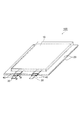
- FIG. 1 is a perspective view illustrating an all-solid-state battery that is an embodiment of a power storage device according to the present disclosure.
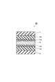
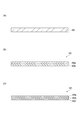
- FIG. 2 is a cross-sectional view schematically showing one embodiment of the exterior material.
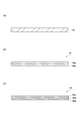
- 3A to 3C are cross-sectional views schematically showing the configuration of the inner layer.
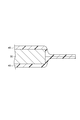
- FIG. 4 is a cross-sectional view taken along the line IV-IV shown in FIG. 1, and is a view schematically showing the configuration of the tab (resin film for terminal and metal terminal) of the all-solid-state battery.
- 5A to 5C are cross-sectional views schematically showing the configuration of the terminal resin film.
- FIG. 1 is a perspective view illustrating a schematic configuration of a power storage device according to the present embodiment.
- FIG. 1 illustrates an all-solid-state battery as an example of the power storage device 100, and the following description will be given.
- the power storage device having the structure illustrated in FIG. 1 is sometimes referred to as a battery pack or a battery cell.
- the power storage device 100 is an all-solid-state battery, and includes a power storage device main body 10, an exterior material 20, a pair of metal terminals 30 (current extraction terminals), and a terminal resin film 40 (tab sealant).
- the power storage device main body 10 is a battery main body that performs charging and discharging.
- the exterior member 20 is arranged so as to cover the surface of the power storage device main body 10 and to contact a part of the terminal resin film 40.
- FIG. 2 is a cross-sectional view illustrating an example of a cut surface of the exterior material 20.
- the exterior material 20 includes a base layer 11, a first adhesive layer 12a, a first corrosion prevention treatment layer 13a, and a barrier layer (metal foil layer) from the outside toward the inside (toward the power storage device body 10). 15, a second corrosion prevention treatment layer 13b, a second adhesive layer 12b, and an inner layer 18 in this order.
- the inner layer 18 contains polyethylene terephthalate (PET) or a copolymer thereof and has a melting peak temperature in the range of 160 to 280 ° C.
- PET polyethylene terephthalate
- the base material layer 11 has a melting peak temperature higher than the melting peak temperature of the inner layer 18.
- the inner layer 18 contains PET or a copolymer thereof and has a melting peak temperature in the range of 160 to 280 ° C., for example, the power storage device 100 (all solid state battery) used under a temperature condition of 100 to 150 ° C.
- the exterior material 20 can achieve the heat resistance required for the exterior material.
- the base material layer 11 has a melting peak temperature higher than the melting peak temperature of the inner layer 18, the appearance is deteriorated due to the melting of the base material layer 11 (outer layer) during heat sealing. Can be suppressed.
- the inner layer 18 and the base material layer 11 will be described.
- a commercially available crystalline PET film (melting peak temperature: about 255 ° C.) can be used.
- the melting peak temperature of the inner layer 18 may be adjusted within the above range according to the heat resistance required for the inner layer 18 (such as the operating temperature condition of the power storage device 100). For example, the crystallinity of the crystalline PET film is adjusted. Or non-stretched, a copolymer containing units of polyethylene terephthalate and units of other resins, or a PET film containing crystalline PET and amorphous PET may be used. . Alternatively, a polyester resin based on the PET component may be used as the material of the inner layer 18.
- Such a polyester resin has a structural unit derived from ethylene glycol and a structural unit derived from terephthalic acid, and other structural units.
- the dihydric alcohol component from which the structural unit of the polyester resin is derived include neopentyl glycol, 1,4-butadiol, diethylene glycol, and the like.
- the acid component from which the structural unit of the polyester resin is derived include isophthalic acid, adipic acid, sebacic acid, and the like. By adjusting the amounts of these structural units, the melting point of the polyester resin can be adjusted.
- the polyester-based resin based on the PET copolymer and the PET component is referred to as a PET-based resin.
- the melting peak temperature of the inner layer 18 is in the range of 160 to 280 ° C. as described above. If this temperature is lower than 160 ° C., the heat resistance of the inner layer 18 becomes insufficient, and if it exceeds 280 ° C., the temperature required for heat sealing becomes excessively high.
- the lower limit of the melting peak temperature of the inner layer 18 may be 175 ° C, 185 ° C, 195 ° C, 200 ° C, 215 ° C, 215 ° C, 225 ° C or 235 ° C.
- the upper limit of the melting peak temperature of the inner layer 18 may be 275 ° C, 268 ° C, 262 ° C, or 252 ° C.
- the inner layer 18 may have a single-layer structure or a multilayer structure. As shown in FIG. 3A, when the inner layer 18 has a single-layer structure, the inner layer 18 may be, for example, a crystalline PET film (melting peak temperature: about 255 ° C.) or a crystalline PET film. May be adjusted, the non-stretched material may be adjusted, or the melting peak temperature may be lowered to a range of, for example, 160 to 250 ° C. by using a PET resin. When a PET film having a reduced melting peak temperature is used as the inner layer 18, a crystalline PET film (melting peak temperature: about 255 ° C.) can be used as the base layer 11.
- a PET film having a reduced melting peak temperature is used as the inner layer 18
- a crystalline PET film (melting peak temperature: about 255 ° C.) can be used as the base layer 11.
- the thickness of the inner layer 18 is preferably 10 to 100 ⁇ m, and more preferably 20 to 80 ⁇ m.
- the thickness of the inner layer 18 is 10 ⁇ m or more, it is easy to secure sealing and insulating properties, and when it is 100 ⁇ m or less, cost can be reduced.
- the inner layer 18 may have a two-layer structure including a first layer 18a and a second layer 18b formed on a surface inside the first layer 18a.
- the first layer 18a preferably contains PET and / or PET-based resin and has a melting peak temperature of 170 to 280 ° C.
- the second layer 18b preferably contains PET and / or PET-based resin and has a lower melting peak temperature than the melting peak temperature of the first layer 18a.
- the melting peak temperature of the second layer 18b may be, for example, in the range of 160 to 270 ° C.
- Differences in melting peak temperature T B of the first and the melting peak temperature T A of the layer 18a a second layer 18b is a preferably at 10 ° C. or higher, more preferably 20 ⁇ 100 ° C. is there. When the temperature difference is 10 ° C. or more, more excellent sealing strength can be achieved.
- the thickness of the first layer 18a is preferably 5 to 500 ⁇ m, more preferably 20 to 200 ⁇ m. When the thickness of the first layer 18a is 5 ⁇ m or more, it is easy to secure insulation, and when it is 500 ⁇ m or less, cost can be reduced.
- the second layer 18b may contain a thermosetting resin instead of PET or PET-based resin, or may be made of PET or PET-based resin and thermosetting resin. It may include both.
- the thermosetting resin include polyimide resin, phenol resin, urea resin, melamine resin, unsaturated polyester resin, urethane resin, allyl resin, epoxy resin, furan resin and silicone resin. Of these, one type may be used alone, or two or more types may be used in combination.
- the thickness of the second layer 18b is preferably 5-500 ⁇ m, more preferably 20-200 ⁇ m. When the thickness of the second layer 18b is 5 ⁇ m or more, it is easy to secure sealing performance, and when it is 500 ⁇ m or less, cost reduction can be achieved.
- the inner layer 18 has a first layer 18a, a second layer 18b, and a surface of the first layer 18a opposite to the side on which the second layer 18b is formed. May have a three-layer structure having the third layer 18c formed on the third layer.
- the third layer 18c preferably contains PET and / or PET-based resin and has a lower melting peak temperature than the melting peak temperature of the first layer 18a.
- the melting peak temperature of the third layer 18c may be, for example, in the range of 160 to 270 ° C.
- Differences in melting peak temperature T C of the first and the melting peak temperature T A of the layer 18a third layer 18c (T A -T C) is a preferably at 10 ° C. or higher, more preferably 20 ⁇ 100 ° C. is there. When the temperature difference is 10 ° C. or more, more excellent sealing strength can be achieved.
- the third layer 18c may contain a thermosetting resin instead of PET or PET resin, or may be made of PET or PET resin and thermosetting resin. It may include both.
- the thermosetting resin include polyimide resin, phenol resin, urea resin, melamine resin, unsaturated polyester resin, urethane resin, allyl resin, epoxy resin, furan resin and silicone resin. Of these, one type may be used alone, or two or more types may be used in combination.
- the thickness of the third layer 18c is preferably 5 to 500 ⁇ m, and more preferably 20 to 200 ⁇ m. When the thickness of the third layer 18c is 5 ⁇ m or more, high sealing strength can be easily secured, and when it is 500 ⁇ m or less, cost reduction can be achieved.
- the above-described second layer 18b and third layer 18c may have the same configuration or different configurations.
- the inner layer 18 may include, for example, various additives (for example, a flame retardant, a slip agent, an antiblocking agent, an antioxidant, a light stabilizer, a tackifier, and the like).
- the base material layer 11 has a melting peak temperature higher than the melting peak temperature of the inner layer 18 as described above.
- the melting peak temperature of the inner layer 18 means the melting peak temperature of the layer having the highest melting peak temperature (for example, the first layer 18a).
- the melting peak temperature of the base material layer 11 is preferably 290 ° C. or higher, and more preferably 290 to 350 ° C.
- the resin film that can be used as the base material layer 11 and have a melting peak temperature in the above range include a nylon film, a PET film, a polyamide film, and a polyphenylene sulfide film (PPS film).
- the base layer 11 a commercially available film may be used, or the base layer 11 may be formed by coating (application and drying of a coating liquid).
- the base layer 11 may have a single-layer structure or a multi-layer structure, and may be formed by applying a thermosetting resin.
- the base material layer 11 may include, for example, various additives (for example, a flame retardant, a slip agent, an anti-blocking agent, an antioxidant, a light stabilizer, a tackifier, and the like).
- Differences in melting peak temperature T 18 of the melting peak temperature T 11 and the inner layer 18 of the substrate layer 11 is preferably at 20 ° C. or higher, more preferably 40 ⁇ 100 ° C..
- the thickness of the base material layer 11 is preferably 5 to 50 ⁇ m, and more preferably 12 to 30 ⁇ m.
- first adhesive layer 12a the first corrosion prevention treatment layer 13a, the barrier layer (metal foil layer) 15, the second corrosion prevention treatment layer 13b, and the second adhesion layer 12b will be described. These layers have the same or higher heat resistance as the inner layer 18 and the base layer 11 described above.
- the adhesive layers 12a and 12b only need to have sufficient heat resistance.
- known adhesives such as a general adhesive for dry lamination, an acid-modified heat-fusible resin, and a thermosetting adhesive can be used.
- An adhesive can be appropriately selected and used.
- the thermosetting adhesive include a polyester urethane adhesive and an epoxy adhesive. From the viewpoint of heat resistance, each of the adhesive layers 12a and 12b is preferably made of a cured product of a thermosetting adhesive.
- the barrier layer 15 is a metal layer having conductivity.
- a material of the barrier layer 15 for example, aluminum, stainless steel, or the like can be exemplified. However, aluminum is preferable in terms of cost, weight (density), and the like.
- the corrosion prevention treatment layers 13a and 13b are for protecting the barrier layer 15.
- a layer containing a rare earth element oxide (for example, cerium oxide) and phosphoric acid or phosphate may be mentioned.
- FIG. 4 is a cross-sectional view of the terminal resin film and the metal terminal shown in FIG. 1 taken along the line IV-IV.
- One of the pair of (two in FIG. 1) metal terminals 30, 30 is electrically connected to the positive electrode of the power storage device main body 10, and the other metal terminal 30 is connected to the power storage device. It is electrically connected to the negative electrode of the main body 10.
- the pair of metal terminals 30 extends from the power storage device main body 10 to the outside of the exterior material 20.
- the shape of the pair of metal terminals 30, 30 can be, for example, a flat plate shape.
- a metal can be used as the material of the metal terminal 30.
- the metal used as the material of the metal terminal 30 may be determined in consideration of the structure of the power storage device main body 10, the material of each component of the power storage device main body 10, and the like. For example, when power storage device 100 is an all-solid-state battery, it is preferable to use aluminum as the material of metal terminal 30 connected to the positive electrode of power storage device main body 10. As a material of the metal terminal 30 connected to the negative electrode of the power storage device main body 10, it is preferable to use copper having a nickel plating layer formed on the surface or nickel.
- the thickness of the metal terminal 30 depends on the size and capacity of the all-solid-state battery. When the all-solid-state battery is small, the thickness of the metal terminal 30 may be, for example, 50 ⁇ m or more. In the case of a large all-solid-state battery for power storage and in-vehicle use, the thickness of the metal terminal 30 can be appropriately set within a range of, for example, 100 to 500 ⁇ m.
- the terminal resin film 40 is arranged so as to cover a part of the outer peripheral surface of the metal terminal 30.
- the terminal resin film 40 has the same or higher heat resistance as the inner layer 18 and the base layer 11 described above. Note that, when the inner layer 18 of the exterior material 20 can sufficiently secure the sealing property and the insulating property of the power storage device 100, the terminal resin film 40 may not be used.
- the terminal resin film 40 is made of a resin composition having adhesion to the metal terminal 30, and the resin composition contains at least one of a thermosetting resin and a thermoplastic resin having a melting peak temperature of 160 ° C. or higher, and It is preferable not to contain a thermoplastic resin having a melting peak temperature of less than 160 ° C. According to the terminal resin film 40 having such a configuration, even if the power storage device is used under a temperature condition of, for example, 100 to 150 ° C., the temperature of the metal terminal 30 reaches, for example, 100 to 150 ° C. However, the power storage device 100 can be sufficiently sealed.
- the resin composition contains at least one of a thermosetting resin and a thermoplastic resin having a melting peak temperature (melting point) of 200 ° C. or more, and does not contain a thermoplastic resin having a melting peak temperature of less than 200 ° C. You may.
- thermosetting resin used for the terminal resin film 40 is selected from the group consisting of polyimide resin, phenol resin, urea resin, melamine resin, unsaturated polyester resin, urethane resin, allyl resin, epoxy resin, furan resin and silicone resin. At least one kind of resin to be used. These thermosetting resins have excellent adhesion to metal materials (for example, aluminum and nickel) forming the surface of the metal terminal 30 and also have excellent heat resistance.
- thermoplastic resin used for the terminal resin film 40 examples include PET, the above-mentioned PET resin, nylon, polyvinyl alcohol resin, polyvinylidene chloride, polyamide resin, polybutylene terephthalate resin, polyphenylene sulfide, polyetherimide, polysulfone, and fluorine. At least one resin selected from the group consisting of resin, polyamideimide and acetyl cellulose may be employed. These thermoplastic resins have excellent adhesion to metal materials (for example, aluminum and nickel) constituting the surface of the metal terminal 30, and also have excellent heat resistance.
- metal materials for example, aluminum and nickel
- the terminal resin film 40 may have a single-layer structure or a multilayer structure.
- the resin composition forming the terminal resin film 40 is selected from the group consisting of PET, polyphenylene sulfide, urethane resin, and epoxy resin. It is preferably one kind of thermosetting resin selected from the group consisting of one kind of thermoplastic resin and / or urethane resin and epoxy resin.
- the terminal resin film 40 may be made of PET and / or PET resin having a melting peak temperature of 160 to 270 ° C. or polyphenylene sulfide (PPS) having a melting peak temperature of 260 to 300 ° C. ) And a second layer made of a thermosetting resin or a thermoplastic resin having a melting peak temperature of 160 to 270 ° C. formed on the surface of the first layer 40 a facing the metal terminal 30. (See FIG. 5B).
- PET and / or PET-based resin or PPS having a sufficiently high melting peak temperature as the resin constituting the first layer 40a, the first layer 40a does not melt at the time of heat sealing. Excellent insulation can be achieved.
- the melting peak temperature of the resin (PET and / or PET-based resin) constituting the first layer 40a may be 210 ° C. or higher.
- the melting peak temperature of the resin (PET and / or PET-based resin) constituting the second layer 40b may be 200 ° C. or higher.
- Differences in melting peak temperature S B of the first melting peak temperature of the layer 40a S A and the second layer 40b (S A -S B) is a preferably at 10 ° C. or higher, more preferably 20 ⁇ 100 ° C. is there. When this temperature difference is 10 ° C. or more, excellent insulation of the metal terminal 30 can be achieved.
- the thickness of the first layer 40a is preferably 5 to 500 ⁇ m, more preferably 20 to 200 ⁇ m. When the thickness of the first layer 40a is 5 ⁇ m or more, insulation can be easily ensured, and when it is 500 ⁇ m or less, cost can be reduced.
- the thickness of the second layer 40b is preferably from 5 to 500 ⁇ m, more preferably from 20 to 200 ⁇ m. When the thickness of the second layer 40b is 5 ⁇ m or more, it is easy to secure sealing performance, and when it is 500 ⁇ m or less, cost reduction can be achieved.
- the terminal resin film 40 When the terminal resin film 40 has a multilayer structure including the first and second layers 40a and 40b, the terminal resin film 40 is formed on the surface of the first layer 40a opposite to the side on which the second layer 40b is formed.
- a third layer 40c may be further provided (see FIG. 5C).
- the third layer 40c can be made of a thermosetting resin or a thermoplastic resin having a peak melting temperature of 160 to 270 ° C.
- the first layer 40a is made of a thermosetting resin
- a thermosetting resin having higher fluidity than the thermosetting resin forming the first layer 40a As the second layer 40b, excellent adhesion to the metal terminal 30 can be achieved by the second layer 40b during heat sealing.
- a thermosetting resin having higher fluidity than the thermosetting resin forming the first layer 40a may be employed as the third layer 40c. With such a structure, the power storage device 100 with more excellent sealing performance can be obtained.
- the thickness of the third layer 40c is preferably 5 to 500 ⁇ m, and more preferably 20 to 200 ⁇ m. When the thickness of the third layer 40c is 5 ⁇ m or more, it is easy to secure sealing performance, and when it is 500 ⁇ m or less, cost reduction can be achieved.
- an electric solid-state battery is illustrated as the power storage device to which the exterior material 20 is applied, but the exterior material 20 may be applied to another power storage device (for example, a lithium ion battery).
- Example 1 A high heat-resistant polyamide film (thickness: 25 ⁇ m) having a melting peak temperature of 300 ° C. was prepared as a substrate layer. An aluminum foil (thickness: 40 ⁇ m) was prepared as a metal foil layer. As the inner layer, a PET film (thickness: 75 ⁇ m, single layer structure) having a melting peak temperature of 255 ° C. was prepared. The base material layer and the metal foil layer are bonded with a thermosetting adhesive (polyester urethane), and the metal foil layer and the inner layer are bonded with the same adhesive to obtain the exterior material according to the present embodiment. Was.
- a thermosetting adhesive polyyester urethane
- Example 2 Except for using a PPS film (thickness: 100 ⁇ m) having a melting peak temperature of 290 ° C. instead of the high heat-resistant polyamide film as the base material layer, the exterior material according to this example was prepared in the same manner as in Example 1. Obtained.
- Example 3 A packaging material according to this example was obtained in the same manner as in Example 1, except that an epoxy-based thermosetting adhesive was used instead of the polyester-urethane-based thermosetting adhesive.
- Example 4 Except for using a polyester-based adhesive (melting peak temperature: 85 ° C.) instead of using a polyester urethane-based thermosetting adhesive, the exterior material according to the present example was prepared in the same manner as in Example 1. Obtained.
- a base material layer As a base material layer, a nylon film (thickness: 25 ⁇ m) having a melting peak temperature of 225 ° C. was prepared. An aluminum foil (thickness: 40 ⁇ m) was prepared as a metal foil layer. As the inner layer, a polypropylene-based film (thickness: 75 ⁇ m, single layer structure) having a melting peak temperature of 140 ° C. was prepared. The base material layer and the metal foil layer are bonded together with a polypropylene-based adhesive (melting peak temperature: 85 ° C.), and the metal foil layer and the inner layer are bonded together with the same adhesive. Got.
- Comparative Example 2 Except for using a PET film (thickness: 25 ⁇ m) having a melting peak temperature of 255 ° C. instead of the high heat resistant polyamide film as the base material layer, the exterior material according to this comparative example was prepared in the same manner as in Example 1. Obtained.
- an exterior material that is useful for manufacturing a power storage device having an excellent appearance and has excellent heat resistance and a power storage device using the same are provided.
- SYMBOLS 10 Power storage device main body, 11 ... Base material layer, 12a ... First adhesive layer, 15 ... Barrier layer (metal foil layer), 12b ... Second adhesive layer, 18 ... Inner layer, 18a ... First layer, 18b ... second layer, 18c ... third layer, 20 ... exterior material, 30 ... metal terminal (current extraction terminal), 40 ... terminal resin film, 100 ... power storage device
Landscapes
- Chemical & Material Sciences (AREA)
- Chemical Kinetics & Catalysis (AREA)
- Electrochemistry (AREA)
- General Chemical & Material Sciences (AREA)
- Engineering & Computer Science (AREA)
- Manufacturing & Machinery (AREA)
- Power Engineering (AREA)
- Inorganic Chemistry (AREA)
- Microelectronics & Electronic Packaging (AREA)
- Materials Engineering (AREA)
- General Physics & Mathematics (AREA)
- Condensed Matter Physics & Semiconductors (AREA)
- Physics & Mathematics (AREA)
- Sealing Battery Cases Or Jackets (AREA)
- Electric Double-Layer Capacitors Or The Like (AREA)
- Secondary Cells (AREA)
Abstract
Description
図1は、本実施形態に係る蓄電装置の概略構成を示す斜視図である。図1では、蓄電装置100の一例として、全固体電池を例に挙げて図示し、以下の説明を行う。なお、図1に示す構成の蓄電装置は、電池パック又は電池セルと呼ばれることがある。
図2は、外装材20の切断面の一例を示す断面図である。外装材20は、外側から内側(蓄電装置本体10側)に向けて、基材層11と、第一の接着層12aと、第一の腐食防止処理層13aと、バリア層(金属箔層)15と、第二の腐食防止処理層13bと、第二の接着層12bと、内層18とをこの順序で備える多層構造を有する。そして、内層18は、ポリエチレンテレフタラート(PET)又はその共重合体を含み且つ160~280℃の範囲に融解ピーク温度を有する。基材層11は、内層18の融解ピーク温度よりも高い融解ピーク温度を有する。
図4は、図1に示す端子用樹脂フィルム及び金属端子のIV-IV線方向の断面図である。一対(図1の場合、2つ)の金属端子30,30のうち、一方の金属端子30は、蓄電装置本体10の正極と電気的に接続されており、他方の金属端子30は、蓄電装置本体10の負極と電気的に接続されている。一対の金属端子30,30は、蓄電装置本体10から外装材20の外部まで延びている。一対の金属端子30,30の形状は、例えば、平板形状とすることができる。
図4に示すように、端子用樹脂フィルム40は、金属端子30の一部の外周面を覆うように配置されている。金属端子30と外装材20との間に端子用樹脂フィルム40を配置されることで、蓄電装置100の密封性及び絶縁性をより一層高度に達成することができる。端子用樹脂フィルム40は、上述の内層18及び基材層11と同等又はこれを越える耐熱性を有する。なお、外装材20の内層18によって蓄電装置100の密封性及び絶縁性を十分に確保できる場合は、端子用樹脂フィルム40は使用しなくてもよい。
(実施例1)
基材層として、融解ピーク温度が300℃の高耐熱ポリアミドフィルム(厚さ:25μm)を準備した。金属箔層として、アルミニウム箔(厚さ:40μm)を準備した。内層として、融解ピーク温度が255℃のPETフィルム(厚さ:75μm、単層構造)を準備した。基材層と金属箔層とを熱硬化性接着剤(ポリエステルウレタン系)で貼り合わせるとともに、これと同じ接着剤で金属箔層と内層とを貼り合わせることによって本実施例に係る外装材を得た。
基材層として、高耐熱ポリアミドフィルムの代わりに融解ピーク温度が290℃のPPSフィルム(厚さ:100μm)を使用したことの他は、実施例1と同様にして本実施例に係る外装材を得た。
ポリエステルウレタン系の熱硬化性接着剤を使用する代わりに、エポキシ系の熱硬化性接着剤を使用したことの他は、実施例1と同様にして本実施例に係る外装材を得た。
ポリエステルウレタン系の熱硬化性接着剤を使用する代わりに、ポリプロピレン系接着剤(融解ピーク温度:85℃)を使用したことの他は、実施例1と同様にして本実施例に係る外装材を得た。
基材層として、融解ピーク温度が225℃のナイロンフィルム(厚さ:25μm)を準備した。金属箔層として、アルミニウム箔(厚さ:40μm)を準備した。内層として、融解ピーク温度が140℃のポリプロピレン系フィルム(厚さ:75μm、単層構造)を準備した。基材層と金属箔層とをポリプロピレン系接着剤(融解ピーク温度:85℃)で貼り合わせるとともに、これと同じ接着剤で金属箔層と内層とを貼り合わせることによって本比較例に係る外装材を得た。
基材層として、高耐熱ポリアミドフィルムの代わりに融解ピーク温度が255℃のPETフィルム(厚さ:25μm)を使用したことの他は、実施例1と同様にして本比較例に係る外装材を得た。
各例で作製した外装材を、60mm×80mmのサイズに2枚切り取り、短辺同士を合わせ、280℃、面圧0.5MPa、時間10秒の条件で短辺をヒートシールした。ヒートシールした部分を15mm幅に切り取ることによって測定用試料を得た。各試料について以下の条件で高温条件下でのシール強度を測定した。
測定装置:INSTRON社製万能材料試験機
測定温度:150℃
測定タイミング:試料を150℃の温度条件下に投入してから5経過後に測定を開始した。
測定方法:JIS K6854-2:1990「接着剤-はく離接着強さ試験-第2部:180度はく離」に記載の方法に準拠(剥離方法:T字、剥離速度50mm/分)して剥離強度(ヒートシール強さ)を測定した。評価は以下の基準に従って行った。表1及び表2に結果を示す。
「A」:剥離強度が10N/15mm以上
「B」:剥離強度が10N/15mm未満
シール強度の評価後のサンプルのヒートシール部を目視で確認することによって外観の評価を行った。評価は以下の基準に従って行い、評価Cを不適とした。表1に結果を示す。
「A」:シール直後に基材層の外観に融解が認められず、また変色も認められない。
「B」:シール直後に基材層の外観に融解が認められないものの、変色が認められる。
「C」:シール直後に基材層の外観に融解が認められる。


Claims (14)
- 蓄電装置用外装材であって、
基材層と、
第一の接着層と、
金属箔層と、
第二の接着層と、
ポリエステル系樹脂を含む内層と、
をこの順で備える積層構造を有し、
前記内層は、160~280℃の範囲に、示差走査熱量計により測定される融解時の融解ピーク温度を有し、
前記基材層は、前記内層の融解ピーク温度よりも高い融解ピーク温度を有する、外装材。 - 全固体電池用である、請求項1に記載の外装材。
- 前記内層が単層構造である、請求項1又は2に記載の外装材。
- 前記内層が多層構造を有し、
ポリエステル系樹脂を含み且つ融解ピーク温度が170~280℃である第一の層と、
前記第一の層の内側の表面上に形成されており、熱硬化性樹脂を含む第二の層と、
を有する多層構造である、請求項1又は2に記載の外装材。 - 前記内層が多層構造を有し、
ポリエステル系樹脂を含み且つ融解ピーク温度が170~280℃である第一の層と、
前記第一の層の内側の表面上に形成されており、ポリエステル系樹脂を含む第二の層と、
を有する多層構造であり、
前記第二の層は、160~270℃の範囲であり且つ前記第一の層の融解ピーク温度よりも低い融解ピーク温度を有する、請求項1又は2に記載の外装材。 - 前記第一の層の融点TAと前記第二の層の融点TBとの差TA-TBが10℃以上である、請求項5に記載の外装材。
- 前記第一の層における前記第二の層が形成されている側と反対側の表面に形成された第三の層を更に備え、
前記第三の層は、ポリエステル系樹脂を含み、160~270℃の範囲であり且つ前記第一の層の融解ピーク温度よりも低い融解ピーク温度を有する、請求項4~6のいずれか一項に記載の外装材。 - 前記第一の層における前記第二の層が形成されている側と反対側の表面に形成された第三の層を更に備え、
前記第三の層は、熱硬化性樹脂を含む、請求項4~6のいずれか一項に記載の外装材。 - 前記ポリエステル系樹脂がポリエチレンテレフタラート及びポリエチレンテレフタラート系樹脂の少なくとも一方である、請求項1~8のいずれか一項に記載の外装材。
- 前記ポリエチレンテレフタラート系樹脂は、エチレングリコールに由来する構造単位及びテレフタル酸に由来する構造単位と、その他の構造単位とを含み、
前記その他の構造単位の由来となる二価アルコール成分がネオペンチルグリコール、1,4-ブタジオール及びジエチレングリコールからなる群から選ばれる少なくとも一種である、請求項9に記載の外装材。 - 前記ポリエチレンテレフタラート系樹脂は、エチレングリコールに由来する構造単位及びテレフタル酸に由来する構造単位と、その他の構造単位とを含み、
前記その他の構造単位の由来となる酸成分がイソフタル酸、アジピン酸及びセバシン酸からなる群から選ばれる少なくとも一種である、請求項9又は10に記載の外装材。 - 前記第一の接着層及び前記第二の接着層が熱硬化性接着剤の硬化物からなる、請求項1~11のいずれか一項に記載の外装材。
- 蓄電装置本体と、
前記蓄電装置本体から延在する電流取出し端子と、
前記電流取出し端子を挟持し且つ前記蓄電装置本体を収容する、請求項1~12のいずれか一項に記載の外装材と、
を備える蓄電装置。 - 全固体電池である、請求項13に記載の蓄電装置。
Priority Applications (5)
| Application Number | Priority Date | Filing Date | Title |
|---|---|---|---|
| CN201980041950.XA CN112335098A (zh) | 2018-06-27 | 2019-06-25 | 蓄电装置用封装材料以及使用了该封装材料的蓄电装置 |
| JP2020527554A JP7318647B2 (ja) | 2018-06-27 | 2019-06-25 | 蓄電装置用外装材及びこれを用いた蓄電装置 |
| KR1020207029531A KR20210021942A (ko) | 2018-06-27 | 2019-06-25 | 축전 장치용 외장재 및 이것을 사용한 축전 장치 |
| EP19825856.8A EP3817081A4 (en) | 2018-06-27 | 2019-06-25 | OUTSIDE PACKAGING MATERIAL FOR ELECTRICITY STORAGE DEVICES AND ELECTRICITY STORAGE DEVICE THEREFORE |
| US17/093,514 US20210057683A1 (en) | 2018-06-27 | 2020-11-09 | Power storage device packaging material and power storage device using the packaging material |
Applications Claiming Priority (2)
| Application Number | Priority Date | Filing Date | Title |
|---|---|---|---|
| JP2018-121795 | 2018-06-27 | ||
| JP2018121795 | 2018-06-27 |
Related Child Applications (1)
| Application Number | Title | Priority Date | Filing Date |
|---|---|---|---|
| US17/093,514 Continuation US20210057683A1 (en) | 2018-06-27 | 2020-11-09 | Power storage device packaging material and power storage device using the packaging material |
Publications (1)
| Publication Number | Publication Date |
|---|---|
| WO2020004413A1 true WO2020004413A1 (ja) | 2020-01-02 |
Family
ID=68986719
Family Applications (1)
| Application Number | Title | Priority Date | Filing Date |
|---|---|---|---|
| PCT/JP2019/025223 Ceased WO2020004413A1 (ja) | 2018-06-27 | 2019-06-25 | 蓄電装置用外装材及びこれを用いた蓄電装置 |
Country Status (6)
| Country | Link |
|---|---|
| US (1) | US20210057683A1 (ja) |
| EP (1) | EP3817081A4 (ja) |
| JP (1) | JP7318647B2 (ja) |
| KR (1) | KR20210021942A (ja) |
| CN (1) | CN112335098A (ja) |
| WO (1) | WO2020004413A1 (ja) |
Cited By (7)
| Publication number | Priority date | Publication date | Assignee | Title |
|---|---|---|---|---|
| JPWO2020004412A1 (ja) * | 2018-06-27 | 2021-08-02 | 凸版印刷株式会社 | 端子用樹脂フィルム及びこれを用いた蓄電装置 |
| JP2022139580A (ja) * | 2021-03-12 | 2022-09-26 | 双葉電子工業株式会社 | タブリード、非水電解質デバイス及びタブリードの製造方法 |
| WO2023042883A1 (ja) * | 2021-09-15 | 2023-03-23 | 大日本印刷株式会社 | 蓄電デバイス用外装材、その製造方法、フィルム、及び蓄電デバイス |
| EP3965215A4 (en) * | 2020-06-30 | 2023-06-21 | Ningde Amperex Technology Limited | SEPARATOR FOR ELECTROCHEMICAL EQUIPMENT, ELECTROCHEMICAL EQUIPMENT AND ELECTRONIC EQUIPMENT |
| JP2025020468A (ja) * | 2020-04-13 | 2025-02-12 | Toppanホールディングス株式会社 | 全固体電池用外装およびこれを用いた全固体電池 |
| EP4120415A4 (en) * | 2020-03-12 | 2025-02-19 | Dai Nippon Printing Co., Ltd. | Outer package material for all-solid-state batteries, method for producing same and all-solid-state battery |
| JP7731659B2 (ja) | 2020-04-06 | 2025-09-01 | Toppanホールディングス株式会社 | 蓄電デバイス用外装材 |
Families Citing this family (2)
| Publication number | Priority date | Publication date | Assignee | Title |
|---|---|---|---|---|
| KR102626933B1 (ko) * | 2021-06-10 | 2024-01-22 | 율촌화학 주식회사 | 계면 박리 조절을 통해 가스배출이 용이한 셀 파우치용 실란트 필름, 이를 포함하는 셀 파우치 및 그 제조 방법 |
| WO2022264601A1 (ja) * | 2021-06-17 | 2022-12-22 | ビークルエナジージャパン株式会社 | 固体電解質電池、固体電解質電池の製造方法、及び輸送機器 |
Citations (12)
| Publication number | Priority date | Publication date | Assignee | Title |
|---|---|---|---|---|
| JPH06322085A (ja) | 1993-05-17 | 1994-11-22 | Mitsubishi Kasei Corp | シーラント用共重合ポリエステル |
| WO1998042036A1 (en) | 1997-03-19 | 1998-09-24 | Asahi Kasei Kogyo Kabushiki Kaisha | Nonaqueous thin battery |
| JPH11213965A (ja) | 1998-01-23 | 1999-08-06 | Asahi Chem Ind Co Ltd | 電池用外装体及び電池 |
| JPH11312514A (ja) * | 1998-02-24 | 1999-11-09 | Sony Corp | リチウムイオン二次電池に用いるリード、リード用リボン、リチウムイオン二次電池、およびリチウムイオン二次電池の容器の封じ方法 |
| JP2013101765A (ja) | 2011-11-07 | 2013-05-23 | Toppan Printing Co Ltd | 蓄電デバイス用外装材 |
| WO2014123164A1 (ja) * | 2013-02-06 | 2014-08-14 | 大日本印刷株式会社 | 電池用包装材料 |
| US20150221902A1 (en) | 2012-09-26 | 2015-08-06 | Sanyo Electric Co., Ltd. | Gasket for a secondary battery and a secondary battery |
| JP2016072212A (ja) | 2014-09-30 | 2016-05-09 | 大日本印刷株式会社 | 電池用包装材料 |
| JP2018032616A (ja) * | 2016-08-17 | 2018-03-01 | 昭和電工パッケージング株式会社 | 蓄電デバイス用外装材及び蓄電デバイス |
| JP2018045163A (ja) | 2016-09-16 | 2018-03-22 | 株式会社ユポ・コーポレーション | 電子写真用記録用紙およびそれを用いた記録物 |
| JP2018092885A (ja) * | 2016-11-25 | 2018-06-14 | 昭和電工株式会社 | リチウムイオン二次電池、リチウムイオン二次電池の製造方法 |
| JP2018121795A (ja) | 2017-01-31 | 2018-08-09 | 株式会社大一商会 | 遊技機 |
Family Cites Families (6)
| Publication number | Priority date | Publication date | Assignee | Title |
|---|---|---|---|---|
| DE60031523T2 (de) * | 1999-09-10 | 2007-06-06 | Ishida Co., Ltd. | Beutel für nahrungsmittel, verfahren zum verpacken und verwendung eines mehrschichtfilms für beutel |
| TW504851B (en) * | 2000-02-04 | 2002-10-01 | Alcan Technology & Amp Man Ltd | Battery packaging |
| US8828591B2 (en) * | 2006-03-02 | 2014-09-09 | Sony Corporation | External packaging material for battery device, nonaqueous electrolyte secondary battery using the same, and battery pack |
| JP6146953B2 (ja) * | 2012-01-31 | 2017-06-14 | 昭和電工パッケージング株式会社 | 電池用外装材およびリチウム二次電池 |
| JPWO2014200087A1 (ja) * | 2013-06-14 | 2017-02-23 | 凸版印刷株式会社 | 樹脂フィルム、金属端子部材、及び二次電池 |
| JP6686634B2 (ja) * | 2015-03-30 | 2020-04-22 | 大日本印刷株式会社 | 電池用包装材料、その製造方法及び電池 |
-
2019
- 2019-06-25 WO PCT/JP2019/025223 patent/WO2020004413A1/ja not_active Ceased
- 2019-06-25 EP EP19825856.8A patent/EP3817081A4/en active Pending
- 2019-06-25 JP JP2020527554A patent/JP7318647B2/ja active Active
- 2019-06-25 CN CN201980041950.XA patent/CN112335098A/zh active Pending
- 2019-06-25 KR KR1020207029531A patent/KR20210021942A/ko not_active Ceased
-
2020
- 2020-11-09 US US17/093,514 patent/US20210057683A1/en active Pending
Patent Citations (13)
| Publication number | Priority date | Publication date | Assignee | Title |
|---|---|---|---|---|
| JPH06322085A (ja) | 1993-05-17 | 1994-11-22 | Mitsubishi Kasei Corp | シーラント用共重合ポリエステル |
| WO1998042036A1 (en) | 1997-03-19 | 1998-09-24 | Asahi Kasei Kogyo Kabushiki Kaisha | Nonaqueous thin battery |
| US6461757B1 (en) | 1997-03-19 | 2002-10-08 | Asahi Kasei Kogyo Kabushiki Kaisha | Non-aqueous battery of a thin configuration |
| JPH11213965A (ja) | 1998-01-23 | 1999-08-06 | Asahi Chem Ind Co Ltd | 電池用外装体及び電池 |
| JPH11312514A (ja) * | 1998-02-24 | 1999-11-09 | Sony Corp | リチウムイオン二次電池に用いるリード、リード用リボン、リチウムイオン二次電池、およびリチウムイオン二次電池の容器の封じ方法 |
| JP2013101765A (ja) | 2011-11-07 | 2013-05-23 | Toppan Printing Co Ltd | 蓄電デバイス用外装材 |
| US20150221902A1 (en) | 2012-09-26 | 2015-08-06 | Sanyo Electric Co., Ltd. | Gasket for a secondary battery and a secondary battery |
| WO2014123164A1 (ja) * | 2013-02-06 | 2014-08-14 | 大日本印刷株式会社 | 電池用包装材料 |
| JP2016072212A (ja) | 2014-09-30 | 2016-05-09 | 大日本印刷株式会社 | 電池用包装材料 |
| JP2018032616A (ja) * | 2016-08-17 | 2018-03-01 | 昭和電工パッケージング株式会社 | 蓄電デバイス用外装材及び蓄電デバイス |
| JP2018045163A (ja) | 2016-09-16 | 2018-03-22 | 株式会社ユポ・コーポレーション | 電子写真用記録用紙およびそれを用いた記録物 |
| JP2018092885A (ja) * | 2016-11-25 | 2018-06-14 | 昭和電工株式会社 | リチウムイオン二次電池、リチウムイオン二次電池の製造方法 |
| JP2018121795A (ja) | 2017-01-31 | 2018-08-09 | 株式会社大一商会 | 遊技機 |
Non-Patent Citations (2)
| Title |
|---|
| "Adhesives -Determination of peel strength of bonded assemblies- Part 2: 180° peeling", JIS K, vol. 6854, no. 2, pages 1990 |
| See also references of EP3817081A4 |
Cited By (11)
| Publication number | Priority date | Publication date | Assignee | Title |
|---|---|---|---|---|
| JPWO2020004412A1 (ja) * | 2018-06-27 | 2021-08-02 | 凸版印刷株式会社 | 端子用樹脂フィルム及びこれを用いた蓄電装置 |
| EP3817083A4 (en) * | 2018-06-27 | 2021-11-17 | Toppan Printing Co., Ltd. | RESIN FILM FOR TERMINAL DEVICE AND ENERGY STORAGE DEVICE WITH RESIN FILM FOR TERMINAL DEVICE |
| JP7415921B2 (ja) | 2018-06-27 | 2024-01-17 | Toppanホールディングス株式会社 | 端子用樹脂フィルム及びこれを用いた蓄電装置 |
| EP4120415A4 (en) * | 2020-03-12 | 2025-02-19 | Dai Nippon Printing Co., Ltd. | Outer package material for all-solid-state batteries, method for producing same and all-solid-state battery |
| US12506197B2 (en) | 2020-03-12 | 2025-12-23 | Dai Nippon Printing Co., Ltd. | Outer package material for all-solid-state batteries, method for producing same and all-solid-state battery |
| JP7731659B2 (ja) | 2020-04-06 | 2025-09-01 | Toppanホールディングス株式会社 | 蓄電デバイス用外装材 |
| JP2025020468A (ja) * | 2020-04-13 | 2025-02-12 | Toppanホールディングス株式会社 | 全固体電池用外装およびこれを用いた全固体電池 |
| JP7782653B2 (ja) | 2020-04-13 | 2025-12-09 | Toppanホールディングス株式会社 | 全固体電池用外装およびこれを用いた全固体電池 |
| EP3965215A4 (en) * | 2020-06-30 | 2023-06-21 | Ningde Amperex Technology Limited | SEPARATOR FOR ELECTROCHEMICAL EQUIPMENT, ELECTROCHEMICAL EQUIPMENT AND ELECTRONIC EQUIPMENT |
| JP2022139580A (ja) * | 2021-03-12 | 2022-09-26 | 双葉電子工業株式会社 | タブリード、非水電解質デバイス及びタブリードの製造方法 |
| WO2023042883A1 (ja) * | 2021-09-15 | 2023-03-23 | 大日本印刷株式会社 | 蓄電デバイス用外装材、その製造方法、フィルム、及び蓄電デバイス |
Also Published As
| Publication number | Publication date |
|---|---|
| JP7318647B2 (ja) | 2023-08-01 |
| US20210057683A1 (en) | 2021-02-25 |
| JPWO2020004413A1 (ja) | 2021-08-05 |
| EP3817081A1 (en) | 2021-05-05 |
| EP3817081A4 (en) | 2021-08-18 |
| KR20210021942A (ko) | 2021-03-02 |
| CN112335098A (zh) | 2021-02-05 |
Similar Documents
| Publication | Publication Date | Title |
|---|---|---|
| JP7415921B2 (ja) | 端子用樹脂フィルム及びこれを用いた蓄電装置 | |
| JP7318647B2 (ja) | 蓄電装置用外装材及びこれを用いた蓄電装置 | |
| TWI581959B (zh) | 電池用外裝材及鋰二次電池 | |
| CN205752283U (zh) | 蓄电器件用外装体及蓄电器件 | |
| JP2020077646A (ja) | 蓄電装置用外装材、及びそれを用いた蓄電装置 | |
| KR102507154B1 (ko) | 이차 전지용 단자 피복 수지 필름, 이차 전지용 탭 부재, 및 이차 전지 | |
| JP5169112B2 (ja) | 扁平型電気化学セル金属端子部密封用接着性シート | |
| CN103855332B (zh) | 电化学元件用外装体 | |
| CN105552250B (zh) | 蓄电设备用外包装材料及蓄电设备 | |
| JP5720132B2 (ja) | 二次電池用金属端子被覆樹脂フィルム | |
| JP6738189B2 (ja) | 蓄電デバイス用外装材及び蓄電デバイス | |
| TW201503468A (zh) | 樹脂薄膜、金屬端子構件、及二次電池 | |
| JP2003007261A (ja) | 電池用包装材料 | |
| JP2026012902A (ja) | 端子用樹脂フィルム、及びそれを用いた蓄電デバイス | |
| KR20090092108A (ko) | 이차전지 패키지용 라미네이트 시트 및 이를 포함하는이차전지 | |
| JP2015201387A (ja) | 二次電池用外装材、二次電池、及び二次電池の製造方法 | |
| JP6221594B2 (ja) | 電池用外装体及びこれを用いた電池 | |
| KR102863082B1 (ko) | 파우치 필름 적층체, 이의 제조 방법 및 파우치형 이차 전지 | |
| JP7721949B2 (ja) | 端子用樹脂フィルム、及びそれを用いた蓄電デバイス | |
| CN114597600B (zh) | 层压式电池 | |
| JP6331316B2 (ja) | 二次電池用外装材および二次電池 |
Legal Events
| Date | Code | Title | Description |
|---|---|---|---|
| 121 | Ep: the epo has been informed by wipo that ep was designated in this application |
Ref document number: 19825856 Country of ref document: EP Kind code of ref document: A1 |
|
| ENP | Entry into the national phase |
Ref document number: 2020527554 Country of ref document: JP Kind code of ref document: A |
|
| NENP | Non-entry into the national phase |
Ref country code: DE |
|
| ENP | Entry into the national phase |
Ref document number: 2019825856 Country of ref document: EP Effective date: 20210127 |
|
| WWR | Wipo information: refused in national office |
Ref document number: 1020207029531 Country of ref document: KR |