WO2020004507A1 - Dispositif de modélisation en trois dimensions - Google Patents
Dispositif de modélisation en trois dimensions Download PDFInfo
- Publication number
- WO2020004507A1 WO2020004507A1 PCT/JP2019/025482 JP2019025482W WO2020004507A1 WO 2020004507 A1 WO2020004507 A1 WO 2020004507A1 JP 2019025482 W JP2019025482 W JP 2019025482W WO 2020004507 A1 WO2020004507 A1 WO 2020004507A1
- Authority
- WO
- WIPO (PCT)
- Prior art keywords
- unit
- region
- preheating
- powder material
- rotation
- Prior art date
- Legal status (The legal status is an assumption and is not a legal conclusion. Google has not performed a legal analysis and makes no representation as to the accuracy of the status listed.)
- Ceased
Links
Images


Classifications
-
- B—PERFORMING OPERATIONS; TRANSPORTING
- B22—CASTING; POWDER METALLURGY
- B22F—WORKING METALLIC POWDER; MANUFACTURE OF ARTICLES FROM METALLIC POWDER; MAKING METALLIC POWDER; APPARATUS OR DEVICES SPECIALLY ADAPTED FOR METALLIC POWDER
- B22F12/00—Apparatus or devices specially adapted for additive manufacturing; Auxiliary means for additive manufacturing; Combinations of additive manufacturing apparatus or devices with other processing apparatus or devices
- B22F12/22—Driving means
- B22F12/226—Driving means for rotary motion
-
- B—PERFORMING OPERATIONS; TRANSPORTING
- B33—ADDITIVE MANUFACTURING TECHNOLOGY
- B33Y—ADDITIVE MANUFACTURING, i.e. MANUFACTURING OF THREE-DIMENSIONAL [3D] OBJECTS BY ADDITIVE DEPOSITION, ADDITIVE AGGLOMERATION OR ADDITIVE LAYERING, e.g. BY 3D PRINTING, STEREOLITHOGRAPHY OR SELECTIVE LASER SINTERING
- B33Y30/00—Apparatus for additive manufacturing; Details thereof or accessories therefor
-
- B—PERFORMING OPERATIONS; TRANSPORTING
- B22—CASTING; POWDER METALLURGY
- B22F—WORKING METALLIC POWDER; MANUFACTURE OF ARTICLES FROM METALLIC POWDER; MAKING METALLIC POWDER; APPARATUS OR DEVICES SPECIALLY ADAPTED FOR METALLIC POWDER
- B22F12/00—Apparatus or devices specially adapted for additive manufacturing; Auxiliary means for additive manufacturing; Combinations of additive manufacturing apparatus or devices with other processing apparatus or devices
- B22F12/10—Auxiliary heating means
- B22F12/13—Auxiliary heating means to preheat the material
-
- B—PERFORMING OPERATIONS; TRANSPORTING
- B22—CASTING; POWDER METALLURGY
- B22F—WORKING METALLIC POWDER; MANUFACTURE OF ARTICLES FROM METALLIC POWDER; MAKING METALLIC POWDER; APPARATUS OR DEVICES SPECIALLY ADAPTED FOR METALLIC POWDER
- B22F12/00—Apparatus or devices specially adapted for additive manufacturing; Auxiliary means for additive manufacturing; Combinations of additive manufacturing apparatus or devices with other processing apparatus or devices
- B22F12/30—Platforms or substrates
- B22F12/37—Rotatable
-
- B—PERFORMING OPERATIONS; TRANSPORTING
- B22—CASTING; POWDER METALLURGY
- B22F—WORKING METALLIC POWDER; MANUFACTURE OF ARTICLES FROM METALLIC POWDER; MAKING METALLIC POWDER; APPARATUS OR DEVICES SPECIALLY ADAPTED FOR METALLIC POWDER
- B22F12/00—Apparatus or devices specially adapted for additive manufacturing; Auxiliary means for additive manufacturing; Combinations of additive manufacturing apparatus or devices with other processing apparatus or devices
- B22F12/40—Radiation means
- B22F12/41—Radiation means characterised by the type, e.g. laser or electron beam
-
- B—PERFORMING OPERATIONS; TRANSPORTING
- B22—CASTING; POWDER METALLURGY
- B22F—WORKING METALLIC POWDER; MANUFACTURE OF ARTICLES FROM METALLIC POWDER; MAKING METALLIC POWDER; APPARATUS OR DEVICES SPECIALLY ADAPTED FOR METALLIC POWDER
- B22F12/00—Apparatus or devices specially adapted for additive manufacturing; Auxiliary means for additive manufacturing; Combinations of additive manufacturing apparatus or devices with other processing apparatus or devices
- B22F12/40—Radiation means
- B22F12/44—Radiation means characterised by the configuration of the radiation means
- B22F12/45—Two or more
-
- B—PERFORMING OPERATIONS; TRANSPORTING
- B22—CASTING; POWDER METALLURGY
- B22F—WORKING METALLIC POWDER; MANUFACTURE OF ARTICLES FROM METALLIC POWDER; MAKING METALLIC POWDER; APPARATUS OR DEVICES SPECIALLY ADAPTED FOR METALLIC POWDER
- B22F12/00—Apparatus or devices specially adapted for additive manufacturing; Auxiliary means for additive manufacturing; Combinations of additive manufacturing apparatus or devices with other processing apparatus or devices
- B22F12/50—Means for feeding of material, e.g. heads
- B22F12/55—Two or more means for feeding material
-
- B—PERFORMING OPERATIONS; TRANSPORTING
- B22—CASTING; POWDER METALLURGY
- B22F—WORKING METALLIC POWDER; MANUFACTURE OF ARTICLES FROM METALLIC POWDER; MAKING METALLIC POWDER; APPARATUS OR DEVICES SPECIALLY ADAPTED FOR METALLIC POWDER
- B22F12/00—Apparatus or devices specially adapted for additive manufacturing; Auxiliary means for additive manufacturing; Combinations of additive manufacturing apparatus or devices with other processing apparatus or devices
- B22F12/90—Means for process control, e.g. cameras or sensors
-
- B—PERFORMING OPERATIONS; TRANSPORTING
- B22—CASTING; POWDER METALLURGY
- B22F—WORKING METALLIC POWDER; MANUFACTURE OF ARTICLES FROM METALLIC POWDER; MAKING METALLIC POWDER; APPARATUS OR DEVICES SPECIALLY ADAPTED FOR METALLIC POWDER
- B22F2999/00—Aspects linked to processes or compositions used in powder metallurgy
-
- B—PERFORMING OPERATIONS; TRANSPORTING
- B33—ADDITIVE MANUFACTURING TECHNOLOGY
- B33Y—ADDITIVE MANUFACTURING, i.e. MANUFACTURING OF THREE-DIMENSIONAL [3D] OBJECTS BY ADDITIVE DEPOSITION, ADDITIVE AGGLOMERATION OR ADDITIVE LAYERING, e.g. BY 3D PRINTING, STEREOLITHOGRAPHY OR SELECTIVE LASER SINTERING
- B33Y40/00—Auxiliary operations or equipment, e.g. for material handling
- B33Y40/10—Pre-treatment
-
- Y—GENERAL TAGGING OF NEW TECHNOLOGICAL DEVELOPMENTS; GENERAL TAGGING OF CROSS-SECTIONAL TECHNOLOGIES SPANNING OVER SEVERAL SECTIONS OF THE IPC; TECHNICAL SUBJECTS COVERED BY FORMER USPC CROSS-REFERENCE ART COLLECTIONS [XRACs] AND DIGESTS
- Y02—TECHNOLOGIES OR APPLICATIONS FOR MITIGATION OR ADAPTATION AGAINST CLIMATE CHANGE
- Y02P—CLIMATE CHANGE MITIGATION TECHNOLOGIES IN THE PRODUCTION OR PROCESSING OF GOODS
- Y02P10/00—Technologies related to metal processing
- Y02P10/25—Process efficiency
Definitions
- the present disclosure relates to a three-dimensional printing apparatus.
- Patent Documents 1 to 8 disclose techniques relating to three-dimensional printing.
- Patent Literature 1 discloses a technique for manufacturing a three-dimensional structure by irradiating a powder material with a laser or a beam.
- Patent Literature 2 discloses a technique for continuously performing modeling around a rotating production table.
- Patent Literature 3 discloses a technique of supplying a material from a recoater blade that has a powder bed including a plurality of annularly arranged build chambers and that is rotationally driven for each of the build chambers.
- Patent Documents 4 and 5 disclose techniques for simultaneously irradiating two beams to different places.
- Patent Literature 6 discloses a processing technique of performing laser irradiation while moving a workpiece.
- Patent Literatures 7 and 8 disclose techniques that focus on shortening of modeling time.
- the present disclosure describes a three-dimensional printing apparatus capable of further reducing the printing time.
- a three-dimensional modeling apparatus includes a table that supports a powder material and a model formed of the powder material, and is disposed to face the table, and processes the powder material to obtain a model. And a rotation drive unit for rotating one of the table and the processing unit relative to the other around the rotation axis.
- the processing unit has a plurality of processing units arranged around the rotation axis. The processing unit supplies the powder material to the table, preheats the supplied powder material, and irradiates the preheated powder material with an energy beam.
- the modeling time can be reduced.
- FIG. 1 is a diagram showing a cross section of the three-dimensional printing apparatus according to the first embodiment.
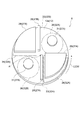
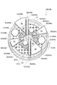
- FIG. 2 is a diagram illustrating a processing unit included in the three-dimensional printing apparatus of FIG. 1.
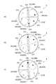
- FIG. 3 is a schematic diagram for explaining the operation of the three-dimensional printing apparatus.
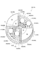
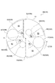
- FIG. 4 is a diagram illustrating a processing unit included in the three-dimensional printing apparatus according to the second embodiment.
- FIG. 5 is a diagram showing a processing area in the three-dimensional printing apparatus of FIG.
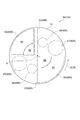
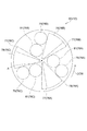
- FIG. 6 is a diagram illustrating a processing unit included in the three-dimensional printing apparatus according to the third embodiment.
- FIG. 7 is a diagram showing a processing area in the modeling apparatus of FIG.
- FIG. 8 is a diagram illustrating a processing area provided in a three-dimensional printing apparatus according to a modification.
- FIG. 9 is a diagram illustrating a processing area provided in a three-dimensional printing apparatus according to another modification.
- a three-dimensional modeling apparatus includes a table that supports a powder material and a model formed of the powder material, and is disposed to face the table, and processes the powder material to obtain a model. And a rotation drive unit for rotating one of the table and the processing unit relative to the other around the rotation axis.
- the processing unit has a plurality of processing units arranged around the rotation axis. The processing unit supplies the powder material to the table, preheats the supplied powder material, and irradiates the preheated powder material with an energy beam.
- the processing unit of this apparatus supplies the powder material to the table, preheats the powder material, and irradiates the powder material with an energy beam.
- a plurality of processing units performing these operations are arranged around the rotation axis. As a result, the supply operation by one processing unit and the supply operation by another processing unit can be performed in parallel. Similarly, the preheating operation by one processing unit and the preheating operation by another processing unit can be performed in parallel. Further, the modeling operation by one processing unit and the modeling operation by another processing unit can be performed in parallel. Therefore, the molding time can be further reduced.
- the processing unit of the three-dimensional printing apparatus may include a first beam providing unit and a second beam providing unit that provide an energy beam.
- the distance from the rotation axis to the second beam providing unit may be shorter than the distance from the rotation axis to the first beam providing unit.
- the modeled object can be formed by dividing the modeled object into the outer peripheral portion and the inner peripheral portion based on the rotation axis.
- the first beam providing unit of the three-dimensional printing apparatus may be arranged upstream of the second beam providing unit along the rotation direction provided by the rotation driving unit. According to this configuration, the portion on the outer peripheral side of the modeled object is formed first. That is, the temperature of the outer peripheral portion increases before the inner peripheral portion. As a result, the time during which the temperature of the outer peripheral portion is maintained at a high temperature is prolonged. Therefore, it is easy to suppress the temperature decrease of the modeled object.
- the processing unit of the three-dimensional printing apparatus may have a first preheating unit and a second preheating unit for preheating the powder material.
- the first preheating unit and the first beam providing unit may be arranged in this order along the rotation direction provided by the rotation driving unit.
- the second preheating unit and the second beam providing unit may be arranged in this order along the rotation direction provided by the rotation driving unit.
- the processing unit of the three-dimensional printing apparatus may include a first post-heating section and a second post-heating section that post-heat the formed object.
- the first beam providing unit and the first after-heating unit may be arranged in this order along the rotation direction provided by the rotation driving unit.
- the second beam providing unit and the second post-heating unit may be arranged in this order along the rotation direction provided by the rotation driving unit.
- the temperature of the powder material preheated by the first preheating section may be equal to the temperature of the molded article postheated by the first postheating section. According to this configuration, the temperature difference between the temperature of the powder material and the temperature of the molded object can be reduced.
- the temperature of the powder material preheated by the first preheating section may be different from the temperature of the molded article postheated by the first postheating section. According to this configuration, the temperature difference between the temperature of the powder material and the temperature of the molded object can be set to a desired value.
- the temperature of the powder material preheated by the second preheating section may be equal to the temperature of the molded article heated by the second postheating section. According to this configuration, the temperature difference between the temperature of the powder material and the temperature of the molded object can be reduced.
- the temperature of the powder material preheated by the second preheating section may be different from the temperature of the molded article heated by the second postheating section. According to this configuration, the temperature difference between the temperature of the powder material and the temperature of the molded object can be set to a desired value.
- the three-dimensional printing apparatus may further include a control unit that controls the processing unit and the rotation driving unit.
- the processing unit includes a material supply unit that supplies the powder material to a supply region set on the main surface of the table, and a material supply unit downstream of the supply region in the main surface of the table along the rotation direction provided by the rotation drive unit.
- a beam providing unit for irradiating an energy beam to the modeling region set to the above.
- the control unit controls the rotation drive unit to perform a rotation operation of rotating one of the table and the processing unit relative to the other, and controls the material supply unit to supply the powder material to the supply area.
- the shaping operation of irradiating the shaping region with the energy beam may be performed by performing the operation and controlling the beam providing unit.
- each operation for modeling the modeled object is performed in a different area from each other. Therefore, it becomes possible to execute each operation in parallel. As a result, the molding time can be reduced as compared with the case where each operation is sequentially performed to form a molded object.
- the control unit of the three-dimensional printing apparatus may perform the rotation operation, the supply operation, and the printing operation in parallel. According to this configuration, the molding time can be suitably reduced.
- the three-dimensional printing apparatus may further include a linear driving unit that relatively changes a distance between the table and the processing unit.
- the control unit may control the linear driving unit to perform a separating operation for increasing a distance along the rotation axis from the table to the processing unit.
- the powder materials are stacked while being processed. As a result, the height of the object increases. According to this configuration, it is possible to keep the distance between the powder material requiring processing and the modeling part constant. Therefore, the modeling part can be easily controlled.
- the control unit of the three-dimensional printing apparatus may perform the rotating operation, the supplying operation, the forming operation, and the separating operation in parallel. According to this configuration, it is possible to reduce the molding time required for molding the spirally stacked molded objects.
- the control unit of the three-dimensional modeling apparatus may perform the separating operation after performing the rotation operation, the supply operation, and the modeling operation in parallel. According to this configuration, it is possible to reduce the molding time required for molding the molded object constituted by the plurality of disk-shaped layers.
- the three-dimensional layered object manufacturing apparatus shown in FIG. 1 is a so-called 3D printer that manufactures the object 101S from the powder material 101.
- the three-dimensional layered object manufacturing apparatus is simply referred to as “three-dimensional object forming apparatus 1”.
- the powder material 101 is a metal powder.
- the powder material 101 is, for example, a titanium-based metal powder, an Inconel powder, an aluminum powder, or the like.
- the powder material 101 is not limited to a metal powder.
- the powder material 101 may be a powder containing carbon fiber and resin, such as CFRP (Carbon Fiber Reinforced Plastics).
- CFRP Carbon Fiber Reinforced Plastics
- the powder material 101 may be another powder having conductivity.
- the powder material used for the three-dimensional printing apparatus 1 of the present disclosure is not limited to a conductive material. For example, when a laser is used as an energy beam, the powder material may not have conductivity.
- the three-dimensional printing apparatus 1 applies energy to the powder material 101.
- the three-dimensional modeling apparatus 1 raises the temperature of the powder material 101.
- the powder material 101 is melted or sintered.
- the temperature of the powder material 101 decreases.
- the powder material 101 solidifies. That is, the three-dimensional modeling apparatus 1 manufactures the molded object 101S by repeating the application and stop of the energy a plurality of times.
- the modeled object 101S is, for example, a mechanical part. Note that the modeled object 101S may be another structure.
- the three-dimensional printing apparatus 1 includes a driving unit 3, a control unit 4, a processing unit 6, and a housing 8.
- the drive unit 3 realizes various operations required for modeling.
- the processing unit 6 processes the powder material 101.
- a formed object 101S is obtained.
- the treatment of the powder material 101 includes a supply process of the powder material 101, a pre-heat treatment of the powder material 101, and a shaping process of the powder material 101.
- the housing 8 is supported by a plurality of columns 7.
- the housing 8 forms a molding space S.
- the modeling space S stores the powder material 101.
- the modeling space S is a space for processing the powder material 101 by the processing unit 6.
- the modeling space S is an airtight space that can be decompressed.
- the table 13 is a processing table on which a modeling process is performed.
- the shape of the table 13 is, for example, a disk.
- a powder material 101 which is a raw material of the molded object 101S is arranged.
- the central axis of the table 13 overlaps with the central axis of the housing 8.
- the drive unit 3 is connected to the table 13.
- the table 13 is rotated and linearly moved along the rotation axis by the drive unit 3.
- the drive unit 3 rotates and moves the table 13 up and down.
- the drive unit 3 includes a rotation unit 15 (rotation drive unit) and a lifting unit 16 (linear drive unit).
- the rotation unit 15 rotates the table 13.
- the rotation unit 15 includes a drive source (for example, a motor).
- the upper end of the lifting unit 16 is connected to the table 13.
- the elevating unit 16 elevates and lowers the table 13 relative to the modeling tank 14. This elevation is along the rotation axis of the rotation unit 15.
- the drive part 3 should just be a mechanism which can rotate the table 13 and raise / lower.
- the drive unit 3 is not limited to the above mechanism.
- Fig. 2 shows the main parts used in the molding process in an enlarged manner.
- the processing unit 6 is arranged. That is, the processing unit 6 faces the modeling surface 13a (main surface) of the table 13.
- the processing unit 6 includes processing units 27A and 27B as a plurality of processing units.
- the processing units 27A and 27B are arranged at equal intervals (180 degrees) around the rotation axis A. In other words, the processing units 27A and 27B are, for example, equally arranged in the circumferential direction. According to this arrangement, the lamination thickness of the powder material 101 can be made uniform according to the rotation angle up to the next processing region.
- the arrangement of the processing units 27A and 27B described above is an example.
- the arrangement of the processing units 27A and 27B is not limited to the configuration. For example, the arrangement of the processing units 27A and 27B may be arranged at different angles in the circumferential direction.
- the processing unit 27A is arranged in the first quadrant and the fourth quadrant.
- the processing unit 27B is located in the second and third quadrants. That is, when the processing units 27A and 27B are equally arranged in the circumferential direction, they are arranged point-symmetrically with respect to the Y axis. When the processing units 27A and 27B are not arranged at the same position, they may not be arranged at point symmetry.
- the processing units 27A and 27B are arranged at different positions. The specific components of the processing units 27A and 27B are common. Note that the components of the processing units 27A and 27B may be different from each other. For example, the processing units 27A and 27B may be configured such that one of the constituent elements has the other part omitted. Hereinafter, the processing unit 27A will be described in detail. The processing unit 27B adds a description as needed.
- the processing unit 27A includes a feeder 28 (material supply unit), a heater 29, and a beam source 31 (first beam providing unit).
- the feeder 28 performs a supply process of the powder material 101.
- the heater 29 performs a pre-heat treatment on the powder material 101.
- the beam source 31 performs a shaping process on the powder material 101.
- the feeder 28 supplies the powder material 101 to the table 13.
- the feeder 28 has a raw material tank (not shown) and a leveling unit.
- the raw material tank stores the powder material 101.
- the raw material tank supplies the powder material 101 to the table 13.
- the leveling unit leveles the surface of the powder material 101 supplied to the table 13.
- the three-dimensional printing apparatus 1 may include a roller unit, a bar-shaped member, a brush unit, and the like, instead of the leveling unit.
- the heater 29 raises the temperature of the powder material 101 by radiant heat.
- an infrared heater may be used.
- a gas heater may be used.
- the beam source 31 generates an electron beam.
- the electron beam is applied to the powder material 101.
- the beam source 31 is, for example, an electron gun.
- the electron gun generates an electron beam according to a potential difference generated between a cathode and an anode.
- the feeder 28, the heater 29, and the beam source 31 are arranged in this order along the rotation direction of the table 13.
- the rotation direction of the table 13 is counterclockwise.
- “upstream” and “downstream” are based on the rotation direction of the table 13.
- Beam source 31 is located in the first quadrant.
- the feeder 28 and the heater 29 of the processing unit 27B are arranged in the second quadrant.
- the beam source 31 (second beam providing unit) is arranged in the third quadrant.
- the feeder 28, the heater 29, and the beam source 31 form processing regions 32A and 32B on the modeling surface 13a.
- the processing areas 32A and 32B revolve relatively to the table 13. That is, the three-dimensional printing apparatus 1 has a plurality of processing regions.
- “revolving relatively to the table 13” means that the positions of the processing regions 32A and 32B do not change with the rotation of the table 13. That is, when the table 13 and the processing areas 32A and 32B are defined by a certain coordinate system, the table 13 rotates with respect to the coordinate system. However, the processing regions 32A and 32B do not move with respect to the coordinate system.
- the processing region 32A includes a supply region 33, a preheating region 34, and a modeling region 36.
- the feeder 28 forms a supply area 33.
- the heater 29 forms a preheating area 34.
- the beam source 31 forms a modeling region 36.
- the positional relationship between the supply region 33, the preheating region 34, and the modeling region 36 corresponds to the positional relationship between the feeder 28, the heater 29, and the beam source 31.
- the supply area 33 and the preheating area 34 of the processing unit 27A are arranged in the fourth quadrant.
- the modeling region 36 is arranged in the first quadrant.
- the supply area 33 and the preheating area 34 of the processing unit 27B are arranged in the second quadrant.
- the modeling region 36 is arranged in the third quadrant.
- the supply region 33, the preheating region 34, and the modeling region 36 may be formed in this order along the rotation direction. Therefore, in the first quadrant and the fourth quadrant where the processing unit 27A is arranged, the area occupied by the supply area 33, the preheating area 34, and the modeling area 36 may be changed as appropriate.
- the preheating area 34 may be set from the fourth quadrant to the first quadrant, and the modeling area 36 may be set to the first quadrant.
- the preheating area 34 may be set in the fourth quadrant, and the modeling area 36 may be set from the fourth quadrant to the first quadrant.
- the table 13 rotates counterclockwise CCW.
- the point passes through the supply area 33, the preheating area 34, and the modeling area 36 in order with the rotation of the table 13.
- the supply area 33 is formed below the feeder 28.
- the shape of the supply region 33 is, for example, a rectangular shape whose longitudinal direction is the diameter direction (radial direction) of the table 13.
- the shape of the supply region 33 is not limited to a rectangular shape.
- Various shapes may be adopted as the shape of the supply region 33 according to the configuration of the feeder 28 and the like.
- the shape of the supply region 33 may be a square, a polygon, a circle, an ellipse, or the like.
- the supply area 33 extends from the center of the table 13 to the circumference of the table 13.
- the shape of the supply region 33 does not need to match the shape of the feeder 28 in plan view.
- the shape of the supply region 33 may be appropriately set according to the components included in the feeder 28.
- the powder material 101 is supplied to the table 13 from the feeder 28 to the supply area 33.
- the supplied powder material 101 is leveled to have a predetermined thickness.
- the supply area 33 may mean only an area to which the powder material 101 is supplied.
- the supply region 33 may mean only a region where the powder material 101 is leveled. Further, the supply region 33 may include a region where the powder material 101 is supplied and a region where the powder material 101 is leveled.
- the preheating area 34 is formed downstream of the supply area 33.
- the shape of the preheating region 34 is a fan shape. Specifically, the top is arranged near the rotation axis A of the table 13. The arc portion is arranged along the outer peripheral edge of the table 13.
- the central angle of the preheating region 34 is, for example, 90 degrees.
- the radius of the preheating region 34 substantially coincides with the length of the supply region 33 in the longitudinal direction.
- the radius of the preheating region 34 may be longer than the length of the supply region 33 in the longitudinal direction.
- the shape of the preheating region 34 is not limited to a sector shape.
- the shape of the preheating region 34 may adopt another shape.
- the shape of the preheating region 34 may be circular.
- the preheating region 34 is a region where the temperature of the powder material 101 is increased.
- the preheating here is a process of heating so that the temperature of the powder material 101 in the preheating region 34 is higher than the temperature of the powder material 101 in the supply region 33.
- Such a heating process may be, for example, a process of temporarily sintering the powder material 101.
- temporary sintering refers to a state where the powder materials 101 are diffused and joined at a minimum point by a diffusion phenomenon.
- the temperature of the powder material 101 is, for example, 1 / or more of the melting point of the powder material 101.
- the diffusion phenomenon of sintering becomes active.
- the powder material 101 is titanium
- the melting point of the titanium alloy is about 1500 ° C. or more and 1600 ° C. or less. Therefore, the temporary sintering temperature is 700 ° C. or more and 800 ° C. or less.
- the powder material 101 is aluminum
- the melting point of aluminum is about 660 ° C. Therefore, the preliminary sintering temperature is 300 ° C.
- the modeling region 36 is formed downstream of the preheating region 34.
- the shape of the modeling region 36 is circular.
- the shape of the modeling region 36 matches the irradiation range (irradiation range) of the beam source 31.
- the modeling region 36 is a region where the temperature of the powder material 101 is increased.
- the temperature of the powder material 101 in the modeling region 36 is higher than the temperature of the powder material 101 in the preheating region 34.
- the temperature of the powder material 101 in the modeling region 36 is a temperature at which the modeling object 101S can be formed.
- the temperature at which the modeled object 101S can be formed is a sintering temperature or a melting temperature.
- the beam source 31 irradiates an electron beam so as to scan a desired portion in the formation region 36.
- the shape of the modeling region does not have to match the shape of the irradiation range of the beam source.
- the modeling region may be a desired portion where the beam is scanned.
- the modeling region may be a region having a desired shape included in the irradiation range.
- the operation of the three-dimensional modeling apparatus 1 includes a first supply operation, a second supply operation, a first preheating operation, a second preheating operation, a first modeling operation, a second modeling operation, a rotation operation, and a descent. Operation.
- the processing unit 6 is fixed. That is, the processing areas 32A and 32B are fixed. The processing areas 32A and 32B do not rotate.
- the table 13 rotates in the counterclockwise direction CCW. Several areas are set in the table 13 for convenience of explanation. Some regions include a first region 37a, a second region 37b, a third region 37c, a fourth region 37d, a fifth region 37e, and a sixth region 37f. In FIG. 3, these areas are indicated by dots.
- the control unit 4 controls the rotation unit 15.
- the table 13 rotates at a constant rotation speed in the counterclockwise direction CCW.
- This rotation speed may be determined based on the temperature rise in the preheating region 34 and the temperature rise in the modeling region 36. For example, the amount of energy required to raise the temperature of the powder material 101 before preheating to a predetermined temperature after preheating is obtained. Next, the time required to apply the energy amount to the powder material 101 is determined. Then, according to the required time and the length of the trajectory passing when passing through the preheating region 34, a rotation speed can be obtained.
- the control unit 4 controls the lifting unit 16. As a result, the table 13 continuously moves downward with the passage of time. This operation is called a separating operation.
- the moving speed of the table 13 may be determined by the thickness of the layer formed every time the table 13 makes one rotation.
- the first region 37a receives the first supply operation in the supply region 33.
- Second region 37b receives a first preheating operation in preheating region 34.
- the third region 37c receives the first modeling operation in the modeling region 36.
- the fourth region 37d receives the second supply operation in the supply region 33.
- Fifth region 37e receives a second preheating operation in preheating region.
- the sixth region 37f receives the second modeling operation in the modeling region 36.
- the processing unit 27A performs the first preheating operation on the second region 37b in parallel with the first supply operation on the first region 37a.
- the processing unit 27A performs the first modeling operation on the third region 37c in parallel with the first supply operation on the first region 37a.
- the processing unit 27B performs the second preheating operation on the fifth region 37e in parallel with the second supply operation on the fourth region 37d.
- the processing unit 27B performs the second modeling operation on the sixth region 37f in parallel with the second supply operation on the fourth region 37d.
- the table 13 rotates by a predetermined angle.
- the state becomes the second state shown in FIG.
- the first region 37 a undergoes a first preheating operation in the preheating region 34.
- the second region 37b receives the first modeling operation in the modeling region 36.
- the third region 37c receives the second supply operation in the supply region 33.
- the fourth region 37d receives a second preheating operation in the preheating region 34.
- the fifth region 37e receives the second modeling operation in the modeling region 36.
- the sixth region 37f receives the first supply operation in the supply region 33.
- the processing unit 27A performs the first modeling operation on the second region 37b in parallel with the first preheating operation on the first region 37a.
- the processing unit 27A performs the first supply operation on the sixth region 37f in parallel with the first preheating operation on the first region 37a.
- the processing unit 27B performs the second modeling operation on the fifth region 37e in parallel with the second preheating operation on the fourth region 37d.
- the processing unit 27B performs the second supply operation on the first region 37a in parallel with the second preheating operation on the fourth region 37d.
- the table 13 rotates by a predetermined angle.
- a third state shown in FIG. When in the third state, the first region 37 a receives the first modeling operation in the modeling region 36.
- the second region 37b receives the second supply operation in the supply region 33.
- Third region 37c receives a second preheating operation in preheating region 34.
- the fourth region 37d receives the second modeling operation in the modeling region 36.
- the fifth region 37e receives the first supply operation in the supply region 33.
- the sixth region 37f receives the first preheating operation in the preheating region 34.
- the processing unit 27A performs the first supply operation on the fifth region 37e in parallel with the first modeling operation on the first region 37a.
- the processing unit 27A performs a first preheating operation on the sixth region 37f in parallel with the first modeling operation on the first region 37a.
- the processing unit 27B performs the second supply operation on the second region 37b in parallel with the second modeling operation on the fourth region 37d.
- the processing unit 27B performs the second preheating operation on the third region 37c in parallel with the second modeling operation on the fourth region 37d.
- the processing units 27A and 27B of the three-dimensional printing apparatus 1 spread the powder material 101 on the table 13, preheat the powder material 101, and irradiate the powder material 101 with an electron beam.
- a plurality of processing units 27A and 27B that perform these operations are arranged around the rotation axis A.
- the supply operation by the processing unit 27A and the supply operation by the processing unit 27B can be performed in parallel.
- the preheating operation by the processing unit 27A and the preheating operation by the processing unit 27B can be performed in parallel.
- the modeling operation by the processing unit 27A and the modeling operation by the processing unit 27B can be performed in parallel. Therefore, the molding time can be further reduced.
- the three-dimensional modeling apparatus 1 performs a supply operation, a preheating operation, and a molding operation for molding the molded object 101S in regions different from each other. As a result, each operation can be performed in parallel. Therefore, the molding time can be reduced as compared with the case where the molded object 101S is molded by sequentially performing each operation.
- the three-dimensional printing apparatus 1 further includes a control unit 4 that controls the processing unit 6 and the rotation unit 15.
- the control unit 4 controls the rotation unit 15 to perform a rotation operation for rotating the table 13 with respect to the processing unit 6.
- the control unit 4 performs a supply operation of controlling the two feeders 28 to supply the powder material 101 to two supply areas 33.
- the control unit 4 controls the two beam sources 31 to perform a shaping operation of irradiating two shaping areas 36 with an electron beam. According to this configuration, the molding time can be suitably reduced.
- the three-dimensional printing apparatus 1 further includes a lifting unit 16 that relatively changes the distance between the table 13 and the processing unit 6.
- the control unit 4 controls the elevating unit 16 to perform a descending operation for increasing the distance along the rotation axis A from the table 13 to the processing unit 6.
- the powder material 101 is laminated while being processed.
- the height of the modeled object 101S increases. According to this configuration, the distance from the powder material 101 requiring processing to the processing unit 6 can be kept constant. Therefore, control of the processing unit 6 can be facilitated.
- the printing surface 13a of the three-dimensional printing apparatus 1 is revolved relatively around the rotation axis A with respect to the table 13 and is set downstream of the feeder 28 and upstream of the beam source 31.
- a preheating region 34 is formed.
- the processing section 6 further includes a heater 29 for heating the powder material 101 existing in the preheating region 34.
- the control unit 4 of the three-dimensional printing apparatus 1 performs a supply operation, a preheating operation, a modeling operation, a rotation operation, and a lowering operation in parallel. According to this control mode, it is possible to reduce the molding time required for molding the spirally laminated molded article 101S. In other words, the three-dimensional printing apparatus 1 can reduce the tact time.
- the reduction of the molding time will be described while exemplifying the time required for each operation.
- the supply operation is t1.
- the preheating operation is t2.
- the modeling operation is t3.
- the descending operation is at t5.
- the magnitude relation at each time is t1 ⁇ t5 ⁇ t2 ⁇ t3.
- the time required to form one layer of the molded object 101S is the sum of the respective times. That is, the molding time is t1 + t2 + t3 + t5.
- the respective operations are performed in parallel as in the three-dimensional printing apparatus 1, the printing time is t2 or t3.
- the molding time is determined by the operation that requires the longest time. Therefore, the molding time can be reduced as compared with the case where each operation is performed sequentially. In particular, when two or more operations requiring time are included, the effect of shortening the time is high.
- the operation that requires time is exemplified by, for example, a preheating operation and a modeling operation.
- the parallel processing energy loss can be reduced.
- the electron beam irradiation is not performed during the execution of the supply operation and during the execution of the descent operation.
- the heating process is not performed during the execution of the supply operation and the execution of the descent operation. That is, on the table 13, the operation with heating and the operation without heating are repeated.
- the operation with heating and the operation without heating are repeated.
- the temperature environment of the modeling surface 13a changes. Specifically, the temperature of the modeling surface 13a decreases. Then, when the operation is switched to the operation involving heating again, energy for increasing the temperature of the reduced amount is required.
- the preheating operation is always performed in the preheating region 34. That is, the heating process is performed by the heater. Therefore, in the preheating region 34, heating and non-heating are not repeated. As a result, a decrease in temperature that occurs during non-heating is also suppressed. Then, since energy for raising the temperature for the lowered temperature is not required, energy loss can be reduced. The same applies to the modeling region 36.
- the modeling surface 13a moves with respect to the fixed heater 29 and the beam source 31. Therefore, there is no need to prepare a large-scale heater 29 and a beam source 31 that cover the entire surface of the modeling surface 13a. Then, the number of expensive electron guns required for the heater 29 and the beam source 31 can be reduced. As a result, cost can be reduced.
- a three-dimensional printing apparatus 1A according to a second embodiment will be described with reference to FIGS.
- the three-dimensional printing apparatus 1A according to the second embodiment includes a processing unit 6A.
- the processing unit 6A has processing units 38A and 38B.
- the positions of the processing units 38A and 38B with respect to the table 13 are the same as those of the processing units 27A and 27B of the first embodiment.
- the configuration of the processing unit 38A will be described in detail, and the description of the processing unit 38B that is common to the processing unit 38A will be omitted.
- the “region on the outer peripheral side” refers to an outer region when the powder material 101 spread in a circular or annular shape in plan view and divided in the radial direction.
- the “region on the inner peripheral side” refers to an inner region when the powder material 101 spread in a circular shape or an annular shape in plan view and divided in the radial direction.
- the area on the outer peripheral side is called an outer peripheral area 101a.
- the area on the inner circumference side is called an inner circumference area 101b.
- it is an annular shape of the outer peripheral region 101a and surrounds the inner peripheral region 101b.
- the inner peripheral edge of the outer peripheral region 101a is in contact with the outer peripheral edge of the inner peripheral region 101b.
- the outer peripheral region 101a and the inner peripheral region 101b may partially overlap with each other, in addition to those in contact with each other.
- the outer peripheral region 101a and the inner peripheral region 101b may not overlap each other.
- the relationship between the outer peripheral region 101a and the inner peripheral region 101b is exemplified by three modes, but these modes may be different for each powder layer.
- the outer peripheral region 101a and the inner peripheral region 101b may be in contact with each other, and in another powder layer, the outer peripheral region 101a and the inner peripheral region 101b may partially overlap.
- the relationship between the outer peripheral area 101a and the inner peripheral area 101b may be appropriately set according to the shape of the object.
- the outer peripheral edge of the outer peripheral region 101a may be common to the outer peripheral edge of the powder material 101.
- the outer peripheral edge of the outer peripheral region 101a may be formed inside the outer peripheral edge of the powder material 101.
- the shape of the inner peripheral region 101b is a ring or a circle, and is surrounded by the outer peripheral region 101a.
- the processing units 38A and 38B include the feeder 28, the heater 39, the outer beam source 41, and the inner beam source 42.
- the processing unit 38A forms a processing area 40A shown in FIG.
- the processing unit 38B forms a processing area 40B shown in FIG.
- the processing regions 40A and 40B include a supply region 33, an outer peripheral preheating region 44, an inner peripheral preheating region 46, an outer peripheral molding region 47, and an inner peripheral molding region 48.
- the heater 39 forms an outer peripheral preheating region 44 and an inner peripheral preheating region 46.
- a region including the outer peripheral preheating region 44 and the inner peripheral preheating region 46 is referred to as a total preheating region 50.
- the shape of the overall preheating region 50 of the heater 39 is different from the shape of the preheating region 34 of the heater 29 of the first embodiment.
- the overall preheating region 50 formed in the fourth quadrant has a fan-like shape.
- the central angle of the overall preheating region 50 may be, for example, 90 degrees, may be larger than 90 degrees, or may be smaller than 90 degrees.
- the central angle of the overall preheating region 50 may be 90 degrees.
- heater 39 includes a first preheating unit 51 and a second preheating unit 52.
- the first preheating section 51 forms the outer peripheral preheating region 44.
- the second preheating section 52 forms an inner peripheral preheating area 46.
- the outer beam source 41 forms the outer modeling area 47.
- the outer beam source 41 provides an electron beam to the powder material 101 located on the outer peripheral side of the table 13.
- the inner beam source 42 forms an inner peripheral modeling region 48.
- the inner beam source 42 provides an electron beam to the powder material 101 located on the inner peripheral side of the table 13.
- the outer beam source 41 is arranged on the outer peripheral side of the inner beam source 42.
- the distance from the rotation axis A to the outer beam source 41 is longer than the distance from the rotation axis A to the inner beam source 42.
- the distance from the rotation axis A to the inner beam source 42 is shorter than the distance from the rotation axis A to the outer beam source 41.
- the outer beam source 41 is arranged upstream of the inner beam source 42. In other words, in the circumferential direction, the distance from the outer peripheral preheating region 44 to the outer beam source 41 is shorter than the distance from the inner peripheral preheating region 46 to the inner beam source 42.
- the outer beam source 41 may be located in the fourth quadrant.
- the inner beam source 42 may be located in the first quadrant.
- the range in which the outer beam source 41 can irradiate the electron beam is the outer peripheral forming area 47.
- the outer beam source 41 irradiates a desired portion in the outer modeling area 47 so as to scan the electron beam.
- the irradiable range of the electron beam in the inner beam source 42 is the inner peripheral modeling region 48.
- the inner beam source 42 irradiates a desired portion in the inner peripheral shaping region 48 so as to scan the electron beam.
- the area of the outer peripheral shaping region 47 may be larger, the same, or smaller than the inner peripheral shaping region 48. Further, the shape of the outer peripheral shaping region 47 may be a circular shape or another shape. Further, the relationship between the outer peripheral shaping region 47 and the inner peripheral shaping region 48 can take various forms. That is, the relationship between the outer modeling region 47 and the inner modeling region 48 may be such that they are in contact with each other, may be partially overlapping, or may be non-overlapping.
- the outer peripheral molding region 47 does not have to overlap the inner peripheral molding region 48.
- the outer beam source 41 is disposed upstream of the inner beam source 42. Therefore, the outer peripheral shaping region 47 does not overlap the inner peripheral shaping region 48. As a result, mutual interference between the electron beam of the outer beam source 41 and the electron beam of the inner beam source 42 can be prevented. Therefore, control of the outer beam source 41 and the inner beam source 42 can be simplified.
- the outer peripheral preheating region 44 and the outer peripheral modeling region 47 are set on a common reference circle.
- the powder material 101 that has passed through the outer peripheral preheating region 44 is provided to the outer peripheral modeling region 47.
- the inner peripheral preheating region 46 and the inner peripheral forming region 48 are also set on a common reference circle.
- the powder material 101 that has passed through the inner peripheral preheating region 46 is provided to the inner peripheral modeling region 48.
- the processing units 38A and 38B of the above-described three-dimensional printing apparatus 1A include an outer beam source 41 and an inner beam source 42 that provide an electron beam.
- the distance from the rotation axis A to the inner beam source 42 is shorter than the distance from the rotation axis A to the outer beam source 41.
- the modeled object 101S can be formed by dividing the modeled object 101S into an outer peripheral portion and an inner peripheral portion based on the rotation axis A.
- the outer beam source 41 of the three-dimensional printing apparatus 1A is arranged upstream of the inner beam source 42 along the rotation direction provided by the driving unit 3. According to this configuration, the outer peripheral portion of the modeled object 101S is formed first. That is, the temperature of the outer peripheral portion increases before the inner peripheral portion. As a result, the time during which the temperature of the outer peripheral portion is kept high is long. As a result, it is easy to suppress a decrease in the temperature of the modeled object 101S.
- the processing units 38A and 38B of the three-dimensional modeling apparatus 1A have a first preheating unit 51 and a second preheating unit 52 for preheating the powder material 101.
- the processing units 38A and 38B are arranged in the order of the first preheating unit 51 and the outer beam source 41 along the rotation direction provided by the driving unit 3.
- the second preheating unit 52 and the inner beam source 42 are arranged in this order along the rotation direction provided by the driving unit 3. According to this configuration, the powder material 101 provided to the outer beam source 41 can be reliably preheated by the first preheating unit 51. Similarly, the powder material 101 provided to the inner beam source 42 can be reliably preheated by the second preheating unit 52.
- a three-dimensional printing apparatus 1B according to a third embodiment will be described with reference to FIGS.
- the three-dimensional printing apparatus 1B of the third embodiment has a processing unit 6B.
- the processing unit 6B includes processing units 49A and 49B.
- the configuration of the processing unit 49A will be described in detail. Description of the processing unit 49B that is common to the processing unit 49A will be omitted.
- the processing unit 49A forms a processing area 53A.
- the processing unit 49B forms a processing area 53B.
- the processing unit 49A includes the feeder 28, the upstream heater 54, the downstream heater 55, the outer beam source 41, and the inner beam source 42. That is, the processing unit 49A of the third embodiment includes two heaters.
- the upstream heater 54 has the same configuration as the heater 39 of the second embodiment.
- the downstream heater 55 is disposed between the outer beam source 41 and the inner beam source 42 in a circumferential direction around the rotation axis A.
- the upstream heater 54 has a first preheating section 56 and a second preheating section 57.
- the first preheating portion 56 forms an outer peripheral preheating region 58.
- the second preheating section 57 forms an upstream inner peripheral preheating area 59.
- the outer peripheral preheating region 58 and the upstream inner peripheral preheating region 59 constitute an upstream heating region 60.
- the outer peripheral preheating region 58 has the same configuration as the outer peripheral preheating region 44 of the second embodiment.
- the upstream inner peripheral preheating region 59 has the same configuration as the inner peripheral preheating region 46 of the second embodiment.
- the downstream heater 55 has a first after-heating section 61 and a third pre-heating section 62.
- post-heating is used as a term that is paired with “preheating”. Specifically, “preheating” means a process performed before the shaping process by the beam source 31. “Post-heat” means a process performed after the shaping process by the beam source 31. Therefore, the processing flow of the three-dimensional modeling apparatus 1A is performed in the order of the supply processing, the pre-heat treatment, the molding processing, and the post-heat treatment.
- the first post-heating section 61 forms the outer peripheral post-heating area 63.
- the third preheating section 62 forms a downstream inner peripheral preheating area 64.
- the post-outer-peripheral heat region 63 and the downstream inner-peripheral preheat region 64 constitute a downstream heating region 66.
- the downstream heater 55 is arranged downstream of the outer beam source 41. On the other hand, the downstream heater 55 is disposed upstream of the inner beam source 42. Then, the processing target of the downstream heater 55 includes a portion processed by the outer beam source 41 and a portion not processed by the inner beam source 42.
- the outer peripheral heat region 63 heats a portion formed by the outer beam source 41.
- the downstream inner circumference preheating region 64 heats a portion that has not yet been shaped by the inner beam source 42.
- the powder material 101 includes, in this order, a portion passing through the outer peripheral preheating region 58, the outer peripheral forming region 47, and the outer peripheral post-heating region 63, and an upstream inner peripheral preheating region 59, a downstream inner peripheral preheating region 64, and an inner peripheral forming region 48 in this order. And a passing part.
- the processing units 49A and 49B of the three-dimensional printing apparatus 1B have the downstream heater 55 for heating the printing object 101S.
- the outer beam source 41 and the downstream heater 55 are arranged in this order along the rotation direction provided by the driving unit 3. According to this configuration, the temperature of the modeled object 101S is maintained by the downstream heater 55. Therefore, it is possible to suppress a decrease in the temperature of the new powder material 101 further supplied from the processing unit 49B onto the modeled object 101S processed by the processing unit 49A.
- the three-dimensional printing apparatus of the present disclosure is not limited to the above embodiment.
- each component can appropriately change its shape, arrangement, and the like without departing from the scope of the claims.
- the operation of the three-dimensional printing apparatus has been described by exemplifying a mode in which the plurality of preheating units and the plurality of beam providing units are simultaneously operated.
- the plurality of preheating units and the plurality of beam providing units may be operated simultaneously as described above, or only necessary components may be operated according to the shape of the modeled object. Unnecessary components may be deactivated. That is, one of the plurality of preheating units and the plurality of beam providing units may be selected depending on the shape of the modeled object, or the state may be switched to a state of using all of them.
- both the preheating and melting in the outer peripheral region 101a and the preheating and melting in the inner peripheral region 101b may not necessarily be performed on the same powder layer depending on the shape of the modeled object.
- a region where the powder should be melted exists only in one of the inner peripheral region and the outer peripheral region.
- the region where the powder should be melted is the cross section of the modeled object.
- a cylindrical molded article having a portion having a different outer diameter is molded. Examples of such a shape include, for example, a truncated conical surface.
- a portion where the outer diameter of the modeled object is large there may be a case where there is no portion to be formed in the inner peripheral region 101b and a portion to be formed in the outer peripheral region 101a.
- a portion to be formed exists in the inner peripheral region 101b and a portion to be formed does not exist in the outer peripheral region 101a.
- modeling may not be performed in the inner peripheral region 101b but may be performed in the outer peripheral region 101a in a portion where the outer diameter of the modeled object is large.
- the modeling in the outer peripheral region 101a may be performed while the operations of the second preheating unit 52 and the inner beam source 42 are stopped. Then, in a portion where the outer diameter of the modeled object is small, the modeling in the inner peripheral region 101b may be performed and the modeling in the outer peripheral region 101a may not be performed. In other words, in the portion where the outer diameter of the modeled object is small, the modeling in the inner peripheral region 101b may be performed, and the operations of the first preheating unit 51 and the outer beam source 41 may be stopped.
- the three-dimensional printing apparatus 1C of the first modification may have a processing unit 6C.
- the processing unit 6C forms the processing regions 67A and 67B.
- the processing regions 67A and 67B include a supply region 33, an outer peripheral preheating region 68, an outer peripheral molding region 69, and an outer peripheral post-heating region 71, and an inner peripheral preheating region 72, an inner peripheral molding region 73, and an inner peripheral region.
- a post-heating region 74 may be included.
- the configuration of the heater is not particularly limited.
- the outer peripheral preheating region 68, the outer peripheral postheating region 71, the inner peripheral preheating region 72, and the inner peripheral postheating region 74 may be formed by one heater that can heat the entire surface of the table 13. That is, the heating area provided by one heater includes two outer preheating areas 68, two outer postheating areas 71, two inner preheating areas 72, and two inner preheating areas.
- the thermal region 74 may be included.
- each region may be formed by a plurality of heaters. That is, the outer peripheral preheating region 68 of the processing region 67A may be formed by the first heater 82.
- the second heater 83 may form the outer peripheral post-heating region 71 of the processing region 67A.
- the inner peripheral preheating region 72 of the processing region 67A may be formed by the third heater 84.
- the fourth heater 86 may form the inner peripheral post-heating region 74 of the processing region 67A.
- the outer peripheral preheating region 68 of the processing region 67B may be formed by the fifth heater 87.
- the outer peripheral post-heating region 71 of the processing region 67B may be formed by the sixth heater 88 (first post-heating unit).
- the inner peripheral preheating region 72 of the processing region 67B may be formed by the seventh heater 89.
- the eighth heater 91 second post-heating unit
- the temperature here may be a target temperature of the first heater 82, the outer beam source 41, and the second heater 83. Further, the temperature may be a temperature obtained by actually measuring the powder material 10. Further, the temperature may be a temperature obtained by actually measuring the molded object 101S. According to this configuration, the temperature difference between the temperature of the powder material 101 and the temperature of the molded object 101S can be reduced.
- the preheating temperature (T1) and the postheating temperature (T3) may be different (T2> T1 ⁇ T3).
- the preheating temperature (T1) may be higher than the afterheating temperature (T3) (T2> T1> T3).
- the preheating temperature (T1) may be lower than the afterheating temperature (T3) (T2> T3> T1). According to this configuration, the temperature difference between the temperature of the powder material 101 and the temperature of the molded object 101S can be set to a desired value.
- the above temperature relationship is the same on the inner circumference side. That is, the temperature (T 4) of the powder material 101 preheated by the third heater 84, the temperature (T 5) of the powder material 101 heated by the inner beam source 42, and the powder post-heated by the fourth heater 86.
- the three-dimensional printing apparatus 1D of Modification 2 may form three sets of processing regions.
- the processing unit 6D forms processing regions 76A, 76B, and 76C. These processing regions are arranged at equal intervals (120 degrees).
- the processing region 76A has a supply region 77, a preheating region 78, an outer molding region 79, and an inner molding region 81 similar to the processing region 40A of the second embodiment.
- the configuration of the processing area 76A may be the same as the configuration of the processing area 32A of the first embodiment.
- the configuration of the processing area 76A may be the same as the configuration of the processing area 53A of the third embodiment. With such a configuration, the supply operation, the preheating operation, and the molding operation can be performed in parallel. Therefore, the molding time can be reduced.
- the pre-heating unit, the beam providing unit, and the post-heating unit may operate only necessary components and stop operation of unnecessary components according to the shape of the modeled object.
- the configuration for performing post-heating is, for example, a configuration that includes the three-dimensional modeling device 1B illustrated in FIGS. 6 and 7 and the three-dimensional modeling device 1C illustrated in FIG. That is, one of the plurality of preheating units, the plurality of beam providing units, and the afterheating unit may be selected according to the shape of the modeled object. You may switch to a state where all are used.
- the preheating, melting, and post-heating in the outer peripheral region 101a and the preheating, melting, and post-heating in the inner peripheral region 101b may not necessarily be performed on the same powder layer depending on the shape of the modeled object.
- the modeling may not be performed at the inner peripheral area 101b but may be performed at the outer peripheral area 101a.
- the operations of the second preheating unit 57, the inner beam source 42, and the third preheating unit 62 may be stopped, and the modeling in the outer peripheral region 101a may be performed.
- the modeling in the inner peripheral region 101b may be performed, and the modeling in the outer peripheral region 101a may not be performed.
- the modeling in the inner peripheral region 101b may be performed, and the operations of the first preheating unit 56, the outer beam source 41, and the first post-heating unit 61 may be stopped.
- the modeling may not be performed at the inner peripheral area 101b but may be performed at the outer peripheral area 101a.
- the operation of the third heater 84 for preheating, the seventh heater 89, the inner beam source 42, the fourth heater 86 for post-heating, and the eighth heater 91 in the portion where the outer diameter of the modeled object is large. May be stopped, and modeling in the outer peripheral area 101a may be performed.
- the modeling in the inner peripheral region 101b may be performed and the modeling in the outer peripheral region 101a may not be performed.
- the operation of the first heater 82, the fifth heater 87, the outer beam source 41, the second heater 83, and the sixth heater 88 for preheating is performed in a portion where the outer diameter of the object is small. May be stopped.
- the beam source 31 may be provided so as to be movable in the diameter direction of the table 13.
- the beam source 31 may be configured to be mutually movable between a position where the outer peripheral region is heated and a position where the inner peripheral region is heated.
- the position of the beam source 31 may be selected, for example, according to the shape of the object. In other words, the beam source 31 may be moved in accordance with the shape of the object, and the position of the beam source 31 in the radial direction may be adjusted for each powder layer.
- the lowering operation may not be performed in parallel with the preheating operation and the modeling operation.
- the control unit 4 performs a supply operation, a preheating operation, a molding operation, and a rotation operation in parallel.
- the lowering operation is not performed in parallel with the supply operation, the preheating operation, the molding operation, and the rotation operation. According to this control, it is possible to obtain a model having a structure in which thin disks are stacked.
- Each component of the three-dimensional printing apparatus may be replaced with another component capable of performing a required function.
- an electron beam or a laser may be used for the preheating operation.
- an electron gun or a laser generator may be used instead of the heaters 29 and 39.
- an electron beam or a laser may be used.
- an electron gun or a laser generator is used instead of the downstream heater 55, the second heater 83 for post-heating, the fourth heater 86, the sixth heater 88, the eighth heater 91, and the like. May be used.
- the powder material was melted by electron beam irradiation.
- the beam applied to the powder material is not limited to an electron beam. That is, the beam applied to the powder material may be another energy beam.
- the beam used in the three-dimensional additive manufacturing apparatus may be any energy beam that can supply energy to the powder material 101.
- a modeling device to which a laser melting method is applied may be used.
- the beam used in the three-dimensional additive manufacturing apparatus may be a laser beam.
- the beam used in the three-dimensional additive manufacturing apparatus may be a charged particle beam, which is a concept including an electron beam and an ion beam.
- the configuration in which the rotation direction of the table 13 is the counterclockwise direction has been exemplified.
- the rotation direction of the table 13 is not limited to the counterclockwise direction.
- the rotation direction of the table 13 may be clockwise.
Landscapes
- Engineering & Computer Science (AREA)
- Chemical & Material Sciences (AREA)
- Manufacturing & Machinery (AREA)
- Materials Engineering (AREA)
- Mechanical Engineering (AREA)
- Toxicology (AREA)
- General Health & Medical Sciences (AREA)
- Health & Medical Sciences (AREA)
- Analytical Chemistry (AREA)
- Automation & Control Theory (AREA)
- Physics & Mathematics (AREA)
- Optics & Photonics (AREA)
- Plasma & Fusion (AREA)
- Powder Metallurgy (AREA)
Abstract
L'invention concerne un dispositif de modélisation en trois dimensions qui est pourvu de : une table qui supporte un matériau en poudre et un modèle créé à partir du matériau en poudre ; une section de traitement qui est disposée de façon à faire face à la table et qui obtient le modèle en traitant le matériau en poudre ; et une unité de rotation pour amener la table à tourner par rapport à la section de traitement autour d'un axe de rotation. La section de traitement comporte de multiples unités de traitement disposées autour de l'axe de rotation. Les unités de traitement fournissent le matériau en poudre à la table, préchauffent le matériau en poudre fourni et émettent un faisceau d'énergie vers le matériau en poudre préchauffé.
Priority Applications (3)
| Application Number | Priority Date | Filing Date | Title |
|---|---|---|---|
| JP2020527605A JP7196918B2 (ja) | 2018-06-26 | 2019-06-26 | 三次元造形装置 |
| EP19827281.7A EP3815818A4 (fr) | 2018-06-26 | 2019-06-26 | Dispositif de modélisation en trois dimensions |
| US17/253,722 US11524338B2 (en) | 2018-06-26 | 2019-06-26 | Three-dimensional modeling device |
Applications Claiming Priority (2)
| Application Number | Priority Date | Filing Date | Title |
|---|---|---|---|
| JP2018120674 | 2018-06-26 | ||
| JP2018-120674 | 2018-06-26 |
Publications (1)
| Publication Number | Publication Date |
|---|---|
| WO2020004507A1 true WO2020004507A1 (fr) | 2020-01-02 |
Family
ID=68986590
Family Applications (1)
| Application Number | Title | Priority Date | Filing Date |
|---|---|---|---|
| PCT/JP2019/025482 Ceased WO2020004507A1 (fr) | 2018-06-26 | 2019-06-26 | Dispositif de modélisation en trois dimensions |
Country Status (4)
| Country | Link |
|---|---|
| US (1) | US11524338B2 (fr) |
| EP (1) | EP3815818A4 (fr) |
| JP (1) | JP7196918B2 (fr) |
| WO (1) | WO2020004507A1 (fr) |
Cited By (2)
| Publication number | Priority date | Publication date | Assignee | Title |
|---|---|---|---|---|
| JP2021195611A (ja) * | 2020-06-18 | 2021-12-27 | トヨタ自動車株式会社 | 積層造形方法、及び積層造形装置 |
| WO2022215410A1 (fr) * | 2021-04-05 | 2022-10-13 | 株式会社Ihi | Dispositif rotatif de fabrication additive et dispositif de commande |
Families Citing this family (3)
| Publication number | Priority date | Publication date | Assignee | Title |
|---|---|---|---|---|
| US12343799B2 (en) * | 2019-04-02 | 2025-07-01 | Ihi Corporation | Three-dimensional manufacturing apparatus |
| WO2021001878A1 (fr) * | 2019-07-01 | 2021-01-07 | 株式会社ニコン | Dispositif de moulage |
| GB202210688D0 (en) * | 2022-07-21 | 2022-09-07 | Rolls Royce Plc | Apparatus and method |
Citations (9)
| Publication number | Priority date | Publication date | Assignee | Title |
|---|---|---|---|---|
| JP2005534543A (ja) | 2002-08-02 | 2005-11-17 | イーオーエス ゲゼルシャフト ミット ベシュレンクテル ハフツング イレクトロ オプティカル システムズ | 生成的製造法による三次元物体を製造するためのデバイスおよび方法 |
| JP2007503342A (ja) | 2003-05-23 | 2007-02-22 | ズィー コーポレイション | 三次元プリント装置及び方法 |
| JP2009544501A (ja) | 2006-07-27 | 2009-12-17 | アルカム アーベー | 3次元物体を生成する方法および装置 |
| JP2015533680A (ja) * | 2012-08-29 | 2015-11-26 | カーピーズ エスアーエスCarpyz Sas | 層ごとの追加によって円形製品を生産するための機械 |
| JP2015533650A (ja) | 2012-07-27 | 2015-11-26 | エアロジェット ロケットダイン オブ ディーイー,インコーポレイテッド | 選択的レーザ溶融の固体軸対称粉末床 |
| JP2016526098A (ja) | 2013-05-23 | 2016-09-01 | ア−カム アーベー | 付加製造のための方法および装置 |
| JP2016529389A (ja) | 2013-06-28 | 2016-09-23 | ア−カム アーベー | 付加製造のための方法および装置 |
| JP2016179500A (ja) | 2015-03-23 | 2016-10-13 | リンカーン グローバル, インコーポレイテッドLincoln Global, Inc. | 高エネルギー源とホットワイヤを用いた付加製造のための方法とシステム |
| JP2018507957A (ja) | 2014-12-15 | 2018-03-22 | ア−カム アーベー | 付加製造のための改良された方法 |
Family Cites Families (17)
| Publication number | Priority date | Publication date | Assignee | Title |
|---|---|---|---|---|
| TWI472427B (zh) * | 2012-01-20 | 2015-02-11 | 財團法人工業技術研究院 | 粉體鋪層裝置與方法及其積層製造方法 |
| US9937580B2 (en) | 2014-01-24 | 2018-04-10 | Lincoln Global, Inc. | Method and system for additive manufacturing using high energy source and hot-wire |
| US10046419B2 (en) | 2014-01-24 | 2018-08-14 | Lincoln Global, Inc. | Method and system for additive manufacturing using high energy source and hot-wire |
| US10464168B2 (en) | 2014-01-24 | 2019-11-05 | Lincoln Global, Inc. | Method and system for additive manufacturing using high energy source and hot-wire |
| US20150209910A1 (en) | 2014-01-24 | 2015-07-30 | Lincoln Global, Inc. | Method And System For Additive Manufacturing Of Cooling Passages Using High Energy Source |
| US9808886B2 (en) | 2014-01-24 | 2017-11-07 | Lincoln Global, Inc. | Method and system for additive manufacturing using high energy source and hot-wire |
| US9833862B2 (en) | 2014-01-24 | 2017-12-05 | Lincoln Global, Inc. | Method and system for additive manufacturing using high energy source and hot-wire |
| US9839978B2 (en) | 2014-01-24 | 2017-12-12 | Lincoln Global, Inc. | Method and system for additive manufacturing using high energy source and hot-wire |
| DE102014221885A1 (de) * | 2014-10-28 | 2016-04-28 | Koenig & Bauer Ag | Vorrichtung zum schichtweisen Aufbau von mindestens einem dreidimensionalen Werkstück |
| WO2016096407A1 (fr) | 2014-12-15 | 2016-06-23 | Arcam Ab | Procédé et appareil de fabrication additive faisant appel à un système de coordonnées angulaire bidimensionnel |
| EP3156153B1 (fr) * | 2015-10-16 | 2019-05-22 | SLM Solutions Group AG | Appareil de production d'une pièce de travail tridimensionnelle, qui comprend un système de chauffage |
| ITUA20163108A1 (it) | 2016-05-03 | 2017-11-03 | 3D New Tech S R L | Apparecchiatura per additive manufacturing per la costruzione di oggetti in leghe intermetalliche ad elevata temperatura di fusione |
| JP6751595B2 (ja) * | 2016-06-02 | 2020-09-09 | 株式会社ミマキエンジニアリング | 造形装置及び造形方法 |
| DE102016214249B4 (de) | 2016-08-02 | 2026-01-22 | Technische Universität Dresden | Vorrichtung zur generativen Fertigung eines dreidimensionalen Körpers in einem Pulverbett |
| US11890638B2 (en) * | 2017-10-06 | 2024-02-06 | Ihi Corporation | Powder supply device and additive manufacturing device |
| JP2021508614A (ja) * | 2017-12-28 | 2021-03-11 | 株式会社ニコン | 3次元プリンタのための回転エネルギービーム |
| JP7120121B2 (ja) * | 2019-03-29 | 2022-08-17 | 新東工業株式会社 | 付加製造装置及び付加製造方法 |
-
2019
- 2019-06-26 WO PCT/JP2019/025482 patent/WO2020004507A1/fr not_active Ceased
- 2019-06-26 EP EP19827281.7A patent/EP3815818A4/fr active Pending
- 2019-06-26 JP JP2020527605A patent/JP7196918B2/ja active Active
- 2019-06-26 US US17/253,722 patent/US11524338B2/en active Active
Patent Citations (9)
| Publication number | Priority date | Publication date | Assignee | Title |
|---|---|---|---|---|
| JP2005534543A (ja) | 2002-08-02 | 2005-11-17 | イーオーエス ゲゼルシャフト ミット ベシュレンクテル ハフツング イレクトロ オプティカル システムズ | 生成的製造法による三次元物体を製造するためのデバイスおよび方法 |
| JP2007503342A (ja) | 2003-05-23 | 2007-02-22 | ズィー コーポレイション | 三次元プリント装置及び方法 |
| JP2009544501A (ja) | 2006-07-27 | 2009-12-17 | アルカム アーベー | 3次元物体を生成する方法および装置 |
| JP2015533650A (ja) | 2012-07-27 | 2015-11-26 | エアロジェット ロケットダイン オブ ディーイー,インコーポレイテッド | 選択的レーザ溶融の固体軸対称粉末床 |
| JP2015533680A (ja) * | 2012-08-29 | 2015-11-26 | カーピーズ エスアーエスCarpyz Sas | 層ごとの追加によって円形製品を生産するための機械 |
| JP2016526098A (ja) | 2013-05-23 | 2016-09-01 | ア−カム アーベー | 付加製造のための方法および装置 |
| JP2016529389A (ja) | 2013-06-28 | 2016-09-23 | ア−カム アーベー | 付加製造のための方法および装置 |
| JP2018507957A (ja) | 2014-12-15 | 2018-03-22 | ア−カム アーベー | 付加製造のための改良された方法 |
| JP2016179500A (ja) | 2015-03-23 | 2016-10-13 | リンカーン グローバル, インコーポレイテッドLincoln Global, Inc. | 高エネルギー源とホットワイヤを用いた付加製造のための方法とシステム |
Non-Patent Citations (1)
| Title |
|---|
| See also references of EP3815818A4 |
Cited By (8)
| Publication number | Priority date | Publication date | Assignee | Title |
|---|---|---|---|---|
| JP2021195611A (ja) * | 2020-06-18 | 2021-12-27 | トヨタ自動車株式会社 | 積層造形方法、及び積層造形装置 |
| JP7276259B2 (ja) | 2020-06-18 | 2023-05-18 | トヨタ自動車株式会社 | 積層造形方法、及び積層造形装置 |
| US11801557B2 (en) | 2020-06-18 | 2023-10-31 | Toyota Jidosha Kabushiki Kaisha | Laminate molding method and laminate molding apparatus |
| WO2022215410A1 (fr) * | 2021-04-05 | 2022-10-13 | 株式会社Ihi | Dispositif rotatif de fabrication additive et dispositif de commande |
| JPWO2022215410A1 (fr) * | 2021-04-05 | 2022-10-13 | ||
| CN116997428A (zh) * | 2021-04-05 | 2023-11-03 | 株式会社Ihi | 旋转层叠造形装置以及控制装置 |
| EP4321283A4 (fr) * | 2021-04-05 | 2025-03-19 | IHI Corporation | Dispositif rotatif de fabrication additive et dispositif de commande |
| JP7658424B2 (ja) | 2021-04-05 | 2025-04-08 | 株式会社Ihi | 回転積層造形装置及び制御装置 |
Also Published As
| Publication number | Publication date |
|---|---|
| JP7196918B2 (ja) | 2022-12-27 |
| JPWO2020004507A1 (ja) | 2021-07-15 |
| EP3815818A1 (fr) | 2021-05-05 |
| US20210187619A1 (en) | 2021-06-24 |
| US11524338B2 (en) | 2022-12-13 |
| EP3815818A4 (fr) | 2021-11-24 |
Similar Documents
| Publication | Publication Date | Title |
|---|---|---|
| WO2020004507A1 (fr) | Dispositif de modélisation en trois dimensions | |
| CN110666354B (zh) | 箔材熔合增材制造系统和方法 | |
| US11117194B2 (en) | Additive manufacturing having energy beam and lamp array | |
| US20190143406A1 (en) | Additive manufacturing apparatus and method for large components | |
| JP7155919B2 (ja) | 三次元造形装置 | |
| CN107810073A (zh) | 温度控制的增材制造 | |
| TWI657914B (zh) | Multilayer manufacturing heating module and its application | |
| CN107107469A (zh) | 用于增材制造的改进方法 | |
| JP7264236B2 (ja) | 三次元造形装置 | |
| WO2020250463A1 (fr) | Dispositif et procédé de stratification en trois dimensions | |
| JP7196068B2 (ja) | エピタキシャル堆積用のリアクタの加熱方法及びエピタキシャル堆積用のリアクタ | |
| JP2020125509A (ja) | 三次元造形装置 | |
| JP6870579B2 (ja) | 三次元積層造形装置 | |
| WO2018154719A1 (fr) | Procédé et dispositif de façonnage de stratifié | |
| JP7205268B2 (ja) | 三次元造形装置 | |
| EP3566854B1 (fr) | Appareil de fabrication additive d'objets tridimensionnels | |
| JP2024519974A (ja) | 3dプリントのための熱伝達装置 | |
| US20260061488A1 (en) | Three-dimensional shaping device and pre-heating device | |
| CN111683772A (zh) | 与旋转的直接金属激光熔化系统一起使用的粉末床容纳系统 | |
| JP2025012804A (ja) | 積層造形装置及び未溶融部を冷却する方法 | |
| JP2022169075A (ja) | 三次元造形装置 | |
| JP4884324B2 (ja) | 放電表面処理用電極、放電表面処理方法および放電表面処理装置 | |
| WO2022254606A1 (fr) | Appareil de mise en forme et procédé de mise en forme | |
| WO2021130727A1 (fr) | Dispositif de rechargement laser et tête optique |
Legal Events
| Date | Code | Title | Description |
|---|---|---|---|
| 121 | Ep: the epo has been informed by wipo that ep was designated in this application |
Ref document number: 19827281 Country of ref document: EP Kind code of ref document: A1 |
|
| ENP | Entry into the national phase |
Ref document number: 2020527605 Country of ref document: JP Kind code of ref document: A |
|
| NENP | Non-entry into the national phase |
Ref country code: DE |
|
| ENP | Entry into the national phase |
Ref document number: 2019827281 Country of ref document: EP Effective date: 20210126 |