WO2020004581A1 - 薬液注入装置 - Google Patents
薬液注入装置 Download PDFInfo
- Publication number
- WO2020004581A1 WO2020004581A1 PCT/JP2019/025697 JP2019025697W WO2020004581A1 WO 2020004581 A1 WO2020004581 A1 WO 2020004581A1 JP 2019025697 W JP2019025697 W JP 2019025697W WO 2020004581 A1 WO2020004581 A1 WO 2020004581A1
- Authority
- WO
- WIPO (PCT)
- Prior art keywords
- chemical
- flow
- drug solution
- injector
- pressure
- Prior art date
- Legal status (The legal status is an assumption and is not a legal conclusion. Google has not performed a legal analysis and makes no representation as to the accuracy of the status listed.)
- Ceased
Links
Images







Classifications
-
- A—HUMAN NECESSITIES
- A61—MEDICAL OR VETERINARY SCIENCE; HYGIENE
- A61M—DEVICES FOR INTRODUCING MEDIA INTO, OR ONTO, THE BODY; DEVICES FOR TRANSDUCING BODY MEDIA OR FOR TAKING MEDIA FROM THE BODY; DEVICES FOR PRODUCING OR ENDING SLEEP OR STUPOR
- A61M5/00—Devices for bringing media into the body in a subcutaneous, intra-vascular or intramuscular way; Accessories therefor, e.g. filling or cleaning devices, arm-rests
- A61M5/14—Infusion devices, e.g. infusing by gravity; Blood infusion; Accessories therefor
- A61M5/168—Means for controlling media flow to the body or for metering media to the body, e.g. drip meters, counters ; Monitoring media flow to the body
- A61M5/16877—Adjusting flow; Devices for setting a flow rate
- A61M5/16881—Regulating valves
-
- A—HUMAN NECESSITIES
- A61—MEDICAL OR VETERINARY SCIENCE; HYGIENE
- A61M—DEVICES FOR INTRODUCING MEDIA INTO, OR ONTO, THE BODY; DEVICES FOR TRANSDUCING BODY MEDIA OR FOR TAKING MEDIA FROM THE BODY; DEVICES FOR PRODUCING OR ENDING SLEEP OR STUPOR
- A61M5/00—Devices for bringing media into the body in a subcutaneous, intra-vascular or intramuscular way; Accessories therefor, e.g. filling or cleaning devices, arm-rests
- A61M5/14—Infusion devices, e.g. infusing by gravity; Blood infusion; Accessories therefor
- A61M5/142—Pressure infusion, e.g. using pumps
- A61M5/145—Pressure infusion, e.g. using pumps using pressurised reservoirs, e.g. pressurised by means of pistons
- A61M5/1452—Pressure infusion, e.g. using pumps using pressurised reservoirs, e.g. pressurised by means of pistons pressurised by means of pistons
-
- A—HUMAN NECESSITIES
- A61—MEDICAL OR VETERINARY SCIENCE; HYGIENE
- A61M—DEVICES FOR INTRODUCING MEDIA INTO, OR ONTO, THE BODY; DEVICES FOR TRANSDUCING BODY MEDIA OR FOR TAKING MEDIA FROM THE BODY; DEVICES FOR PRODUCING OR ENDING SLEEP OR STUPOR
- A61M5/00—Devices for bringing media into the body in a subcutaneous, intra-vascular or intramuscular way; Accessories therefor, e.g. filling or cleaning devices, arm-rests
- A61M5/14—Infusion devices, e.g. infusing by gravity; Blood infusion; Accessories therefor
- A61M5/168—Means for controlling media flow to the body or for metering media to the body, e.g. drip meters, counters ; Monitoring media flow to the body
- A61M5/16804—Flow controllers
- A61M5/16827—Flow controllers controlling delivery of multiple fluids, e.g. sequencing, mixing or via separate flow-paths
-
- A—HUMAN NECESSITIES
- A61—MEDICAL OR VETERINARY SCIENCE; HYGIENE
- A61M—DEVICES FOR INTRODUCING MEDIA INTO, OR ONTO, THE BODY; DEVICES FOR TRANSDUCING BODY MEDIA OR FOR TAKING MEDIA FROM THE BODY; DEVICES FOR PRODUCING OR ENDING SLEEP OR STUPOR
- A61M5/00—Devices for bringing media into the body in a subcutaneous, intra-vascular or intramuscular way; Accessories therefor, e.g. filling or cleaning devices, arm-rests
- A61M5/14—Infusion devices, e.g. infusing by gravity; Blood infusion; Accessories therefor
- A61M5/168—Means for controlling media flow to the body or for metering media to the body, e.g. drip meters, counters ; Monitoring media flow to the body
- A61M5/16831—Monitoring, detecting, signalling or eliminating infusion flow anomalies
- A61M5/16854—Monitoring, detecting, signalling or eliminating infusion flow anomalies by monitoring line pressure
-
- A—HUMAN NECESSITIES
- A61—MEDICAL OR VETERINARY SCIENCE; HYGIENE
- A61M—DEVICES FOR INTRODUCING MEDIA INTO, OR ONTO, THE BODY; DEVICES FOR TRANSDUCING BODY MEDIA OR FOR TAKING MEDIA FROM THE BODY; DEVICES FOR PRODUCING OR ENDING SLEEP OR STUPOR
- A61M5/00—Devices for bringing media into the body in a subcutaneous, intra-vascular or intramuscular way; Accessories therefor, e.g. filling or cleaning devices, arm-rests
- A61M5/14—Infusion devices, e.g. infusing by gravity; Blood infusion; Accessories therefor
- A61M5/168—Means for controlling media flow to the body or for metering media to the body, e.g. drip meters, counters ; Monitoring media flow to the body
- A61M5/172—Means for controlling media flow to the body or for metering media to the body, e.g. drip meters, counters ; Monitoring media flow to the body electrical or electronic
-
- A—HUMAN NECESSITIES
- A61—MEDICAL OR VETERINARY SCIENCE; HYGIENE
- A61M—DEVICES FOR INTRODUCING MEDIA INTO, OR ONTO, THE BODY; DEVICES FOR TRANSDUCING BODY MEDIA OR FOR TAKING MEDIA FROM THE BODY; DEVICES FOR PRODUCING OR ENDING SLEEP OR STUPOR
- A61M2205/00—General characteristics of the apparatus
- A61M2205/33—Controlling, regulating or measuring
- A61M2205/3331—Pressure; Flow
- A61M2205/3337—Controlling, regulating pressure or flow by means of a valve by-passing a pump
Definitions
- the present invention relates to a drug solution injector for closing a channel for injecting a drug solution into a subject.
- CT apparatus computer tomography diagnostic apparatus
- MRI apparatus nuclear magnetic resonance apparatus
- angiography angiographic imaging apparatus
- two liquids of a contrast medium and a physiological saline hereinafter, referred to as “medical liquid”
- the drug solution injection device of the present invention is a device for injecting a drug solution into a subject in these image diagnostic devices.
- Patent Literature 1 discloses that a drug solution is injected from a two-system syringe of a contrast medium and a physiological saline while switching to a subject at a predetermined timing.
- Patent Document 2 discloses a clamping mechanism that closes a predetermined portion of a flow path for supplying a drug solution by crushing a flexible tube. This clamping mechanism crushes the flexible tube with a clamp member so that a predetermined chemical solution can be injected in a predetermined procedure.
- the drug solution injection pipe in such a drug solution injection device is commonly used by a plurality of subjects because of a replacement pipe section that is replaced for each subject due to hygiene requirements and a cost problem.
- a common conduit section The replacement pipe section and the common pipe section can be detachably connected by a joint at a predetermined location.
- the former is a conduit consisting of a puncture member, such as a needle or a catheter, introduced into the blood vessel of the subject and a tube connected to the puncture member and arranged on the subject side. This is a pipeline that needs to be replaced in a short cycle every time.
- the latter is a pipeline consisting of a tube arranged on the side of high-precision equipment such as a syringe or a drug solution injector containing a drug solution source, which is suitable for long-cycle replacement from the viewpoint of cost. is there.
- an incompressible fluid such as a liquid flows from a high pressure side to a low pressure side, so that the backflow can be prevented by keeping the pressure on the upstream side of the pipeline higher than on the downstream side. Therefore, also in the chemical liquid injection circuit, it is required that the pressure on the upstream side of the chemical liquid supply path is always higher than the pressure on the downstream side.
- a drug solution injector for injecting a drug solution into a subject, the drug solution injector including a drug solution source having an opening, and a drug solution supply unit configured to discharge the drug solution from the opening;
- a replacement pipe section for supplying the drug solution to a blood vessel of a person, and a common pipe section connected to the opening of the drug solution source and flowing the drug solution from the drug solution injector to the replacement pipe section.
- a control device which is electrically connected to the chemical liquid supply means by wire or wireless to control the driving of the chemical liquid supply means, and within the exchange pipe section or the exchange pipe section and the common pipe section;
- a closed state for blocking the flow of the chemical solution A flow shut-off unit capable of switching between the two, wherein the control device allows the flow shut-off unit to allow the flow of the chemical when a first predetermined time has elapsed after the supply of the chemical from the chemical injector has started. And sending the command to the flow blocking unit to close the flow of the chemical when a second predetermined time has elapsed after the supply of the chemical from the chemical injector has been completed. Solve by device.
- a drug solution injector for injecting a drug solution into a subject, the drug solution injector including a drug solution source having an opening, and a drug solution supply unit configured to discharge the drug solution from the opening;
- a replacement pipe section for supplying the drug solution to a blood vessel of a person, and a common pipe section connected to the opening of the drug solution source and flowing the drug solution from the drug solution injector to the replacement pipe section.
- a control device which is electrically connected to the chemical liquid supply means by wire or wireless to control the driving of the chemical liquid supply means, and within the exchange pipe section or the exchange pipe section and the common pipe section;
- a closed state for blocking the flow of the chemical solution A flow shutoff unit capable of switching between the two, wherein the control device allows the flow of the drug solution when the pressure in the common conduit reaches a predetermined pressure higher than the intravascular pressure of the subject.
- the liquid injection device sends the instruction to the open state and the closed state for shutting off the flow of the chemical when the pressure becomes lower than the predetermined pressure.
- the present invention is a drug solution injector for injecting a drug solution into a subject.
- the liquid injector includes a liquid injector, a replacement conduit, a common conduit, a controller, and a flow blocking unit.
- the liquid medicine injector is a liquid medicine source having an opening, holds a liquid medicine inside, and discharges the liquid medicine from the opening by the liquid medicine supply means.
- the replacement pipe section is, for example, a pipe-shaped pipe connected to a puncture member introduced into a blood vessel of a subject, such as a needle or a catheter, through which a drug solution flows. This part is used on the premise of a short cycle replacement so that it is replaced for each patient.
- a common pipeline is connected between the chemical injector and the replacement pipeline.
- the common conduit section is not replaced on a patient-by-patient basis and is intended for long-cycle replacement.
- the common conduit portion is, for example, a tubular conduit that is connected to the opening of the chemical liquid source and allows the chemical liquid to flow from the chemical liquid injector to the replacement conduit portion.
- the control device is electrically connected to the chemical liquid supply means by wire or wirelessly, and sends a command to the chemical liquid supply means to control the driving of the chemical liquid supply means.
- the flow cutoff unit is arranged in the replacement pipeline or in the pipeline at the boundary between the replacement pipeline and the common pipeline.
- the flow cutoff unit is electrically connected to the control device by wire or wirelessly.
- the flow shut-off unit can switch between an open state in which the flow of the chemical solution is allowed and a closed state in which the flow of the chemical solution is shut off, when the chemical solution supply unit receives a command from the control device.
- the control device when the pressure in the common conduit section reaches a predetermined pressure higher than the intravascular pressure of the subject, to allow the flow of the drug solution, the flow blocking unit and the open state Command to the flow shut-off unit to On the other hand, when the pressure in the common conduit section is lower than a predetermined pressure higher than the intravascular pressure of the subject, the control device is configured to close the flow blocking unit so as to shut off the flow of the drug solution. Send a command to
- the chemical liquid injector a type in which the chemical liquid is pressurized from the upstream side and a type in which the downstream side is depressurized and the chemical liquid is pumped are applicable.
- the type of pressurizing the chemical from the upstream side includes a syringe type, a type in which a pressurizing device that pressurizes the inside of the container holding the chemical and discharges the chemical as a liquid supply means, and a type in which the container holding the chemical is used.
- the present invention can be applied to a type in which a pressurizing device that pressurizes the inside of a container by pressing the outside to discharge a chemical solution is used as a chemical solution supply unit.
- the syringe type can be applied as a type using an outer cylinder for holding a chemical solution and a drive motor for applying a pressing force to press the chemical solution with a piston inserted into the outer cylinder as the chemical solution supply means.
- the pressing portion presses at least two places of the pipeline of the common conduit portion, and creates a section containing the chemical solution between the narrowed portions of the pipeline, and
- the present invention can be used in a type in which a chemical solution in a section is moved while being pushed from a chemical solution source side, which is an upstream side, to a subject side, which is a downstream side, by a chemical solution supply unit.
- the flow cutoff unit a type in which the flow of the chemical solution is cut off by a member that sandwiches a pipe in the replacement pipe section or a boundary section between the replacement pipe section and the common pipe section, and is disposed in the pipe. It can be used for a type that uses a shut-off valve.
- the pressure in the chemical liquid injector or the pressure in at least one of the replacement pipe line and the common pipe line is directly measured by a pressure sensor. It is conceivable to measure.
- a technique for indirectly estimating the pressure in the pipeline can be used. For example, in a type using a syringe, it is possible to determine a predetermined pressure according to the value of an electric signal input to the drive motor when driving the drive motor, and to determine a predetermined pressure between the drive motor and the piston. It is also possible to provide a pressing force detector and determine a predetermined pressure according to an electric signal output from the pressing force detector. Subsequently, this embodiment will be described below as specific examples.
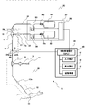
- FIG. 1 shows an overall configuration diagram of a drug solution injector 1a of the first embodiment.
- the chemical liquid injector 1a includes a replacement conduit section 10, a chemical liquid injector 20, a common conduit section 30, and a control device 40.
- the replacement pipeline section 10 and the common pipeline section 30 form a drug solution injection pipeline, and the replacement pipeline section 10 is exchanged for each subject, while the common pipeline section 30 includes a plurality of subjects.
- the replacement pipeline section 10 is an area of a pipeline in which the body fluid of the subject may flow backward
- the common pipeline section 30 is defined as an area in which the body fluid of the subject does not flow backward.
- the chemical liquid injector 1a is configured such that the chemical liquid supplied from the chemical liquid injector 20 first flows into the common conduit section 30, which is a chemical liquid injection conduit, and flows from the common conduit section 30 to the replacement conduit section 10. Is done.
- the replacement pipe section 10 is a line on the subject side, downstream of the common pipe section 30 in the drug solution injection pipe.
- the replacement conduit section 10 is connected at the downstream end to a puncture member 11 such as a needle or a catheter, which is punctured or introduced into the blood vessel of the subject and injects the drug solution into the subject, and has a tubular interior through which the drug solution flows. It has a possible injection tube 12.
- the upstream end is branched into two branches, a first supply tube 16 and a second supply tube 17.
- the first supply tube 16 and the second supply tube 17 are respectively connected to the input side of the mixing device 15, and the mixing supply tube 18 is connected to the output side of the mixing device 15.
- a first connection joint 16a and a second connection joint 17a are connected to the first supply tube 16 and the second supply tube 17 on the side opposite to the side to which the mixing device 15 is connected, respectively.
- the liquid medicine from the first supply tube 16 and the liquid medicine from the second supply tube 17 are mixed by the mixing device 15 and flow into the mixed supply tube 18.
- Both the first supply tube 16, the second supply tube 17, and the mixing supply tube 18 are made of flexible tubes.
- the injection tube 12 can be connected to the mixing supply tube 18 by a connector 12a. Instead of the mixing device 15, it can be connected via a T-shaped connector.
- the replacement conduit section 10 has a T-connector 13 in the mixing supply tube 18, and the T-connector 13 serves as a monitor line 19 for detecting the blood pressure and pulse of the subject from the mixing supply tube 18. Branches.
- a port to which the pressure detector 14 can be connected is disposed at the tip of the monitor line 19, and detects a blood pressure and a pulse of the subject.
- the chemical liquid injector 20 includes a chemical liquid source having an opening, and chemical liquid supply means for compressing the chemical and discharging the chemical from the opening.
- the drug solution injector 20 is typically, for example, a syringe filled with a drug solution.
- the liquid injector 20 serves as a liquid medicine source, and an outer cylinder that can be filled with the liquid medicine, and is inserted into the outer cylinder and moves with respect to the outer cylinder to transfer the liquid medicine.
- a syringe having a piston capable of pressing a chemical solution so as to be pushed out from the opening can be provided.
- the chemical liquid supply means may be a drive motor that applies a driving force for pressing the piston.
- the liquid injector 20 includes a first syringe 21 for supplying a contrast agent as a first liquid, and a second syringe 22 for supplying a physiological saline as a second liquid.
- the first syringe 21 has an outer cylinder 21a, and has an opening 21b at the tip of the outer cylinder 21a for sucking or discharging the first chemical solution, and a piston 21c inserted into an opening opposite to the opening 21b. .
- the second syringe 22 has an outer cylinder 22a, and has an opening 22b for sucking or discharging the second chemical solution at the tip of the outer cylinder 22a, and a piston 22c inserted in an opening opposite to the opening 22b. .
- the chemical liquid injector 20 is provided with a drive motor as a chemical liquid supply means, which applies a driving force for stimulating the movement of the piston of the syringe.
- a first motor 23 and a second motor 24 are provided as drive motors.
- the first motor 23 is connected to the first motor 23 without directly connecting the first motor 23 and the piston 21c and the second motor 24 to the piston 22c.
- the second motor 24 is attached to a piston 21c of the syringe 21 via a pressing member 25, and the second motor 24 is attached to a piston 22c of the second syringe 22 via a pressing member 26.
- the piston 21c of the first syringe 21 and the piston 22c of the second syringe 22 are pushed by the first motor 23 and the second motor 24 via the pressing member 25 and the pressing member 26 to move forward or backward, respectively.
- the piston 21c of the first syringe 21 retreats, the first chemical liquid is sucked into the outer cylinder 21a, and when the piston 21c of the first syringe 21 advances, the first chemical liquid is discharged from the outer cylinder 21a.
- the piston 22c of the second syringe 22 retreats, the second chemical is sucked into the outer cylinder 22a, and when the piston 22c of the second syringe 22 advances, the second chemical is discharged from the outer cylinder 22a.
- the first motor 23 and the second motor 24 are typically, for example, DC motors (DC motors).
- the chemical injector 20 has a control circuit 27, and controls the first motor 23 and the second motor 24, which are drive motors, by pulse width modulation control (PWM control).
- PWM control pulse width modulation control
- the amount of power determined from the pulse width and the voltage on / off duty is added to the drive motor, thereby rotating the drive motor.
- Each of the first motor 23 and the second motor 24 performs a predetermined rotation according to the added electric energy, and based on the rotation angle and the rotation speed, the forward speed, forward amount, and backward movement of the pressing member 25 and the pressing member 26, respectively.
- the speed and the amount of retreat are determined.
- the piston 21c of the first syringe 21 and the piston 22c of the second syringe 22 move with respect to the outer cylinder 21a and the outer cylinder 22a.
- the common conduit section 30 corresponds to the upstream of the replacement conduit section 10 in the chemical liquid injection conduit.
- the common conduit section 30 includes a first chemical liquid line 31 through which a contrast agent as a first chemical liquid flows, and a second chemical liquid line 32 through which a physiological saline as a second chemical liquid flows.
- the downstream side end of the first chemical liquid line 31 is detachably connected to the first connection joint 16 a of the replacement conduit section 10, and is fluidly connectable to the first supply tube 16.
- the downstream side end of the second chemical liquid line 32 is detachably connected to the second connection joint 17 a of the replacement pipeline 10, and can be fluidly connected to the second supply tube 17.
- the first connection joint 16a and the second connection joint 17a are means for joining and separating the replacement pipe section 10 and the common pipe section 30.
- the pipeline of the first chemical solution line 31 is branched by a T-shaped connector 33 on the way, and one of the branched pipelines is connected to the opening 21b of the first syringe 21 and the other stores the first chemical solution.
- the first chemical solution bag 34 is connected via a first chemical solution valve 34a. When the first liquid medicine valve 34a is closed, the first liquid medicine bag 34 and the first liquid medicine line 31 are isolated, and when the first liquid medicine valve 34a is opened, the first liquid medicine bag 34 and the first liquid medicine line 31 communicate.
- the second chemical liquid line 32 is branched in the middle by a T-shaped connector 35, one of which is connected to the opening 22b of the second syringe 22, and the other is a second chemical liquid bag 36 in which the second chemical liquid is stored. Is connected via a second chemical liquid valve 36a.
- the second chemical liquid valve 36a When the second chemical liquid valve 36a is closed, the second chemical liquid bag 36 and the second chemical liquid line 32 are isolated, and when the second chemical liquid valve 36a is opened, the second chemical liquid bag 36 and the second chemical liquid line 32 communicate with each other.
- the first chemical liquid valve 34a and the second chemical liquid valve 36a are not open / close valves, and are respectively connected from the first chemical liquid bag 34 to the first chemical liquid line 31 in a state where the flow from the first chemical liquid line 31 to the first chemical liquid bag 34 is prevented.
- the first liquid medicine bag 34 is always in communication with the first liquid medicine line 31 in a state where only the flow from the first liquid medicine bag 34 to the first liquid medicine line 31 is allowed, and the second liquid medicine bag 36 is connected to the second liquid medicine bag 36.
- the control device 40 includes a central processing unit (CPU) 41, an input device 42, a display device 43, and a storage device 44. Necessary information can be input by the input device 42, and the user can input necessary information as shown on the display device 43. The input information is stored in the storage device 44.
- the control device 40 is electrically connected to the liquid injector 20 by wire or wirelessly.
- the central processing unit (CPU) 41 issues a command to the control circuit 27 of the liquid injector 20 in accordance with the program stored in the storage device 44 and the information stored in the storage device. In this embodiment, an example is shown in which the liquid injector 20 has the control circuit 27, but the liquid injector 20 may not have the control circuit 27. In this case, the control device 40 controls the central processing unit (CPU) 41 to have the function of the control circuit 27, and controls the amount of power added to the first motor 23 and the second motor 24 by the central processing unit (CPU) 41. May be.
- the flow blocking unit 5 is attached to the mixing supply tube 18.
- the flow cutoff unit 5 is attached to the mixing and supply tube 18 in the replacement pipe section 10.
- the flow cutoff unit 5 is mounted in the replacement pipe section 10 or the replacement pipe. What is necessary is just to arrange
- the flow blocking unit 5 may be arranged at the first connection joint 16a and the second connection joint 17a which are the boundary between the replacement pipe section 10 and the common pipe section 30.
- the downstream of the flow blocking unit 5 is a replacement pipe section 10 which is an area of a pipe where the body fluid of the subject may flow backward, and the common pipe section 30 is a flow blocking area where the body fluid of the subject does not flow backward. It is located upstream from the unit 5. That is, in FIG. 1, as an example, the flow blocking unit 5 is described as being located downstream of the mixing device 15, but the positional relationship between the flow blocking unit 5 and the mixing device 15 does not matter.
- the flow blocking unit 5 is opened by the driving force of the driving means 6 to allow the flow of the chemical solution in the mixing and supply tube 18 before and after the mixing and supply tube 18, and the mixing and supply tube 18 and before and after the mixing and supply tube 18.
- the flow shutoff unit 5 is in an open state in which the flow of the chemical solution in the mixing supply tube 18 is allowed before and after the mixing supply tube 18, and shuts off the flow of the chemical solution in the mixing supply tube 18 before and after the mixing supply tube 18.
- the form is not limited, as long as it can be switched between the closed state and the closed state.
- the driving means 6 is electrically connected to the control device 40 by wire or wirelessly.
- the control device 40 can switch the flow shutoff unit 5 between the open state and the closed state according to a command from the central processing unit (CPU) 41. It is possible.
- the flow blocking unit 5 can have, for example, the following forms.
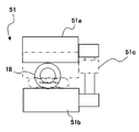
- the flow breaker unit 5 may be, for example, a flow breaker 51 in which the mixing / supply tube 18 is placed between two block members 51a and 51b arranged to face each other.
- FIG. 2A shows a cross-sectional view of an example of the circuit breaker 51.
- the flow breaker 51 has an open state (solid line) in which the block members 51a and 51b are positioned apart from the diameter of the mixing and supply tube 18 to allow the flow in the mixing and supply tube 18, and the block members 51a and 51b mix and supply the flow. It is possible to switch between a closed state (dashed line) in which the flow in the mixing and supply tube 18 is stopped with the mixing and supply tube 18 interposed therebetween with the diameter of the tube 18 approaching.
- the block members 51a and 51b can be moved by the driving means 6 between a distance between an open state (solid line) and a distance between a closed state (dashed line).
- the driving means 6 for supplying a driving force to the block members 51a and 51b various types of driving means 6 can be used as long as the block members 51a and 51b can be moved so that the chemical solution can be cut off in a short time.
- a device that applies a driving force by an electromagnetic force or a device that applies a driving force by a mechanical force such as a liquid pressure or a motor can be used.
- the flow cutoff unit 5 can be an integrated device with the driving means 6, or can be another device.
- a plurality of flow breakers 51 may be arranged on the mixing supply tube 18 along the direction in which the mixing supply tube 18 extends.
- a sequence may be adopted in which the flow shutoff unit 5 is opened in order from the chemical source on the upstream side to the subject on the downstream side.
- a sequence may be adopted in which the flow shutoff unit 5 is sequentially closed from the subject, which is downstream, to the drug solution source, which is upstream.
- the flow shutoff unit 5 may be, for example, a shutoff valve 52 disposed between the flows of the mixing supply tube 18.
- FIG. 2B shows a cross-sectional view of an example of the shut-off valve 52 in the closed state.
- the shutoff valve 52 includes, for example, a first piston 52a and a second piston 52b.
- the first piston 52a and the second piston 52b are received and supported by the valve housing so as to be movable in a direction perpendicular to the flow direction of the mixing and supply tube 18.
- the first piston 52a is provided with a flow path 52c extending along the flow direction of the mixing and supply tube 18, and the second piston 52b is provided with a flow path extending along the flow direction of the mixing and supply tube 18. 52d is drilled.
- the flow of the mixing and supply tube 18 is set such that the first piston 52a is on the downstream side of the chemical injection path, that is, the subject, and the second piston 52b is on the upstream of the chemical injection pipe, that is, the chemical side. Placed between.
- the cross-sectional area of the flow path 52c is smaller than the cross-sectional area of the flow path 52d.
- first piston 52a and the second piston 52b move in the direction perpendicular to the flow path of the mixing and supply tube 18, and the state where the flow paths 52c, 52d, and the flow path of the mixing and supply tube 18 are not aligned is closed.
- State (the state shown in FIG. 2B).
- the first piston 52a and the second piston 52b are movable by the driving means 6 between an open state and a closed state.
- the driving means 6 for supplying a driving force to the first piston 52a and the second piston 52b the first piston 52a and the second piston 52b can be moved so that the chemical solution can be cut off in a short time.
- driving means 6 for supplying a driving force to the first piston 52a and the second piston 52b the first piston 52a and the second piston 52b can be moved so that the chemical solution can be cut off in a short time.
- driving means can be used.
- a device that electromagnetically applies a driving force a device that mechanically applies a driving force such as a liquid pressure or a mechanism can be used.
- the flow cutoff unit 5 can be an integrated device with the driving means 6, or can be another device.
- the shut-off valve 52 driven by the driving unit 6 it is possible to stop the flow of the chemical solution in the mixing supply tube 18 before and after the mixing supply tube 18.
- the shut-off valve in which one or more pistons are arranged can also be applied.
- a plurality of pistons are arranged on the mixing supply tube 18 along the direction in which the mixing supply tube 18 extends.
- a sequence may be employed in which the pistons are sequentially opened from the chemical solution source side, which is upstream, to the subject, which is downstream.
- a sequence may be adopted in which the pistons are sequentially closed from the subject side, which is downstream, to the drug solution source side, which is upstream.
- FIGS. 3A and 3B how the control device 40 drives the flow cutoff unit 5 by the driving means 6 to prevent the backflow of the subject's body fluid in the replacement pipe section 10.
- the point at which the puncture member 11 is pierced into the subject to fill the inside of the first syringe 21 or the second syringe 22 with the drug solution and the injection of the drug solution into the subject is started
- the description will be made assuming that the injection of the drug solution is completed when the drug solution filled in the first syringe 21 or the second syringe 22 is exhausted.
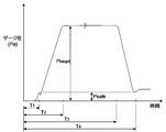
- FIG. 3A shows the history of the pressure in the pipeline at an arbitrary position (D1 in FIG.
- FIG. 3B is a view showing a flowchart of a chemical solution injection process of the chemical solution injection device of the present invention.
- FIG. 3A considering the flow path resistance in the pipeline, the pressure in the pipeline at an arbitrary position (D2 in FIG. 1) of the common pipeline section 30 in FIG. The tendency of the change is almost the same as in FIG. 3A. Further, the pressure inside the first syringe 21 or the second syringe 22 near an arbitrary position (D2 in FIG. 1) of the common conduit section 30 also becomes almost the same as the tendency of the pressure history in FIG. 3A.
- the vertical axis indicates the gauge pressure based on the intravascular pressure of the subject as a zero reference.
- a command is issued from the central processing unit (CPU) 41 of the control device 40 to rotate the first motor 23 and the second motor 24.
- the first motor 23 and the second motor 24 that have received the command advance the piston 21c of the first syringe 21 or the piston 22c of the second syringe 22 in a predetermined sequence.
- the pressure in the drug solution injection conduit including the first syringe 21 or the second syringe 22 gradually increases (S2).
- the pressure in the first syringe 21 or the second syringe 22 has increased to a predetermined pressure (Psafe) higher than the intravascular pressure of the subject when the intravascular pressure of the subject is set as a zero reference. Is determined. If it has not reached, the piston 21c and the piston 22c are advanced, and the pressure in the drug solution injection pipeline including the first syringe 21 or the second syringe 22 is gradually increased (S3).
- the predetermined pressure is on the order of tens of kilopascals [kPa] (several pounds square inches [psi]).
- the predetermined pressure is not limited to this value.
- the pressure of the common pipeline 30 becomes higher than that of the replacement pipeline 10.
- Psafe predetermined pressure
- the control device 40 sends a command to the driving means 6 to open the flow shutoff unit 5 in the closed state. (S4). From this state, the body fluid of the subject does not flow back to the common conduit section 30.
- the chemical rapidly flows into the volume on the downstream side of the flow shutoff unit 5 into which the chemical has not been introduced. It decreases, but soon afterwards the pressure starts to rise. Then, when the pressure reaches the target injection pressure (Ptarget) (time T2 has elapsed), the rotation speeds of the first motor 23 and the second motor 24 are reduced, and the process proceeds to the constant-rate injection of the drug solution. While the drug solution in the first syringe 21 or the second syringe 22 remains sufficiently, the pressure in the drug solution injection pipe shows a pressure history that changes almost constantly depending on the remaining drug solution amount (until time T3). Any time).
- the rotation of the first motor 23 and the second motor 24 is stopped, and the injection of the chemical is completed (S5).
- the injection of the drug solution is left to a natural flow to the subject, and the pressure in the drug solution injection pipe gradually decreases.
- a command is sent to the driving means 6 so that the flow blocking unit 5 is in a closed state in which the flow of the chemical solution is blocked (S7).
- the process (S5) of determining whether or not the predetermined amount of the chemical has been injected may not be particularly provided, and the completion of the injection of the chemical is determined when the predetermined amount of the chemical is injected.
- the control device 40 sends a command to the driving means 6 so that the flow blocking unit 5 is in a closed state in which the flow of the drug solution is shut off (S7). This is often the case in the process of injecting chemicals. In this state, the body fluid of the subject does not flow backward to the upstream of the flow blocking unit 5, that is, at least the most downstream of the common conduit section 30.
- the injection of the chemical is continued (S5).
- the state is abnormal, such as a shortage of the filled chemical solution or leakage of the chemical solution.
- the pressure in the drug solution injection pipeline including the first syringe 21 or the second syringe 22 shows a decreasing pressure history (from the time T3 elapsed to the time T4).
- the control device 40 sends a command to the driving means 6 to open the flow blocking unit 5 in the open state. Is closed.
- the pressure of the common pipeline 30 is higher than that of the replacement pipeline 10. In this state, the body fluid of the subject does not flow backward to the upstream of the flow blocking unit 5, that is, at least the most downstream of the common conduit section 30. The removal of the common pipeline 30 from the replacement pipeline 10 is performed in this state.
- the control device 40 causes the flow blocking unit 5 to be in an open state in which the flow of the drug solution is allowed. Also, when the pressure becomes lower than a predetermined pressure (Psafe), a command is sent to the driving means 6 so that the flow shutoff unit 5 is in a closed state for shutting off the flow of the chemical solution (S7).
- the timing at which the control device 40 sends commands for the step of opening the flow blocking unit 5 to allow the flow of the chemical solution (S3) and the step of closing the flow blocking unit 5 to close the flow of the chemical solution (S7) is as follows.
- human intravascular pressure is at most about 130 millimeters of mercury (897 kilopascals [kPa]) (about 2.51 pound square inches [psi]), and the variation in solids between subjects is at most 30 millimeters of mercury (psi).
- the control device 40 sends a command to open or close the flow shutoff unit 5 to allow the flow of the chemical solution or to shut off the flow.
- the flow interrupting unit 5 is opened after a first predetermined time has elapsed from the start of the drug solution injection.
- a command to close the flow shutoff unit 5 after a predetermined second predetermined time has elapsed after the injection of the drug solution is completed may be sent. Good.
- the first predetermined time is a time in which a predetermined pressure is applied so that the pressure in the common pipeline increases in a state where the flow blocking unit 5 is in a closed state for blocking the flow of the chemical solution. More specifically, during the first predetermined time, the flow shutoff unit 5 is closed as a pressurizing phase that is performed before the actual liquid medicine is injected into the subject from a state in which the liquid medicine is not flown into the pipe at all. In a state where the state is in a state, a small amount of the chemical is flowed at a predetermined injection speed to reach the flow shutoff unit 5, and the pressure in the chemical injection line up to the flow shutoff unit 5 is increased to a predetermined pressure. It is.
- the predetermined predetermined injection speed is, for example, an injection speed lower than the injection speed of the drug solution to the subject.
- the second predetermined time a state in which the pressure in the common conduit portion is high at the same time as the completion of the supply of the chemical from the chemical injector or in a state where the flow blocking unit is closed so as to block the flow of the chemical is ensured. It has been a certain amount of time. Specifically, since the rate of pressure decrease can be predicted for a certain time from the completion of the injection of the drug solution as the second predetermined time, the speed is grasped in advance and assumed after completion of the injection of the drug solution.
- the time is determined based on preliminary measurement performed in advance as a time during which a predetermined pressure (Psafe) higher by several tens of kilopascals [kPa] (several pounds square inches [psi]) than the measured intravascular pressure can be ensured.
- the pressure decreases from here, so that the highest pressure is secured immediately after the completion of the chemical. Therefore, by operating the flow blocking unit 5 by the control device 40 in this way, the body fluid of the subject does not flow backward to the upstream of the flow blocking unit 5, that is, at least the most downstream of the common pipeline 30.
- the flow shutoff unit 5 is the shutoff valve 52 arranged between the flows of the mixing supply tube 18.
- the flow blocking unit 5 is set in a closed state in which the flow path 52c of the first piston 52a and the flow path 52d of the second piston 52b do not communicate with each other, and the flow of the chemical solution is blocked. This state is before the start of the injection of the chemical solution in which the chemical solution has not flowed and has not reached the shutoff unit 5.
- a pressurization phase in which the flow shutoff unit 5 is maintained in a closed state, and a small amount of a chemical solution is flowed to the flow shutoff unit 5 at a predetermined injection rate is executed.
- the predetermined predetermined injection speed is, for example, an injection speed lower than the injection speed of the drug solution to the subject.
- a chemical solution of 0.3 ml is flowed at a speed of 2 ml per second for 150 milliseconds so that the chemical solution reaches the flow blocking unit 5.
- the flow shutoff unit 5 is shifted to the open state. 10 milliseconds after this corresponds to the first predetermined time.
- the flow blocking unit 5 is opened to allow the flow of the chemical.
- the flow path 52d of the second piston 52b on the upstream side is opened, and then the flow path 52c of the first piston 52a on the downstream side is opened. That is, in this sequence in which two or more pistons are used as the shutoff valve 52, the pistons are opened from the upstream side, so that the flow shutoff unit 5 is completely opened with the most downstream piston opened. .
- the first motor 23 and the second motor 24 are first stopped after the injection is completed.
- the flow shutoff unit 5 is closed. That is, first, the first motor 23 and the second motor 24 are stopped at the same time or after a certain time has elapsed. In general, for example, the passage 52c of the first piston 52a on the downstream side is closed after a lapse of several milliseconds to several seconds as a fixed time after the first motor 23 and the second motor 24 are stopped. Subsequently, the flow path 52d of the second piston 52b on the upstream side is closed, and the flow blocking unit 5 is closed.
- shutoff valve 52 uses two or more pistons
- the pistons are closed from the downstream side, so that the flow shutoff unit 5 is completely closed with the most upstream piston open.
- the timing of closing the pistons has been described as an example, but the timing of opening all the pistons simultaneously or using the timing of simultaneously closing the pistons is used. May be.
- a shut-off valve 52 having a first piston 52a and a second piston 52b will be described as an example having two or more pistons constituting the shut-off valve 52.
- the second piston 52b on the upstream side is used.
- the cross-sectional area of the flow path 52d is set larger than the cross-sectional area of the flow path 52c of the first piston 52a. Therefore, when the first piston 52a and the second piston 52b are simultaneously driven, first the upstream side The flow path 52d of the second piston 52b communicates, and subsequently the flow path 52c of the downstream first piston 52a communicates thereafter. On the other hand, conversely, after the injection of the drug solution, after a certain time has elapsed after the injection is completed and the first motor 23 and the second motor 24 are stopped, the first piston 52a and the second piston 52b are simultaneously driven.
- the flow path 52c of the first piston 52a on the downstream side is closed, and then the flow path 52d of the second piston 52b on the upstream side is closed to close the flow shutoff unit 5. That is, by adjusting the operation timings of the first piston 52a and the second piston 52b, and the cross-sectional area of the flow path 52c of the first piston 52a and the cross-sectional area of the flow path 52d of the second piston 52b, as described above, When the shut-off valve 52 is opened, the flow path is made to communicate from the upstream side to the downstream side of the piston constituting the shut-off valve 52 in order.
- the flow path may be closed in order from the downstream side to the upstream side of the piston constituting the valve 52.
- the method does not measure the pressure at all and uniquely assumes the intravascular pressure of a human as a predetermined value, but directly measures the intravascular pressure of the human with a pressure sensor or the like to make a determination. be able to.
- the pressure detector 14 may be arranged at the port of the monitor line 19 for detecting the blood pressure and the pulse of the subject to measure the intravascular pressure of the subject. That is, the pressure detector 14 is arranged at an arbitrary position in one of the replacement pipeline 10 and the common pipeline 30.
- any type of pressure sensor can be used as the pressure detector 14, and a typical example is a pressure sensor such as a semiconductor pressure sensor or a piezoelectric element.
- a typical example is a pressure sensor such as a semiconductor pressure sensor or a piezoelectric element.
- the pressure detector 14 may be disposed near the inside of the first syringe 21 or the second syringe 22 to directly measure the pressure.
- a predetermined pressure (Psafe) is determined based on the electric signal output from the pressure detector 14, and based on the detection of the electric signal corresponding to the predetermined pressure (Psafe) by the pressure detector 14, the control device 40 executes the flow shutoff unit. It is also possible to send a command to set 5 to an open state that allows the flow of the chemical solution or a closed state to shut off.
- control device 40 sets the flow blocking unit 5 to an open state allowing the flow of the chemical solution (S3), and the control device 40 sets the flow blocking unit 5 to a closed state to block the flow of the chemical solution (S7).
- the predetermined pressure may be determined according to a value corresponding to the amount of power input to the drive motor to drive the first motor 23 and the second motor 24 that are the drive motors.
- the value corresponding to the amount of power input to the drive motor is the amount of power input to the drive motor in the case of PWM control using a constant voltage pulse.
- the value corresponding to the electric energy input to the drive motor includes the value of the current input to the drive motor.
- a relationship between a value corresponding to the amount of electric power input to each of the first motor 23 and the second motor 24 and the pressure in the chemical injection pipe is acquired in advance as data.
- Each of the rotation speed and rotation angle of the first motor 23 and the second motor 24 is an electric signal having a value (including a value corresponding to a current) corresponding to the amount of power output from the central processing unit 41 of the control device 40.
- the first motor 23 and the second motor 24 which have been instructed by the control device 40, operate the piston 21c or the second syringe 22 of the first syringe 21 in a predetermined sequence.
- the piston 22c is advanced.
- the central processing unit 41 of the control device 40 is configured to drive the first motor 23 and the second motor 24 when driving the electric signals (input to the drive motor) to the first motor 23 and the second motor 24. From the electric signal corresponding to the electric energy or the electric current), the pressure in the chemical liquid injection pipe is determined as shown in FIG. 3A.
- the control device 40 sends a command to the driving means 6 to open the flow blocking unit 5 in the closed state. In this state, the body fluid of the subject does not flow backward to the upstream of the flow blocking unit 5, that is, at least the most downstream of the common conduit section 30.
- the control device 40 drives the driving means.
- a command is sent to 6 to close the flow shutoff unit 5 in the open state.
- the pressure of the common pipeline 30 becomes higher than that of the replacement pipeline 10. In this state, the body fluid of the subject does not flow back to the common conduit section 30. The removal of the common pipeline 30 from the replacement pipeline 10 can be performed in this state.
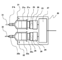
- FIG. 4 shows a part of the liquid injector 20 shown in FIG.
- a pressing force detector is arranged on a pressing member that directly presses a piston of a syringe.
- a pressing force detector for example, a load cell is used as a simple device.
- a strain gauge is attached to a pressing member, and a pressing force is detected based on an electric signal output based on the amount of strain of the pressing member. Includes strain gauges that measure pressure indirectly.
- the pressing force by which the motor presses the piston can be obtained from the electric signal output by the pressing force detector when the motor presses the pressing member.
- the correspondence between the electric signal output from the pressing force detector when the motor presses the piston and the pressure in the drug solution injection pipe including the syringe is measured in advance. This correspondence corresponds to the correspondence between the pressing force by which the motor presses the piston and the pressure in the drug solution injection conduit including the syringe.
- the pressure in the chemical liquid injection conduit including the syringe is determined based on the electric signal output from the pressing force detector. That is, when the pressing force detector is used as a load cell, the following is performed.
- the load cell 28 and the load cell 29 are attached.
- the relationship between the electric signal output from the load cell 28 and the pressure in the chemical injection pipe is acquired in advance, and the corresponding data is stored in the storage device 44.
- the pressure in the chemical injection line is determined based on the electric signal. Specifically, first, when the flow cutoff unit 5 is in the closed state, the first motor 23 and the second motor 24, which have been commanded by the control device 40, perform predetermined operations via the pressing members 25 and 26.
- the piston 21c of the first syringe 21 and the piston 22c of the second syringe 22 are pressed and moved in the outer cylinder 21a and the outer cylinder 22a, respectively.
- the load cells 28 and 29 respond to the pressing force of the first motor 23 pressing the piston 21c of the first syringe 21 and the pressing force of the second motor 24 pressing the piston 22c of the second syringe 22. And output an electric signal. From this electric signal, the pressure in the chemical injection line is determined as shown in FIG. 3A.
- Judgment is made from the electric signals output from the load cell 28 and the load cell 29, and when the electric signal reaches a value corresponding to a predetermined pressure (Psafe) (time T1 elapses), the electric signal becomes common.
- Psafe a predetermined pressure
- the pressure in the pipe section 30 becomes higher than that in the replacement pipe section 10 side. Therefore, the control device 40 sends a command to the driving means 6 to open the flow blocking unit 5 in the closed state. In this state, the body fluid of the subject does not flow backward to the upstream of the flow blocking unit 5, that is, at least the most downstream of the common conduit section 30.
- the medical fluid injector 20 can also adopt an aspect other than a syringe.
- a second embodiment of the present invention other than the syringe will be described with reference to FIG.
- the second embodiment is a type of the embodiment in which a pressurizing device that pressurizes the inside of a container holding a chemical solution and discharges the chemical solution is used as a chemical solution supply unit.
- FIG. 5 shows an overall configuration diagram of a drug solution injector 1b of the second embodiment.
- the chemical liquid injector 1b is the same as the first embodiment in that the chemical liquid injector 1b includes a replacement conduit section 10, a chemical liquid injector 20, a common conduit section 30, and a control device 40.
- the chemical supplied from 20 first flows into the common conduit 30 which is the chemical injection conduit, and then flows from the common conduit 30 to the replacement conduit 10.
- the replacement pipeline section 10 and the common pipeline section 30 form a drug solution injection pipeline, and the replacement pipeline section 10 is exchanged for each subject. Is commonly used by a plurality of subjects.
- the differences between the second embodiment and the first embodiment will be described. Otherwise, the configuration of the first embodiment can be applied as it is.
- the liquid injector 20 is in the form of a syringe, but in the second embodiment, the liquid source of the liquid injector 20 is for supplying a contrast agent as the first liquid.
- a first container 61 and a second container 62 for supplying a physiological saline as a second chemical solution.
- Each of the first container 61 and the second container 62 may be a hard resin container or a flexible bag-shaped resin container. The material does not matter.
- the chemical solution supply means of the chemical solution injector 20 is a first pressure pump 63 and a second pressure pump 64 for pressurizing the first container 61 and the second container 62, respectively.
- the control circuit 27 is the same as in the first embodiment, and the first pressure pump 63 and the second pressure pump 64 are controlled by the control circuit 27.
- the first pressurizing pump 63 and the second pressurizing pump 64 connect the first chemical solution in the first container 61 and the second container through the pressurizing port 61a of the first container 61 and the pressurizing port 62a of the second container 62.
- the second chemical solution in 62 is pressurized.
- the configuration of the replacement pipe section 10 and the control device 40 is the same as in the first embodiment.
- the configuration of the common conduit section 30 is almost the same as that of the first embodiment, except that the first chemical liquid bag 34 is not connected to the conduit of the first chemical liquid line 31 and the second chemical liquid line 32 is connected to the conduit of the second chemical liquid line 32.
- the difference from the first embodiment is that the two drug solution bags 36 are not connected.
- the other points are the same as those of the first embodiment, including the point that a first chemical liquid line 31 through which a contrast agent as a first chemical liquid flows and a second chemical liquid line 32 through which a physiological saline as a second chemical liquid flows.
- the opening 61b in the first container 61 is fluidly connected to the first chemical liquid line 31, and the opening 62b in the second container 62 is fluidly connected to the second chemical liquid line 32.
- the control for the operation of the first pressure pump 63 and the second pressure pump 64 by the control device 40 is the same as in the first embodiment. That is, the first pressurizing pump 63 and the second pressurizing pump 64 receiving the command from the control device 40 pressurize the first container 61 and the second container 62 in a predetermined sequence.
- the central processing unit 41 of the control device 40 drives the first pressurizing pump 63 and the second pressurizing pump 64, the electric power input to the first pressurizing pump 63 and the second pressurizing pump 64 is controlled.
- the pressure in the chemical solution injection pipe is determined as in FIG. 3A as in the first embodiment.
- the electric signal input to the first pressurizing pump 63 and the second pressurizing pump 64 reaches a value at which the pressure in the chemical solution injection pipe reaches a value corresponding to a predetermined pressure (Psafe) (time T1 has passed)
- Psafe predetermined pressure
- the pressure of the common pipeline 30 is higher than that of the replacement pipeline 10. Therefore, the control device 40 sends a command to the driving means 6 to open the flow blocking unit 5 in the closed state. In this state, the body fluid of the subject does not flow backward to the upstream of the flow blocking unit 5, that is, at least the most downstream of the common conduit section 30.
- FIG. 6 is an overall configuration diagram of a drug solution injector 1c according to the third embodiment.
- the chemical liquid injector 1c is the same as the first embodiment in that the liquid injector 1c includes a replacement pipeline 10, a chemical injector 20, a common conduit 30, and a controller 40. This is the same in that the chemical supplied from 20 first flows into the common conduit 30 which is the chemical injection conduit, and then flows from the common conduit 30 to the replacement conduit 10. Also in the third embodiment, the replacement pipeline section 10 and the common pipeline section 30 form a drug solution injection pipeline, and the replacement pipeline section 10 is exchanged for each subject. Is commonly used by a plurality of subjects. Hereinafter, points of the third embodiment that are different from the second embodiment will be described. Otherwise, the configuration of the second embodiment can be applied as it is.
- the chemical liquid supply means is not a pressure pump but a pressure means for pressing the container to apply pressure.
- the inside of the container of the chemical liquid source is pressurized so that the chemical liquid first flows into the common conduit section 30 which is the chemical liquid injection conduit, and flows from the common conduit section 30 to the replacement conduit section 10. Configured.
- the container of the liquid medicine source is pressurized from the outside, and the liquid medicine is first poured into the common pipe line section 30 which is the liquid medicine injection pipe, and from the common pipe line section 30 to the replacement pipe line section 10. It is configured to flow.
- the liquid medicine source of the liquid medicine injector 20 is a first container 71 for supplying a contrast agent as a first liquid medicine and a second container for supplying a physiological saline as a second liquid medicine. 72.
- Each of the first container 71 and the second container 72 is typically a flexible bag-shaped container, typically a resin bag, but the material is not limited.
- the chemical solution supply means of the chemical solution injector 20 includes a first pressure body 73 and a second pressure body 74 which are pressure means for pressurizing the first container 71 and the second container 72, respectively. is there.
- the first pressure member 73 and the second pressure member 74 are roller-shaped members driven by power such as a motor, and press the flexible first container 71 and second container 72.
- the first container 71 and the second container 72 are crushed while moving in the directions of the openings 71a and 72a.
- the control circuit 27 is the same as that of the first embodiment, and the first pressure member 73 and the second pressure member 74 are controlled by the control circuit 27.
- first pressurizing member 73 and the second pressurizing member 74 increase the internal pressure of a compressible fluid such as air sealed in a flexible bag-shaped container capable of changing volume, thereby changing the volume of the first container. It is also possible to press and compress the 71 and the second container 72 to increase the pressure of the chemical solution inside.
- the configuration of the replacement pipe section 10 and the control device 40 is the same as in the first embodiment.
- the configuration of the common conduit section 30 is almost the same as that of the first embodiment, except that the first chemical liquid bag 34 is not connected to the conduit of the first chemical liquid line 31 and the second chemical liquid line 32 is connected to the conduit of the second chemical liquid line 32.
- the difference from the first embodiment is that the two drug solution bags 36 are not connected.
- the other points are the same as those of the first embodiment, including the point that a first chemical liquid line 31 through which a contrast agent as a first chemical liquid flows and a second chemical liquid line 32 through which a physiological saline as a second chemical liquid flows.
- the opening 71a in the first container 71 is fluidly connected to the first chemical liquid line 31, and the opening 72a in the second container 72 is fluidly connected to the second chemical liquid line 32.
- the control for the operation of the first pressure member 73 and the second pressure member 74 by the control device 40 is the same as in the first embodiment. That is, the first pressurizing member 73 and the second pressurizing member 74 that have received the instruction from the control device 40 press the first container 71 and the second container 72 in a predetermined sequence.
- the central processing unit 41 of the control device 40 controls the electric power input to the first and second pressurizing members 73 and 74 when driving the first and second pressurizing members 73 and 74.
- the pressure in the chemical solution injection pipe is determined as in FIG.
- the electric signal input to the first pressurizing body 73 and the second pressurizing body 74 reaches a value at which the pressure in the chemical injection pipe reaches a value corresponding to a predetermined pressure (Psafe) (time T1 has passed)
- Psafe predetermined pressure
- the pressure of the common pipeline 30 is higher than that of the replacement pipeline 10. Therefore, the control device 40 sends a command to the driving means 6 to open the flow blocking unit 5 in the closed state. In this state, the body fluid of the subject does not flow backward to the upstream of the flow blocking unit 5, that is, at least the most downstream of the common conduit section 30.
- each of the first pressing member 73 and the second pressing member 74 may be a pressure winding member 75 as shown in FIG. 7B. That is, in the modification of the third embodiment, each of the first container 71 and the second container 72 is typically a flexible bag-shaped container, and is typically a resin bag. The material does not matter.
- the chemical liquid supply means of the chemical liquid injector 20 is a pressure winding body 75 that pressurizes the first container 71 and the second container 72, respectively. The pressure take-up body 75 advances while squeezing the first container 71 and the second container 72 in the direction of the opening 71a and the opening 72a while winding the flexible first container 71 and the second container 72.
- the control circuit 27 is the same as that of the first embodiment, and the pressure take-up body 75 is controlled by the control circuit 27.
- the pressure of the chemical solution in the first container 71 and the second container 72 is increased from the outside in the first container 71 and the second container 72 by the pressure take-up body 75, and the pressure of the first chemical solution in the first container 71 is increased.
- the second chemical solution in the second container 72 flows. Then, when the electric signal input from the control device 40 to the pressurizing take-up body 75 reaches a value corresponding to a predetermined pressure (Psafe) in the chemical liquid injection pipe (time T1), the common pipe The pressure of the passage 30 is higher than that of the replacement conduit 10.
- Psafe predetermined pressure
- the control device 40 sends a command to the driving means 6 to open the flow blocking unit 5 in the closed state.
- the body fluid of the subject does not flow back to the common conduit section 30.
- the control device 40 causes the driving means 6 to operate.
- Psafe predetermined pressure
- the control device 40 causes the driving means 6 to operate.
- the pressure of the common pipeline 30 becomes higher than that of the replacement pipeline 10.
- the body fluid of the subject does not flow back to the common conduit section 30.
- the removal of the common pipeline 30 from the replacement pipeline 10 can be performed in this state.
- FIG. 8 shows an overall configuration diagram of a liquid injector 1d of the fourth embodiment.
- the chemical liquid injector 1d is the same as the first embodiment in that the chemical liquid injector 1d includes a replacement pipe section 10, a chemical liquid injector 20, a common conduit section 30, and a control device 40. This is the same in that the chemical supplied from 20 first flows into the common conduit 30 which is the chemical injection conduit, and then flows from the common conduit 30 to the replacement conduit 10.
- the replacement pipeline section 10 and the common pipeline section 30 form a drug solution injection pipeline, and the replacement pipeline section 10 is exchanged for each subject. Is commonly used by a plurality of subjects.
- a roller pump 83 and a roller pump 84 are used as the liquid supply means. Otherwise, the configuration of the third embodiment can be applied as it is.
- the chemical liquid injector 20 includes a chemical liquid supply source and a pump.
- the liquid medicine sources of the liquid medicine injector 20 are a first container 81 for supplying a contrast agent as a first liquid medicine and a second container 82 for supplying a physiological saline as a second liquid medicine.
- the pump any type of pump can be used as long as the pump has a structure in which the pressure in the downstream pipe is reduced while being pressed, and the chemical solution in the upstream pipe is pumped to the downstream pipe. Applicable.
- Typical examples of this type of pump are a roller pump and a finger pump.
- the roller pump 83 and the roller pump 84 will be described as an example.
- Each of the first container 81 and the second container 82 may be a hard resin container or a flexible bag-shaped resin container. The material does not matter.
- the roller pump 83 and the roller pump 84 are respectively connected to the conduit of the first chemical liquid line 31 joined to the opening 81a of the first container 81 of the common conduit section 30 and the second conduit 82 joined to the opening 82a of the second container 82.
- the two chemical liquid lines 32 are disposed in the pipeline.
- the roller pump 83 and the roller pump 84 may be mounted anywhere in the chemical liquid conduit of the common conduit unit 30 as long as the roller pump 83 and the roller pump 84 are located upstream of the flow blocking unit 5. It may be attached to the mixing supply tube 18.
- the two chemical liquid lines 32 are fixedly disposed so as to be wound around the rotating body 85.
- FIG. 9 is a functional configuration diagram in which the roller pump 83 is enlarged. Since the roller pump 84 has the same configuration, the description of the roller pump 83 will be replaced with the description of the roller pump 84.
- the roller pump 83 has a rotating body 85.
- the rotator 85 is rotatable around the rotation center of the rotator.
- At least two pressing portions 85a and 85b, which are projections, are provided on a circumference centered on the rotation center of the rotating body 85 so that the arc distance is equal. That is, the two pressing portions 85a and 85b are arranged at a central angle of 180 degrees on a circumference centered on the rotation center of the rotating body 85. For example, when three pressing parts are arranged, they are arranged at a central angle of 120 degrees, and when four pressing parts are arranged, they are arranged at a central angle of 90 degrees.
- the pressing portions 85a and 85b of the two projections respectively crush the conduit of the first chemical liquid line 31.
- the conduit of the first chemical liquid line 31 is narrowed, and the liquid medicine can enter between the pressing part 85a and the pressing part 85b.
- the section 31b is made. On both sides of the section 31b, an upstream section 31a and a downstream section 31c are completed. In this state, for example, when the rotating body 85 is rotated clockwise in FIG. 9 (in the direction of the arrow in FIG. 9), the pressing portion 85a moves on the section 31b while pressing the conduit of the first chemical liquid line 31.
- the pressing portion 85b pushes the pipeline of the first chemical liquid line 31 so that the pressing portion 85b pumps the chemical in the pipeline of the first chemical liquid line 31 above the section 31b.
- the chemical solution moves to the downstream section 31c.
- the chemicals in the first container 81 and the second container 82 are supplied to the pipeline of the first chemical liquid line 31 and the second chemical liquid line 32, and It is supplied from the path section 30 to the replacement pipe section 10.
- the other points are the same as those of the first embodiment, including the point that a first chemical liquid line 31 through which a contrast agent as a first chemical liquid flows and a second chemical liquid line 32 through which a physiological saline as a second chemical liquid flows.
- the control for the operation of the roller pump 83 and the roller pump 84 by the control device 40 is the same as in the first embodiment. That is, the roller pump 83 and the roller pump 84 that have received the instruction from the control device 40 perform a predetermined sequence between the pressing portion 85a and the pressing portion 85b between the pipeline of the first chemical liquid line 31 and the second chemical liquid line 32. The pressure in the pipeline corresponding to the section 31b is reduced.
- the central processing unit 41 of the control device 40 drives the roller pump 83 and the roller pump 84
- the central processing unit 41 outputs electric signals (input to the roller pump 83 and the roller pump 84) that are input to the roller pump 83 and the roller pump 84.
- the pressure in the chemical solution injection pipe is determined as shown in FIG. 3A as in the first embodiment.
- the electric signal input to the roller pump 83 and the roller pump 84 reaches the value (time T1 elapses) when the pressure in the chemical liquid injection pipe reaches a value corresponding to the predetermined pressure (Psafe)
- the common pipe section 30 The pressure becomes higher than that of the replacement pipe section 10. Therefore, the control device 40 sends a command to the driving means 6 to open the flow blocking unit 5 in the closed state. In this state, the body fluid of the subject does not flow backward to the upstream of the flow blocking unit 5, that is, at least the most downstream of the common conduit section 30.
- FIG. 10 shows a flowchart of a sequence for refilling the first syringe 21 or the second syringe 22 with the chemical solution.
- the control device 40 Since the pressure in the chemical injection line has decreased to a predetermined pressure (Psafe), the control device 40 is instructed to close the flow cutoff unit 5, and the flow cutoff unit 5 is closed. (S7 in FIG. 3B).
- This embodiment proceeds after this step. First, it is confirmed that the flow blocking unit 5 is in the closed state, and the flow blocking unit 5 is maintained in the closed state (S11). Subsequently, the first chemical liquid valve 34a is opened to communicate the first chemical liquid bag 34 with the first chemical liquid line 31, and the second chemical liquid valve 36a is opened to communicate the second chemical liquid bag 36 with the second chemical liquid line 32 (S12). ).
- the process of opening the first chemical liquid valve 34a and the second chemical liquid valve 36a becomes unnecessary. Since the shutoff unit 5 is closed, the first chemical solution bag 34 flows toward the first syringe 21 via the first chemical solution line 31 in each of the first chemical solution line 31 and the second chemical solution line 32, The two chemical liquid bags 36 have a pressure gradient that can flow toward the second syringe 22 via the second chemical liquid line 32. In this state, a command is issued from the central processing unit (CPU) 41 of the control device 40 to rotate the first motor 23 and the second motor 24 in reverse. The first motor 23 and the second motor 24 that have received the command retract the piston 21c of the first syringe 21 or the piston 22c of the second syringe 22 in a predetermined sequence.
- CPU central processing unit
- the pressure in the liquid medicine injection conduit including the first syringe 21 or the second syringe 22 gradually decreases, and the first liquid medicine flows from the first liquid medicine line 31 to the first syringe 21 and the second liquid medicine flows into the second syringe 21.
- the liquid is sucked into the second syringe 22 of the chemical liquid line 32 (S13). It is determined whether a predetermined amount of the first chemical solution has been filled in the first syringe 21 with a predetermined amount of the second chemical solution, and if the second syringe 22 has not been filled yet, the filling is further continued.
- the filling is completed (S14). If the first syringe 21 has been filled with a predetermined amount of the second solution in the first syringe 21, the first solution valve 34 a is closed and the first solution bag 34 is moved to the first solution when the filling is completed.
- the second chemical solution valve 36a is closed from the line 31, and the second chemical solution bag 36 is isolated from the second chemical solution line 32 (S15). If the first chemical liquid valve 34a and the second chemical liquid valve 36a are not one-way valves but one-way valves, the process of closing the first chemical liquid valve 34a and the second chemical liquid valve 36a (S15) becomes unnecessary.
- the pressure of the pipeline is locally (for example, D2 in FIG. 1) within the pipeline of the common pipeline 30. May be lower than the intravascular pressure of the subject, and the body fluid of the subject may flow back to the common conduit 30.
- the first syringe 21 is filled with a predetermined amount of the first solution into the first syringe 21 and the second syringe 22 is filled with the second solution by a predetermined amount. It is necessary to pressurize to a higher predetermined pressure (Psafe). Then, a command is issued from the central processing unit (CPU) 41 of the control device 40 to the first motor 23 and the second motor 24 to rotate forward.
- CPU central processing unit
- the first motor 23 and the second motor 24 that have received the command advance the piston 21c of the first syringe 21 or the piston 22c of the second syringe 22 in a predetermined sequence, and a predetermined pressure higher than the intravascular pressure of the subject.
- the pressure is increased to the pressure (Psafe) (S16).
- the control device 40 in the first embodiment sets the flow blocking unit 5 to an open state that allows the flow of the drug solution (S3).
- the timing of sending the command of the step (S7) of closing the flow blocking unit 5 to close the flow of the chemical solution (S7) the pressure in the chemical solution injection pipe may be actually measured, or the chemical solution injection may be performed.
- a technique that does not directly measure the pressure in the pipeline can be adopted as it is.
- the pressure of the common conduit 30 is higher than that of the replacement conduit 10, and the body fluid of the subject does not flow back to the common conduit 30. From here, it is possible to restart the sequence from S1 in FIG. 3B.
Landscapes
- Health & Medical Sciences (AREA)
- Biomedical Technology (AREA)
- Hematology (AREA)
- Vascular Medicine (AREA)
- Engineering & Computer Science (AREA)
- Anesthesiology (AREA)
- Veterinary Medicine (AREA)
- Heart & Thoracic Surgery (AREA)
- Public Health (AREA)
- Life Sciences & Earth Sciences (AREA)
- Animal Behavior & Ethology (AREA)
- General Health & Medical Sciences (AREA)
- Fluid Mechanics (AREA)
- Physics & Mathematics (AREA)
- Infusion, Injection, And Reservoir Apparatuses (AREA)
Abstract
Description
続いて、この実施の形態について、以下、それぞれの具体的な実施例として説明する。
以下、まず本願発明の第1実施例について図1から図4を参照して説明する。第1実施例は、実施の形態のうち、シリンジを採用したタイプである。図1は、第1実施例の薬液注入装置1aの全体構成図を示している。薬液注入装置1aは、取替管路部10と、薬液注入器20と、共通管路部30と、制御装置40と、を備えている。取替管路部10と、共通管路部30とが薬液注入管路を形成し、取替管路部10は被検者ごとに交換され、一方共通管路部30は複数の被検者に共通的に使用されるものである。取替管路部10は被検者の体液が逆流する可能性がある管路の領域であり、共通管路部30は被検者の体液が逆流しない領域として区別して定義する。薬液注入装置1aでは、薬液注入器20から供給された薬液が、薬液注入管路である共通管路部30にまず流れ込み、共通管路部30から取替管路部10へと流れるように構成される。
第2所定時間は、前記薬液注入器から薬液の供給の完了と同時または前記流れ遮断ユニットを前記薬液の流れを遮断する閉状態とした状態で前記共通管路部内の圧力が高い状態が確保された一定の時間である。具体的には、第2所定時間としての薬液の注入の完了からの一定の時間は、圧力の減少速度が予測できることから、予めその速度を把握しておき、薬液の注入を完了した後から仮定した血管内圧力より数十キロパスカル[kPa](数ポンド平方インチ[psi])程度高い所定の圧力(Psafe)となることが確保できる時間として予め実施する予備計測に基づいて定められる。また、薬液の注入の完了と同時の場合には、薬液が完了した直後では、血管内圧力より数十キロパスカル[kPa](数ポンド平方インチ[psi])程度高い所定の圧力(Psafe)となっていることが確保されている。薬液の注入後はここから圧力が減少するから薬液が完了した直後が最も高い圧力が確保されていることになる。したがって、このように制御装置40により流れ遮断ユニット5を動作させることで、流れ遮断ユニット5の上流、すなわち少なくとも共通管路部30の最も下流まで被検者の体液が逆流することはない。
薬液注入器20は、シリンジ以外の態様も採用できる。以下、薬液注入器20として、シリンジ以外の態様の第2実施例について図5を参照して説明する。第2実施例は、実施の形態のうち、薬液を保持した容器の内部を加圧して薬液の吐出を行なう加圧装置を薬液供給手段として使用したタイプである。図5は、第2実施例の薬液注入装置1bの全体構成図を示している。薬液注入装置1bは、取替管路部10と、薬液注入器20と、共通管路部30と、制御装置40と、を備えている点で第1実施例と同じであり、薬液注入器20から供給された薬液が、薬液注入管路である共通管路部30にまず流れ込み、共通管路部30から取替管路部10へと流れるように構成される点も同じである。第2実施例でも、取替管路部10と、共通管路部30とが薬液注入管路を形成し、取替管路部10は被検者ごとに交換され、一方共通管路部30は複数の被検者に共通的に使用されるものである。以下、第2実施例について、第1実施例と異なる点について説明する。それ以外は、第1実施例の構成がそのまま適用可能である。
薬液注入器20の第1容器61と第2容器62とを可撓性のあるバッグ状の樹脂容器とした場合には以下の態様も採用できる。以下、第3実施例について図6と図7Aおよび図7Bとを参照して説明する。第3実施例は、実施の形態のうち、薬液を保持した容器の外部を押圧することにより容器内を加圧して薬液の前記吐出を行なう加圧装置を薬液供給手段として使用したタイプである。第3実施例は第2実施例を変更させたものである。図6は、第3実施例の薬液注入装置1cの全体構成図を示している。薬液注入装置1cは、取替管路部10と、薬液注入器20と、共通管路部30と、制御装置40と、を備えている点で第1実施例と同じであり、薬液注入器20から供給された薬液が、薬液注入管路である共通管路部30にまず流れ込み、共通管路部30から取替管路部10へと流れるように構成される点も同じである。第3実施例でも、取替管路部10と、共通管路部30とが薬液注入管路を形成し、取替管路部10は被検者ごとに交換され、一方共通管路部30は複数の被検者に共通的に使用されるものである。以下、第3実施例について、第2実施例と異なる点について説明する。それ以外は、第2実施例の構成がそのまま適用可能である。
続いて、第4実施例について図8と図9とを参照して説明する。第4実施例は、実施の形態のうち、下流側の管路を減圧して薬液を圧送するタイプである。図8は、第4実施例の薬液注入装置1dの全体構成図を示している。薬液注入装置1dは、取替管路部10と、薬液注入器20と、共通管路部30と、制御装置40と、を備えている点で第1実施例と同じであり、薬液注入器20から供給された薬液が、薬液注入管路である共通管路部30にまず流れ込み、共通管路部30から取替管路部10へと流れるように構成される点も同じである。第4実施例でも、取替管路部10と、共通管路部30とが薬液注入管路を形成し、取替管路部10は被検者ごとに交換され、一方共通管路部30は複数の被検者に共通的に使用されるものである。以下、第4実施例について、第3実施例と異なる点について説明する。第4実施例の薬液注入装置1dでは、薬液供給手段としてローラポンプ83とローラポンプ84とを使用したものである。それ以外は、第3実施例の構成がそのまま適用可能である。
次に、本発明の別の実施形態について説明する。ここで説明する実施の形態では、前述の本発明の実施の形態の第1実施例の薬液注入装置1aと同じ構成である。この実施の形態では、図3Bのフローチャートにおいて、所定量の薬液が未だ注入されていない段階であるが、薬液の注入が完了する前に薬液注入管路内の圧力が所定の圧力(Psafe)になり(時間T4経過時点)で流れ遮断ユニット5が閉状態にされた後のシーケンスである。すなわち、所定量の薬液が未だ注入されていないので、第1シリンジ21に第1薬液を、第2シリンジ22に第2薬液を再充填するシーケンスである。図10を参照して、この実施の形態について説明する。ここでは、前述の本発明の実施の形態の第1実施例の装置の構成をそのまま参照して説明する。図10は、第1シリンジ21または第2シリンジ22に、薬液を再充填するシーケンスのフローチャートを示している。
5 流れ遮断ユニット
6 駆動手段
10 取替管路部
11 穿刺部材
12 注入チューブ
15 ミキシングデバイス
18 混合供給チューブ
20 薬液注入器
23,24 駆動モータ
25,26 押圧部材
27 制御回路
28,29 ロードセル
30 共通管路部
40 制御装置
41 中央処理装置
61,71 第1容器
62,72 第2容器
73 第1加圧体
74 第2加圧体
83,84 ローラポンプ
85 回転体
Claims (15)
- 薬液を被検者に注入するための薬液注入装置であって、
開口を有する前記薬液の薬液源と、前記開口から前記薬液の吐出を行なう薬液供給手段とを備える薬液注入器と、
前記被検者の血管へと前記薬液を供給する取替管路部と、
前記薬液源の前記開口と接続され前記薬液を前記薬液注入器から前記取替管路部へと前記薬液を流す共通管路部と、
前記薬液供給手段と有線または無線により電気的に接続されて前記薬液供給手段の駆動を制御する制御装置と、
前記取替管路部内または前記取替管路部と前記共通管路部との境界部の管路に配置され、前記制御装置と有線または無線により電気的に接続される前記薬液供給手段が前記制御装置より指令を受けることにより、前記薬液の流れを許容する開状態と、前記薬液の流れを遮断する閉状態との間を切り替え可能な流れ遮断ユニットとを備え、
前記制御装置は、前記薬液注入器から薬液の供給を開始した後に第1所定時間が経過した際に、前記流れ遮断ユニットを前記薬液の流れを許容する前記開状態とし、前記薬液注入器から薬液の供給の完了した後に第2所定時間が経過した際に、前記薬液の流れを遮断する閉状態とする前記指令を前記流れ遮断ユニットに送る薬液注入装置。 - 請求項1に記載の薬液注入装置であって、
前記第1所定時間は、前記流れ遮断ユニットを前記薬液の流れを遮断する閉状態とした状態で前記共通管路部内の圧力が高くなるように所定の圧力を付加する時間であり、
前記第2所定時間は、前記薬液注入器から薬液の供給の完了と同時または前記流れ遮断ユニットを前記薬液の流れを遮断する閉状態とした状態で前記共通管路部内の圧力が高い状態が確保された一定の時間である薬液注入装置。 - 請求項1または2に記載の薬液注入装置であって、
前記流れ遮断ユニットは、前記管路を挟む部材により前記薬液の流れを遮断する閉状態とする薬液注入装置。 - 請求項1または2に記載の薬液注入装置であって、
前記流れ遮断ユニットは、前記管路に配置される遮断バルブである薬液注入装置。 - 請求項1から4のいずれか一項に記載の薬液注入装置であって、
前記薬液注入器の前記薬液源は、外筒と、前記外筒の中に挿入されて前記外筒に対して移動して前記薬液を前記開口から押し出すように前記薬液を押圧可能なピストンとを備えるシリンジであって、
前記薬液注入器の前記薬液供給手段は、前記薬液の前記吐出のための押圧力を前記ピストンに付与する駆動モータである薬液注入装置。 - 薬液を被検者に注入するための薬液注入装置であって、
開口を有する前記薬液の薬液源と、前記開口から前記薬液の吐出を行なう薬液供給手段とを備える薬液注入器と、
前記被検者の血管へと前記薬液を供給する取替管路部と、
前記薬液源の前記開口と接続され前記薬液を前記薬液注入器から前記取替管路部へと前記薬液を流す共通管路部と、
前記薬液供給手段と有線または無線により電気的に接続されて前記薬液供給手段の駆動を制御する制御装置と、
前記取替管路部内または前記取替管路部と前記共通管路部との境界部の管路に配置され、前記制御装置と有線または無線により電気的に接続される前記薬液供給手段が前記制御装置より指令を受けることにより、前記薬液の流れを許容する開状態と、前記薬液の流れを遮断する閉状態との間を切り替え可能な流れ遮断ユニットとを備え、
前記制御装置は、前記共通管路部内の圧力が前記被検者の血管内圧力よりも高い所定の圧力に到達した際に前記薬液の流れを許容する前記開状態とし、前記所定の圧力よりも低くなった際には前記薬液の流れを遮断する閉状態とする前記指令を前記流れ遮断ユニットに送る薬液注入装置。 - 請求項6に記載の薬液注入装置であって、
前記流れ遮断ユニットは、前記管路を挟む部材により前記薬液の流れを遮断する閉状態とする薬液注入装置。 - 請求項6に記載の薬液注入装置であって、
前記流れ遮断ユニットは、前記管路に配置される遮断バルブである薬液注入装置。 - 請求項6から8のいずれか一項に記載の薬液注入装置であって、
前記薬液注入器の前記薬液源は、外筒と、前記外筒の中に挿入されて前記外筒に対して移動して前記薬液を前記開口から押し出すように前記薬液を押圧可能なピストンとを備えるシリンジであって、
前記薬液注入器の前記薬液供給手段は、前記薬液の前記吐出のための押圧力を前記ピストンに付与する駆動モータである薬液注入装置。 - 請求項9に記載の薬液注入装置であって、
前記駆動モータを駆動させる際に前記駆動モータに入力される電気信号の値に応じて、前記所定の圧力を判定する薬液注入装置。 - 請求項9に記載の薬液注入装置であって、
さらに、前記駆動モータと前記ピストンとの間に押圧力検出器を備え、前記押圧力検出器の出力する電気信号に応じて、前記所定の圧力を判定する薬液注入装置。 - 請求項9に記載の薬液注入装置であって、
前記取替管路部または前記共通管路部のいずれか一方の管路には圧力検出器が配置され、前記圧力検出器の出力する電気信号により前記所定の圧力を判定する薬液注入装置。 - 請求項6から8のいずれか一項に記載の薬液注入装置であって、
前記薬液注入器の前記薬液源は前記薬液が充填された容器であり、
前記薬液注入器の前記薬液供給手段は、前記容器の内部を加圧して前記薬液の前記吐出を行なう加圧装置である薬液注入装置。 - 請求項6から8のいずれか一項に記載の薬液注入装置であって、
前記薬液注入器の前記薬液源は前記薬液が充填された容器であり、
前記薬液注入器の前記薬液供給手段は、前記容器の外部を押圧することにより前記容器内を加圧して前記薬液の前記吐出を行なう加圧装置である薬液注入装置。 - 請求項6から8のいずれか一項に記載の薬液注入装置であって、
前記薬液注入器の前記薬液源は前記薬液が充填された容器であり、
前記薬液注入器の前記薬液供給手段は前記共通管路部の管路の少なくとも2箇所を押圧し、前記管路を狭窄して前記少なくとも2箇所の間に前記薬液が入った区画を作る押圧部を有し、その押圧部は前記区画内の薬液を前記薬液源の側から前記被検者の側へと圧送する薬液注入装置。
Priority Applications (5)
| Application Number | Priority Date | Filing Date | Title |
|---|---|---|---|
| JP2020527656A JP7304347B2 (ja) | 2018-06-29 | 2019-06-27 | 薬液注入装置 |
| US17/256,568 US12514975B2 (en) | 2018-06-29 | 2019-06-27 | Chemical liquid injecting apparatus |
| JP2023103859A JP7549089B2 (ja) | 2018-06-29 | 2023-06-26 | 薬液注入装置 |
| JP2024147595A JP2024159936A (ja) | 2018-06-29 | 2024-08-29 | 薬液注入装置 |
| US19/402,623 US20260077121A1 (en) | 2018-06-29 | 2025-11-26 | Chemical liquid injecting apparatus |
Applications Claiming Priority (2)
| Application Number | Priority Date | Filing Date | Title |
|---|---|---|---|
| JP2018124918 | 2018-06-29 | ||
| JP2018-124918 | 2018-06-29 |
Related Child Applications (2)
| Application Number | Title | Priority Date | Filing Date |
|---|---|---|---|
| US17/256,568 A-371-Of-International US12514975B2 (en) | 2018-06-29 | 2019-06-27 | Chemical liquid injecting apparatus |
| US19/402,623 Continuation US20260077121A1 (en) | 2018-06-29 | 2025-11-26 | Chemical liquid injecting apparatus |
Publications (1)
| Publication Number | Publication Date |
|---|---|
| WO2020004581A1 true WO2020004581A1 (ja) | 2020-01-02 |
Family
ID=68986751
Family Applications (1)
| Application Number | Title | Priority Date | Filing Date |
|---|---|---|---|
| PCT/JP2019/025697 Ceased WO2020004581A1 (ja) | 2018-06-29 | 2019-06-27 | 薬液注入装置 |
Country Status (3)
| Country | Link |
|---|---|
| US (2) | US12514975B2 (ja) |
| JP (3) | JP7304347B2 (ja) |
| WO (1) | WO2020004581A1 (ja) |
Cited By (1)
| Publication number | Priority date | Publication date | Assignee | Title |
|---|---|---|---|---|
| JP2023535505A (ja) * | 2020-07-28 | 2023-08-17 | シンジェンタ クロップ プロテクション アクチェンゲゼルシャフト | 植物注入装置及び方法 |
Families Citing this family (1)
| Publication number | Priority date | Publication date | Assignee | Title |
|---|---|---|---|---|
| KR102941756B1 (ko) * | 2023-09-26 | 2026-03-23 | 주식회사 케어메디 | 약물 주입 감지 유닛, 이를 포함하는 약물 주입 장치 및 약물 주입 장치의 작동 방법 |
Citations (3)
| Publication number | Priority date | Publication date | Assignee | Title |
|---|---|---|---|---|
| US20110178468A1 (en) * | 2010-01-19 | 2011-07-21 | Ace Medical Co., Ltd. | Medicinal fluid injector with backflow prevention function |
| WO2013008929A1 (ja) * | 2011-07-14 | 2013-01-17 | 株式会社根本杏林堂 | 医療用の液体回路キットおよびそれを使用する液体回路システム |
| WO2014104338A1 (ja) * | 2012-12-28 | 2014-07-03 | 株式会社根本杏林堂 | 薬液回路およびそれを使用する薬液回路システム |
Family Cites Families (13)
| Publication number | Priority date | Publication date | Assignee | Title |
|---|---|---|---|---|
| US4089506A (en) * | 1977-01-24 | 1978-05-16 | American Hospital Supply Corporation | Gate valve |
| US5411482A (en) * | 1992-11-02 | 1995-05-02 | Infusion Technologies Corporation | Valve system and method for control of an infusion pump |
| CN1245232C (zh) * | 2000-12-08 | 2006-03-15 | 尼弗茹斯公司 | 用于流体注入系统的阀机构 |
| JP2004065736A (ja) | 2002-08-08 | 2004-03-04 | Nemoto Kyorindo:Kk | 薬液注入装置 |
| US20090093774A1 (en) * | 2007-10-04 | 2009-04-09 | Baxter International Inc. | Ambulatory pump with intelligent flow control |
| JP5145177B2 (ja) | 2008-09-12 | 2013-02-13 | 株式会社K&Y | 輸液ポンプシステム |
| WO2011041290A1 (en) * | 2009-09-29 | 2011-04-07 | Mallinckrodt Inc. | Systems and method for assessing functionality of dual check valve arrangements in medical tubing sets |
| JP2011167272A (ja) | 2010-02-17 | 2011-09-01 | Seiko Epson Corp | 流体輸送装置、流体輸送装置の駆動方法 |
| JP6119197B2 (ja) * | 2012-11-07 | 2017-04-26 | セイコーエプソン株式会社 | 液体供給装置、液体供給装置の制御方法、医療機器システム |
| JP2015058240A (ja) * | 2013-09-20 | 2015-03-30 | セイコーエプソン株式会社 | 医療機器システム、液体供給装置 |
| WO2016167330A1 (ja) * | 2015-04-16 | 2016-10-20 | 株式会社根本杏林堂 | 薬液注入装置、薬液注入装置の制御方法、コンピュータプログラム |
| EP3302681A4 (en) * | 2015-06-01 | 2019-03-13 | Smiths Medical ASD, Inc. | INFLATABLE TERMINAL SYSTEMS FOR INFUSION PUMPS |
| US11542936B2 (en) * | 2017-03-24 | 2023-01-03 | Fresenius Kabi Usa, Llc | Fluid flow control and delivery via multiple fluid pumps |
-
2019
- 2019-06-27 US US17/256,568 patent/US12514975B2/en active Active
- 2019-06-27 WO PCT/JP2019/025697 patent/WO2020004581A1/ja not_active Ceased
- 2019-06-27 JP JP2020527656A patent/JP7304347B2/ja active Active
-
2023
- 2023-06-26 JP JP2023103859A patent/JP7549089B2/ja active Active
-
2024
- 2024-08-29 JP JP2024147595A patent/JP2024159936A/ja active Pending
-
2025
- 2025-11-26 US US19/402,623 patent/US20260077121A1/en active Pending
Patent Citations (3)
| Publication number | Priority date | Publication date | Assignee | Title |
|---|---|---|---|---|
| US20110178468A1 (en) * | 2010-01-19 | 2011-07-21 | Ace Medical Co., Ltd. | Medicinal fluid injector with backflow prevention function |
| WO2013008929A1 (ja) * | 2011-07-14 | 2013-01-17 | 株式会社根本杏林堂 | 医療用の液体回路キットおよびそれを使用する液体回路システム |
| WO2014104338A1 (ja) * | 2012-12-28 | 2014-07-03 | 株式会社根本杏林堂 | 薬液回路およびそれを使用する薬液回路システム |
Cited By (2)
| Publication number | Priority date | Publication date | Assignee | Title |
|---|---|---|---|---|
| JP2023535505A (ja) * | 2020-07-28 | 2023-08-17 | シンジェンタ クロップ プロテクション アクチェンゲゼルシャフト | 植物注入装置及び方法 |
| JP7788445B2 (ja) | 2020-07-28 | 2025-12-18 | シンジェンタ クロップ プロテクション アクチェンゲゼルシャフト | 植物注入装置及び方法 |
Also Published As
| Publication number | Publication date |
|---|---|
| JP2024159936A (ja) | 2024-11-08 |
| JP7549089B2 (ja) | 2024-09-10 |
| JP7304347B2 (ja) | 2023-07-06 |
| JPWO2020004581A1 (ja) | 2021-08-12 |
| US12514975B2 (en) | 2026-01-06 |
| JP2023120396A (ja) | 2023-08-29 |
| US20210369950A1 (en) | 2021-12-02 |
| US20260077121A1 (en) | 2026-03-19 |
Similar Documents
| Publication | Publication Date | Title |
|---|---|---|
| US20260077121A1 (en) | Chemical liquid injecting apparatus | |
| CN102655890B (zh) | 从流体注射设备的流路移除空气的方法和系统 | |
| JP5442600B2 (ja) | 外部器具が治療装置に正確に接続されていることを検査するための検査方法および装置 | |
| EP3060274B1 (en) | Medical fluid injection manifold | |
| JP3485894B2 (ja) | 流体送達機構 | |
| JP6316924B2 (ja) | 医療用の液体回路キットおよびそれを使用する液体回路システム | |
| CN110891630B (zh) | 驱动构件定位和流体注入器系统机械校准的系统和方法 | |
| EP2754459B1 (en) | Priming method | |
| JP2001514937A5 (ja) | ||
| CN110869071A (zh) | 流体注入器系统中的动态压力控制的方法 | |
| WO2004016314A1 (ja) | 流体制御装置 | |
| CN102686254B (zh) | 带开放功能的单向阀、具备该单向阀的软管单元及药液注入系统 | |
| US20250003402A1 (en) | Systems, devices, and methods for controlled fluid delivery | |
| CA3067740C (en) | Method for drive member position and fluid injection system mechanical calibration | |
| WO2010014699A1 (en) | Medicament package of the strip-type comprising pre-filled unit-dose bladders to be used with a power injector | |
| HK1226976B (en) | Medical fluid injection manifold | |
| HK1226976A1 (en) | Medical fluid injection manifold | |
| HK1167620B (en) | Method and system for removing air from a flow path of a fluid injection device |
Legal Events
| Date | Code | Title | Description |
|---|---|---|---|
| 121 | Ep: the epo has been informed by wipo that ep was designated in this application |
Ref document number: 19827282 Country of ref document: EP Kind code of ref document: A1 |
|
| ENP | Entry into the national phase |
Ref document number: 2020527656 Country of ref document: JP Kind code of ref document: A |
|
| NENP | Non-entry into the national phase |
Ref country code: DE |
|
| 122 | Ep: pct application non-entry in european phase |
Ref document number: 19827282 Country of ref document: EP Kind code of ref document: A1 |
|
| WWG | Wipo information: grant in national office |
Ref document number: 17256568 Country of ref document: US |