WO2020004610A1 - Procédé de fabrication d'un produit formé à la presse et installation de fabrication - Google Patents
Procédé de fabrication d'un produit formé à la presse et installation de fabrication Download PDFInfo
- Publication number
- WO2020004610A1 WO2020004610A1 PCT/JP2019/025773 JP2019025773W WO2020004610A1 WO 2020004610 A1 WO2020004610 A1 WO 2020004610A1 JP 2019025773 W JP2019025773 W JP 2019025773W WO 2020004610 A1 WO2020004610 A1 WO 2020004610A1
- Authority
- WO
- WIPO (PCT)
- Prior art keywords
- vertical wall
- product
- line length
- forming
- height
- Prior art date
- Legal status (The legal status is an assumption and is not a legal conclusion. Google has not performed a legal analysis and makes no representation as to the accuracy of the status listed.)
- Ceased
Links
Images


Classifications
-
- B—PERFORMING OPERATIONS; TRANSPORTING
- B21—MECHANICAL METAL-WORKING WITHOUT ESSENTIALLY REMOVING MATERIAL; PUNCHING METAL
- B21D—WORKING OR PROCESSING OF SHEET METAL OR METAL TUBES, RODS OR PROFILES WITHOUT ESSENTIALLY REMOVING MATERIAL; PUNCHING METAL
- B21D22/00—Shaping without cutting, by stamping, spinning, or deep-drawing
- B21D22/20—Deep-drawing
- B21D22/26—Deep-drawing for making peculiarly, e.g. irregularly, shaped articles
-
- B—PERFORMING OPERATIONS; TRANSPORTING
- B21—MECHANICAL METAL-WORKING WITHOUT ESSENTIALLY REMOVING MATERIAL; PUNCHING METAL
- B21D—WORKING OR PROCESSING OF SHEET METAL OR METAL TUBES, RODS OR PROFILES WITHOUT ESSENTIALLY REMOVING MATERIAL; PUNCHING METAL
- B21D5/00—Bending sheet metal along straight lines, e.g. to form simple curves
- B21D5/01—Bending sheet metal along straight lines, e.g. to form simple curves between rams and anvils or abutments
Definitions
- the present invention relates to a method and a facility for manufacturing a press-formed product.
- Priority is claimed on Japanese Patent Application No. 2018-124149 filed on June 29, 2018, the content of which is incorporated herein by reference.
- Patent Document 1 discloses a method of press-forming an L-shaped or T-shaped part having a curved portion.
- Patent Document 2 discloses a method of press-forming an L-shaped product having a curved portion.
- L L-shaped or T-shaped parts obtained by press molding have a top plate, a vertical wall, and a flange.
- a press-formed product such as a center pillar outer is a component in which a product height from a flange portion to a top plate portion gradually changes toward an end of the side sill on the mounting side.
- Such parts are difficult to mold, and are likely to cause wrinkles on the top plate and remaining patterns on the vertical wall (traces of bending points remaining during repeated bending). When many are generated, the appearance quality is degraded. For this reason, in order to further improve the appearance quality, it is necessary to stably suppress wrinkles and remaining patterns.
- the present invention has been made in view of the above circumstances, and has as its object to improve the appearance quality of a press-formed product.
- a portion extending in the first direction and the second direction, and a portion extending in the first direction and a portion extending in the second direction are curved portions.
- An arbitrary position in the first direction is defined as a first molding position and a first molding position. Assuming that a position closer to the curved portion than the position is referred to as a second molding position, the height from the flange portion to the top plate portion is the first product height from the first molding position to the second molding position.
- the intermediate vertical wall line length d 1 line length of the first cross section perpendicular to the first direction, of the intermediate vertical wall portion in a second molding position, the first direction
- the line length of the vertical section is the second intermediate vertical wall line length d 2
- the height from the intermediate flange portion to the intermediate top plate portion at the first molding position is the first molding height h 1
- the second molding is The height from the intermediate flange portion to the intermediate top plate portion at the position is a second molding height h 2
- the vertical wall portion at the first molding position is a line length of a cross section perpendicular to the first direction of the first molding position
- the blank is processed.
- the first intermediate vertical wall line length d 1 / first vertical wall line length D 1 0.80 to 1.20
- the second intermediate vertical wall line length d 2 / second vertical wall line length D 2 The range of from 0.80 to 1.20 and a second forming height h 2 / first forming height h 1: a first step of producing the intermediate products the range of from 0.80 to 1.20 and meet, the intermediate product And a second step of producing a press-formed product by processing.
- the blank may be a steel plate having a tensile strength of 590 MPa or more.
- a manufacturing equipment for a press-formed product is a manufacturing equipment for a press-formed product having a top plate portion, a vertical wall portion connected to the top plate portion, and a flange portion connected to the vertical wall portion. And a first mold for molding the blank into an intermediate product, and a second mold for molding the intermediate product into a press-molded product, wherein the second mold comprises a first mold. And a portion extending in the second direction, and a portion extending in the first direction and a portion extending in the second direction are connected via a curved portion.
- An arbitrary position in the first direction is a first forming position
- a position closer to the curved portion than the first molding position is referred to as a second molding position
- the second molding position is shifted from the first molding position to the second molding position.
- Toward location, vary the height from the flange forming portion to the top plate forming part 'from the second product height H 2' is first product height H 1 to the portion corresponding to the top plate portion of the intermediate product
- the first mold includes an intermediate top plate.
- An intermediate top plate forming part that is a part for forming the part, an intermediate vertical wall forming part that is a part for forming the intermediate vertical wall part, and an intermediate flange forming part that is a part for forming the intermediate flange part.
- the intermediate vertical wall forming section at the first molding position has a line length of a cross section perpendicular to the first direction of the intermediate vertical wall forming section at the first intermediate vertical wall line length d 1 ′, and the intermediate vertical wall forming section at the second molding position.
- the line length of the cross-section perpendicular to the first direction the second intermediate vertical wall line length d 2 ', the first molded The height from the intermediate flange-forming portion to the intermediate top plate forming portion first forming height at location h 1 ', the height from the intermediate flange-forming portion to the intermediate top plate forming part of the second forming position the second the formed height h 2 vertical in ', the vertical walls forming part of the first molding station, the line length of the cross-section perpendicular to the first direction the first vertical wall line length D 1', the second molding position
- the first mold and the second mold have a first intermediate shape.
- the product height changes from the first molding position to the second molding position means that the product height changes as a whole from the first molding position to the second molding position. This means that the product height does not necessarily have to change continuously. That is, even if there is a portion where the product height does not change between the first molding position and the second molding position, a press in which the product height differs between the first molding position and the second molding position.
- the molded article is a press molded article to be molded in the present invention.
- the appearance quality of a press-formed product can be improved.
- FIG. 1 is a schematic perspective view illustrating an example of a press-formed product according to an embodiment of the present invention.
- FIG. 2 is a schematic side view of a press-formed product within a range from a first molding position to a second molding position.
- FIG. 2B is a schematic view of the press-formed product at a first forming position in FIG. 2A, and is a cross-sectional view perpendicular to a first direction.
- FIG. 2B is a schematic view of the press-formed product at a second forming position in FIG. 2A, and is a cross-sectional view perpendicular to a first direction.
- It is a schematic side view showing an example of a press-formed product concerning one embodiment of the present invention.
- FIG. 4 is a schematic side view showing an example of an intermediate product obtained by processing in a first step within a range from a first molding position to a second molding position according to the conventional technique.
- FIG. 5B is a schematic view of the intermediate product at the first molding position in FIG. 5A, and is a cross-sectional view perpendicular to the first direction.
- FIG. 5B is a schematic view of the intermediate product at the second molding position in FIG. 5A, and is a cross-sectional view perpendicular to the first direction.
- FIG. 6 is a schematic diagram for explaining a method of processing the intermediate product of FIGS. 5A to 5C into a press-formed product.
- FIG. 4 is a schematic side view of an intermediate product obtained by processing in the first step and located within a range from a first molding position to a second molding position according to an embodiment of the present invention.
- FIG. 7B is a schematic view of the intermediate product at a first molding position in FIG. 7A, and is a cross-sectional view perpendicular to a first direction.
- FIG. 7B is a schematic view of the intermediate product at the second molding position in FIG. 7A, and is a cross-sectional view perpendicular to the first direction.
- FIG. 8 is a schematic diagram for explaining a method of processing the intermediate product of FIGS. 7A to 7C into a press-formed product. It is a schematic perspective view showing a part of intermediate product concerning one embodiment of the present invention.
- FIG. 3 is a schematic cross-sectional view of the anvil of the second mold at the first molding position.
- FIG. 1 is a schematic perspective view illustrating an example of a press-formed product according to an embodiment of the present invention.
- the numerical range represented by using “to” means a range including numerical values described before and after “to” as a lower limit and an upper limit.
- the term "step” is used not only for an independent step but also for the case where the intended purpose of the step is achieved even if it cannot be clearly distinguished from other steps. included.
- each element of the following embodiments can be combined with each other.
- FIG. 1 is a schematic perspective view showing a press-formed product 10 to be formed according to the present embodiment.
- the press-formed product 10 of the present embodiment is a hat-shaped component having a top plate portion 11, a vertical wall portion 12 connected to the top plate portion 11, and a flange portion 13 connected to the vertical wall portion 12.
- Top plate portion 11, the portion extending in the first direction A 1 (hereinafter, "first extending portion 11a”) and the portion extending in a second direction A 2 is a direction different from the first direction A 1 ( Hereinafter, the “second extending portion 11b”).
- Press-molded product 10 of the present embodiment in a cross section perpendicular to the first direction A 1 of the first extending portion 11a, has a shape in which a pair of vertical wall portions 12 at opposite ends of the top plate portion 11 is provided, in the cross section perpendicular to the second direction a 2 of the second extending portion 11b, while the vertical wall portion 12 only at the ends of the top plate portion 11 is in the provided shape.
- the vertical wall portion 12 extends in a direction perpendicular to the plate surface of the top plate portion 11, but the angle formed by the vertical wall portion 12 and the top plate portion 11 is Not limited to vertical.
- the angle (inner angle) formed between the vertical wall portion 12 and the top plate portion 11 may exceed 90 °, and the vertical wall portion 12 may be inclined with respect to the top plate portion 11. Further, the vertical wall portion 12 may be partially or entirely inclined with respect to the plate surface of the top plate portion 11 over the first direction A 1 , the second direction A 2, and a curved portion 11c described later. Good.
- first direction A 1 and second direction A 2 are defined for convenience of description, and the first direction A 1 shown in FIG. 1 is referred to as a second direction. it may be referred to as a second direction a 2 shown in FIG. 1 to the first direction.
- the first direction A 1 and a second direction A 2 are different directions, when viewed press molded article 10 from a direction perpendicular to the top plate portion 11, the second direction A 2 is a first direction intersects with respect to A 1.
- a center pillar outer For the press-molded product 10, for example, a center pillar outer, a first direction A 1 is the vehicle height direction, the second direction A 2 is vehicle length direction, the end portion and the roof side of the first extending portion 11a sill mounted side The portion between the rail and the second extending portion 11b corresponds to the end on the side sill attachment side.
- one end of the first extension portion 11a is connected to a part of the second extension portion 11b, and the top plate portion 11 is a plane viewed from a direction perpendicular to the plate surface of the top plate portion 11. It is formed in a T shape when viewed.
- the first extension portion 11a and the second extension portion 11b of the top plate portion 11 are smoothly connected so as to be curved in an arc shape, and the side where the curvature is reduced with respect to one arc is defined as the outside of the arc. If the side where the curvature increases is called the inside of the arc, the top plate portion 11 has a shape in which a plate surface exists outside the arc.
- an arcuately curved portion at a location where the first extended portion 11a and the second extended portion 11b are connected is referred to as a "curved portion 11c".
- the vertical wall portion 12 also follows and is connected to the curved portion 11c of the top plate portion 11, and the vertical wall portion 12 connected to the curved portion 11c is curved. Since the flange portion 13 also follows and is connected to the curved vertical wall portion 12, the flange portion 13 is also curved at the curved portion 11c of the top plate portion 11.
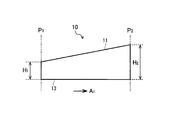
- FIG. 2A is curved arbitrary position in the first direction A 1 shown in FIG. 1 (hereinafter, "first molding position P 1") and, than the first molding position P 1 in the first direction A 1
- second molding position P 2 It is a schematic side view of the press-formed product 10 within the range of the position on the part 11c side
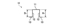
- FIG. 2B is a schematic cross-sectional view of the press-formed product 10 at the first molding position P1 in FIG. 2A.
- FIG. 2C is a schematic cross-sectional view of the press-formed product 10 at the second molding position P2 in FIG. 2A. Sectional view here illustrates the cross-section perpendicular to the first direction A 1.
- the press-molded product 10 the product height from the flange portion 13 of the first molding position P 1 is the height of the top plate portion 11 (hereinafter, "first product height is H 1 ”) is the product height from the second forming position P 2 flange portion 13 at a height of up to the top plate portion 11 (hereinafter,” second product height H 2 ") lower than ing.
- first product height H 1
- second product height H 2 second product height
- the vertical wall portion 12 of the first molding position P 1 is a line length of a cross-section perpendicular to the direction A 1 (top plate portion 11 side of the R blind flange
- the length of the straight line between the end of the portion 13 and the stop R) is a vertical length which is a first vertical wall line length D 1 and a line length of a cross section perpendicular to the first direction A 1 at the second molding position P 2 .
- the wall line length (the length of the straight line between the stop at the top plate portion 11 side and the stop at the flange portion 13 side) is referred to as a second vertical wall line length D2.
- R stop in the present embodiment is a boundary between a curved region and a plane region.
- the product height of the press-molded product 10 is continuously increased from the first forming position P 1 toward the second molding position P 2, describes an example in which the product height changes
- the product height of the press-formed product 10 is not limited to an example in which the height is continuously increased. Changing areas of the product height, may be contained in a portion between the first molding position P 1 of the second forming position P 2.
- the product height may be the product height has become continuously lower.
- the period from the first molding position P 1 of the press-molded product 10 to the second forming position P 2 part a product height increases continuously lower becomes part may be mixed.
- the press-molded product 10, the product height may include portions which do not change during the period from the first forming position P 1 to a second forming position P 2.
- FIGS. 3 and 4 are schematic side views for illustrating a modified example of the press-formed product 10.
- the first molding position P 1 over the second forming position P 2 the product height H of the press-molded product 10 is changed stepwise.
- the first molding position P 1 over the second forming position P 2 when viewed from a direction perpendicular to the wall surface of the vertical wall portion 12, the top plate portion 11 and the flange portion 13 is curved
- the product height H is changing continuously.
- a press-formed product 10 as shown in FIGS. 3 and 4 is also included in the present invention.
- the press-formed product according to the present embodiment has a ratio (H max / H min) between the maximum product height H max of the press-formed product 10 and the minimum product height H min of the press-formed product 10 in the first stretched portion 11a. ) Preferably satisfy the following relationship (Equation 1).
- the above expression 1 is satisfied not only in the above-described first extending portion 11a but also in the second extending portion 11b and the curved portion 11c. That is, the ratio (H max) between the maximum product height H max of the press-formed product 10 and the minimum product height H min of the press-formed product 10 from the first stretched portion 11a to the curved portion 11c and the second stretched portion 11b. / H min ) more preferably satisfies the following relationship (Equation 1).
- the maximum product height H max of the press-formed product 10 means a product height at a position where the product height of the press-formed product 10 is highest.
- the minimum product height H min of the press-formed product 10 means a product height at a position where the product height of the press-formed product 10 is the lowest.
- the press-formed product 10 shown in FIGS. 1 and 2 includes a first step of processing a blank into an intermediate product 20 shown in FIGS. 7A to 7C and 9 described later, and the intermediate product 20 shown in FIGS. 1 and 2A. It is manufactured through a second step of processing into a press-formed product 10 shown in FIG. 2C.
- the intermediate product 20 is manufactured by drawing a blank in a first step
- the press-formed product 10 is manufactured by bending the intermediate product 20 in a second step.
- FIGS. 7A to 7C and FIG. I a portion corresponding to the top plate portion 11 of the finished product (press-formed product 10) in the intermediate product 20 shown in FIGS. 7A to 7C and FIG. I do.
- a portion corresponding to the vertical wall portion 12 of the finished product (press-formed product 10) is referred to as an intermediate vertical wall portion 22, and a flange portion 13 of the finished product (press-formed product 10) in the intermediate product 20 is provided.
- the corresponding portion is called an intermediate flange portion 23.
- the vertical wall line length is a line length in a cross section perpendicular to the first direction A 1 (middle top plate portion
- the length of the straight line between the R-stop on the 21 side and the R-stop on the intermediate flange portion 23) is the first intermediate vertical wall line length d 1 , as shown in FIG. 7A and FIG. 7C.
- the intermediate vertical wall portion 22 in the two, between the first vertical wall line length is a line length in a cross section perpendicular to the direction a 1 (R stubbornly intermediate top panel section 21 side and the intermediate flange portion 23 side of the R blind Is the second intermediate vertical wall line length d 2
- the molding height at the first molding position P 1 from the intermediate flange portion 23 to the intermediate top plate portion 21 is the first molding length.
- height h 1 the height from the second forming position P 2 intermediate flange section 23 in to the intermediate top panel section 21 formed The height referred to as the second forming height h 2.
- FIG. 5A is a side view illustrating an example of the intermediate product 120 according to the related art.
- FIG. 5B is a schematic sectional view of the intermediate product 120 at the first molding position P1 in FIG. 5A.
- FIG. 5C is a schematic sectional view of the intermediate product 120 at the second molding position P2 in FIG. 5A. Sectional view here illustrates the cross-section perpendicular to the first direction A 1.
- the angle a middle top plate portion 121 and the intermediate vertical wall portion 122 is It becomes vertical, and like the first forming height h 1 and the second forming height h 2 of the intermediate product 120 is the same, the processing in the first step are being subjected.
- the first forming height h 1 is the first product has become the height H 1 and the same press-formed product 10 is finished as shown in FIG. 2B, the first intermediate vertical wall of the intermediate product 120 line length d 1 is also the same as those vertical wall line length D 1 first of the press-molded product 10 shown in Figure 2B. Therefore, the intermediate product 120 in FIG.
- 5A ⁇ 5C are shaped in a first molding position P 1 has become equivalent to the shape of the press-molded product 10 of the first molding position P 1.
- the intermediate product 120 in FIG. 5A ⁇ 5C are provided second forming height h 2 different from the second product height H 2 of the press-molded product 10 shown in FIG. 2C, similarly, a second also the intermediate vertical wall line length d 2 is different from the second vertical wall line length D 2.
- the second intermediate vertical wall line shown in FIG. the length d 2 it is necessary to process to match the second vertical wall line length D 2 of the press-molded product 10 shown in FIG. 2C. That is, the intermediate flange portion 123 is bent back as shown in FIG. 6 by the processing in the second step, and the flange portion 13 as the press-formed product 10 needs to be newly formed on the plate surface of the intermediate flange portion 123. .
- the cross-sectional shape of the press-formed product 10 after bending and stretching is indicated by a broken line.
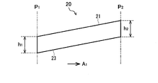
- FIG. 7A is a side view showing the intermediate product 20 manufactured by the processing in the first step, according to an embodiment of the present invention.
- FIG. 7B is a schematic sectional view of the intermediate product 20 at the first molding position P1 in FIG. 7A.
- FIG. 7C is a schematic sectional view of the intermediate product 20 at the second molding position P2 in FIG. 7A. Sectional view here illustrates the cross-section perpendicular to the first direction A 1.
- the first forming height h 1 and the second forming height h 2 are the same.
- the cross-sectional shape at the second molding position P2 shown in FIG. 7C is different from the cross-sectional shape of the conventional intermediate product 120 shown in FIG. 5C. More specifically, in the conventional intermediate product 120 shown in FIG. 5C, the angle of the second intermediate top panel section 21 in the molding position P 2 of the intermediate vertical wall portion 22 is perpendicular, the second intermediate Tatekabesen the length d 2 is smaller than the second vertical wall line length D 2 of the press-molded product 10 is finished.
- the second intermediate vertical wall line length d 2 is the same as those vertical wall line length D 2 second of the press-molded product 10.
- Intermediate vertical wall line length d 2 of the intermediate product 20 in the second shown in Fig. 7C is a second identical vertical wall line length D 2 of the press-molded product 10, the second intermediate vertical wall line length d 2 When the second vertical wall line length D 2 may not be necessarily the same. Similarly, the first intermediate vertical wall line length d 1 first vertical wall line length D 1 also may not necessarily identical.
- the ratio (d 1 / D 1 ) of the first intermediate vertical wall line length d 1 to the first vertical wall line length D 1 is 0.80 to 1. 20 should be satisfied. That is, 0.80 ⁇ (d 1 / D 1 ) ⁇ 1.20 is satisfied.
- d 1 / D 1 is less than 0.80, the boundary between the intermediate flange portion 23 and the intermediate vertical wall portion 22 is located at the vertical wall portion 12 of the press-formed product 10 which is a finished product. For this reason, a pattern residue tends to occur on the vertical wall portion 12 of the press-formed product 10.
- d 1 / D 1 It is more preferred lower limit of d 1 / D 1 is 0.90, that is, d 1 / D 1 ⁇ 0.90.
- d 1 / D 1 is 0.90 or more, the remaining pattern of the vertical wall portion 12 of the press-formed product 10 can be more stably suppressed.
- the upper limit of d 1 / D 1 is more preferably 1.10.
- d 1 / D 1 is equal to or less than 1.10, the remaining pattern of the flange portion 13 can be more stably suppressed.
- the ratio (d 2 / D 2 ) of the second intermediate vertical wall line length d 2 to the second vertical wall line length D 2 is 0.80 to 0.80. It suffices to satisfy 1.20. That is, 0.80 ⁇ (d 2 / D 2 ) ⁇ 1.20 is satisfied.
- d 2 / D 2 is less than 0.80, the boundary between the intermediate flange portion 23 and the intermediate vertical wall portion 22 is located on the vertical wall portion 12 of the press-formed product 10 which is a finished product. For this reason, a pattern residue tends to occur on the vertical wall portion 12 of the press-formed product 10.
- d 2 / D 2 ⁇ 0.90 that is, the lower limit of d 2 / D 2 is 0.90.
- d 2 / D 2 ⁇ 1.10 that is, the upper limit of d 2 / D 2 is 1.10.
- the ratio (h 2 / h 1 ) between the second forming height h 2 and the first forming height h 1 of the intermediate product 20 is 0.80 to 1 .20, that is, 0.80 ⁇ (h 2 / h 1 ) ⁇ 1.20.
- h 2 / h 1 is less than 0.80, when bending the intermediate product 20 in the second step, distortion occurs between the first forming position P 1 and the second forming position P 2 , The top plate 11 is partially stressed. For this reason, wrinkles are easily generated in the top plate portion 11 of the press-formed product 10.
- the lower limit of h 2 / h 1 0.90 i.e. more preferably h 2 / h 1 ⁇ 0.90
- h 2 / h 1 Is more preferably 1.10, that is, h 2 / h 1 ⁇ 1.10.
- the intermediate product 20 that satisfies the above conditions is processed so that the press-formed product 10 is formed in the second process.
- the generation of wrinkles and remaining patterns can be prevented. For this reason, the appearance quality of the press-formed product 10 can be improved.
- the material of the blank is not particularly limited, but, for example, a steel plate is used.
- wrinkles of the top plate portion 11 and remaining patterns of the vertical wall portion 12 can be suppressed even for a high-tensile material having high molding difficulty. Therefore, when a steel plate having a tensile strength of 590 MPa or more is used as the blank material, the effect of improving the appearance quality is more remarkably exhibited.
- the angle formed by the intermediate top plate portion 21 and the intermediate vertical wall portion 22 at the time of processing in the first step of the present embodiment is determined by the vertical wall line length and the product height of the press-formed product 10 and the top plate portion 11. It is appropriately set according to the angle between the vertical wall portion 12 and the like.
- any of the position P n, the position of the intermediate product 20 between the first molding position P 1 and the second molding position P 2 of the present embodiment in the press molded article 10 shown in FIGS. 2A ⁇ 2C the intermediate vertical wall line length d n is the second intermediate vertical wall line length d 2 following an intermediate product 20 in the second molding position P 2.
- an arbitrary position P n, in the second and the molding position P 2, the width of the intermediate top panel section 21 (line length of the intermediate top panel section 21 in the first cross-section perpendicular to the direction A 1) is identical If it is, the angle between the intermediate top panel section 21 and the intermediate vertical wall portion 22 at an arbitrary position P n (an interior angle) of the intermediate top panel section 21 and the intermediate vertical wall portion in a second molding position P 2 22 (inner angle).
- FIG. 9 is a schematic perspective view showing a part of the intermediate product 20 according to the present embodiment.
- Perspective view of FIG. 9, not the entire intermediate product 20, shows a part of the intermediate product 20 in the range of, as shown in FIG. 7A, the first molding position P 1 to a second forming position P 2 is there.
- the first intermediate vertical wall line length d 1 is a first vertical wall line length D 1 is the same
- the second intermediate vertical wall line length d 2 and the second vertical wall line length D 2 are the same has been described an example in which the first forming height h 1 and the second forming height h 2 performs the processing in the first step to be the same.
- the present invention is not limited to this embodiment.
- the manufacturing equipment 30 for the press-formed product 10 includes a first mold 40 for processing the blank 60 into the intermediate product 20 and a second mold 40 for processing the intermediate product 20 into the press-formed product 10. And a mold 50.
- the first die 40 is a drawing die configured to perform drawing
- the second die 50 is a bending die configured to perform bending. It is a mold.
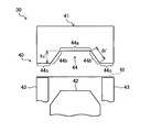
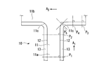
- FIG. 10 is a schematic cross-sectional view of the first mold 40 in a second molding position P 2 of the present embodiment.
- the first die 40 of the present embodiment surrounds the periphery of the punch 42 and the processing die 41 for drawing, which is disposed as an upper die, the punch 42 facing the processing die 41 which is disposed as a lower die.
- Blank holder 43 arranged as described above.
- the processing die 41 has a concave portion 44 that meshes with the top of the punch 42.
- the concave portion 44 has a surface 44a having the same shape as the shape of the intermediate top plate portion 21 and a surface 44b having the same shape as the shape of the intermediate vertical wall portion 22 connected to the surface.
- a surface 44c connected to the surface 44b is formed in a portion of the processing die 41 facing the blank holder 43. Since these surfaces 44a to 44c are formed on the processing die 41, when the first mold 40 is closed, the intermediate top plate portion 21, the intermediate vertical wall portion 22, and the intermediate flange portion of the intermediate product 20 are formed. The molding of the part 23 is performed. That is, the surfaces 44a to 44c of the processing die 41 correspond to a portion for forming the intermediate top plate portion 21, a portion for forming the intermediate vertical wall portion 22, and a portion for forming the intermediate flange portion 23, respectively.
- the portion of the first mold 40 where the intermediate top plate portion 21 is formed is the intermediate top plate forming portion 44a
- the portion where the intermediate vertical wall portion 22 is formed is the intermediate vertical wall forming portion 44b
- a portion where the intermediate flange portion 23 is formed is referred to as an intermediate flange forming portion 44c.
- the processing die 41 and the blank holder 43 are lowered or the punch is pressed while the blank 60 is held by the processing die 41 and the blank holder 43.
- the blank 60 is pushed into the concave portion 44 of the processing die 41 as shown in FIG. 11.
- the blank 60 is processed into a shape following the shape of the concave portion 44 of the processing die 41, and the intermediate product 20 is manufactured.
- Figure 12 is a schematic sectional view showing a working die 41 of the first die 40 in the first molding position P 1 of the present embodiment.
- the first intermediate vertical wall molded portion 44b in the molding position P 1 the vertical wall line is the line length in the cross section perpendicular to the first direction A 1
- the length (the length of the straight line between the R stop on the intermediate top plate forming portion 44a side and the R stop on the intermediate flange forming portion 44c) is the first intermediate vertical wall line length d 1 ′
- blind R of the first vertical wall line length is a line length in a cross section perpendicular to the direction a 1 (blind intermediate top plate forming portion 44a side R and the intermediate flange-forming portion 44c side straight length) the second intermediate vertical wall line length d 2 '
- molded height is the height from the first intermediate flange forming portion 44c at the molding position P 1 to the intermediate top
- the first intermediate vertical wall line length d 1 , the first molding height h 1 , the second intermediate vertical wall line length d 2 , and the second intermediate vertical wall length d 1 of the intermediate product 20 obtained by processing with the first mold 40.
- forming height h 2 of the first intermediate vertical wall line length d 1 of the first die 40 ', the first forming height h 1', the second intermediate vertical wall line length d 2 ', and Each of them is equal to the second molding height h 2 ′.
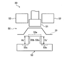
- FIG. 13 is a schematic sectional view of a second mold 50 in the second molding position P 2 of the present embodiment.
- the second mold 50 of the present embodiment includes a pad 51 arranged as an upper mold, a processing die 52 arranged to surround the periphery of the pad 51 for bending, and an anvil 53 arranged as a lower mold. It has.
- the anvil 53 has a surface 53a having the same shape as the top plate portion 11 of the press-formed product 10, a surface 53b having the same shape as the shape of the vertical wall portion 12 of the press-formed product 10 connected to the surface 53a, and a surface 53b having the same shape.
- the surfaces 53a to 53c of the anvil 53 correspond to a portion for forming the top plate portion 11, a portion for forming the vertical wall portion 12, and a portion for forming the flange portion 13, respectively.
- the portion of the second mold 50 where the top plate portion 11 is formed is the top plate forming portion 53a
- the portion where the vertical wall portion 12 is formed is the vertical wall forming portion 53b
- the flange portion 13 is The part to be formed is referred to as a flange forming part 53c.
- the intermediate top plate portion 21 is positioned between the top plate forming portion 53a of the anvil 53 and the pad 51.
- the processing die 52 is lowered as shown in FIG. Thereby, the intermediate product 20 is processed into a shape following the top plate forming portion 53a, the vertical wall forming portion 53b, and the flange forming portion 53c of the anvil 53, and the press-formed product 10 is manufactured.
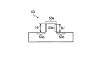
- Figure 15 is a schematic diagram showing a second anvil 53 of the die 50 in the first molding position P 1 of the present embodiment.
- the second die 50 the first vertical wall molded portion 53b in the molding position P 1 of the first cross-section perpendicular to the direction A 1
- the first vertical wall line length D 1 ′ and the second vertical wall line length (the length of the straight line between the R-stop on the top plate forming portion 53 a side and the R-stop on the flange forming portion 53 c), which is the line length, are used.
- the first vertical wall line length is a line length in a cross section perpendicular to the direction a 1 (R stoppage of the top mold portion 53a side of the flange forming portion 53c side blind vertical wall line length D 2 of the length of the straight line) a second between '
- the product height is the height from the flange forming portion 53c to the top plate forming portion 53a in the first molding position P 1 first product height H 1 '
- the product height H 2 is determined by the first vertical wall line length D 1 ′ of the second mold 50, the first product height H 1 ′, the second vertical wall line length D 2 ′, and the second vertical wall line length D 2 ′. It is equal to the product height H 2 ′.
- an intermediate product 20 of the present embodiment the first intermediate vertical wall line length d 1 of the first vertical wall line length D 1 ratio, length d 2 and a second second intermediate vertical wall line the ratio of the vertical wall line length D 2, and the second forming height h 2 first ratio forming height h 1 of, in which each satisfy 0.80 to 1.20.
- the ratio of the first intermediate vertical wall line length d 1 ′ to the first vertical wall line length D 1 ′, the second intermediate vertical wall line length d 1 The ratio of 2 ′ to the second vertical wall line length D 2 ′ and the ratio of the second forming height h 2 ′ to the first forming height h 1 ′ satisfy the same conditions as the intermediate product 20.
- the occurrence of wrinkles and remaining patterns in the press-formed product 10 can be suppressed.
- the first mold 40 and the second mold 50 have the first intermediate vertical wall line length d 1 ′ and the first vertical wall line length. It is configured such that the ratio of D 1 ′ (d 1 ′ / D 1 ′) is 0.80 to 1.20. That is, 0.80 ⁇ (d 1 ′ / D 1 ′) ⁇ 1.20 is satisfied.
- d 1 ′ / D 1 ′ is less than 0.80, the pattern remains easily formed on the vertical wall portion 12 of the press-formed product 10.
- d 1 ′ / D 1 ′ is more than 1.20, pattern residue is likely to be generated on the flange portion 13 of the press-formed product 10.
- the lower limit of d 1 ′ / D 1 ′ is more preferably 0.90.
- the upper limit of d 1 ′ / D 1 ′ is more preferably 1.10.
- the first mold 40 and the second mold 50 use the second intermediate vertical wall line length d 2 ′ and the second vertical wall line length.
- the ratio of D 2 ′ (d 2 ′ / D 2 ′) is configured to be 0.80 to 1.20. That is, 0.80 ⁇ (d 2 ′ / D 2 ′) ⁇ 1.20 is satisfied.
- d 2 ′ / D 2 ′ is less than 0.80, a pattern residue is likely to be generated on the vertical wall portion 12 of the press-formed product 10.
- d 2 ′ / D 2 ′ is more than 1.20, pattern residue is likely to occur on the flange portion 13 of the press-formed product 10.
- the lower limit of d 2 ′ / D 2 ′ is more preferably 0.90.
- the upper limit of d 2 ′ / D 2 ′ is more preferably 1.10.
- the first mold 40 has a ratio (h 2 ′ / h 2 ′) between the second molding height h 2 ′ and the first molding height h 1 ′.
- h 1 ′) is set to be 0.80 to 1.20. That is, 0.80 ⁇ (h 2 ′ / h 1 ′) ⁇ 1.20 is satisfied.
- h 2 ′ / h 1 ′ is less than 0.80, wrinkles are likely to be generated on the top plate 11 of the press-formed product 10.
- h 2 ′ / h 1 ′ exceeds 1.20, wrinkles are likely to occur on the top plate 11 of the press-formed product 10.
- the lower limit of h 2 ′ / h 1 ′ is more preferably 0.90.
- the upper limit of h 2 ′ / h 1 ′ is more preferably 1.10.
- the press-formed product 10 may have a left-right asymmetric shape.
- the vertical wall line length of the pair of vertical wall portions 12 in a cross section perpendicular to the first direction A 1 as described above may be different, with one vertical wall portion 12 and the top plate portion 11
- the angle formed and the angle formed by the other vertical wall portion 12 and the top plate portion 11 may be different from each other. Even in this case, if each of the vertical wall portions 12 satisfies the above-described ratio between the intermediate vertical wall line length and the vertical wall line length, the appearance quality of the press-formed product 10 can be improved.
- the method of forming the press-formed product 10 in the first stretched portion 11a has been described.
- the press-formed product having a shape in which the product height changes toward the curved portion 11c also in the second stretched portion 11b. If it is 10, the same molding method can be applied.
- FIG. 16 is a schematic plan view of the press-formed product 10 viewed from a direction perpendicular to the plate surface of the top plate portion.
- a first molding position P 1 and the second molding position P 2 is positioned in the first extending portion 11a.
- FIG. 16 is a schematic plan view of the press-formed product 10 viewed from a direction perpendicular to the plate surface of the top plate portion.
- a first molding position P 1 and the second molding position P 2 is positioned in the first extending portion 11a.
- FIG. 16 is a schematic plan view of the press-formed product 10 viewed from a direction perpendicular to the plate surface of the top plate portion.
- a first molding position P 1 and the second molding position P 2 is positioned in the first extending portion 11a.
- the intermediate vertical wall line length d 4 and the fourth vertical wall line length D 4 are such that d 3 / D 3 is 0.80 to 1.20, d 4 / D 4 is 0.80 to 1.20, and h 4 / H 3 may satisfy the relationship of 0.80 to 1.20.
- the fifth forming height h 5 of the fifth intermediate Tatekabesen the vertical wall line length D 5 of length d 5 and the fifth, second forming height h 2 may be replaced each second in the intermediate vertical wall line length d 2 and a second vertical wall line length D 2 .
- the fifth forming height h 5 of the intermediate vertical wall line length d 5 and the fifth vertical wall line length D 5 of the fifth, fourth forming height h 4, a fourth intermediate vertical wall line length d 4 and the fourth vertical wall line length D 4 may be used.
- the shape of the press-formed product 10 is not limited to the shape described in the above embodiment.
- the press-formed product 10 may have, for example, an L-shaped shape in which one end of a first extension 11a and one end of a second extension 11b are connected via a curved portion 11c.
- the press-formed product 10 further includes a third extending portion (not shown) which is a portion extending in a third direction (not shown) such as a Y-shape, for example, and one end of the first extending portion 11a, One end of the second extended portion 11b and one end of the third extended portion may be connected to each other via the curved portion 11c.
- the press-formed product 10 is, for example, an automobile part including at least one of a T-shape, an L-shape, and a Y-shape in plan view.
- the press-formed product is, for example, a center pillar outer, a front pillar lower or a side panel outer.
- the first direction described above may be replaced with a third direction, and in this third direction as well, the press-formed product 10 in which the third extending portion changes in product height toward the curved portion 11c. Then, in the third direction, the same molding positions as the above-described first molding position P 1 to fourth molding position P 4 are set, and the method of manufacturing a press-molded product according to the above embodiment is set. Can be applied.
- FIG. 17 is a schematic perspective view showing another example of the press-formed product 10 according to the embodiment.
- Press-molded product 10 in FIG. 17, the overall configuration is similar to the press-molded product 10 shown in FIG. 1, the first product height at the first molding position P 1 H 1 and second molding position the difference between the second product height H 2 at P 2 is smaller than the example of FIG.
- the drawing is performed in the first step, but the processing method in the first step is not limited to the drawing.
- the ratio (d 1 / D 1 ) of the first intermediate vertical wall line length d 1 to the first vertical wall line length D 1 satisfies 0.80 to 1.20
- 2, the ratio (d 2 / D 2 ) of the intermediate vertical wall line length d 2 to the second vertical wall line length D 2 satisfies 0.80 to 1.20
- the second molding height h 2 and the first Any processing method may be used as long as an intermediate product 20 that satisfies the ratio (h 2 / h 1 ) of the molding height h 1 (h 2 / h 1 ) of 0.80 to 1.20 is obtained.
- the processing method in the second step is not limited to bending.
- the first die 40 is a drawing die configured to perform drawing, but the first die 40 is a drawing die. Not limited.
- the first mold 40 has a ratio (d 1 ′ / D 1 ′) of the first intermediate vertical wall line length d 1 ′ to the first vertical wall line length D 1 ′ of 0.80 to 1.20.
- the ratio (d 2 ′ / D 2 ′) of the second intermediate vertical wall line length d 2 to the second vertical wall line length D 2 satisfies 0.80 to 1.20, and the second forming height It suffices if the ratio (h 2 ′ / h 1 ′) between h 2 ′ and the first molding height h 1 ′ satisfies 0.80 to 1.20.
- the second mold 50 is not limited to a bending mold configured to perform a bending process.
- a molding simulation (software used: J-STAMP) of a press-formed product having a shape as shown in FIG. 1 was performed to evaluate the appearance of the press-formed product.
- the forming simulation was performed as a first step to obtain an intermediate product and a press-formed product (the first product height was 80 mm and the second product height was 96 mm) satisfying the conditions shown in Table 1 below.
- the processing and the bending as the second step were set as manufacturing conditions.
- the blank is a steel plate having a tensile strength of 980 MPa.
- the appearance quality is evaluated by observing the top plate, vertical wall, and flange of the press-formed product of the analysis model with shading display, and determining the occurrence of wrinkles and remaining patterns by sensory evaluation. I was
- the present invention can be used for manufacturing press-formed products of automobiles.
Landscapes
- Engineering & Computer Science (AREA)
- Mechanical Engineering (AREA)
- Shaping Metal By Deep-Drawing, Or The Like (AREA)
- Bending Of Plates, Rods, And Pipes (AREA)
Abstract
La présente invention concerne un procédé de fabrication d'un produit formé à la presse, un produit formé à la presse (10) incluant une partie plaque supérieure (11), une partie paroi longitudinale (12) et une partie bride (13), et la hauteur de la partie bride (13) à la partie plaque supérieure (11) change d'une première hauteur de produit H1 à une seconde hauteur de produit H2 entre une première position de formation P1 et une seconde position de formation P2, et, dans une première étape, un produit intermédiaire étant fabriqué par l'usinage d'une ébauche, le produit intermédiaire satisfaisant les relations suivantes : une première longueur linéaire de paroi longitudinale intermédiaire d1/une première longueur linéaire de paroi longitudinale D1 : 0,80 à 1,20, une seconde longueur linéaire de paroi longitudinale intermédiaire d2/une seconde longueur linéaire de paroi longitudinale D2 : 0,80 à 1,20, et une seconde hauteur formée h2/une première hauteur formée h1 : 0,80 à 1,20, et dans une seconde étape, le produit formé à la presse (10) est fabriqué par l'usinage du produit intermédiaire.
Priority Applications (2)
| Application Number | Priority Date | Filing Date | Title |
|---|---|---|---|
| JP2019561198A JP6680416B1 (ja) | 2018-06-29 | 2019-06-28 | プレス成形品の製造方法および製造設備 |
| MYPI2020006690A MY205030A (en) | 2018-06-29 | 2019-06-28 | Manufacturing method of press-formed article, and manufacturing facility for press-formed article |
Applications Claiming Priority (2)
| Application Number | Priority Date | Filing Date | Title |
|---|---|---|---|
| JP2018-124149 | 2018-06-29 | ||
| JP2018124149 | 2018-06-29 |
Publications (1)
| Publication Number | Publication Date |
|---|---|
| WO2020004610A1 true WO2020004610A1 (fr) | 2020-01-02 |
Family
ID=68984934
Family Applications (1)
| Application Number | Title | Priority Date | Filing Date |
|---|---|---|---|
| PCT/JP2019/025773 Ceased WO2020004610A1 (fr) | 2018-06-29 | 2019-06-28 | Procédé de fabrication d'un produit formé à la presse et installation de fabrication |
Country Status (3)
| Country | Link |
|---|---|
| JP (1) | JP6680416B1 (fr) |
| MY (1) | MY205030A (fr) |
| WO (1) | WO2020004610A1 (fr) |
Cited By (1)
| Publication number | Priority date | Publication date | Assignee | Title |
|---|---|---|---|---|
| JP2021164954A (ja) * | 2020-04-08 | 2021-10-14 | Jfeスチール株式会社 | プレス部品の製造方法、曲げ戻し用の金型、プレス部品の成形方法及び高強度鋼板 |
Citations (3)
| Publication number | Priority date | Publication date | Assignee | Title |
|---|---|---|---|---|
| WO2011145679A1 (fr) * | 2010-05-19 | 2011-11-24 | 新日本製鐵株式会社 | Procédé pour formage à la presse d'éléments en forme de l |
| WO2012070623A1 (fr) * | 2010-11-24 | 2012-05-31 | 新日本製鐵株式会社 | Procédé pour fabriquer un produit en forme de l |
| WO2014050973A1 (fr) * | 2012-09-27 | 2014-04-03 | 新日鐵住金株式会社 | Procédé de production pour renforcement de pilier central |
-
2019
- 2019-06-28 WO PCT/JP2019/025773 patent/WO2020004610A1/fr not_active Ceased
- 2019-06-28 JP JP2019561198A patent/JP6680416B1/ja active Active
- 2019-06-28 MY MYPI2020006690A patent/MY205030A/en unknown
Patent Citations (3)
| Publication number | Priority date | Publication date | Assignee | Title |
|---|---|---|---|---|
| WO2011145679A1 (fr) * | 2010-05-19 | 2011-11-24 | 新日本製鐵株式会社 | Procédé pour formage à la presse d'éléments en forme de l |
| WO2012070623A1 (fr) * | 2010-11-24 | 2012-05-31 | 新日本製鐵株式会社 | Procédé pour fabriquer un produit en forme de l |
| WO2014050973A1 (fr) * | 2012-09-27 | 2014-04-03 | 新日鐵住金株式会社 | Procédé de production pour renforcement de pilier central |
Cited By (2)
| Publication number | Priority date | Publication date | Assignee | Title |
|---|---|---|---|---|
| JP2021164954A (ja) * | 2020-04-08 | 2021-10-14 | Jfeスチール株式会社 | プレス部品の製造方法、曲げ戻し用の金型、プレス部品の成形方法及び高強度鋼板 |
| JP7226382B2 (ja) | 2020-04-08 | 2023-02-21 | Jfeスチール株式会社 | プレス部品の製造方法、曲げ戻し用の金型、及びプレス部品の成形方法 |
Also Published As
| Publication number | Publication date |
|---|---|
| JPWO2020004610A1 (ja) | 2020-07-02 |
| JP6680416B1 (ja) | 2020-04-15 |
| MY205030A (en) | 2024-09-28 |
Similar Documents
| Publication | Publication Date | Title |
|---|---|---|
| EP2998043B1 (fr) | Méthode de fabrication d'un composant travaillé | |
| JP5959702B1 (ja) | プレス成形品の製造方法及びプレス成形型 | |
| JP6590071B2 (ja) | プレス成形品の製造方法 | |
| JP6330930B1 (ja) | プレス成形方法 | |
| CN115397577B (zh) | 冲压成形方法以及冲压成形件 | |
| WO2015155974A1 (fr) | Procédé de fabrication d'article moulé à la presse et bras inférieur de véhicule | |
| CN108698104B (zh) | 冲压成型品的制造方法 | |
| JP2018020349A (ja) | 金型の設計方法およびプレス成形品の製造方法 | |
| EP3666409B1 (fr) | Procédé de fabrication d'un article moulé à la presse | |
| JP6672933B2 (ja) | 自動車用構造部材、およびその製造方法、金型 | |
| JP6112226B2 (ja) | プレス成形方法、及びプレス成形部品の製造方法 | |
| EP3895824B1 (fr) | Procédé de formage à la presse | |
| WO2020004610A1 (fr) | Procédé de fabrication d'un produit formé à la presse et installation de fabrication | |
| WO2017149955A1 (fr) | Procédé de fabrication de produit moulé par compression | |
| JP5079604B2 (ja) | 金属製断面ハット型形状部材のプレス成形用金型およびプレス成形方法 | |
| KR102330195B1 (ko) | 성형체, 구조 부재, 및 성형체의 제조 방법 | |
| JP6176430B1 (ja) | プレス成形品の製造方法 | |
| JP2019209352A (ja) | プレス成形方法及びプレス成形装置 | |
| JP7704721B2 (ja) | プレス成形品の製造方法 | |
| JP2018020351A (ja) | プレス成形品の製造方法 | |
| JP6176429B1 (ja) | プレス成形品の製造方法 | |
| JP7679921B1 (ja) | プレス成形品の製造方法 | |
| CN118543746B (zh) | 一种汽车底盘零件的冷冲压制造工艺方法 | |
| CN112676416B (zh) | 车身骨架构件的制造方法 | |
| WO2025126590A1 (fr) | Procédé de fabrication d'un article formé à la presse |
Legal Events
| Date | Code | Title | Description |
|---|---|---|---|
| ENP | Entry into the national phase |
Ref document number: 2019561198 Country of ref document: JP Kind code of ref document: A |
|
| 121 | Ep: the epo has been informed by wipo that ep was designated in this application |
Ref document number: 19826288 Country of ref document: EP Kind code of ref document: A1 |
|
| NENP | Non-entry into the national phase |
Ref country code: DE |
|
| 122 | Ep: pct application non-entry in european phase |
Ref document number: 19826288 Country of ref document: EP Kind code of ref document: A1 |