WO2020004620A1 - 累進屈折力レンズの設計方法、製造方法、設計システム及び累進屈折力レンズ - Google Patents
累進屈折力レンズの設計方法、製造方法、設計システム及び累進屈折力レンズ Download PDFInfo
- Publication number
- WO2020004620A1 WO2020004620A1 PCT/JP2019/025807 JP2019025807W WO2020004620A1 WO 2020004620 A1 WO2020004620 A1 WO 2020004620A1 JP 2019025807 W JP2019025807 W JP 2019025807W WO 2020004620 A1 WO2020004620 A1 WO 2020004620A1
- Authority
- WO
- WIPO (PCT)
- Prior art keywords
- lens
- progressive
- difference
- eye
- sight
- Prior art date
- Legal status (The legal status is an assumption and is not a legal conclusion. Google has not performed a legal analysis and makes no representation as to the accuracy of the status listed.)
- Ceased
Links
Images


Classifications
-
- G—PHYSICS
- G02—OPTICS
- G02C—SPECTACLES; SUNGLASSES OR GOGGLES INSOFAR AS THEY HAVE THE SAME FEATURES AS SPECTACLES; CONTACT LENSES
- G02C7/00—Optical parts
- G02C7/02—Lenses; Lens systems ; Methods of designing lenses
- G02C7/024—Methods of designing ophthalmic lenses
- G02C7/025—Methods of designing ophthalmic lenses considering parameters of the viewed object
-
- G—PHYSICS
- G02—OPTICS
- G02C—SPECTACLES; SUNGLASSES OR GOGGLES INSOFAR AS THEY HAVE THE SAME FEATURES AS SPECTACLES; CONTACT LENSES
- G02C7/00—Optical parts
- G02C7/02—Lenses; Lens systems ; Methods of designing lenses
- G02C7/024—Methods of designing ophthalmic lenses
- G02C7/027—Methods of designing ophthalmic lenses considering wearer's parameters
-
- G—PHYSICS
- G02—OPTICS
- G02C—SPECTACLES; SUNGLASSES OR GOGGLES INSOFAR AS THEY HAVE THE SAME FEATURES AS SPECTACLES; CONTACT LENSES
- G02C7/00—Optical parts
- G02C7/02—Lenses; Lens systems ; Methods of designing lenses
- G02C7/06—Lenses; Lens systems ; Methods of designing lenses bifocal; multifocal ; progressive
- G02C7/061—Spectacle lenses with progressively varying focal power
- G02C7/063—Shape of the progressive surface
-
- G—PHYSICS
- G02—OPTICS
- G02C—SPECTACLES; SUNGLASSES OR GOGGLES INSOFAR AS THEY HAVE THE SAME FEATURES AS SPECTACLES; CONTACT LENSES
- G02C7/00—Optical parts
- G02C7/02—Lenses; Lens systems ; Methods of designing lenses
- G02C7/06—Lenses; Lens systems ; Methods of designing lenses bifocal; multifocal ; progressive
- G02C7/061—Spectacle lenses with progressively varying focal power
- G02C7/068—Special properties achieved by the combination of the front and back surfaces
-
- G—PHYSICS
- G02—OPTICS
- G02C—SPECTACLES; SUNGLASSES OR GOGGLES INSOFAR AS THEY HAVE THE SAME FEATURES AS SPECTACLES; CONTACT LENSES
- G02C7/00—Optical parts
- G02C7/14—Mirrors; Prisms
Definitions
- the present invention relates to a progressive power lens design method, a manufacturing method, a design system, and a progressive power lens.
- the contents of Japanese Patent Application No. 2018-123739, which is the basis of the priority, can be referred to in this specification.
- Such a spectacle lens is also called a progressive-power lens.
- a so-called progressive multifocal lens having a distance portion and a near portion is exemplified.
- Another example is an aspheric single-focal lens whose power varies as the distance from one area for viewing a predetermined distance increases.
- a curve called a main gazing line is set as a reference line when the power continuously changes from the distance portion to the near portion.
- the main gazing line refers to eyeglasses when a wearer wears a spectacle lens and shifts his / her line of sight from a vertical heaven direction (above), which is the vertical direction, to the ground direction (below), or vice versa. It refers to a line formed by gathering the parts where the line of sight passes most frequently in the lens.
- This main line of sight is a basic part when designing a spectacle lens.
- the lens shape of the progressive-power lens is designed so that the power that changes from the distance portion to the near portion along the main line of sight becomes the power change specified in the prescription information.
- Patent Document 1 discloses a technique relating to a progressive-power lens having a surface on the object side (outer surface, convex surface) and a surface on the eyeball side (inner surface, concave surface). Specifically, the refractive power in the vertical and horizontal directions at the distance reference point, which is the distance power measurement position on the outer surface, and the vertical and horizontal refractive power at the near reference point, which is the near power measurement position on the outer surface, are predetermined. A technique for controlling so as to satisfy the relationship is disclosed. It is disclosed that this control reduces the difference in perspective magnification which is peculiar to the progressive-power lens, and reduces distortion perceived by the wearer.
- Patent Document 2 discloses that an action of an out-prism that can occur in a portion where a main gaze line in which the wearer's convergence is taken into consideration passes can occur. It is disclosed that the shape of the in-prism that at least partially offsets the action of the out-prism is provided in the portion from the distance portion to the near portion on the main line of sight of the progressive-power lens. It is disclosed that the state in which a larger convergence is exerted on the action of the out prism on the main gaze can be reduced by the action of the in prism.
- the inventor paid attention to the following problems unique to the progressive-power lens.
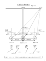
- FIG. 1 shows a conventional progressive-power lens 10R for a right eye and a lens 10L for a left eye, which are conventional progressive power lenses, when the direction of the earth in the top and bottom (vertical upward) is viewed from the direction of the ceiling (vertical upward).
- 1 is a schematic diagram showing the position of an apparent target object plane 20 for a wearer, as seen through a spectacle lens 10.
- FIG. Hereinafter, the apparent target object plane 20 is also referred to as “apparent plane 20”.
- FIG. 2 shows that in the state A when viewing the object at a point O on the median plane of the wearer a finite distance ahead of the wearer, the position of the apparent surface 20 in the depth direction seen through the progressive power lens is the actual target.
- FIG. 3 is a schematic explanatory view showing a state of being located on the near side with respect to a depth direction of an object plane 22.
- the actual target object plane 22 is also referred to as “actual plane 22”.
- the position of the apparent surface 20 in the depth direction is located on the near side with respect to the position of the actual surface 22 in the depth direction.
- the object at the point P located at the same height in the vertical direction as the point O and located on the lateral side of the point O in the horizontal direction.
- the state B at the time of visual recognition is assumed.
- the position in the depth direction of the apparent surface 20 seen through the spectacle lens 10 is located on the depth side with respect to the depth direction of the actual surface 22, as shown in FIG.
- the apparent position in the depth direction changes due to the convergence difference between the left and right eyes during binocular vision.
- the apparent position in the depth direction at the front location O and the apparent position in the depth direction at the side location P are often different. As a result, image distortion in the depth direction may occur. If this image distortion is eliminated, a comfortable wearing feeling can be obtained.
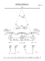
- FIG. 3 shows the right eye R when viewing an object at a short distance and a side through a right eye lens 10R and a left eye lens 10L, which are conventional progressive power lenses, when viewed from the horizontal direction.
- FIG. 7 is a diagram illustrating a state in which a vertical eye position difference occurs between a left eye L and a left eye L;
- the wearer if a difference in the direction of the line of sight occurs between the eyes in the vertical direction when the user wears the spectacle lens and gazes at one point, the wearer identifies the eyes in the state of binocular vision. Then, the eyes are forcibly shifted to different eye positions on the left and right in the vertical direction.
- the direction of the line of sight refers to the direction of the line of sight on the eyeball side, and refers to the direction in which the right eyeball or the left eyeball faces.
- the human eye has a small tolerance for the difference in the prism action in the vertical direction, and even if the eyes can be identified with each other, it is likely to cause an unpleasant wearing feeling. If the degree exceeds the tolerance of the wearer, the image will be perceived as double vision. Eliminating the vertical eye difference can suppress such perception of an image, and a comfortable wearing feeling can be obtained.
- the “element caused by the necessary prism action” includes, for example, the amount of convergence required when viewing through a lens to which an addition power is added to support accommodation power.
- the amount of convergence indicates the degree to which the left and right eyes are shifted inward when viewing an object at a short distance, and is also referred to as an inward shift amount in this specification.
- the “inward shift amount” in this specification may indicate the degree of inward shift in one eye or may indicate the degree of inward shift in both eyes.
- the present inventor states that, when the progressive-power lens is worn, a state in which the object at a point O on the median surface of the wearer at a finite distance ahead from the wearer is visually recognized (state A described later, progressive front view state A). ) And the difference V between the aforementioned progressive side viewing state B.
- both the right and left eyes will be inset. Therefore, in the progressive front view state A, the distortion in the depth direction and the eye difference in the vertical direction already include a basic element caused by the inward shifting. Then, by focusing on the difference between the front view state and the side view state, a basic element caused by the amount of inset is subtracted. In other words, whether the progressive power lens for the right eye or the progressive power lens for the left eye accepts the convergence angle and eye difference between the left and right eyes when the line of sight passes through the main gaze. As a result, the difference between the difference V and the difference W is in a state mainly reflecting elements generated by unnecessary prism action due to the progressive action. In other words, it is possible to consider factors caused by unnecessary prism action due to the progressive action.
- the difference W between the reference front view state C and the reference side view state D was noted even in a single focus lens or a state equivalent to the naked eye.
- the progressive-power lens so that the difference V approaches the difference W, the state when the progressive-power lens is worn is changed to the state when the single focus lens is worn or the state equivalent to the naked eye. I came up with a method of approaching.
- a first aspect of the present invention provides: When wearing a progressive power lens, A state A when viewing the object at a point O on the median plane of the wearer finite distance ahead of the wearer, In a plane parallel to the frontal plane and including the point O, the state B when the object at the point P located horizontally on the side of the point O at a constant height in the vertical direction relative to the point O is viewed.
- This is a progressive power lens design method that adjusts the surface shape of the progressive power lens so as to approach the difference W from the state D when the object at the point P is visually recognized.
- a second aspect of the present invention is an aspect according to the first aspect, wherein
- the difference V is an angle difference VA between the direction of the line of sight of the right eye and the direction of the line of sight of the left eye in state A, and an angle difference VB between the direction of the line of sight of the right eye and the direction of the line of sight of the left eye in state B.
- the difference W is an angle difference WC between the direction of the line of sight of the right eye and the direction of the line of sight of the left eye in state C, and an angle difference WD between the direction of the line of sight of the right eye and the direction of the line of sight of the left eye in state D.
- the difference V falls within a predetermined allowable range from the difference W.
- a third aspect of the present invention is an aspect according to the second aspect, wherein When imagining a progressive power lens for the integrated eye and the integrated eye with the center of rotation set on the median plane of the wearer and at an intermediate position between the right eye and the left eye,
- the angle difference VA is, in the state A, an angle difference VAR between the direction of the line of sight of the right eye and the direction of the line of sight of the integrated eye, and an angle difference VAL between the direction of the line of sight of the left eye and the direction of the line of sight of the integrated eye.
- the angle difference VB is the angle difference VBR between the direction of the line of sight of the right eye and the direction of the line of sight of the integrated eye in state B, and the angle difference VBL between the direction of the line of sight of the left eye and the direction of the line of sight of the integrated eye.
- Difference The angle difference WC is the angle difference WCR between the direction of the line of sight of the right eye and the direction of the line of sight of the integrated eye in state C, and the angle difference WCL between the direction of the line of sight of the left eye and the direction of the line of sight of the integrated eye.
- the angle difference WD is an angle difference WDR between the direction of the line of sight of the right eye and the direction of the line of sight of the integrated eye in state D, and the angle difference WDL between the direction of the line of sight of the left eye and the direction of the line of sight of the integrated eye. Is the difference.
- a fourth aspect of the present invention is an aspect according to the third aspect, wherein Progressive power according to at least one of a ratio of the angle difference VAR to the angle difference VAL, a ratio of the angle difference VBR to the angle difference VBL, a ratio of the angle difference WCR to the angle difference WCL, and a ratio of the angle difference WDR to the angle difference WDL.
- the correction amount for the right-eye progressive power lens and the correction amount for the left-eye progressive power lens when adjusting the surface shape of the lens are apportioned.
- a fifth aspect of the present invention is an aspect according to the third or fourth aspect, wherein As the equivalent spherical power of the progressive-power lens for the integrated eye, an average value of the equivalent spherical power of the progressive-power lens for the right eye and the equivalent spherical power of the progressive-power lens for the left eye is adopted.
- a sixth aspect of the present invention is an aspect according to any one of the second to fifth aspects, wherein The predetermined allowable range from the difference W is within 50% of the difference W.
- a designing step of performing the progressive power lens designing method according to any one of the first to sixth aspects After the design step, a processing step to obtain a progressive power lens, It is a manufacturing method of the progressive-power lens which has.
- An eighth aspect of the present invention provides: When wearing a progressive power lens, A state A when viewing the object at a point O on the median plane of the wearer finite distance ahead of the wearer, In a plane parallel to the frontal plane and including the point O, a state B when the object at the point P located horizontally on the side of the point O at a constant height in the vertical direction relative to the point O is viewed.
- the difference V of At the time of wearing the reference single focus lens corresponding to the progressive power lens or at the time of the naked eye A state C when the object at the point O is visually recognized;
- This is a progressive power lens design system including a software module for adjusting the surface shape of the progressive power lens so as to approach the difference W from the state D when the object at the point P is visually recognized.
- An intermediate portion having a progressively changing progressive action, and a progressive power lens comprising: With a prism action adjustment area that approximates the degree of image distortion due to unnecessary prism action caused by the progressive action when the reference single focus lens corresponding to the progressive power lens is worn or when the naked eye is used. It is a progressive power lens.
- a tenth aspect of the present invention is the aspect according to the ninth aspect, wherein
- the prism action adjustment area includes a lateral area deviated in the horizontal direction from the main gaze line.
- An eleventh aspect of the present invention is the aspect according to the ninth or tenth aspect, wherein At least one of the following two conditions is satisfied.
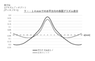
- [Condition 1] In the plot where the horizontal axis of the lens is the horizontal axis, and the vertical surface prism difference normalized by the addition is the vertical axis, the vertical surface prism at a predetermined location ⁇ on a predetermined horizontal section in the near portion is plotted. The difference between the maximum value and the minimum value of the difference is 0.2 [prism diopter / diopter] or more.
- a twelfth aspect of the present invention is an aspect according to the eleventh aspect,
- the position of the predetermined horizontal cross section is a position where 85% to 100% of the addition is achieved.
- the difference V is kept within a predetermined allowable range from the difference W by adjusting only the surface difference VB in the state B by adjusting the surface shape of the progressive-power lens.
- the equivalent spherical power of the progressive power lens is adopted as the equivalent spherical power of the reference single focus lens.
- the area for adjusting the prism action includes a lateral area horizontally deviated from the main gazing line, and more preferably includes a lateral area horizontally deviated from the main gazing line, and The area including the part is defined as a prism action adjustment area.
- the progressive-power lens may be read as a pair of progressive-power lenses including a right-eye progressive-power lens and a left-eye progressive-power lens.
- the plot of the progressive-power lens is when the reference single-focal lens corresponding to the progressive-power lens is worn. Or, it does not intersect with the plot corresponding to naked eyes.
- FIG. 1 shows a conventional progressive-power lens, a right-eye lens and a left-eye lens, and a progressive lens, as viewed from the vertical direction (vertical upward) to the vertical direction (vertical downward).
- FIG. 3 is a schematic diagram showing the position of an apparent target object plane for a wearer as seen through a power lens.
- FIG. 2 shows that, in the state A when viewing the object at the point O on the median plane of the wearer for a finite distance ahead of the wearer, the position in the depth direction of the apparent surface seen through the conventional progressive power lens is the actual position.
- FIG. 11 is a further schematic diagram illustrating a state in which the target object plane is located on the near side with respect to the depth direction.
- FIG. 3 shows a right eye and a left eye when viewing an object at a short distance and a side through a right eye lens and a left eye lens, which are conventional progressive power lenses, when viewed from the horizontal direction.
- FIG. 9 is a schematic diagram showing a state in which a vertical eye position difference is generated between and.
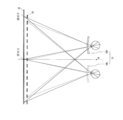
- FIG. 4A is a diagram illustrating the direction of the line of sight of the both eyes in the progressive front view state A when the design method according to one embodiment of the present invention is employed, as viewed vertically vertically from above.
- FIG. 4B is a diagram illustrating the direction of the line of sight of both eyes in the progressive side view state B when the design method according to one embodiment of the present invention is employed, as viewed vertically from above.
- FIG. 4A is a diagram illustrating the direction of the line of sight of the both eyes in the progressive front view state A when the design method according to one embodiment of the present invention is employed, as viewed vertically vertically from above.
- FIG. 4B is a diagram
- FIG. 4C is a diagram illustrating the direction of the line of sight of both eyes in the reference front view state C when the design method according to one embodiment of the present invention is employed, when looking vertically downward from vertically above.
- FIG. 4D is a diagram illustrating the direction of the line of sight of both eyes in the reference side viewing state D when the design method of one embodiment of the present invention is employed, when looking vertically downward from above vertically.
- FIG. 5 is a diagram illustrating an example of a target object plane.
- FIG. 6 is a perspective view of a right-eye lens and a left-eye lens that are progressive power lenses after adopting the design method according to one embodiment of the present invention when viewed vertically from above, and a progressive power lens.
- FIG. 6 is a perspective view of a right-eye lens and a left-eye lens that are progressive power lenses after adopting the design method according to one embodiment of the present invention when viewed vertically from above, and a progressive power lens.
- FIG. 4 is a schematic diagram showing the position of an apparent target object plane for a wearer, as seen through the camera;
- FIG. 7 shows an object at a short distance and side through a right-eye lens and a left-eye lens which are progressive power lenses after adopting the design method of one embodiment of the present invention when viewed from the horizontal direction.
- FIG. 7 is a schematic diagram showing a state in which a vertical eye position difference does not occur between the right eye and the left eye when viewing.
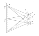
- FIG. 8A is a diagram illustrating the direction of the line of sight of the integrated eye and the binocular eyes in the progressive front view state A when the design method of one embodiment of the present invention is employed, as viewed vertically from above.
- FIG. 8B is a diagram illustrating the directions of the line of sight of the integrated eye and the two eyes in the progressive side viewing state B when the design method according to one embodiment of the present invention is employed, when looking vertically downward from vertically above.
- FIG. 8C is a diagram illustrating the direction of the line of sight of the integrated eye and the binocular eyes in the reference front view state C when the design method according to one embodiment of the present invention is employed, when looking vertically downward from vertically above.
- FIG. 8D is a diagram illustrating the direction of the line of sight of the integrated eye and both eyes in the reference side view state D when the design method according to one embodiment of the present invention is employed, when looking vertically downward from above vertically. .
- FIG. 9A and 9B are a surface average power distribution diagram (left diagram) and a surface astigmatism distribution diagram (right diagram) showing a basic design of a progressive power lens for an integrated eye employed in the design method according to one embodiment of the present invention. is there.
- FIG. 10 is a right-eye lens, a left-eye lens, and an integrated-eye lens that are progressive-power lenses after adopting the design method of one embodiment of the present invention when viewed vertically from above vertically.
- FIG. 11 is a diagram illustrating an example of a system that implements the progressive power lens design method according to one embodiment of the present invention.
- FIG. 12 is a configuration diagram showing an apparatus configuration of a design apparatus in a system that implements the progressive power lens design method according to one embodiment of the present invention.
- FIG. 13 is a diagram showing a flow of a method for designing a progressive-power lens according to one embodiment of the present invention.
- FIG. 14 is a diagram illustrating an example of the surface astigmatism distribution of the right-eye lens and the left-eye lens initially designed while inwardly adjusting the surface astigmatism distribution of the integrated ophthalmic lens.
- FIG. 15 is a diagram illustrating an example of changes in the surface average power distribution and the surface astigmatism distribution on the lens surface before and after adjustment when the left-eye lens and the right-eye lens are progressive-power lenses.
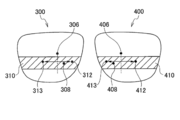
- FIG. 16 is a diagram illustrating an example of the spectacle lens 300 for the right eye in the spectacle lens pair of each embodiment.
- FIG. 17 is a diagram illustrating a method of calculating the distribution of the difference value from the lens surface prism refractive power distribution in the right-eye lens 300 and the left-eye lens 400.
- FIG. 18A shows the difference in the direction of the line of sight between the eyes in the vertical direction when the spectacle lens pair is manufactured, the lens of Example 1, and the conventional lens are worn, that is, the vertical direction.
- the horizontal axis represents the horizontal component of the line of sight
- the vertical axis represents the vertical component of the line of sight.
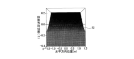
- FIG. 18B is a graph illustrating a change in an apparent position of the target object plane 22 in the depth direction, that is, a distortion in the depth direction.
- the vertical axis indicates depth direction position information [diopter], and the horizontal axis indicates the horizontal direction.
- the direction of the line of sight [tan ⁇ ] is shown.
- FIG. 19A is a diagram illustrating the direction of the line of sight in the horizontal direction, which is the horizontal axis in FIG.
- FIG. 19B is a diagram illustrating position information in the depth direction, which is the vertical axis in FIG. FIG.
- FIG. 21A shows the difference in the direction of the line of sight between the two eyes in the vertical direction when the spectacle lens pair is manufactured, the lens of Example 2, and the conventional lens are worn, that is, the vertical direction.
- the horizontal axis represents the horizontal component of the line of sight, and the vertical axis represents the vertical component of the line of sight.
- FIG. 21B is a graph illustrating a change in an apparent position of the target object plane 22 in the depth direction, that is, a distortion in the depth direction.
- the vertical axis indicates depth direction position information [diopter], and the horizontal axis indicates the horizontal direction.
- the direction of the line of sight [tan ⁇ ] is shown.
- the vertical direction is defined as the Y direction
- the horizontal direction is defined as the X direction
- the direction perpendicular to both directions is defined as the Z direction.
- the Z direction is a direction viewed from the front and also a direction perpendicular to the median plane and the frontal plane.
- the direction of the line of sight in each of the states A, B, C, and D can be grasped by simulation employing the ray tracing method. Consequently, the position through which the line of sight passes on the lens can also be grasped by the ray tracing method. Since a known technique may be adopted as the ray tracing method, the details are omitted.
- a specific configuration of the progressive power lens design method according to one embodiment of the present invention is as follows. "When wearing a progressive power lens, A state A when viewing the object at a point O on the median plane of the wearer finite distance ahead of the wearer, In a plane parallel to the frontal plane and including the point O, a state B when the object at the point P located horizontally on the side of the point O at a constant height in the vertical direction relative to the point O is viewed.
- the progressive-power lens is provided on the upper portion of the lens with a refractive power for viewing a distant object, i.e., a distance portion having a refractive power used for far vision, and provided on a lower portion of the lens.
- a portion having a refractive power for viewing a near object that is, a near portion having a refractive power used for near vision, and an intermediate portion provided between a near portion and a far portion, as a region, This is a lens whose refractive power gradually changes between the distance portion and the near portion.
- the distance portion is not particularly limited as long as it is an area for viewing a distance farther than the near distance.
- it may be an area for viewing a predetermined distance (4 m to 1 m) instead of infinity.
- an intermediate-near lens corresponding to an object distance of an intermediate distance (1 m to 40 cm) to a short distance (40 cm to 10 cm) A corresponding near-near lens may be mentioned.
- One embodiment of the present invention uses the state when the progressive-power lens is worn. That is, a state is used in which a pair of progressive power lenses including a progressive power lens for the right eye and a progressive power lens for the left eye is worn to perform binocular vision.
- the pair of progressive power lenses is also simply referred to as a lens pair or a spectacle lens pair.
- the progressive power lens for the right eye is simply referred to as a lens for the right eye
- the progressive power lens for the left eye is also simply referred to as a lens for the left eye.
- FIG. 4A is a diagram showing the direction of the line of sight of both eyes in progressive frontal view state A when the design method of one embodiment of the present invention is employed, when looking vertically downward from above vertically.
- State A refers to a state in which the object at a point O on the median plane of the wearer is finite distance ahead of the wearer and is visually recognized. State A is also referred to as progressive front view state A.
- the median plane is a plane that divides the body into left and right parallel to the median of the body of the symmetrical animal.
- FIG. 5 is a diagram showing an example of a target object plane.
- the specific numerical value of the finite distance may be set appropriately within the range of 4 m to 10 cm.
- a target object plane having a long distance from the wearer when it is above and a short distance when it is below is appropriately set as shown in FIG. 5, and a point O and a point P to be described later are set on the target object plane. Good.
- the distance of the location O from the wearer is 40 cm is illustrated.
- the target object plane has a portion where the distance from the progressive-power lens 10 decreases continuously as it is positioned vertically downward.
- FIG. 4B is a diagram illustrating the direction of the line of sight of the two eyes in the progressive side viewing state B when the design method of one embodiment of the present invention is employed, when looking vertically downward from above vertically.
- State B is when an object at a point P located horizontally on the side of the point O at a constant height in the vertical direction relative to the point O in a plane parallel to the frontal plane and including the point O is visually recognized. Refers to the state. State B is also referred to as progressive side view state B.
- the frontal plane is a plane perpendicular to the median plane and dividing the human body into the abdomen and the back, and is a plane parallel to the horizontal direction.
- the difference V and the difference W described later are not particularly limited as long as they are parameters that can represent a difference as a state, and include, for example, a difference in eye position.
- FIG. 4C is a diagram illustrating the direction of the line of sight of both eyes in the reference front view state C when the design method of one embodiment of the present invention is employed, when looking vertically downward from above vertically.
- FIG. 4D is a diagram illustrating the direction of the line of sight of both eyes in the reference side view state D when the design method according to one embodiment of the present invention is employed, as viewed vertically from above.
- the state C reference front view state C
- the state D a reference side viewing state D
- the reference single focus lens assuming a right eye reference single focus lens for the right eye progressive power lens, a left eye reference single focus lens for the left eye progressive power lens Is assumed.
- the reference single focus lens may be simply referred to as a reference lens.
- the specific configuration of the reference single focus lens is not particularly limited as long as the lens has basic performance other than the progressive component of the progressive power lens.
- the lens has the same spherical power S, preferably an equivalent spherical power (S + C / 2) taking into account the astigmatic power C.
- S + C / 2 an equivalent spherical power
- the reference single focus lens may be, for example, an aspheric lens for correcting astigmatism or an aspheric lens for reducing off-axis aberration.
- the reference single focus lens is a reference target (target) when suppressing the image distortion of the actual surface 22, it is preferable that the image distortion is small. Therefore, it is preferable that the reference single focus lens is a spherical lens.
- the reference dioptric lens preferably has a prism power ⁇ of zero. ⁇ is a unit of prism power, and indicates that a 1-cm light beam is displaced in a direction perpendicular to the light-ray traveling direction when a 1-m light beam travels.
- the prescription data of the wearer information is described in the lens bag of the progressive-power lens. That is, if there is a lens bag, it can be specified as a progressive-power lens based on the prescription data of the wearer information.
- the progressive-power lens is usually set with a lens bag. Therefore, the technical idea of the present invention is reflected on the progressive-power lens provided with the lens bag, and the same applies to the set of the lens bag and the progressive-power lens.
- “Equivalent to the naked eye” includes the state of the naked eye, and also includes the wearing of a lens having a spherical power of zero, a so-called zero-power lens.
- the progressive-power lens is designed so that the difference V when the progressive-power lens is worn is close to the difference W when the reference single focus lens is worn or when the eye is equivalent to the naked eye.
- the difference V may be made closer to the difference W by adjusting the prism action by adjusting the gradient of the lens surface while adjusting the curvature of the lens surface within an allowable range. More specifically, the difference V may be made closer to the difference W by setting a plurality of adjustment points on the lens and changing the vertical and horizontal prisms at each adjustment point.
- the region for adjusting the prism action is a region that does not mainly include the main line of sight on the progressive-power lens.
- the prism action adjustment region preferably includes, for example, a lateral region deviated in the horizontal direction from the main gazing line.
- the main line of sight refers to a line formed by collecting portions of the spectacle lens through which the line of sight passes.
- the main line of sight in the progressive-power lens is defined as a line connecting the distance measuring point and the near measuring point.
- this definition can be applied practically when specifying the position of the main gaze line of the actual lens.
- the progressive-power lens when the progressive-power lens is worn, a state in which the object at a point O on the median plane of the wearer on the finite distance forward from the wearer is visually recognized (state A, which will be described later).
- state A which will be described later.
- Various aspects have been created based on the difference V between the progressive front view state A) and the progressive side view state B described above.
- the attention itself is not limited to the shape of the main gazing line (regardless of straight line or curve). In the first place, considering that the shape of the main gazing line may change depending on the wearer, the shape and position of the main gazing line itself are uniquely defined as constituting the eyeglass lens of one embodiment of the present invention. No need.
- a region including the near portion is a prism action adjustment region. Further, it is also preferable that a region on the side portion deviated in the horizontal direction from the main gazing line and including the near portion is set as the prism action adjustment region.
- FIG. 6 is a perspective view of a right-eye lens and a left-eye lens that are progressive power lenses after adopting the design method according to one embodiment of the present invention when viewed vertically from above, and a progressive power lens.
- FIG. 4 is a schematic diagram showing the position of an apparent target object plane for a wearer, as seen through the camera;
- FIG. 7 is a perspective view of the progressive power lens after adopting the design method of one embodiment of the present invention, as viewed from the horizontal direction, at a short distance and sideward through a right-eye lens 10R and a left-eye lens 10L.
- FIG. 9 is a schematic diagram illustrating a state in which a vertical eye position difference does not occur between a right eye R and a left eye L when viewing an object.
- the difference V is made closer to the difference W. There is no or almost no difference in the eye position in the vertical direction.
- the influence caused by unnecessary prism action due to the progressive action is reduced, and a comfortable wearing feeling can be obtained.
- a comfortable wearing sensation can be obtained in intermediate vision when viewed through the intermediate portion of the progressive-power lens and in near vision when viewed through the near portion.
- the difference V is an angle difference VA between the direction of the line of sight of the right eye and the direction of the line of sight of the left eye in state A, and an angle difference VB between the direction of the line of sight of the right eye and the direction of the line of sight of the left eye in state B.
- the difference W is an angle difference WC between the direction of the line of sight of the right eye and the direction of the line of sight of the left eye in state C, and an angle difference WD between the direction of the line of sight of the right eye and the direction of the line of sight of the left eye in state D. Is the difference.
- the angle difference VA, the angle difference VB, the angle difference WC, and the angle difference WD are basically the eye difference obtained by combining the horizontal and vertical vector components generated by the prism action of the surface shape of the progressive-power lens. It is.
- the vertical eye difference may be set by using only the vertical vector components of the angle differences VA, VB, VC, and VD.
- the horizontal eye difference may be set by using only the horizontal vector component.
- the disparity includes a disparity in the vertical direction. That is, the disparity is set by combining the horizontal and vertical vector components, or the disparity is set by using only the vertical vector components of the angular differences VA, VB, VC, and VD. Is preferred.
- the difference V may fall within a predetermined allowable range from the difference W.
- the predetermined allowable range may be, for example, within 50% of the difference W (0.5W ⁇ V ⁇ 1.5W), more preferably within 40%, even more preferably within 30%.
- the lower limit is not particularly limited, but may be, for example, 5% or 10%.
- the direction of the line of sight is, for example, a direction in which a front view is made through a right-eye lens, a left-eye lens, a right-eye reference single focus lens, a left-eye reference single focus lens, and an integrated eye lens (described later). However, it can also be expressed by an inclination angle with respect to the Z direction perpendicular to the median plane and the frontal plane.
- the progressive front view state A when the progressive-power lens is worn is one embodiment of the present invention even if (distortion in the depth direction) (eye difference in the vertical direction) occurs. Then accept. This means that it is not necessary to change the design of the state A in the progressive-power lens. Of course, changing the design is not excluded from the present invention.
- reference front view state C and the reference side view state D when the reference single focus lens is worn or when the naked eye is equivalent are the time when the reference single focus lens is worn or the naked eye, and the design is not changed. I'm done. Of course, changing the design is not excluded from the present invention.
- the difference V can be kept within a predetermined allowable range from the difference W. Saves time and effort.
- the position in the depth direction at the point O does not change by adjusting the lens surface shape. Therefore, obtaining an appropriate lens surface shape is facilitated.
- FIG. 8A is a diagram showing the direction of the line of sight of the integrated eye and the progressive eyes A in the progressive front view state A when the design method of one embodiment of the present invention is employed, as viewed vertically from above.
- FIG. 8B is a diagram illustrating the directions of the line of sight of the integrated eye and the two eyes in the progressive side viewing state B when the design method according to one embodiment of the present invention is employed, when looking vertically downward from vertically above. .
- FIG. 8C is a diagram showing the direction of the line of sight of the integrated eye and both eyes in the reference front view state C when the design method of one embodiment of the present invention is employed, when looking vertically downward from above vertically.
- FIG. 8D is a diagram illustrating the direction of the line of sight of the integrated eye and both eyes in the reference side view state D when the design method according to one embodiment of the present invention is employed, when looking vertically downward from above vertically. .
- the optical performance of the progressive-power lens for the integrated eye includes parameters (spherical power S, astigmatic power C, equivalent spherical power (S + C / 2)) for the progressive power lens for the right eye and the progressive power lens for the left eye. ),
- the prism power ⁇ , the addition power ADD, the progressive zone length, the inset amount, and the like), the parameters having the same value may be adopted.
- the progressive power lens for the right eye or the progressive power lens for the left eye is designed, and the progressive power lens for the other eye has a distribution diagram of the designed progressive power lens. It may be designed to be symmetrical.
- the specific example described in this specification employs this case, and employs the equivalent spherical power (S + C / 2). Then, the average value of the equivalent spherical powers of the right-eye lens and the left-eye lens is adopted as a parameter of the integrated ophthalmic lens.
- the astigmatic power C and the prism power ⁇ are set to zero. This is because, similarly to the case where the astigmatic power C and the prism power ⁇ in the reference single focus lens are preferably set to zero, it is preferable that the image distortion is small even in the integrated ophthalmic lens.
- an average value of both parameters may be used for each parameter.
- the average value of the equivalent spherical power of the right-eye lens and the equivalent spherical power of the left-eye lens may be set as the equivalent spherical power of the integrated eye lens.
- the method for determining the parameters of the integrated single-focal lens for the reference single-focal lens for the right eye and the reference single-focal lens for the left eye is the same as the method for determining the parameters of the integrated ophthalmic lens in the progressive power lens described above. May be the same as For example, an average value of the equivalent spherical power of the reference single focus lens for the right eye and the equivalent spherical power of the reference single focus lens for the left eye may be adopted.
- FIG. 9 is a surface average power distribution diagram (left diagram) and a surface astigmatism distribution diagram (right diagram) showing the basic design of the integrated ophthalmic lens employed in the design method according to one embodiment of the present invention.
- each distribution diagram shown in FIG. 9 indicates the eyeglass lens center 240, that is, the prism measurement point.
- the vertical direction in the paper indicates the vertical direction of the lens surface
- the horizontal direction in the paper indicates the horizontal direction of the lens surface.
- the distribution map is 60 mm square.
- the contour lines of the surface astigmatism and the surface average power are drawn at intervals of 0.25 D [diopter]. The contents described in this paragraph shall be applied to distribution maps appearing thereafter.
- FIG. 9 shows the distance reference point 220 and the near reference point 230. The positions of the hidden marks 302 and 304 on the spectacle lens are also shown.
- the power at the distance reference point 220 is set to the spherical power S included in the prescription information.
- a power obtained by adding the additional power ADD described in the prescription information to the spherical power S of the far reference point 230 is set.
- the surface average power distribution is a distribution of a value obtained by multiplying the average value of the maximum curvature and the minimum curvature among the curvatures in each direction at each position of the lens surface by the refractive index of the lens material.
- the surface astigmatism distribution is a distribution of a value obtained by multiplying a difference between a maximum curvature and a minimum curvature among curvatures in respective directions at respective positions on a lens surface by a refractive index of a lens material.
- the two distribution diagrams shown in FIG. 9 relate to the lens surface.
- the distance average power is set at + 4.00D
- the near surface average power is set at + 6.00D
- the addition power ADD is set at 2.00D. It is assumed that both distribution maps are reflected on the outer surface which is a surface. The same applies to the embodiments described below.
- the inner surface that is the eyeball-side surface may be provided with a shape reflecting the quantity distribution map, or both surfaces may be provided as progressive surfaces.
- the progressive component may be distributed to both sides to design the shape of both sides.
- the inner surface, which is the surface on the eyeball side may adopt a spherical shape, or may adopt an aspherical shape that reduces off-axis aberration and the like.
- Either the right-eye lens or the left-eye lens is designed in consideration of the amount of inset.
- the inset amount changes depending on the prescribed spherical power, cylindrical power, addition power, prism power, pupil distance, and the like.
- the main gaze moves to the nose side by providing the inset amount. Accordingly, the near reference point 230 also moves to one side in the horizontal direction.
- the integrated eye since the center of rotation is set at an intermediate position between the right eye and the left eye, the integrated eye does not need to consider the inset amount. That is, as shown in FIG. 9, in the case of the integrated ophthalmic lens, the main gaze coincides with the meridian.
- the meridian is also a vertical line passing through the midpoint between the positions of the two hidden marks provided on the progressive-power lens.
- the meridian is also the Y axis of the distribution map.
- the average refractive power distribution diagram and the astigmatism distribution diagram of the integrated ophthalmic lens are simpler than those of the right eye lens and the left eye lens.
- This (advantage 1) is particularly useful for progressive-power lenses having different prescriptions for the left and right eyes. Because, even when the prescription differs between the left and right eyes, the average refractive power distribution diagram and the astigmatism distribution diagram of the original integrated ophthalmic lens were first changed, and then the difference in prescription between the left and right eyes was added. This is because the design may be performed with the respective progressive power lenses for the left and right eyes. Compared to performing a design change for each progressive power lens for the left and right eyes, taking into account the difference in prescription and the amount of inset for each of the left and right eyes from the beginning, the method of one embodiment of the present invention is quite comparable. Saves time.
- the average refractive power distribution diagram and the astigmatism distribution diagram of the integrated ophthalmic lens are used as the basis, it is possible to grasp the difference (eg, eye position difference) between the integrated ophthalmic lens and the right eye lens. There are advantages. Similarly, the difference between the integrated eye lens and the left eye lens can be grasped (advantage 2).
- the angle difference VA is the angle difference VAR between the direction of the line of sight of the right eye and the direction of the line of sight of the integrated eye, and the direction of the line of sight of the left eye and the line of sight of the integrated eye in the progressive frontal view state A shown in FIG. 8A. It is the difference with the angle difference VAL from the direction,
- the angle difference VB is the angle difference VBR between the direction of the line of sight of the right eye and the direction of the line of sight of the integrated eye, and the direction of the line of sight of the left eye and the line of sight of the integrated eye in the progressive side viewing state B shown in FIG. 8B.
- the angle difference WC is an angle difference WCR between the direction of the line of sight of the right eye and the direction of the line of sight of the integrated eye, and the direction of the line of sight of the left eye and the direction of the line of sight of the integrated eye in the reference front view state C shown in FIG. 8C.
- the angle difference WCL from The angle difference WD is an angle difference WDR between the direction of the line of sight of the right eye and the direction of the line of sight of the integrated eye, and the direction of the line of sight of the left eye and the line of sight of the integrated eye in the reference lateral viewing state D shown in FIG. 8D. This is a difference from the angle difference WDL with the direction.
- FIG. 10 is a right-eye lens, a left-eye lens, and an integrated-eye lens that are progressive-power lenses after adopting the design method of one embodiment of the present invention when viewed vertically from above vertically. And a schematic diagram showing the position of the apparent target object plane for the wearer as seen through the progressive power lens.
- FIG. 7 A diagram corresponding to FIG. 7 in the case of employing the integrated eye has the same content as FIG.
- the correction amount for the right-eye lens and the correction amount for the left-eye lens when adjusting the surface shape of the progressive-power lens can be changed according to the difference between the two.
- This configuration is expressed as follows. "Progressive refraction according to at least one of the ratio of the angle difference VAR to the angle difference VAL, the ratio of the angle difference VBR to the angle difference VBL, the ratio of the angle difference WCR to the angle difference WCL, and the ratio of the angle difference WDR to the angle difference WDL.
- the correction amount for the progressive power lens for the right eye and the correction amount for the progressive power lens for the left eye are proportionally distributed.
- the difference V can be kept within a predetermined allowable range from the difference W.
- the correction amount may be apportioned with some weighting.
- one embodiment of the present invention can be applied separately to the right-eye lens and the left-eye lens. An example will be described below.
- a difference VR between the direction and the angle difference VBR between the direction of the line of sight of the integrated eye is obtained.
- the angle difference WCR between the direction of the line of sight of the right eye and the direction of the line of sight of the integrated eye in the reference front view state C shown in FIG. 8C, and the right eye in the reference side view state D shown in FIG. 8D. Is obtained from the angle difference WDR between the direction of the line of sight and the direction of the line of sight of the integrated eye.
- the progressive-power lens is designed so that the difference VR approaches the difference WR.
- the right-eye lens is less affected by unnecessary prism action due to progressive action.
- the left eye lens is less affected by unnecessary prism action due to the progressive action.
- one embodiment of the present invention is applied to each of the right-eye lens and the left-eye lens based on the angle difference with the integrated ophthalmic lens. Therefore, more strictly, the influence caused by unnecessary prism action due to the progressive action can be reduced. As a result, a more comfortable wearing feeling can be obtained.
- the difference V between the progressive front view state A and the progressive side view state B is grasped, and the difference W between the reference front view state C and the reference side view state D is grasped.
- the case where the lens surface shape is designed to approach the difference W has been exemplified.
- the difference V ′ between the progressive front view state A and the reference front view state C is grasped
- the difference W ′ between the progressive side view state B and the reference front view state D is grasped
- the difference W ′ is the difference V ′.
- the lens surface shape so as to approach.
- the difference W ' can be included in a predetermined allowable range from the difference V'.
- a preferred example of the predetermined allowable range is the same as the range described in [Details of the design method of the progressive-power lens according to one embodiment of the present invention].
- a combination of a difference V between the progressive front view state A and the progressive side view state B and a difference W between the reference front view state C and the reference side view state D is adopted.
- a difference V between the progressive front view state A and the progressive side view state B and a difference W between the reference front view state C and the reference side view state D is adopted.
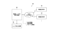
- FIG. 11 is a diagram illustrating an example of a system that implements a method for designing a progressive-power lens according to one embodiment of the present invention.
- the system 50 shown in FIG. 11 includes a plurality of spectacle store terminals and a spectacle lens pair design device (hereinafter, also referred to as a design device or a computer device) 60 of a progressive power lens that is a spectacle lens.
- a control unit not shown.
- the spectacle store terminal includes a spectacle store terminal 52 and a spectacle store terminal 54.
- the spectacle store terminals 52 and 54 are connected to the design device 60 via a WAN (Wide Area Network) or the Internet.
- the design device 60 is connected to the lens processing device 56, and the design information of the progressive-power lens designed by the design device 60 is sent to the lens processing device 56.
- a progressive power lens is manufactured by processing the lens surface based on the design information.
- the design device 60 designs the progressive-power lens 10 using the transmitted information.
- Information for manufacturing the progressive power lens 10 includes prescription information on the eyes of the wearer who is going to wear the progressive power lens 10, product information of the progressive power lens, and mounting of the progressive power lens. At least frame information.
- the prescription information includes, for example, a spherical power (also referred to as an average power) S at a distance reference point of the right-eye lens 10R and the left-eye lens 10L, a cylindrical power C at the distance reference point, an astigmatic axis Ax, and a progressive-power lens.
- a spherical power also referred to as an average power
- S a distance reference point of the right-eye lens 10R and the left-eye lens 10L
- a cylindrical power C at the distance reference point
- an astigmatic axis Ax an astigmatic axis Ax
- a progressive-power lens ADD, prism power and base direction, interpupillary distance PD, physiological features related to the visual perception of the wearer, visual environment, and the like.
- Product information includes design type information, progressive zone length information, lens diameter information, lens wall thickness information, and the like regarding lenses.
- the design type is information such as a lens that emphasizes far vision, a lens that emphasizes near vision, and a lens that is hard-designed or a software-designed lens.
- the frame information includes various information such as the shape and size of the frame lens, the frame material, the position of the eye point, the frame forward tilt angle, the frame warpage angle, and the distance between vertices.
- FIG. 12 is a configuration diagram showing a device configuration of a design device in a system for implementing the method for designing a progressive-power lens according to one embodiment of the present invention.
- the design device 60 is configured by a computer including a CPU 62, a ROM 64, a RAM 66, and a communication unit 68.
- the communication unit 68 is connected to the spectacle store terminals 52 and 54 via a WAN or the Internet.
- the computer executes the method of manufacturing the progressive-power lens as the design device 60.
- An input operation unit 70 such as a mouse and a keyboard, and a display 71 are connected to the design device 60.
- An operator inputs parameters and information via the input operation unit 70 in accordance with an input screen displayed on the display 71, so that a design described later can be executed.
- the design device 60 calls up the program stored in the ROM 64 and executes the program, whereby the software module 72 is formed and activated.
- the software module 72 includes an integrated lens design unit 72a, a target object plane setting unit 72b, a lens pair design unit 72c, a reference lens design unit 72d, a visual line calculation unit 72e, a determination unit 72f, a surface shape adjustment unit 72g, and a lens surface design. Part 72h.
- the integrated lens designing unit 72a designs the integrated eye 12M and the integrated ophthalmic lens 10M illustrated in FIG. 10 and creates the surface average power distribution and the surface astigmatism distribution of the integrated ophthalmic lens 10M illustrated in FIG.
- the target object plane setting unit 72b is a part that determines the finite distance when the wearer gazes at the target object plane 22 (actual plane 22) finite distance from the progressive power lens 10, and sets the actual plane 22. .
- the lens pair design unit 72c is a unit that performs initial design of the right-eye lens and the left-eye lens based on the above-described prescription information.
- the lens surface shape determined based on the prescription information is set as the initial design.
- the reference lens design unit 72d designs a reference single focus lens.
- a reference point single focus lens adopting the same equivalent spherical power (S + C / 2) as a single focus lens and a progressive power lens will be exemplified.
- the reference lens design unit 72d may be used also when a lens having a spherical power of zero, that is, a zero-power lens is used instead of the reference single focus lens. When the state of the naked eye is adopted, the reference lens designing unit 72d may not be used. Of course, other parts for obtaining the difference W are used even when the state of the naked eye is adopted.
- the line-of-sight calculation unit 72e passes through the right-eye lens and the left-eye lens, which are progressive power lenses that were initially designed, through the point O (FIGS. 8A and 8C) on the actual surface 22 and the point P on the side thereof (FIGS. This is a part for calculating the direction of the line of sight of the right eye 12R and the direction of the line of sight of the left eye 12L when gazing at FIG. 8D).
- the line-of-sight calculation unit 72e also calculates the direction of the line of sight of the integrated eye 12M when gazing at the point O on the actual surface 22 and the point P on the side thereof through the integrated eye 12M and the integrated ophthalmic lens 10M shown in FIG. I do.
- the line-of-sight calculation unit 72e also determines the direction of the line of sight of the right eye 12R and the direction of the left The direction of the line of sight of the eye 12L is calculated.
- the determination unit 72f determines whether or not the difference V approaches the difference W. For example, it is determined whether or not the difference V falls within a predetermined allowable range from the difference W.
- the surface shape adjustment unit 72g adjusts the lens surface shapes of the initially designed right-eye lens and left-eye lens when the determination unit 72f outputs an NG determination result.
- the design device 60 adjusts the lens surface shape using the surface shape adjustment unit 72g and the line-of-sight calculation unit 72e until the determination unit 72f outputs an OK determination result.
- the lens surface design unit 72h specifically performs the surface design on the lens surfaces on both sides by using the lens surface shape for which the determination unit 72f has output the OK determination result.
- an inner surface progressive power lens that includes a progressive component in which an addition is added to the lens surface on the eyeball side
- an outer surface progressive power lens that includes a progressive component in which an addition is added to the lens surface on the side opposite to the eyeball It is possible to appropriately select whether to perform the progressive component or to use a double-sided progressive power lens in which the progressive component is distributed to both the lens surface on the eyeball side and the lens surface on the side opposite to the eyeball side.
- FIG. 13 is a diagram showing a flow of a method for designing a progressive-power lens according to one embodiment of the present invention.
- the design device 60 receives an order for manufacturing the progressive-power lens 10 from the spectacle store terminals 52, 54 and the like (step S10).
- the order includes prescription information, product information, and frame information of a wearer who orders the progressive-power lens 10.
- the integrated lens designing unit 72a virtualizes the integrated eye 12M using the prescription information included in the received order and further using the product information. Then, as shown in FIG. 9, the integrated eye lens 10M for the integrated eye 12M is designed (step S12).
- the target object plane setting unit 72b sets a finite distance and sets the target object plane 22 (actual plane 22) (Step S14).
- FIG. 14 is a diagram illustrating an example of the surface astigmatism distribution of the right-eye lens 210R and the left-eye lens 210L that is initially designed while inwardly adjusting the surface astigmatism distribution of the integrated ophthalmic lens. .
- the lens pair design unit 72c performs an initial design of the progressive power lens for the right eye and the left eye (step S16). In addition, as shown in FIG. 14, the lens pair design unit 72c performs inward adjustment on the integrated ophthalmic lens 10M to create a surface average power distribution and a surface astigmatism distribution.
- the lens pair design unit 72c may determine the surface average power distribution and surface astigmatism of the initially designed right-eye and left-eye lenses according to the right- and left-eye cylindrical powers C and the addition ADD. The aberration distribution is corrected, and the lens surface shape that realizes the correction result is determined.
- the gaze calculation unit 72e determines that the gaze of the integrated eye 12M reaches when the integrated eye 12M sees a portion corresponding to a predetermined distance (for example, 40 cm) from the wearer on the actual surface 22 through the integrated eye lens 10M.
- the position P on the actual surface 22 to be processed is calculated (step S18).
- the position coordinates of the point O can be grasped at a stage where the predetermined distance is set to 40 cm.
- the point P is a point located at the same height in the vertical direction as the point O and located on the lateral side of the point O in the horizontal direction.
- the direction of the line of sight of the integrated eye 12M is changed by giving an inclination angle ⁇ with respect to the Z direction (depth direction) of the front view, and the line of sight at that time arrives.
- the position coordinates of the point P on the actual surface 22 are calculated.
- the line of sight is refracted by the prism action of the integrated ophthalmic lens 10M.
- the amount of refraction changes depending on which part of the integrated ophthalmic lens 10M passes.
- the inclination angle of the line of sight of the integrated eye with respect to the Z direction and the position coordinates of the point P are stored in the RAM 66.
- the line-of-sight calculation unit 72e passes the right eye 12R and the left eye 12L when the right eye 12R and the left eye 12L gaze at each point P on the actual plane 22 through the initially designed right eye lens 210R and left eye lens 210L. Then, the direction of the line of sight on the eyeball side of the left eye 12L is calculated in the same manner as the direction of the line of sight in the integrated ophthalmic lens (step S20). Then, the inclination angle of the line of sight of the right eye 12R and the left eye 12L with respect to the Z direction and the position coordinates of the point P are stored in the RAM 66.
- the line-of-sight calculation unit 72e calculates the direction of the line of sight of the right eye 12R, the left eye 12L, and the integrated eye when gazing at the point O on the median plane by the same method as the direction of the line of sight to the point P. (Step S22).
- the inclination angles of the line of sight of the right eye 12R, the left eye 12L, and the integrated eye with respect to the Z direction are stored in the RAM 66.
- the reference lens designing unit 72d designs a reference single-focal lens for the right eye and a reference single-focal lens for the left eye (step S26). This step may be performed during the execution of steps S16 to S24 in the design apparatus 60, before the execution of steps S16 to S24, or after the execution of steps S16 to S24.
- step S28 calculates a point P where the visual line of the integrated eye 12M reaches the real surface 22 (step S28). Since this step is the same as step S18 described above, this processing may be omitted. Step S28 performs the same processing as step S18, and a description thereof will be omitted.
- the line-of-sight calculation unit 72e is a line of sight when gazing at a point on the real surface 22 through the reference single focus lens, and corresponds to each point P on the real surface 22 with the right eye 12R, the left eye 12L, and The direction of the line of sight of the integrated eye 12M is calculated (step S30).
- the line-of-sight calculation unit 72e calculates the direction of the line of sight of the right eye 12R and the left eye 12L when gazing at the point O on the actual surface 22 through the reference single focus lenses 30L and 30R (step S32). Specifically, the line-of-sight calculation unit 72e calculates the inclination angle of the line of sight of the left eye 12L and the right eye 12R with respect to the Z direction. The position coordinates of the point O and the calculated inclination angles of the line of sight of the left eye 12L and the right eye 12R are stored in the RAM 66.
- steps S16 to S22 and steps S26 to 32 is not particularly limited. Step S26 may be performed after step S16, and then step 18 may be performed, and then step S28, step S20, step S30,... May be performed alternately. (4) The order of the processes in step S14 and steps S16 and S26 may be reversed.
- the determination unit 72f calls the inclination angle indicating the direction of each line of sight stored from the RAM 66 and the position coordinates of the location O, calculates the difference between the directions of each line of sight, and makes the determination (step S34). This determination is made for each point P.
- the same operation may be performed by changing the predetermined distance from 40 cm to grasp the point O, calculate each point P, and calculate the direction of the line of sight of the right eye, the left eye, and the integrated eye.
- the determination unit 72f also performs determination for each location P when the predetermined distance is changed from 40 cm.
- the surface shape adjustment unit 72g adjusts the lens surface shapes of the initially designed left-eye lens 210L and right-eye lens 210R (step S36).
- the adjusted lens surface shape is determined as the lens surface shape used for the final progressive power lens 10.
- FIG. 15 is a diagram showing an example of changes in the surface average power distribution and the surface astigmatism distribution on the lens surface before and after the adjustment when the left-eye lens 210L and the right-eye lens 210R are progressive-power lenses.
- the lens surface design unit 72h performs surface evaluation on both surfaces of the progressive-power lens. Design is performed (step S38).
- the information on the surface design of both surfaces is sent to the lens processing device 56, and the actual progressive power lens 10 is manufactured.
- the present invention also has technical significance as a design system for a progressive-power lens.
- the specific configuration is as follows. Note that in the various categories according to one embodiment of the present invention, any of the preferable examples described above may be appropriately combined. "When wearing a progressive power lens, A state A when viewing the object at a point O on the median plane of the wearer finite distance ahead of the wearer, In a plane parallel to the frontal plane and including the point O, a state B when the object at the point P located horizontally on the side of the point O at a constant height in the vertical direction relative to the point O is viewed.
- a progressive power lens design system comprising a software module for adjusting a surface shape of the progressive power lens so as to approach a difference W from a state D when an object at a position P is visually recognized.
- the present invention also has technical significance as a program (hereinafter, also simply referred to as a program) related to a system for designing a progressive-power lens.
- the specific configuration is as follows. "When wearing a progressive power lens, A state A when viewing the object at a point O on the median plane of the wearer finite distance ahead of the wearer, In a plane parallel to the frontal plane and including the point O, a state B when the object at the point P located horizontally on the side of the point O at a constant height in the vertical direction relative to the point O is viewed.
- the method for manufacturing a progressive-power lens according to one embodiment of the present invention includes a design step of performing the above-described progressive-power lens design method, and a processing step of obtaining the progressive-power lens after the design step.
- Known contents may be adopted as specific contents of the manufacturing method.
- the present invention has technical significance as a progressive-power lens.
- the specific configuration is as follows. "The near portion having refractive power used for near vision, the far portion having refractive power for viewing an object farther than near vision, and the refractive power between the far portion and the near portion.
- An intermediate portion having a progressively changing progressive action, and a progressive power lens comprising: With a prism action adjustment area that approximates the degree of image distortion due to unnecessary prism action caused by the progressive action when the reference single focus lens corresponding to the progressive power lens is worn or when the naked eye is used. Progressive power lens.
- the degree of distortion of an image due to unnecessary prism action due to the progressive action refers to, for example, the distortion in the depth direction and the depth direction in the contents described with respect to [Design method of progressive power lens according to one embodiment of the present invention]. And / or vertical eye difference.
- the prism action adjustment area preferably includes a lateral area deviated in the horizontal direction from the main gazing line.
- the position of the predetermined horizontal section is preferably a position where 85% to 100% of the addition is achieved.
- the progressive-power lens according to one embodiment of the present invention preferably satisfies at least one of the following two conditions, and more preferably satisfies both conditions.
- one embodiment of the present invention is a pair of progressive-power lenses
- an object is visually recognized through the pair of progressive-power lenses.
- the difference between the vertical prismatic power of the point ⁇ on the right-eye lens through which the line of sight of the right eye passes and the vertical prismatic power of the point ⁇ on the left-eye lens through which the line of sight of the left eye passes. Is the surface prism difference in the vertical direction.
- the method for obtaining the vertical surface prism difference when a pair of progressive power lenses is used is as follows.
- “normalized by the addition” means that the refractive power of the lens surface prism is divided by the addition set for the lens.
- all specific numerical limits of the prism power (prism refracting power) are values normalized by the addition.
- the “vertical surface prism difference normalized by the addition power” is described in the following paragraph as an example, and is described as “the vertical prism power normalized at the predetermined position ⁇ by the addition power ( A value obtained by subtracting the vertical prism power (surface prism power) normalized by the addition at the predetermined location ⁇ from the surface prism power).
- a value obtained by subtracting the vertical prism power at the predetermined location ⁇ from the vertical prism power at the predetermined location ⁇ is defined as a vertical surface prism difference at the predetermined location ⁇ .
- [Condition 1] can be defined if the left and right lenses have the same prescription power. This is because when the prescription power is the same for the left and right lenses, the right eye lens is made mirror symmetrical (left and right symmetric when viewed from the front as shown in FIG. 17 to be described later), so that the left eye lens becomes one progressive lens. This is because the predetermined area ⁇ and the predetermined area ⁇ can be set on the refractive power lens. The following expression was created based on this idea.
- the origin is defined as the midpoint between the two hidden marks on the progressive-power lens, and in the lens surface prism refractive power distribution normalized by the addition to the progressive-power lens, a horizontal position away from the main line of sight at a predetermined point ⁇ .
- the direction x and the distance d are specified.
- a predetermined location ⁇ that is 2d away from the predetermined location ⁇ in the direction ⁇ x opposite to the direction x is specified.
- a value obtained by subtracting the vertical prism power at the predetermined location ⁇ from the vertical prism power at the predetermined location ⁇ is defined as a vertical surface prism difference at the predetermined location ⁇ .
- the difference between the maximum value and the minimum value of the vertical surface prism difference is 0.2.
- the progressive-power lens of [prism diopter / diopter] or more is a feature not found in conventional progressive-power lenses. This is because, in one embodiment of the present invention, this is intentionally set in order to reduce the vertical eye difference.
- one embodiment of the present invention is a pair of progressive-power lenses
- an object is visually recognized through the pair of progressive-power lenses.
- the difference between the horizontal prism frequency of the point ⁇ on the right-eye lens through which the line of sight of the right eye passes and the horizontal prism frequency of the point ⁇ on the left-eye lens through which the line of sight of the left eye passes Is the horizontal surface prism difference.
- the method of obtaining the horizontal surface prism difference when using a pair of progressive power lenses is as follows.
- the origin is defined as the midpoint between the two hidden marks on the progressive-power lens, and in the lens surface prism refractive power distribution normalized by the addition to the progressive-power lens, the near-end portion on a predetermined horizontal section
- the value obtained by subtracting the horizontal prism power at the predetermined location ⁇ from the horizontal prism power at the predetermined location ⁇ is defined as the surface prism difference in the horizontal direction.
- ⁇ [Condition 2] can be defined when the prescription power is the same for the left and right lenses, even if a single progressive power lens is used instead of a pair of progressive power lenses. Because, when the prescription power is the same in the left and right lenses, the right eye lens is left and right symmetrical to be the left eye lens, and the predetermined area ⁇ and the predetermined area ⁇ can be set on one progressive power lens. That's why. The following expression was created based on this idea.
- the origin is defined as the midpoint between the two hidden marks on the progressive-power lens, and in the lens surface prism refractive power distribution normalized by the addition to the progressive-power lens, the near-end portion on a predetermined horizontal section
- the absolute value of twice the value of the prism power in the horizontal direction at the predetermined location ⁇ is defined as the horizontal surface prism difference at the predetermined location ⁇ .
- the plot of the progressive-power lens is when the reference single-focal lens corresponding to the progressive-power lens is worn. Or, it does not intersect with the plot corresponding to the naked eye.
- [Condition 3] this is a condition mainly related to reduction of distortion in the depth direction. Therefore, [Condition 3] may be applied instead of [Condition 2] relating to the reduction of distortion in the depth direction, or both [Condition 2] and [Condition 3] may be applied.
- the plot of the progressive-power lens when the horizontal axis is the direction of the line of sight (tan ⁇ ) and the vertical axis is the depth direction position information (unit: diopter) is the progressive-power lens.
- the fact that the plot does not intersect with the plot when the corresponding reference single focus lens is worn or when the eye is equivalent to the naked eye indicates the following.
- the reference lens or the lens of one embodiment of the present invention when compared with the other lens, the image of the object obtained through the lens is always in the depth direction or the front direction. Indicates that it exists in one of the directions. This contributes to a reduction in distortion in the depth direction. As a result, the influence caused by unnecessary prism action due to the progressive action is reduced, and a comfortable wearing feeling is obtained.
- a pair of progressive-power lenses (hereinafter, a pair of spectacle lenses) was manufactured.
- the pair of spectacle lenses manufactured in each example has the following configuration.
- a progressive-power lens pair consisting of a right-eye lens and a left-eye lens
- the right-eye lens and the left-eye lens of the progressive-power lens pair are a distance portion with a power set for viewing far away, and a near power with additional power added to the distance power for looking near.
- the near portion includes a portion where is set, and an intermediate portion whose power progressively changes between the far portion and the near portion.
- the right-eye lens and the left-eye lens cause distortion of an image caused by the difference between the prism action of the spectacle lens, specifically, the difference between the prism actions of the left-eye lens and the right-eye lens.
- a prism adjustment area is provided for approximating the prism action of the lens surface shape of the reference lens set based on the power, specifically, image distortion caused by the difference in the prism action.
- the prism adjustment area includes an area for realizing the near power, the near reference point of each lens for the right eye lens and the left eye lens, and the right eye lens and the left eye on a horizontal line passing through the near reference point.
- the ophthalmic lens includes a region other than a vertical line passing through the midpoint of two hidden marks provided on each lens.
- FIG. 16 is a diagram illustrating an example of a spectacle lens 300 for the right eye in the spectacle lens pair of each embodiment.
- FIG. 16 shows the hidden marks 302 and 304.
- the hidden marks 302 and 304 are specified by JIS and are alignment reference marks.
- the hidden marks 302 and 304 are provided at two points 17 mm apart from the center of the lens in the horizontal direction. Therefore, the horizontal direction of the spectacle lens 300 and the vertical direction perpendicular thereto can be determined by the hidden marks 302 and 304.
- the midpoint 306 of the hidden marks 302, 304 coincides with the center of the spectacle lens 300.
- the main gaze passes through the midpoint 306 in the vertical direction.
- the near reference point 308 is located at a position shifted vertically downward from the midpoint 306 to the nose side in the horizontal direction, and is usually specified by the manufacturer. For example, in the case of a progressive power lens having a spherical power S of 0.00D and an addition ADD of 2.50D and a progressive zone length of 14 mm, the near reference point 308 is 14 mm vertically downward from the midpoint 306. And at a position moved 2.5 mm to the nose side in the horizontal direction.
- the prism adjustment area includes an area (a near power measurement circle) for realizing a near power (a power obtained by adding an additional power ADD to the spherical power S of the far portion), and includes a near reference point 308 and a near reference point. It includes left and right regions other than the vertical line VL passing through the midpoint 306 on the horizontal line HL passing through 308. Since this region is a part of the near portion and is used when viewing the lower side, distortion of the image in the depth direction due to the difference in the prism action with respect to the line of sight of each of the left eye and the right eye is likely to occur. . Therefore, the prism adjustment region includes left and right regions other than the vertical line VL on the horizontal line HL.
- the prism adjustment region includes a near reference point.
- the addition ADD or the reference addition indicated by the manufacturer is 100%.
- the prism adjustment region includes a near reference point because the user can easily feel a comfortable wearing feeling.
- FIG. 17 is a diagram illustrating a method of calculating the distribution of the difference value from the lens surface prism refractive power distribution in the right-eye lens 300 and the left-eye lens 400.
- the refractive power of the lens surface prism normalized by the addition ADD is the inclination in the vertical direction ⁇ (refractive index of lens material ⁇ 1) ⁇ 100 [prism Dio on one of the lens surfaces on both sides of one lens. Putli] / addition power ADD [diopter].
- the slope is a dimensionless value.
- the origin of the lens surface prism power distribution is the midpoint 306.
- the vertical distribution of the lens surface prism power distribution of the right eye lens 300 on a horizontal cross section in the near portion of the right eye lens 300 and the left eye lens 400 is shown.
- the distribution of the difference value (the vertical surface prism difference, hereinafter the same) between the directional component and the vertical component of the lens surface prism refractive power distribution of the left-eye lens 410 is represented by the origin (middle point 306). , A midpoint 406), and a first region and a second region are divided by a vertical line.
- the near portion may be, for example, regions 310 and 410 within a range separated by a predetermined distance upward and downward in the vertical direction around the near reference points 308 and 408.
- the predetermined distance is, for example, a distance in a range of 2.5 to 4 mm.
- the difference value is the normalized value of the refractive power of the lens surface prism at positions 312 and 412 at the same distance from the origin (middle points 306 and 406) to the same side (right or left) in the horizontal direction. This is the difference.
- the value of the normalized lens surface prism power distribution of the left-eye lens 400 is subtracted from the value of the normalized lens surface prism power distribution of the right-eye lens 300.
- the first region is, for example, a difference value in a region on the right side of a vertical line passing through the origin (middle point 306) of the right-eye lens 300, specifically, horizontal from the origin (middle point 306, middle point 406).
- This is a difference value between values at positions 312 and 412 that are separated by the same distance to the right in the direction.
- the second region is, for example, a difference value in a region on the left side from a vertical line passing through the origin (middle point 306) of the right-eye lens 300, specifically, a difference value in the horizontal direction from the origin (middle point 306, middle point 406).
- the difference value at the positions 313 and 413 separated by the same distance on the left side.
- the right-eye lens 300 and the left-eye lens 400 have a minimum difference value of one region and a maximum difference value of the other region in the first region and the second region of the difference value distribution determined in this manner.
- This rule corresponds to [Condition 1] described in [Progressive power lens according to one embodiment of the present invention]. That is, in each embodiment, a pair of spectacle lenses satisfying [condition 1] is manufactured.
- Example 3 shows that specific data satisfying [condition 1] is described in Example 3. Further, it will be shown in Example 1 that the pair of spectacle lenses according to each example also satisfies [condition 2].
- Example 1 The description of the vertical axis, horizontal axis, and the like in the graphs and the like shown in the first embodiment has the same contents in the same kind of drawings in the other embodiments, and thus the description in the other embodiments is omitted. “Graph” in the present specification may be read as “plot”.
- the spherical power S is 0.00D [diopter]
- the addition ADD is 2.50D [diopter]
- the corridor length is 14 mm
- the refractive index is 1.60. did.
- the distance reference point is a position shifted 8 mm vertically upward from the eyeglass lens center 240
- the near reference point is a position shifted 14mm vertically downward from the eyeglass lens center 240 and 2.5mm to the horizontal nose side.
- FIG. 18A shows the difference in the direction of the line of sight between the eyes in the vertical direction when the spectacle lens pair is manufactured, the lens of Example 1, and the conventional lens are worn, that is, the vertical direction.
- the horizontal axis represents the horizontal component of the line of sight
- the vertical axis represents the vertical component of the line of sight.
- FIG. 18B is a graph illustrating a change in an apparent position of the target object plane 22 in the depth direction, that is, a distortion in the depth direction.
- the vertical axis indicates depth direction position information [diopter], and the horizontal axis indicates the horizontal direction.
- the direction of the line of sight [tan ⁇ ] is shown.
- each distribution diagram shown in FIG. 18A indicates the eyeglass lens center 240 (prism measurement point).
- the position on the horizontal axis and the vertical axis of each distribution diagram shown in FIG. 18A indicates the direction of the line of sight as viewed from the midpoint M of the center of both eyes.
- FIG. 19A is a view for explaining the direction of the horizontal line of sight which is the horizontal axis in FIG. 18B.
- the angle between the direction and the direction is ⁇
- the direction of the line of sight in the horizontal direction is indicated by tan ⁇ .
- ⁇ 48 degrees
- the level of the contour line is obtained by calculating the vertical eye position difference between the eyes (the direction of the line of sight of the left eye minus the direction of the line of sight of the right eye) in units of prism diopters. Is shown. In each distribution chart, the smaller the absolute value is, the smaller the vertical eye position difference is.
- the distribution of the spectacle lens of Example 1 is larger than that of the conventional spectacle lens. It shows that it is close to the distribution.
- FIG. 19B is a diagram illustrating position information in the depth direction, which is the vertical axis in FIG. 18B.
- the reference intersection O which can be seen through the lens using the angle (convergence angle) of the direction of the line of sight between the eyes when gazing at the reference intersection O and the information on the interpupillary distance PD.
- the distance Rc in the depth direction is calculated.
- the distance Ro in the depth direction of the intersection P seen through the lens is calculated using the angle of the line of sight from the front view direction and the information on the interpupillary distance PD when gazing at the intersection P through the lens.
- the distance Rc and the distance Ro are distances based on a point at which a vertical plane passing through the center of the integrated eye 12M and the reference intersection O intersects with the lens 10M for the integrated eye.
- the position information [diopter] in the depth direction which is the vertical axis of the graph shown in FIG. 18B, indicates Dc-Do.
- Dc-Do is smaller, it means that the apparent position in the depth direction of the intersection P does not relatively deviate from the apparent position in the depth direction when gazing at the reference intersection O.
- the position of the lens in Example 1 in the depth direction is different. It can be seen that the change amount ⁇ 1 is smaller than the change amount ⁇ 2 of the conventional lens.
- the small change amount ⁇ 1 indicates that the change in the apparent position in the depth direction of the apparent target object plane 20 seen through the lens due to the position along the horizontal direction is small. Therefore, the wearer wearing the spectacle lens pair 10 of the first embodiment is less likely to feel the image distortion in the depth direction, and can further reduce the uncomfortable feeling of wearing.
- the plot does not intersect when the reference single focus lens corresponding to the progressive-power lens is worn or when it is equivalent to the naked eye. That is, the lens of Example 1 satisfies [Condition 3]. This is the same in the lens of Example 2 described later.
- Example 1 the above [Condition 2] was examined.
- the surface prism difference in the horizontal direction between the lens of Example 1 and the conventional lens is summarized.
- the lens of Example 1 can align the direction of the vertical line of sight between both eyes like the reference lens. . As a result, it was found that the unpleasant wearing feeling given to the wearer can be reduced.
- the spherical power S is ⁇ 4.00 D [diopter]
- the addition ADD is 2.50 D [diopter]
- the corridor length is 14 mm
- the refractive index is 1.60.
- the distance reference point is a position moved 8 mm vertically upward from the eyeglass lens center 240
- the near reference point is a position moved 14mm vertically downward from the eyeglass lens center 240 and 2.3mm to the horizontal nose side.
- FIG. 21A shows the difference in the direction of the line of sight between the two eyes in the vertical direction when the spectacle lens pair is manufactured, the lens of Example 2, and the conventional lens are worn, that is, the vertical direction.
- the horizontal axis represents the horizontal component of the line of sight
- the vertical axis represents the vertical component of the line of sight.
- FIG. 21B is a graph illustrating a change in an apparent position of the target object plane 22 in the depth direction, that is, a distortion in the depth direction.
- the vertical axis indicates depth direction position information [diopter], and the horizontal axis indicates the horizontal direction.
- the direction of the line of sight [tan ⁇ ] is shown.
- the distribution of the spectacle lens according to the second embodiment is larger than the distribution of the conventional spectacle lens. It shows that it is close to the distribution.
- the position of the target object plane 22 in the depth direction is different from that of the reference lens, the position of the lens in Example 2 in the depth direction is different. It can be seen that the amount of change is smaller than the amount of change in the conventional lens.
- the lens of Example 2 can align the direction of the vertical line of sight between both eyes like the reference lens. . As a result, it was found that the unpleasant wearing feeling given to the wearer can be reduced.
- the spherical power S is 0.00D [diopter]
- the addition ADD is 2.50D [diopter]
- the corridor length is 14 mm
- the refractive index is 1.60. did.
- the distance reference point is a position shifted 8 mm vertically upward from the eyeglass lens center 240
- the near reference point is a position shifted 14mm vertically downward from the eyeglass lens center 240 and 2.5mm to the horizontal nose side.
- the minimum difference value of one area and the maximum difference value of the other area are different.
- the absolute value of the difference is not less than 0.2 [prism diopter / diopter].
- the absolute value of the difference between the minimum difference value and the maximum difference value is less than 0.2 [prism diopter / diopter].
- the absolute value of the difference between the minimum difference value and the maximum difference value of the progressive-power lens according to the third embodiment is larger than that of the conventional progressive-power lens according to the progressive power lens according to one aspect of the present invention.
- the lens surface shape was adjusted by employing the method of designing a refractive power lens. Specifically, this is because the difference in the prism action with respect to the line of sight of each of the left and right eyes has been adjusted.
- the spectacle lens pair of the progressive-power lens a region in the left direction with the origin (middle point 306) of the right eye lens 300 interposed therebetween and a region in the left direction with the origin (middle point 406) of the left eye lens 400 interposed therebetween.
- the difference of the prism action at the same distance from the origin is increased as compared with the conventional pair of spectacle lenses, and similarly, the region in the right direction across the origin (middle point 306) of the right eye lens 300 and the left eye lens 400 This is because the difference in the prism action at the same distance from the origin in the region to the right with respect to the origin (middle point 406) is increased as compared with the conventional pair of spectacle lenses.
- the positions of the regions 310 and 410 for obtaining the distribution of the difference values shown in FIG. 21 are positions where 85% to 100% of the addition ADD is achieved.
- This region is particularly a region in which image distortion or an unpleasant wearing sensation caused by the difference in the prism action is easily felt, so that the effect of improving the image distortion or the unpleasant wearing sensation is increased.
- One embodiment of the present disclosure is as follows.
- a state A when viewing the object at a point O on the median plane of the wearer finite distance ahead of the wearer, In a plane parallel to the frontal plane and including the point O, a state B when the object at the point P located horizontally on the side of the point O at a constant height in the vertical direction relative to the point O is viewed.
Landscapes
- Health & Medical Sciences (AREA)
- Ophthalmology & Optometry (AREA)
- Physics & Mathematics (AREA)
- General Health & Medical Sciences (AREA)
- General Physics & Mathematics (AREA)
- Optics & Photonics (AREA)
- Eyeglasses (AREA)
Abstract
Description
図1は、天地の天の方向(鉛直上方)から天地の地の方向(鉛直下方)を見たときの、従来の累進屈折力レンズである右眼用レンズ10R及び左眼用レンズ10L、ならびに、眼鏡レンズ10を通して見える、装用者にとっての見かけの目標物体面20の位置を示す概略図である。以降、見かけの目標物体面20のことを「見かけ面20」とも称する。
図3は、水平方向から見たときの、従来の累進屈折力レンズである右眼用レンズ10R及び左眼用レンズ10Lを通して近方距離且つ側方にある物体を見たときの、右眼Rと左眼Lとで上下方向の眼位差が生じている様子を示す図である。
本発明の第1の態様は、
累進屈折力レンズの装用時における、
装用者から有限距離前方且つ装用者の正中面上の箇所Oの物体を視認するときの状態Aと、
前頭面と平行な面であって箇所Oを含む面内にて、箇所Oと鉛直方向の高さ一定で箇所Oの水平方向側方に位置する箇所Pの物体を視認するときの状態Bとの差Vを、
累進屈折力レンズに対応する参照用単焦点レンズの装用時又は裸眼相当時における、
箇所Oの物体を視認するときの状態Cと、
箇所Pの物体を視認するときの状態Dとの差Wに近づけるよう、累進屈折力レンズの表面形状を調整する、累進屈折力レンズの設計方法である。
差Vは、状態Aでの右眼の視線の向きと左眼の視線の向きとの角度差VAと、状態Bでの右眼の視線の向きと左眼の視線の向きとの角度差VBとの差であり、
差Wは、状態Cでの右眼の視線の向きと左眼の視線の向きとの角度差WCと、状態Dでの右眼の視線の向きと左眼の視線の向きとの角度差WDとの差であり、
累進屈折力レンズの表面形状を調整して状態Bでの角度差VBを変動させることにより、差Wからの所定の許容範囲内に差Vを収める。
装用者の正中面上且つ右眼と左眼の中間位置に回旋中心を設定した統合眼及び統合眼用の累進屈折力レンズを仮想したとき、
角度差VAは、状態Aでの、右眼の視線の向きと統合眼の視線の向きとの角度差VARと、左眼の視線の向きと統合眼の視線の向きとの角度差VALとの差であり、
角度差VBは、状態Bでの、右眼の視線の向きと統合眼の視線の向きとの角度差VBRと、左眼の視線の向きと統合眼の視線の向きとの角度差VBLとの差であり、
角度差WCは、状態Cでの、右眼の視線の向きと統合眼の視線の向きとの角度差WCRと、左眼の視線の向きと統合眼の視線の向きとの角度差WCLとの差であり、
角度差WDは、状態Dでの、右眼の視線の向きと統合眼の視線の向きとの角度差WDRと、左眼の視線の向きと統合眼の視線の向きとの角度差WDLとの差である。
角度差VARと角度差VALの比、角度差VBRと角度差VBLの比、角度差WCRと角度差WCLの比、及び角度差WDRと角度差WDLの比の少なくともいずれかに応じ、累進屈折力レンズの表面形状の調整の際の、右眼用の累進屈折力レンズに対する補正量と左眼用の累進屈折力レンズに対する補正量とを按分する。
統合眼用の累進屈折力レンズの等価球面度数として、右眼用の累進屈折力レンズの等価球面度数と、左眼用の累進屈折力レンズの等価球面度数との平均値を採用する。
差Wからの所定の許容範囲は、差Wの50%以内である。
第1~第6のいずれかに記載の累進屈折力レンズの設計方法を行う設計工程と、
設計工程後、累進屈折力レンズを得る加工工程と、
を有する、累進屈折力レンズの製造方法である。
累進屈折力レンズの装用時における、
装用者から有限距離前方且つ装用者の正中面上の箇所Oの物体を視認するときの状態Aと、
前頭面と平行な面であって箇所Oを含む面内にて、箇所Oと鉛直方向の高さ一定で箇所Oの水平方向側方に位置する箇所Pの物体を視認するときの状態Bとの差Vを、
累進屈折力レンズに対応する 参照用単焦点レンズの装用時又は裸眼相当時における、
箇所Oの物体を視認するときの状態Cと、
箇所Pの物体を視認するときの状態Dとの差Wに近づけるよう、累進屈折力レンズの表面形状を調整するソフトウェアモジュールを備えた、累進屈折力レンズの設計システムである。
近方視に用いる屈折力を有する近用部と、近方視よりも遠方の物体を見るための屈折力を有する遠用部と、遠用部と近用部との間で屈折力が累進的に変化する累進作用を有する中間部と、を備える累進屈折力レンズであって、
累進作用に起因する不必要なプリズム作用による像の歪み度合いを、累進屈折力レンズに対応する参照用単焦点レンズの装用時又は裸眼相当時における像の歪み度合いに近づけるプリズム作用調整領域を備える、累進屈折力レンズである。
プリズム作用調整領域は、主注視線から水平方向に外れた側方部の領域を含む。
以下の2つの条件の少なくともいずれかを満たす。
[条件1]
レンズ水平方向を横軸、加入度で正規化された鉛直方向の表面プリズム差分を縦軸としたときのプロットにおいて、近用部における所定の水平断面上での所定箇所αの鉛直方向の表面プリズム差分の最大値と最小値の差が0.2[プリズムディオプトリ/ディオプター]以上である。
[条件2]
レンズ水平方向を横軸、加入度で正規化された水平方向の表面プリズム差分を縦軸としたときのプロットにおいて、近用部における所定の水平断面上での所定箇所γ内のx=0の位置において、水平方向の表面プリズム差分の絶対値が0.25[プリズムディオプトリ/ディオプター]以上であり、所定箇所γ内のx=0の位置は、プリズム参照点の真下または累進屈折力レンズの2つのアライメント基準マークの中点の真下に位置する。
所定の水平断面の位置は、加入度の85%から100%が達成される位置である。
[条件3]
横軸を視線の向き(tanθ)、縦軸を奥行き方向位置情報(単位:ディオプター)としたときの、累進屈折力レンズのプロットが、累進屈折力レンズに対応する参照用単焦点レンズの装用時又は裸眼相当時のプロットと交差しない。
本発明の一態様に係る累進屈折力レンズの設計方法の具体的な構成は以下の通りである。
「累進屈折力レンズの装用時における、
装用者から有限距離前方且つ装用者の正中面上の箇所Oの物体を視認するときの状態Aと、
前頭面と平行な面であって箇所Oを含む面内にて、箇所Oと鉛直方向の高さ一定で箇所Oの水平方向側方に位置する箇所Pの物体を視認するときの状態Bとの差Vを、
累進屈折力レンズに対応する参照用単焦点レンズの装用時又は裸眼相当時における、
箇所Oの物体を視認するときの状態Cと、
箇所Pの物体を視認するときの状態Dとの差Wに近づけるよう、累進屈折力レンズの表面形状を調整する、累進屈折力レンズの設計方法。」
以下、本発明の一態様の更なる具体例、好適例及び変形例について説明する。
差Wは、状態Cでの右眼の視線の向きと左眼の視線の向きとの角度差WCと、状態Dでの右眼の視線の向きと左眼の視線の向きとの角度差WDとの差である。
「角度差VAは、図8Aに示す累進正面視状態Aでの、右眼の視線の向きと統合眼の視線の向きとの角度差VARと、左眼の視線の向きと統合眼の視線の向きとの角度差VALとの差であり、
角度差VBは、図8Bに示す累進側方視状態Bでの、右眼の視線の向きと統合眼の視線の向きとの角度差VBRと、左眼の視線の向きと統合眼の視線の向きとの角度差VBLとの差であり、
角度差WCは、図8Cに示す参照正面視状態Cでの、右眼の視線の向きと統合眼の視線の向きとの角度差WCRと、左眼の視線の向きと統合眼の視線の向きとの角度差WCLとの差であり、
角度差WDは、図8Dに示す参照側方視状態Dでの、右眼の視線の向きと統合眼の視線の向きとの角度差WDRと、左眼の視線の向きと統合眼の視線の向きとの角度差WDLとの差である。」
「角度差VARと角度差VALの比、角度差VBRと角度差VBLの比、角度差WCRと角度差WCLの比、及び角度差WDRと角度差WDLの比の少なくともいずれかに応じ、累進屈折力レンズの表面形状の調整の際の、右眼用の累進屈折力レンズに対する補正量と左眼用の累進屈折力レンズに対する補正量とを按分する。」
同様に、図8Cに示す参照正面視状態Cでの、右眼の視線の向きと統合眼の視線の向きとの角度差WCRと、図8Dに示す参照側方視状態Dでの、右眼の視線の向きと統合眼の視線の向きとの角度差WDRとの差WRを得る。
そして、差VRが差WRに近づくように累進屈折力レンズを設計する。これにより、右眼用レンズは、累進作用に起因する不必要なプリズム作用により生じる影響が小さくなる。
本発明の一態様では、累進正面視状態Aと累進側方視状態Bとの差Vを把握し、参照正面視状態Cと参照側方視状態Dとの差Wを把握し、差Vが差Wに近づくようにレンズ表面形状を設計する場合を例示した。
以下、上記の累進屈折力レンズの設計方法をシステムに応用した一具体例を記載する。本例では統合眼を採用する場合について例示する。なお、これまでに述べた内容と重複する内容については記載を省略する。また、本例では右眼用レンズと左眼用レンズとを設計する場合を例示するため、説明の便宜上、両レンズをまとめてレンズ対と表現する場合もある。また、参照用単焦点レンズを参照用レンズ、統合眼用レンズを統合レンズと表現する場合もある。
本発明は、累進屈折力レンズの設計システムとしても技術的意義がある。その具体的な構成は以下のとおりである。なお、以降、本発明の一態様に係る種々のカテゴリーは、これまでに述べた好適例を適宜組み合わせてもよい。
「累進屈折力レンズの装用時における、
装用者から有限距離前方且つ装用者の正中面上の箇所Oの物体を視認するときの状態Aと、
前頭面と平行な面であって箇所Oを含む面内にて、箇所Oと鉛直方向の高さ一定で箇所Oの水平方向側方に位置する箇所Pの物体を視認するときの状態Bとの差Vを、
累進屈折力レンズに対応する 参照用単焦点レンズの装用時又は裸眼相当時における、
箇所Oの物体を視認するときの状態Cと、
箇所Pの物体を視認するときの状態Dとの差Wに近づけるよう、累進屈折力レンズの表面形状を調整するソフトウェアモジュールを備えた、累進屈折力レンズの設計システム。」
本発明は、累進屈折力レンズの設計システムに係るプログラム(以降、単にプログラムとも称する。)としても技術的意義がある。その具体的な構成は以下のとおりである。
「累進屈折力レンズの装用時における、
装用者から有限距離前方且つ装用者の正中面上の箇所Oの物体を視認するときの状態Aと、
前頭面と平行な面であって箇所Oを含む面内にて、箇所Oと鉛直方向の高さ一定で箇所Oの水平方向側方に位置する箇所Pの物体を視認するときの状態Bとの差Vを、
累進屈折力レンズに対応する 参照用単焦点レンズの装用時又は裸眼相当時における、
箇所Oの物体を視認するときの状態Cと、
箇所Pの物体を視認するときの状態Dとの差Wに近づけるよう、累進屈折力レンズの表面形状を調整するようコンピュータ(ソフトウェアモジュール)を機能させる、累進屈折力レンズの設計システムに係るプログラム。」
本発明の一態様に係る累進屈折力レンズの製造方法は、これまでに説明した累進屈折力レンズの設計方法を行う設計工程と、該設計工程後、累進屈折力レンズを得る加工工程と、を有する。具体的な製造方法の内容は、公知の内容を採用すればよい。
本発明は、累進屈折力レンズとしても技術的意義がある。その具体的な構成は以下のとおりである。
「近方視に用いる屈折力を有する近用部と、近方視よりも遠方の物体を見るための屈折力を有する遠用部と、遠用部と近用部との間で屈折力が累進的に変化する累進作用を有する中間部と、を備える累進屈折力レンズであって、
累進作用に起因する不必要なプリズム作用による像の歪み度合いを、累進屈折力レンズに対応する参照用単焦点レンズの装用時又は裸眼相当時における像の歪み度合いに近づけるプリズム作用調整領域を備える、累進屈折力レンズ。」
レンズ水平方向を横軸、加入度で正規化された鉛直方向の表面プリズム差分を縦軸としたときのプロットにおいて、近用部における所定の水平断面上での所定箇所αの鉛直方向の表面プリズム差分の最大値と最小値の差が0.2[プリズムディオプトリ/ディオプター]以上である。
レンズ水平方向を横軸、加入度で正規化された水平方向の表面プリズム差分を縦軸としたときのプロットにおいて、近用部における所定の水平断面上での所定箇所γ内のx=0の位置において、水平方向の表面プリズム差分の絶対値が0.25[プリズムディオプトリ/ディオプター]以上である。なお、所定箇所γ内のx=0の位置は、プリズム参照点の真下または累進屈折力レンズの2つのアライメント基準マークの中点の真下に位置する。また、x=0は、プリズム参照点または該中点を含む鉛直線である。本明細書における表面プリズム差分に係るプロットのx=0の設定は、以降同様とする。
1.原点を累進屈折力レンズ上の2つの隠しマークの中点とし、累進屈折力レンズに対して加入度で正規化されたレンズ表面プリズム屈折力分布において、右眼用レンズでの(近用基準点を含みうるy=-14mmにて)主注視線から水平方向xに距離dだけ離れた所定箇所αを特定する。
2.左眼用レンズでの(近用基準点を含みうるy=-14mmにて)主注視線から上記水平方向xの逆方向-xに距離dだけ離れた所定箇所βを特定する。
3.所定箇所αにおける鉛直方向のプリズム度数から所定箇所βにおける鉛直方向のプリズム度数を差し引いた値を、所定箇所αにおける鉛直方向の表面プリズム差分とする。
1.原点を累進屈折力レンズ上の2つの隠しマークの中点とし、累進屈折力レンズに対して加入度で正規化されたレンズ表面プリズム屈折力分布において、所定箇所αの、主注視線から離れる水平方向xおよび距離dを特定する。
2.方向xの逆方向-xへと所定箇所αから距離2d離れた所定箇所βを特定する。
3.所定箇所αにおける鉛直方向のプリズム度数から所定箇所βにおける鉛直方向のプリズム度数を差し引いた値を、所定箇所αにおける鉛直方向の表面プリズム差分とする。
1.原点を累進屈折力レンズ上の2つの隠しマークの中点とし、累進屈折力レンズに対して加入度で正規化されたレンズ表面プリズム屈折力分布において、近用部における所定の水平断面上での所定箇所γ(例えばy=-14mm且つx=0)を特定する。
2.左眼用レンズでの近用部における所定の水平断面上での所定箇所δ(例えばy=-14mm且つx=0)を特定する。
3.所定箇所γにおける水平方向のプリズム度数から所定箇所δにおける水平方向のプリズム度数を差し引いた値を、水平方向の表面プリズム差分とする。
1.原点を累進屈折力レンズ上の2つの隠しマークの中点とし、累進屈折力レンズに対して加入度で正規化されたレンズ表面プリズム屈折力分布において、近用部における所定の水平断面上での所定箇所γ(例えばy=-14mm且つx=0)を特定する。
2.所定箇所γにおける水平方向のプリズム度数の2倍の値の絶対値を、所定箇所γにおける水平方向の表面プリズム差分とする。
[条件3]
横軸を視線の向き(tanθ)、縦軸を奥行き方向位置情報(単位:ディオプター)としたときの、累進屈折力レンズのプロットが、累進屈折力レンズに対応する参照用単焦点レンズの装用時又は裸眼相当時のプロットと交差しない。
以降の実施例においては、一対の累進屈折力レンズ(以降、眼鏡レンズ対)を作製した。 各実施例で作製される眼鏡レンズ対は、以下の構成を有する。
累進屈折力レンズ対の右眼用レンズと左眼用レンズは、遠くを見るための度数が設定された遠用部と、近くを見るために遠用度数に加入度が付加された近用度数が設定された部分を含む近用部と、遠用部と近用部の間で度数が累進的に変化する中間部と、を備える。
実施例1に示すグラフ等における縦軸および横軸等の説明は、別実施例での同種の図においても同内容であるため、別実施例での記載を省略する。本明細書における「グラフ」は「プロット」と読み替えても差し支えない。
眼鏡レンズ対を作製するための処方情報のうち球面度数Sは-4.00D[ディオプター]とし、加入度ADDは2.50D[ディオプター]とし、累進帯長を14mmとし、屈折率は1.60とした。
眼鏡レンズ対を作製するための処方情報のうち球面度数Sは0.00D[ディオプター]とし、加入度ADDは2.50D[ディオプター]とし、累進帯長を14mmとし、屈折率は1.60とした。
以下、本開示の「累進屈折力レンズの設計方法、製造方法、設計システム、及び累進屈折力レンズ」について総括する。
本開示の一実施例は以下の通りである。
累進屈折力レンズの装用時における、
装用者から有限距離前方且つ装用者の正中面上の箇所Oの物体を視認するときの状態Aと、
前頭面と平行な面であって箇所Oを含む面内にて、箇所Oと鉛直方向の高さ一定で箇所Oの水平方向側方に位置する箇所Pの物体を視認するときの状態Bとの差Vを、
累進屈折力レンズに対応する 参照用単焦点レンズの 装用時又は裸眼相当時における、
箇所Oの物体を視認するときの状態Cと、
箇所Pの物体を視認するときの状態Dとの差Wに近づけるよう、累進屈折力レンズの表面形状を調整する、累進屈折力レンズの設計方法。
10L 左眼用レンズ
10R 右眼用レンズ
10M 統合眼用レンズ
12L 左眼
12R 右眼
12M 統合眼
20 見かけの目標物体面(見かけ面)
22 目標物体面(実際面)
30L 右眼用の参照用単焦点レンズ
30R 左眼用の参照用単焦点レンズ
30M 統合眼用単焦点レンズ
50 システム
52,54 眼鏡店端末
56 レンズ加工装置
60 眼鏡レンズ対設計装置
62 CPU
64 ROM
66 RAM
68 通信部
70 入力操作部
71 ディスプレイ
72 ソフトウェアモジュール
72a 統合眼用レンズ設計部
72b 目標物体面設定部
72c レンズ対設計部
72d 参照用レンズ設計部
72e 視線計算部
72f 判定部
72g 表面形状調整部
72h レンズ表面設計部
100 (従来の)眼鏡レンズ対
100L (従来の)右眼用レンズ
100R (従来の)左眼用レンズ
200 主注視線
210L (初期設計した)左眼用レンズ
210R (初期設計した)右眼用レンズ
220 遠用基準点
230,308,408 近用基準点
240 眼鏡レンズ中心(プリズム測定点)
302,304 隠しマーク
306,406 中点
310,410 領域
Claims (12)
- 累進屈折力レンズの装用時における、
装用者から有限距離前方且つ装用者の正中面上の箇所Oの物体を視認するときの状態Aと、
前頭面と平行な面であって前記箇所Oを含む面内にて、前記箇所Oと鉛直方向の高さ一定で前記箇所Oの水平方向側方に位置する箇所Pの物体を視認するときの状態Bとの差Vを、
累進屈折力レンズに対応する参照用単焦点レンズの装用時又は裸眼相当時における、
前記箇所Oの物体を視認するときの状態Cと、
前記箇所Pの物体を視認するときの状態Dとの差Wに近づけるよう、累進屈折力レンズの表面形状を調整する、累進屈折力レンズの設計方法。 - 前記差Vは、前記状態Aでの右眼の視線の向きと左眼の視線の向きとの角度差VAと、前記状態Bでの右眼の視線の向きと左眼の視線の向きとの角度差VBとの差であり、
前記差Wは、前記状態Cでの右眼の視線の向きと左眼の視線の向きとの角度差WCと、前記状態Dでの右眼の視線の向きと左眼の視線の向きとの角度差WDとの差であり、
累進屈折力レンズの表面形状を調整して前記状態Bでの前記角度差VBを変動させることにより、前記差Wからの所定の許容範囲内に前記差Vを収める、請求項1に記載の累進屈折力レンズの設計方法。 - 装用者の正中面上且つ右眼と左眼の中間位置に回旋中心を設定した統合眼及び統合眼用の累進屈折力レンズを仮想したとき、
前記角度差VAは、前記状態Aでの、右眼の視線の向きと統合眼の視線の向きとの角度差VARと、左眼の視線の向きと統合眼の視線の向きとの角度差VALとの差であり、
前記角度差VBは、前記状態Bでの、右眼の視線の向きと統合眼の視線の向きとの角度差VBRと、左眼の視線の向きと統合眼の視線の向きとの角度差VBLとの差であり、
前記角度差WCは、前記状態Cでの、右眼の視線の向きと統合眼の視線の向きとの角度差WCRと、左眼の視線の向きと統合眼の視線の向きとの角度差WCLとの差であり、
前記角度差WDは、前記状態Dでの、右眼の視線の向きと統合眼の視線の向きとの角度差WDRと、左眼の視線の向きと統合眼の視線の向きとの角度差WDLとの差である、請求項2に記載の累進屈折力レンズの設計方法。 - 前記角度差VARと前記角度差VALの比、前記角度差VBRと前記角度差VBLの比、前記角度差WCRと前記角度差WCLの比、及び前記角度差WDRと前記角度差WDLの比の少なくともいずれかに応じ、累進屈折力レンズの表面形状の調整の際の、右眼用の累進屈折力レンズに対する補正量と左眼用の累進屈折力レンズに対する補正量とを按分する、請求項3に記載の累進屈折力レンズの設計方法。
- 前記統合眼用の累進屈折力レンズの等価球面度数として、右眼用の累進屈折力レンズの等価球面度数と、左眼用の累進屈折力レンズの等価球面度数との平均値を採用する、請求項3又は4に記載の累進屈折力レンズの設計方法。
- 前記差Wからの所定の許容範囲は、前記差Wの50%以内である、請求項2~5のいずれかに記載の累進屈折力レンズの設計方法。
- 請求項1~6のいずれかに記載の累進屈折力レンズの設計方法を行う設計工程と、
設計工程後、累進屈折力レンズを得る加工工程と、
を有する、累進屈折力レンズの製造方法。 - 累進屈折力レンズの装用時における、
装用者から有限距離前方且つ装用者の正中面上の箇所Oの物体を視認するときの状態Aと、
前頭面と平行な面であって前記箇所Oを含む面内にて、前記箇所Oと鉛直方向の高さ一定で前記箇所Oの水平方向側方に位置する箇所Pの物体を視認するときの状態Bとの差Vを、
累進屈折力レンズに対応する 参照用単焦点レンズの装用時又は裸眼相当時における、
前記箇所Oの物体を視認するときの状態Cと、
前記箇所Pの物体を視認するときの状態Dとの差Wに近づけるよう、累進屈折力レンズの表面形状を調整するソフトウェアモジュールを備えた、累進屈折力レンズの設計システム。 - 近方視に用いる屈折力を有する近用部と、近方視よりも遠方の物体を見るための屈折力を有する遠用部と、遠用部と近用部との間で屈折力が累進的に変化する累進作用を有する中間部と、を備える累進屈折力レンズであって、
累進作用に起因する不必要なプリズム作用による像の歪み度合いを、累進屈折力レンズに対応する参照用単焦点レンズの装用時又は裸眼相当時における像の歪み度合いに近づけるプリズム作用調整領域を備える、累進屈折力レンズ。 - 前記プリズム作用調整領域は、主注視線から水平方向に外れた側方部の領域を含む、請求項9に記載の累進屈折力レンズ。
- 以下の2つの条件の少なくともいずれかを満たす、請求項9または10に記載の累進屈折力レンズ。
[条件1]
レンズ水平方向を横軸、加入度で正規化された鉛直方向の表面プリズム差分を縦軸としたときのプロットにおいて、前記近用部における所定の水平断面上での所定箇所αの前記鉛直方向の表面プリズム差分の最大値と最小値の差が0.2[プリズムディオプトリ/ディオプター]以上である。
[条件2]
レンズ水平方向を横軸、加入度で正規化された水平方向の表面プリズム差分を縦軸としたときのプロットにおいて、前記近用部における所定の水平断面上での所定箇所γ内のx=0の位置において、前記水平方向の表面プリズム差分の絶対値が0.25[プリズムディオプトリ/ディオプター]以上であり、前記所定箇所γ内のx=0の位置は、プリズム参照点の真下または累進屈折力レンズの2つのアライメント基準マークの中点の真下に位置する。 - 前記所定の水平断面の位置は、前記加入度の85%から100%が達成される位置である、請求項11に記載の累進屈折力レンズ。
Priority Applications (5)
| Application Number | Priority Date | Filing Date | Title |
|---|---|---|---|
| EP19826839.3A EP3816717A4 (en) | 2018-06-28 | 2019-06-28 | PROCESS OF DESIGNING A PROGRESSIVE LENS, PROCESS OF PRODUCTION, DESIGN SYSTEM AND PROGRESSIVE LENS |
| CN201980043196.3A CN112334820B (zh) | 2018-06-28 | 2019-06-28 | 渐进屈光力镜片的设计方法、制造方法以及设计系统 |
| JP2020527681A JP7090155B2 (ja) | 2018-06-28 | 2019-06-28 | 累進屈折力レンズの設計方法、製造方法及び累進屈折力レンズ |
| CN202211005721.2A CN115542572B (zh) | 2018-06-28 | 2019-06-28 | 渐进屈光力镜片 |
| US17/256,438 US12007627B2 (en) | 2018-06-28 | 2019-06-28 | Method, manufacturing method, and design system of progressive addition lens, and progressive addition lens |
Applications Claiming Priority (2)
| Application Number | Priority Date | Filing Date | Title |
|---|---|---|---|
| JP2018-123739 | 2018-06-28 | ||
| JP2018123739 | 2018-06-28 |
Publications (1)
| Publication Number | Publication Date |
|---|---|
| WO2020004620A1 true WO2020004620A1 (ja) | 2020-01-02 |
Family
ID=68987145
Family Applications (1)
| Application Number | Title | Priority Date | Filing Date |
|---|---|---|---|
| PCT/JP2019/025807 Ceased WO2020004620A1 (ja) | 2018-06-28 | 2019-06-28 | 累進屈折力レンズの設計方法、製造方法、設計システム及び累進屈折力レンズ |
Country Status (5)
| Country | Link |
|---|---|
| US (1) | US12007627B2 (ja) |
| EP (1) | EP3816717A4 (ja) |
| JP (1) | JP7090155B2 (ja) |
| CN (2) | CN115542572B (ja) |
| WO (1) | WO2020004620A1 (ja) |
Cited By (4)
| Publication number | Priority date | Publication date | Assignee | Title |
|---|---|---|---|---|
| WO2021059660A1 (ja) * | 2019-09-26 | 2021-04-01 | 学校法人北里研究所 | 眼鏡用レンズの設計方法、設計装置、サーバ装置、端末装置、発注システム、情報提供方法、及びプログラム |
| JP2022120449A (ja) * | 2021-02-05 | 2022-08-18 | 東海光学株式会社 | 斜乱視矯正用の眼鏡レンズの設計方法及び製造方法 |
| CN116745687A (zh) * | 2021-01-28 | 2023-09-12 | 株式会社尼康依视路 | 眼镜镜片的设计装置、眼镜镜片的设计方法及程序 |
| EP4137879A4 (en) * | 2020-03-31 | 2024-05-15 | Hoya Lens Thailand Ltd. | DEVICE FOR EVALUATING A SPECTACULAR LENS |
Families Citing this family (2)
| Publication number | Priority date | Publication date | Assignee | Title |
|---|---|---|---|---|
| US20240393618A1 (en) * | 2023-05-26 | 2024-11-28 | Neurolens, Inc. | Contour prism lens with progressive power |
| US20250208433A1 (en) * | 2023-12-26 | 2025-06-26 | Tmrw Foundation Ip S.Àr.L. | Optical device |
Citations (7)
| Publication number | Priority date | Publication date | Assignee | Title |
|---|---|---|---|---|
| WO2003100505A1 (en) | 2002-05-28 | 2003-12-04 | Hoya Corporation | Double-sided aspheric varifocal power lens |
| WO2006123503A1 (ja) * | 2005-05-19 | 2006-11-23 | Tokai Kogaku Co., Ltd | 累進屈折力レンズ及びその製造方法 |
| JP2011107239A (ja) * | 2009-11-13 | 2011-06-02 | Seiko Epson Corp | 眼鏡レンズの設計方法および製造方法 |
| JP2012185448A (ja) * | 2011-03-08 | 2012-09-27 | Seiko Epson Corp | 累進屈折力レンズ |
| JP2013041125A (ja) * | 2011-08-17 | 2013-02-28 | Tokai Kogaku Kk | 累進屈折力レンズの設計方法 |
| WO2016104811A1 (ja) | 2014-12-26 | 2016-06-30 | ホヤ レンズ タイランド リミテッド | 眼鏡レンズ、その製造方法、供給システム、および供給プログラム |
| JP2018123739A (ja) | 2017-01-31 | 2018-08-09 | トヨタ自動車株式会社 | 始動可否判定装置 |
Family Cites Families (9)
| Publication number | Priority date | Publication date | Assignee | Title |
|---|---|---|---|---|
| ATE238573T1 (de) * | 1997-07-18 | 2003-05-15 | Sola Int Holdings | Linse mit starker krümmung für eine brille |
| JP2001033738A (ja) * | 1999-07-22 | 2001-02-09 | Seiko Epson Corp | 累進多焦点レンズおよびその製造方法 |
| WO2009072528A1 (ja) * | 2007-12-04 | 2009-06-11 | Hoya Corporation | 一対の累進屈折力レンズ及びその設計方法 |
| BRPI1007210B1 (pt) * | 2009-01-30 | 2019-12-17 | Hoya Corp | método implementado por computador para projetar lente de óculos, método para fabricar lente de óculos, e, sistema para fabricar lente de óculos |
| BR112013001947A2 (pt) * | 2010-07-27 | 2018-05-15 | Hoya Corp | métodos para projetar, para avaliar e para fabricar lentes de óculos, sistema para fabricar lentes de óculos, e, lentes de óculos |
| JP2012103312A (ja) * | 2010-11-08 | 2012-05-31 | Seiko Epson Corp | 累進屈折力レンズ及びその設計方法 |
| US8622545B2 (en) * | 2011-07-26 | 2014-01-07 | Shaw Vision Inc. | Spectacle lenses and method of making same |
| JP2013076933A (ja) * | 2011-09-30 | 2013-04-25 | Seiko Epson Corp | 累進屈折力レンズ及び累進屈折力レンズの製造方法 |
| CN105190411B (zh) * | 2012-12-19 | 2017-06-30 | Hoya株式会社 | 用于散光眼镜镜片的制造装置和制造方法 |
-
2019
- 2019-06-28 CN CN202211005721.2A patent/CN115542572B/zh active Active
- 2019-06-28 CN CN201980043196.3A patent/CN112334820B/zh active Active
- 2019-06-28 JP JP2020527681A patent/JP7090155B2/ja active Active
- 2019-06-28 US US17/256,438 patent/US12007627B2/en active Active
- 2019-06-28 EP EP19826839.3A patent/EP3816717A4/en active Pending
- 2019-06-28 WO PCT/JP2019/025807 patent/WO2020004620A1/ja not_active Ceased
Patent Citations (7)
| Publication number | Priority date | Publication date | Assignee | Title |
|---|---|---|---|---|
| WO2003100505A1 (en) | 2002-05-28 | 2003-12-04 | Hoya Corporation | Double-sided aspheric varifocal power lens |
| WO2006123503A1 (ja) * | 2005-05-19 | 2006-11-23 | Tokai Kogaku Co., Ltd | 累進屈折力レンズ及びその製造方法 |
| JP2011107239A (ja) * | 2009-11-13 | 2011-06-02 | Seiko Epson Corp | 眼鏡レンズの設計方法および製造方法 |
| JP2012185448A (ja) * | 2011-03-08 | 2012-09-27 | Seiko Epson Corp | 累進屈折力レンズ |
| JP2013041125A (ja) * | 2011-08-17 | 2013-02-28 | Tokai Kogaku Kk | 累進屈折力レンズの設計方法 |
| WO2016104811A1 (ja) | 2014-12-26 | 2016-06-30 | ホヤ レンズ タイランド リミテッド | 眼鏡レンズ、その製造方法、供給システム、および供給プログラム |
| JP2018123739A (ja) | 2017-01-31 | 2018-08-09 | トヨタ自動車株式会社 | 始動可否判定装置 |
Non-Patent Citations (1)
| Title |
|---|
| See also references of EP3816717A4 |
Cited By (7)
| Publication number | Priority date | Publication date | Assignee | Title |
|---|---|---|---|---|
| WO2021059660A1 (ja) * | 2019-09-26 | 2021-04-01 | 学校法人北里研究所 | 眼鏡用レンズの設計方法、設計装置、サーバ装置、端末装置、発注システム、情報提供方法、及びプログラム |
| EP4137879A4 (en) * | 2020-03-31 | 2024-05-15 | Hoya Lens Thailand Ltd. | DEVICE FOR EVALUATING A SPECTACULAR LENS |
| US12366503B2 (en) | 2020-03-31 | 2025-07-22 | Hoya Lens Thailand Ltd. | Eyeglasses lens evaluation device |
| CN116745687A (zh) * | 2021-01-28 | 2023-09-12 | 株式会社尼康依视路 | 眼镜镜片的设计装置、眼镜镜片的设计方法及程序 |
| EP4286921A4 (en) * | 2021-01-28 | 2024-12-04 | Nikon-Essilor Co., Ltd. | Eyeglass lens design device, eyeglass lens design method, and program |
| JP2022120449A (ja) * | 2021-02-05 | 2022-08-18 | 東海光学株式会社 | 斜乱視矯正用の眼鏡レンズの設計方法及び製造方法 |
| JP7725046B2 (ja) | 2021-02-05 | 2025-08-19 | 東海光学株式会社 | 斜乱視矯正用の眼鏡レンズの設計方法及び製造方法 |
Also Published As
| Publication number | Publication date |
|---|---|
| CN112334820A (zh) | 2021-02-05 |
| JP7090155B2 (ja) | 2022-06-23 |
| CN115542572B (zh) | 2025-08-12 |
| JPWO2020004620A1 (ja) | 2021-05-13 |
| CN115542572A (zh) | 2022-12-30 |
| EP3816717A1 (en) | 2021-05-05 |
| CN112334820B (zh) | 2022-10-14 |
| US20210271108A1 (en) | 2021-09-02 |
| US12007627B2 (en) | 2024-06-11 |
| EP3816717A4 (en) | 2022-04-06 |
Similar Documents
| Publication | Publication Date | Title |
|---|---|---|
| JP7090155B2 (ja) | 累進屈折力レンズの設計方法、製造方法及び累進屈折力レンズ | |
| JP4979774B2 (ja) | 一対の累進屈折力レンズ及びその設計方法 | |
| EP3126901B1 (en) | Method of calculating an optical system according to a given spectacle frame | |
| US10203519B2 (en) | Systems and methods for augmented reality | |
| US8042940B2 (en) | Opthalmic lenses having reduced base out prism | |
| US20130070199A1 (en) | Multifocal lens having a progressive optical power region and a discontinuity | |
| KR101779270B1 (ko) | 안경 렌즈 | |
| JP6495006B2 (ja) | 両眼用の一対の眼鏡レンズ、その製造方法、供給システム、および供給プログラム | |
| CN106526890B (zh) | 一种为佩镜者定制的渐进多焦点镜片及其制备方法 | |
| JP2011203705A (ja) | 眼鏡レンズ及びその設計方法 | |
| JP6495005B2 (ja) | 両眼用の一対の眼鏡レンズ、その製造方法、供給システム、および供給プログラム | |
| US20200050020A1 (en) | Computer implemented method of determining a base curve for a spectacle lens and method of manufacturing a spectacle lens | |
| CN106716231A (zh) | 用于向配戴者提供定制的渐变眼镜眼科镜片的多焦点镜片供应系统 | |
| WO2014097852A1 (ja) | 眼鏡レンズの製造装置及び製造方法 | |
| CN112882253B (zh) | 渐进屈光力镜片对的设计方法及制造方法 | |
| JP3899659B2 (ja) | 累進多焦点レンズおよびその製造方法 | |
| JP5068411B2 (ja) | 目線の移動中に両眼特性を少し変えたプログレッシブ眼鏡レンズ | |
| JP2000199877A (ja) | 累進多焦点レンズおよび眼鏡および製造方法 | |
| JP2001033738A (ja) | 累進多焦点レンズおよびその製造方法 | |
| JP7725046B2 (ja) | 斜乱視矯正用の眼鏡レンズの設計方法及び製造方法 | |
| JP2024175149A (ja) | 一対の眼鏡レンズの製造方法 | |
| MXPA00000778A (en) | Progressive multifocal ophthalmic lens |
Legal Events
| Date | Code | Title | Description |
|---|---|---|---|
| 121 | Ep: the epo has been informed by wipo that ep was designated in this application |
Ref document number: 19826839 Country of ref document: EP Kind code of ref document: A1 |
|
| ENP | Entry into the national phase |
Ref document number: 2020527681 Country of ref document: JP Kind code of ref document: A |
|
| NENP | Non-entry into the national phase |
Ref country code: DE |
|
| WWE | Wipo information: entry into national phase |
Ref document number: 2019826839 Country of ref document: EP |
|
| ENP | Entry into the national phase |
Ref document number: 2019826839 Country of ref document: EP Effective date: 20210128 |